EP3118441A1 - Dispositif pour déterminer une anomalie dans un système de moteur - Google Patents
Dispositif pour déterminer une anomalie dans un système de moteur Download PDFInfo
- Publication number
- EP3118441A1 EP3118441A1 EP15761925.5A EP15761925A EP3118441A1 EP 3118441 A1 EP3118441 A1 EP 3118441A1 EP 15761925 A EP15761925 A EP 15761925A EP 3118441 A1 EP3118441 A1 EP 3118441A1
- Authority
- EP
- European Patent Office
- Prior art keywords
- determination
- angular acceleration
- fuel
- abnormality
- value
- Prior art date
- Legal status (The legal status is an assumption and is not a legal conclusion. Google has not performed a legal analysis and makes no representation as to the accuracy of the status listed.)
- Withdrawn
Links
Images

Classifications
-
- F—MECHANICAL ENGINEERING; LIGHTING; HEATING; WEAPONS; BLASTING
- F02—COMBUSTION ENGINES; HOT-GAS OR COMBUSTION-PRODUCT ENGINE PLANTS
- F02D—CONTROLLING COMBUSTION ENGINES
- F02D41/00—Electrical control of supply of combustible mixture or its constituents
- F02D41/22—Safety or indicating devices for abnormal conditions
- F02D41/222—Safety or indicating devices for abnormal conditions relating to the failure of sensors or parameter detection devices
-
- F—MECHANICAL ENGINEERING; LIGHTING; HEATING; WEAPONS; BLASTING
- F02—COMBUSTION ENGINES; HOT-GAS OR COMBUSTION-PRODUCT ENGINE PLANTS
- F02D—CONTROLLING COMBUSTION ENGINES
- F02D41/00—Electrical control of supply of combustible mixture or its constituents
- F02D41/02—Circuit arrangements for generating control signals
- F02D41/04—Introducing corrections for particular operating conditions
- F02D41/12—Introducing corrections for particular operating conditions for deceleration
- F02D41/123—Introducing corrections for particular operating conditions for deceleration the fuel injection being cut-off
-
- F—MECHANICAL ENGINEERING; LIGHTING; HEATING; WEAPONS; BLASTING
- F02—COMBUSTION ENGINES; HOT-GAS OR COMBUSTION-PRODUCT ENGINE PLANTS
- F02D—CONTROLLING COMBUSTION ENGINES
- F02D41/00—Electrical control of supply of combustible mixture or its constituents
- F02D41/02—Circuit arrangements for generating control signals
- F02D41/14—Introducing closed-loop corrections
- F02D41/1438—Introducing closed-loop corrections using means for determining characteristics of the combustion gases; Sensors therefor
- F02D41/1444—Introducing closed-loop corrections using means for determining characteristics of the combustion gases; Sensors therefor characterised by the characteristics of the combustion gases
- F02D41/1454—Introducing closed-loop corrections using means for determining characteristics of the combustion gases; Sensors therefor characterised by the characteristics of the combustion gases the characteristics being an oxygen content or concentration or the air-fuel ratio
- F02D41/1456—Introducing closed-loop corrections using means for determining characteristics of the combustion gases; Sensors therefor characterised by the characteristics of the combustion gases the characteristics being an oxygen content or concentration or the air-fuel ratio with sensor output signal being linear or quasi-linear with the concentration of oxygen
-
- F—MECHANICAL ENGINEERING; LIGHTING; HEATING; WEAPONS; BLASTING
- F02—COMBUSTION ENGINES; HOT-GAS OR COMBUSTION-PRODUCT ENGINE PLANTS
- F02D—CONTROLLING COMBUSTION ENGINES
- F02D41/00—Electrical control of supply of combustible mixture or its constituents
- F02D41/02—Circuit arrangements for generating control signals
- F02D41/14—Introducing closed-loop corrections
- F02D41/1438—Introducing closed-loop corrections using means for determining characteristics of the combustion gases; Sensors therefor
- F02D41/1444—Introducing closed-loop corrections using means for determining characteristics of the combustion gases; Sensors therefor characterised by the characteristics of the combustion gases
- F02D41/1454—Introducing closed-loop corrections using means for determining characteristics of the combustion gases; Sensors therefor characterised by the characteristics of the combustion gases the characteristics being an oxygen content or concentration or the air-fuel ratio
- F02D41/1458—Introducing closed-loop corrections using means for determining characteristics of the combustion gases; Sensors therefor characterised by the characteristics of the combustion gases the characteristics being an oxygen content or concentration or the air-fuel ratio with determination means using an estimation
-
- F—MECHANICAL ENGINEERING; LIGHTING; HEATING; WEAPONS; BLASTING
- F02—COMBUSTION ENGINES; HOT-GAS OR COMBUSTION-PRODUCT ENGINE PLANTS
- F02D—CONTROLLING COMBUSTION ENGINES
- F02D41/00—Electrical control of supply of combustible mixture or its constituents
- F02D41/02—Circuit arrangements for generating control signals
- F02D41/14—Introducing closed-loop corrections
- F02D41/1438—Introducing closed-loop corrections using means for determining characteristics of the combustion gases; Sensors therefor
- F02D41/1493—Details
- F02D41/1495—Detection of abnormalities in the air/fuel ratio feedback system
-
- F—MECHANICAL ENGINEERING; LIGHTING; HEATING; WEAPONS; BLASTING
- F02—COMBUSTION ENGINES; HOT-GAS OR COMBUSTION-PRODUCT ENGINE PLANTS
- F02D—CONTROLLING COMBUSTION ENGINES
- F02D41/00—Electrical control of supply of combustible mixture or its constituents
- F02D41/02—Circuit arrangements for generating control signals
- F02D41/14—Introducing closed-loop corrections
- F02D41/1497—With detection of the mechanical response of the engine
-
- F—MECHANICAL ENGINEERING; LIGHTING; HEATING; WEAPONS; BLASTING
- F02—COMBUSTION ENGINES; HOT-GAS OR COMBUSTION-PRODUCT ENGINE PLANTS
- F02D—CONTROLLING COMBUSTION ENGINES
- F02D41/00—Electrical control of supply of combustible mixture or its constituents
- F02D41/22—Safety or indicating devices for abnormal conditions
- F02D41/221—Safety or indicating devices for abnormal conditions relating to the failure of actuators or electrically driven elements
-
- G—PHYSICS
- G01—MEASURING; TESTING
- G01M—TESTING STATIC OR DYNAMIC BALANCE OF MACHINES OR STRUCTURES; TESTING OF STRUCTURES OR APPARATUS, NOT OTHERWISE PROVIDED FOR
- G01M15/00—Testing of engines
- G01M15/04—Testing internal-combustion engines
- G01M15/10—Testing internal-combustion engines by monitoring exhaust gases or combustion flame
- G01M15/102—Testing internal-combustion engines by monitoring exhaust gases or combustion flame by monitoring exhaust gases
- G01M15/104—Testing internal-combustion engines by monitoring exhaust gases or combustion flame by monitoring exhaust gases using oxygen or lambda-sensors
-
- G—PHYSICS
- G01—MEASURING; TESTING
- G01M—TESTING STATIC OR DYNAMIC BALANCE OF MACHINES OR STRUCTURES; TESTING OF STRUCTURES OR APPARATUS, NOT OTHERWISE PROVIDED FOR
- G01M15/00—Testing of engines
- G01M15/04—Testing internal-combustion engines
- G01M15/11—Testing internal-combustion engines by detecting misfire
-
- F—MECHANICAL ENGINEERING; LIGHTING; HEATING; WEAPONS; BLASTING
- F02—COMBUSTION ENGINES; HOT-GAS OR COMBUSTION-PRODUCT ENGINE PLANTS
- F02D—CONTROLLING COMBUSTION ENGINES
- F02D2200/00—Input parameters for engine control
- F02D2200/02—Input parameters for engine control the parameters being related to the engine
- F02D2200/04—Engine intake system parameters
-
- F—MECHANICAL ENGINEERING; LIGHTING; HEATING; WEAPONS; BLASTING
- F02—COMBUSTION ENGINES; HOT-GAS OR COMBUSTION-PRODUCT ENGINE PLANTS
- F02D—CONTROLLING COMBUSTION ENGINES
- F02D2200/00—Input parameters for engine control
- F02D2200/02—Input parameters for engine control the parameters being related to the engine
- F02D2200/06—Fuel or fuel supply system parameters
- F02D2200/0611—Fuel type, fuel composition or fuel quality
-
- F—MECHANICAL ENGINEERING; LIGHTING; HEATING; WEAPONS; BLASTING
- F02—COMBUSTION ENGINES; HOT-GAS OR COMBUSTION-PRODUCT ENGINE PLANTS
- F02D—CONTROLLING COMBUSTION ENGINES
- F02D2200/00—Input parameters for engine control
- F02D2200/02—Input parameters for engine control the parameters being related to the engine
- F02D2200/10—Parameters related to the engine output, e.g. engine torque or engine speed
- F02D2200/1002—Output torque
-
- F—MECHANICAL ENGINEERING; LIGHTING; HEATING; WEAPONS; BLASTING
- F02—COMBUSTION ENGINES; HOT-GAS OR COMBUSTION-PRODUCT ENGINE PLANTS
- F02D—CONTROLLING COMBUSTION ENGINES
- F02D2200/00—Input parameters for engine control
- F02D2200/02—Input parameters for engine control the parameters being related to the engine
- F02D2200/10—Parameters related to the engine output, e.g. engine torque or engine speed
- F02D2200/101—Engine speed
-
- F—MECHANICAL ENGINEERING; LIGHTING; HEATING; WEAPONS; BLASTING
- F02—COMBUSTION ENGINES; HOT-GAS OR COMBUSTION-PRODUCT ENGINE PLANTS
- F02D—CONTROLLING COMBUSTION ENGINES
- F02D2200/00—Input parameters for engine control
- F02D2200/02—Input parameters for engine control the parameters being related to the engine
- F02D2200/10—Parameters related to the engine output, e.g. engine torque or engine speed
- F02D2200/1012—Engine speed gradient
-
- F—MECHANICAL ENGINEERING; LIGHTING; HEATING; WEAPONS; BLASTING
- F02—COMBUSTION ENGINES; HOT-GAS OR COMBUSTION-PRODUCT ENGINE PLANTS
- F02D—CONTROLLING COMBUSTION ENGINES
- F02D41/00—Electrical control of supply of combustible mixture or its constituents
- F02D41/008—Controlling each cylinder individually
- F02D41/0085—Balancing of cylinder outputs, e.g. speed, torque or air-fuel ratio
Definitions
- the present disclosure relates to a device for determining abnormality in an engine system.
- Patent Document 1 discloses a device for determining abnormality, which detects misfires in the engine and abnormality of a fuel injection valve for injecting fuel based on a fuel injection amount and a fluctuation in the engine rotation speed in an idling state.
- Patent Document 1 Japanese Laid-Open Patent Publication No. 2010-112211
- Abnormalities in the engine systems which include the aforementioned misfires in the engine and abnormalities of the fuel injection valves, happens more often in a traveling state than in an idling state.
- a device that determines abnormality in the engine system to detect abnormality in the engine system in the traveling state not in the idling state.
- a device for determining the presence or absence of abnormality in an engine system includes an engine that has a plurality of cylinders and drives a crankshaft, a fuel injection valve that is arranged in each of the cylinders and injects fuel into the cylinder, and a sensor that outputs a detected value of residual oxygen concentration, which is the oxygen concentration in an exhaust passage.
- the abnormality includes at least one of abnormality in the sensor, abnormality in the fuel injection valves, and misfires in the engine.
- the device includes: an estimation section for calculating an estimated value of the residual oxygen concentration based on a target injection amount for the fuel injection valves and an intake air amount of the engine; a first determination section for determining the relationship between the detected value and the estimated value separately in a non-fuel-injecting state and in a fuel-injecting state, where the relationship includes whether the detected value is higher than the estimated value, whether the detected value is lower than the estimated value and whether the detected value is equal to the estimated value; a second determination section that obtains, for each cylinder, an angular acceleration of the crankshaft in an expansion stroke of the cylinder in the fuel-injecting state and determines, for each cylinder, the relationship between the corresponding angular acceleration and an average angular acceleration, which is an average of all of the angular accelerations, where the relationship includes whether each angular acceleration is higher than the average angular acceleration, whether each angular acceleration is lower than the average angular acceleration, and whether each angular acceleration is equal to the average angular acceleration; and
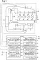
- a device for determining abnormality in an engine system will now be described with reference to Figs. 1 to 6 .
- the engine system includes a diesel engine 10 (hereinafter, referred to simply as the engine 10).
- the engine 10 has a cylinder block 11 including first to fourth cylinders #1, #2, #3, and #4.
- Each cylinder has a fuel injection valve 13, from which fuel is injected into the cylinder.
- An intake manifold 14 for supplying operation gas to each cylinder and an exhaust manifold 15, into which exhaust gas from each cylinder flows, are coupled to the cylinder block 11.
- An intake passage 16 is coupled to the intake manifold 14, and intake air is introduced to the intake passage 16 through an air cleaner (not shown).
- the intake air is cooled by an intercooler 19 after being pressurized by the compressor 18 of a turbo charger 17.
- An exhaust passage 20 is coupled to the exhaust manifold 15, and a turbine 22, which constitutes the turbo charger 17, is arranged on the exhaust passage 20.
- An EGR passage 25 is coupled to the exhaust manifold 15.
- the EGR passage 25 is coupled to the intake passage 16 and introduces some of the exhaust gas as EGR gas to the intake passage 16.
- An EGR cooler 26 for cooling EGR gas and an EGR valve 27, of which the open degree is controlled according to the operating state of the engine 10, are attached to the EGR passage 25.
- operation gas which is mixed gas of exhaust gas and intake air, is supplied to each cylinder.
- the engine system includes various types of sensors that detect information related to the operating state of the engine 10.
- An intake air amount sensor 31 which detects an intake air amount QA, is arranged upstream of the compressor 18.
- An oxygen concentration sensor 34 is arranged downstream of the turbine 22 and detects a residual oxygen concentration, which is the weight concentration of oxygen in the fluid flowing through the exhaust passage 20.
- the engine system includes a crank angle sensor 35 for detecting the crank angle of a crankshaft 28 and an accelerator sensor 36 for detecting an acceleration open degree ACC.
- the presence or absence of abnormality in the engine system is determined by an ECU 40, which is a device for determining abnormality.
- the ECU 40 determines the presence or absence of abnormality in the engine system based on detection signals from the aforementioned sensors.
- the abnormality includes misfires in the engine 10, abnormality in the injection characteristic of the fuel injection valve 13, and abnormality in the detection characteristic of the oxygen concentration sensor 34.
- the ECU 40 includes a microcomputer having a central processing unit (CPU), a non-volatile memory (ROM), and a volatile memory (RAM).
- the ECU 40 includes a control section 50 for executing various types of processes and a memory section 60 for storing various types of control programs and various types of data.
- the control section 50 includes a target injection amount calculation section 51, which figures out a cylinder into which fuel is injected and calculates a target injection amount QF, which is a target amount of fuel injected from the fuel injection valve 13 corresponding to the cylinder, e.g., based on a detection signal from the crank angle sensor 35 and the acceleration open degree ACC.
- a target injection amount calculation section 51 which figures out a cylinder into which fuel is injected and calculates a target injection amount QF, which is a target amount of fuel injected from the fuel injection valve 13 corresponding to the cylinder, e.g., based on a detection signal from the crank angle sensor 35 and the acceleration open degree ACC.
- the control section 50 includes an estimation section 52, which calculates the estimated value Ce of residual oxygen concentration.
- the estimation section 52 calculates the oxygen concentration (weight concentration) in air as the estimated value Ce when the target injection amount QF is less than or equal to zero.
- the estimation section 52 calculates the estimated value Ce based on the target injection amount QF and the intake air amount QA when the target injection amount QF is greater than zero.
- the estimation section 52 calculates the estimated value Ce by assigning the injection weight based on the target injection amount QF and the air weight based on the intake air amount QA to the following formula (1).
- the formula (1) is a model defined based on the results of various types of experiments conducted in the engine system. The introduced amount of EGR gas and the like may be considered in a model for estimating the estimated value Ce.
- estimated value Ce air weight injection weight ⁇ stoichiometric mixture ratio ⁇ injection weigth ⁇ oxygen concentration in air air weight
- the control section 50 includes a non-injection time determination section 53, which constitutes a first determination section.
- the non-injection time determination section 53 executes a non-injection time determination process that determines the high-low relationship between the detected value Cd and the estimated value Ce in the non-fuel-injecting state and stores the determination result in the first determination result storage section 61 of the memory section 60.
- the non-injection time determination section 53 starts the non-injection time determination process when the engine 10 is started and normality is determined in the abnormality determination process, which will be described later.
- the non-injection time determination section 53 initializes the first determination result storage section 61 when the non-injection time determination process is started.
- the non-injection time determination section 53 determines that the engine 10 is in a non-injection stable state when a state in which the target injection amount QF is less than or equal to zero continues for a predetermined period. In the non-injection stable state subsequent to the determination, the non-injection time determination section 53 obtains the oxygen concentration (weight concentration) in air as the estimated value Ce and obtains the detected value Cd based on the detection signal of the oxygen concentration sensor 34.
- the non-injection time determination section 53 determines the high-low relationship between the detected value Cd and the estimated value Ce based on the divergence degree of the detected value Cd relative to the estimated value Ce. In the non-injection time determination process, the non-injection time determination section 53 obtains "High,” with which it is determined that the detected value Cd is higher than the estimated value Ce, "Low,” with which it is determined that the detected value Cd is lower than the estimated value Ce, or "Normal,” with which it is determined that the detected value Cd is equal to the estimated value Ce, as a first determination result.
- the divergence degree when it is determined that the detected value Cd is higher than the estimated value Ce, the divergence degree when it is determined that the detected value Cd is equal to the estimated value Ce, and the divergence degree when it is determined that the detected value Cd is lower than the estimated value Ce are individually set based on the results of the various types of experiments conducted for the engine system.
- the control section 50 includes an injection time determination section 54, which constitutes the first determination section.
- the injection time determination section 54 executes an injection time determination process, which determines the high-low relationship between the detected value Cd and the estimated value Ce in a fuel-injecting state and stores the determination result in the second determination result storage section 63 of the memory section 60.
- the injection time determination section 54 starts the injection time determination process when the engine 10 is started and normality is determined in the abnormality determination process, which will be described later.
- the injection time determination section 54 initializes an injection data storage section 62 and a second determination result storage section 63 when the injection time determination process is started.
- the injection time determination section 54 determines that the engine 10 is in an injection stable state when a state in which the derivative value of a target injection amount QF, which is the deviation between two sequential target injection amounts QF, is less than or equal to a predetermined value continues for a predetermined period.
- the injection time determination section 54 calculates estimated values Ce, obtains detected values Cd, and stores these estimated values Ce and detected values Cd in the injection data storage section 62 of the memory section 60.
- the injection time determination section 54 calculates an average estimated value ECe, which is the average of the estimated values Ce stored in the injection data storage section 62, and an average detected value ECd, which is the average of the detected values Cd stored in the injection data storage section 62.
- the injection time determination section 54 compares the average detected value ECd with the average estimated value ECe and determines the high-low relationship between the average detected value ECd and the average estimated value ECe based on the divergence degree of the average detected value ECd relative to the average estimated value ECe.
- the injection time determination section 54 obtains "High,” with which it is determined that the average detected value ECd is higher than the average estimated value ECe, "Low,” with which it is determined that the average detected value ECd is lower than the average estimated value ECe, or "normal,” with which it is determined that the average detected value ECd is equal to the average estimated value ECe as a second determination result.
- the divergence degree when it is determined that the average detected value ECd is higher than the average estimated value ECe, the divergence degree when it is determined that the average detected value ECd is equal to the average estimated value ECe, and the divergence degree when it is determined that the average detected value ECd is lower than the average estimated value ECe are individually set based on the results of the various types of experiments conducted for the engine system.
- the control section 50 includes an angular acceleration determination section 55, which is a second determination section.
- the angular acceleration determination section 55 obtains individual cylinder angular accelerations a1, a2, a3, and a4, each of which is the angular acceleration of the crankshaft 28 in an expansion stroke of the corresponding cylinder based on the detection signal of the crank angle sensor 35.
- the angular acceleration determination section 55 executes an angular acceleration determination process, which determines the high-low relationship between each of the individual cylinder angular accelerations a1 to a4 and an all-cylinder angular acceleration Ea, which is the average of the individual cylinder angular accelerations a1 to a4, and stores the determination result in the third determination result storage section 65 of the memory section 60.
- the angular acceleration determination section 55 starts the angular acceleration determination process when the engine 10 is started and normality is determined in the abnormality determination process, which will be described later.
- the angular acceleration determination section 55 initializes an angular acceleration storage section 64 and a third determination result storage section 65 when the angular acceleration determination process is started.
- the angular acceleration determination section 55 determines whether the engine 10 is in a steady state.
- the angular acceleration determination section 55 determines that the engine 10 is in the steady state when both of the following conditions are continuously satisfied for a predetermined period.
- One of the conditions is that the derivative value of an engine rotation speed Ne based on the detection signal of the crank angle sensor 35 is less than or equal to a predetermined value.
- the other is that the derivative value of the target injection amount QF is less than or equal to a predetermined value.
- the angular acceleration determination section 55 repeatedly calculates the angular acceleration of the crankshaft 28 in the expansion stroke of each cylinder based on the detection signal of the crank angle sensor 35 and stores the calculated angular acceleration in the angular acceleration storage section 64 of the memory section 60.
- the angular acceleration storage section 64 has an area that stores the angular acceleration for each cylinder.
- the angular acceleration determination section 55 calculates the individual cylinder angular acceleration a1 (a2, a3, a4) for each cylinder based on the angular accelerations of the cylinder, which are stored in the angular acceleration storage section 64.
- each of the angular accelerations a1 to a4 is the average of the angular accelerations for the corresponding cylinder, which are repeatedly calculated and stored during the predetermined period.
- the angular acceleration determination section 55 calculates the average of the individual cylinder angular accelerations a1 to a4 as an all-cylinder angular acceleration Ea.
- the angular acceleration determination section 55 compares each of the individual cylinder angular accelerations a1 to a4 with the all-cylinder angular acceleration Ea, determines, for each cylinder, the high-low relationship between the individual cylinder angular acceleration and the all-cylinder angular acceleration Ea based on the divergence degree of the individual cylinder angular acceleration a1 (a2, a3, a4) relative to the all-cylinder angular acceleration Ea, and stores the determination result in a third determination result storage section 65 of the memory section 60.
- the angular acceleration determination section 55 obtains, for each cylinder, "High,” with which it is determined that the individual cylinder angular acceleration is higher than the all-cylinder angular acceleration Ea , "Low,” with which it is determined that the individual cylinder angular acceleration is lower than the all-cylinder angular acceleration Ea, or "Normal,” with which it is determined that the individual cylinder angular acceleration is equal to the all-cylinder angular acceleration Ea, as a third determination result.
- the divergence degree when it is determined that the individual cylinder angular acceleration is higher than the all-cylinder angular acceleration, the divergence degree when it is determined that the individual cylinder angular acceleration is equal to the all-cylinder angular acceleration, and the divergence degree when it is determined that the individual cylinder angular acceleration is lower than the all-cylinder angular acceleration are individually set based on the results of the various types of experiments conducted for the engine system.
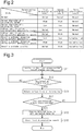
- the control section 50 includes an abnormality determination section 56, which executes the abnormality determination process, which determines the presence or absence of abnormality and identifies its abnormality location in the engine system based on the determination results stored in the determination result storage sections 61, 63, and 65 and a reference table 66 pre-stored in the memory section 60.
- the abnormality determination process starts from the start of the engine 10 and finishes at the abnormality determination of the engine system.
- the reference table 66 is data in which the first to third determination results are associated with the state of the engine system. When all of the first to third determination results are "Normal,” the abnormality determination section 56 determines that the engine system is normal. When at least one of the first to third determination results is abnormal, the abnormality determination section 56 determines that the engine system is abnormal.
- the abnormality determination section 56 When concluding the abnormality determination for the engine system, the abnormality determination section 56 turns on an alarm lamp 67 to notify the driver of the occurrence of abnormality in the engine system and memorizes the state of the abnormality in a predetermined area of the memory section 60.
- the ECU 40 first initializes the first determination result storage section 61 (step S11). Next, the ECU 40 determines whether the current state is a non-injection stable state (step S12). When the non-injection stable state is denied (step S12: NO), the ECU 40 repeatedly determines whether the current state is the non-injection stable state.
- step S12 When the non-injection stable state is confirmed (step S12: YES), the ECU 40 obtains various types of information including the detected value Cd and the calculated target injection amount QF (step S13). The ECU 40 determines whether the non-injection stable state still continues based on the information (step S14). When the non-injection stable state does not continue (step S14: NO), the ECU 40 shifts to the process at step S12 again. When the non-injection stable state continues (step S14: YES), the ECU 40 compares the detected value Cd with the oxygen concentration in air as the estimated value Ce (step S15). The ECU 40 stores the comparison result at step S15 as the first determination result in the first determination result storage section 61 (step S16) and finishes the non-injection time determination process.
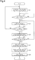
- the ECU 40 first initializes the injection data storage section 62 and the second determination result storage section 63 (step S21). Next, the ECU 40 determines whether the current state is the injection stable state (step S22). When the injection stable state is denied (step S22: NO), the ECU 40 repeatedly determines whether the current state is the injection stable state.
- step S22 When the injection stable state is confirmed (step S22: YES), the ECU 40 obtains various types of information including the intake air amount QA, the detected value Cd, and the calculated target injection amount QF (step S23). The ECU 40 determines whether the injection stable state continues based on the information (step S24). When the injection stable state is denied (step S24: NO), the ECU 40 shifts to the process at step S21 again.
- the ECU 40 calculates the estimated value Ce by assigning the injection weight based on the target injection amount QF and the air weight based on the intake air amount QA to the formula (1), and stores the calculated estimated value Ce and the detected value Cd obtained at step S23 in the injection data storage section 62 (step S25).
- the ECU 40 determines whether a predetermined period has passed in the injection stable state after the injection stable state is determined at step S22 (step S26).
- the predetermined period has not passed in the injection stable state (step S26: NO)
- the ECU 40 shifts to the process at step S23 again.
- the predetermined period has passed in the injection stable state (step S26:YES)
- the ECU 40 calculates the average estimated value ECe and the average detected value ECd based on the estimated values Ce and the detected values Cd, which are stored in the injection data storage section 62 (step S27).
- the ECU 40 compares the average detected value ECd with the average estimated value ECe (step S28), stores the comparison result as the second determination result in the second determination result storage section 63 (step S29), and finishes the injection time determination process.
- the ECU 40 first initializes the angular acceleration storage section 64 and the third determination result storage section 65 (step S31). Next, the ECU 40 determines whether the engine 10 is in the steady state (step S32). When the engine 10 is not in the steady state (step S32: NO), the ECU 40 repeatedly determines whether the engine 10 is in the steady state.
- step S32 When the engine 10 is in the steady state (step S32: YES), the ECU 40 obtains various types of information including the engine rotation speed Ne, a cylinder which fuel is injected into, and the calculated target injection amount QF (step S33). The ECU 40 determines whether the steady state continues based on the information (step S34). When the steady state does not continue (step S34: NO), the ECU 40 shifts to the process at step S31 again. When the steady state continues (step S34: YES), the ECU 40 calculates the angular acceleration of the cylinder into which fuel is injected based on the detection signal of the crank angle sensor 35 and stores the calculated angular acceleration in the angular acceleration storage section 64 (step S35).
- the ECU 40 determines whether a predetermined period has passed after it was determined that the engine 10 was in the steady state at step S32. When the predetermined period has not passed (step S36: NO), the ECU 40 shifts to the process at step S33 again. When the predetermined period has passed (step S36: YES), the ECU 40 calculates the individual cylinder angular accelerations a1 to a4 and the all-cylinder angular acceleration Ea based on the angular accelerations stored in the angular acceleration storage section 64 (step S37).
- the ECU 40 compares each individual cylinder angular acceleration a1 (a2, a3, a4) with the all-cylinder angular acceleration Ea (step S38), stores the comparison result as the third determination result in the third determination result storage section 65 (step S39), and finishes the angular acceleration determination process.
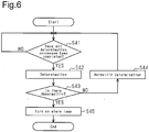
- the ECU 40 first determines whether all the non-injection time determination process, the injection time determination process, and the angular acceleration determination process have been completed (step S41). When all of the determination processes have not been completed (step S41: NO), the ECU 40 repeatedly determines whether all of the determination processes have been completed.
- step S41 determines the presence or absence of abnormality and identifies its abnormality location in the engine system based on the determination results of the determination processes stored in the memory section 60 and the reference table 66 (step S42).
- step S43: NO the ECU 40 determines normality (step S44) and after that, shifts to the process at step S41 again.
- step S45 the ECU 40 turns on the alarm lamp 67 (step S45) and finishes the abnormality determination process.
- the ECU 40 determines abnormality of the oxygen concentration sensor 34, abnormality of the fuel injection valve 13, and misfires in the engine 10 based on various types of information that is obtained when the engine 10 is in the non-injection stable state, the injection stable state, or the steady state.
- the non-injection stable state is an operating state embodied in a state in which the accelerator pedal is not depressed during traveling of the vehicle.
- the fuel-injecting state is an operating state embodied in a state in which the accelerator pedal is depressed during traveling of the vehicle.
- the non-injection stable state, the injection stable state, the steady state are operating states embodied during traveling of the vehicle. As a result, even during traveling of the vehicle, it is possible to determine the presence or absence of abnormality in the engine system.
- the device for determining abnormality achieves the following advantages.
- the embodiment may be modified as long as the individual cylinder angular accelerations a1 to a4 are angular accelerations in the steady state.
- Each of the individual cylinder angular accelerations a1 to a4 does not necessarily need to be the average of angular accelerations during a predetermined period.
- the embodiment may be modified as long as the individual cylinder angular accelerations a1 to a4 are angular accelerations of the crankshaft 28 in the fuel-injecting state.
- the individual cylinder angular accelerations a1 to a4 may be angular accelerations when the operating state of the engine 10 is an accelerating state.
- the all-cylinder angular acceleration Ea does not necessarily need to be the average of the individual cylinder angular accelerations a1 to a4 and may be the average of all angular accelerations used in calculating the individual cylinder angular accelerations a1 to a4.
- the embodiment may be modified as long as determination is conducted based on an estimated value Ce and a detected value Cd in the fuel-injecting state, and determination is not limited to comparison between averages. For example, the determination may be conducted based on one estimated value Ce and one detected value.
- the embodiment may be modified as long as determination is conducted based on the estimated value Ce and the detected value Cd in the fuel-injecting state.
- the determination may be conducted based on the estimated value Ce and the detected value Cd in a state that the engine 10 is not in the injection stable state.
- the embodiment may be modified as long as determination is conducted based on the detected value Cd in the non-fuel-injecting state. For example, determination may be conducted based on the detected value Cd immediately after the state of the engine 10 has shifted to the non-fuel-injecting state or may be conducted based on the average of detected values Cd.
- the engine is not limited to the diesel engine 10.
- the engine may be a gasoline engine.
Landscapes
- Engineering & Computer Science (AREA)
- Chemical & Material Sciences (AREA)
- Combustion & Propulsion (AREA)
- Mechanical Engineering (AREA)
- General Engineering & Computer Science (AREA)
- Physics & Mathematics (AREA)
- General Physics & Mathematics (AREA)
- Health & Medical Sciences (AREA)
- Emergency Medicine (AREA)
- Combined Controls Of Internal Combustion Engines (AREA)
- Electrical Control Of Air Or Fuel Supplied To Internal-Combustion Engine (AREA)
Applications Claiming Priority (2)
| Application Number | Priority Date | Filing Date | Title |
|---|---|---|---|
| JP2014046276A JP6286236B2 (ja) | 2014-03-10 | 2014-03-10 | エンジンシステムの異常判定装置 |
| PCT/JP2015/054094 WO2015137047A1 (fr) | 2014-03-10 | 2015-02-16 | Dispositif pour déterminer une anomalie dans un système de moteur |
Publications (2)
| Publication Number | Publication Date |
|---|---|
| EP3118441A1 true EP3118441A1 (fr) | 2017-01-18 |
| EP3118441A4 EP3118441A4 (fr) | 2017-10-18 |
Family
ID=54071498
Family Applications (1)
| Application Number | Title | Priority Date | Filing Date |
|---|---|---|---|
| EP15761925.5A Withdrawn EP3118441A4 (fr) | 2014-03-10 | 2015-02-16 | Dispositif pour déterminer une anomalie dans un système de moteur |
Country Status (5)
| Country | Link |
|---|---|
| US (1) | US10054074B2 (fr) |
| EP (1) | EP3118441A4 (fr) |
| JP (1) | JP6286236B2 (fr) |
| CN (1) | CN106103955B (fr) |
| WO (1) | WO2015137047A1 (fr) |
Families Citing this family (5)
| Publication number | Priority date | Publication date | Assignee | Title |
|---|---|---|---|---|
| US11482126B2 (en) | 2017-10-03 | 2022-10-25 | ExtendView, Inc. | Augmented reality system for providing movement sequences and monitoring performance |
| JP6853287B2 (ja) * | 2019-02-21 | 2021-03-31 | トヨタ自動車株式会社 | インバランス検出装置、インバランス検出システム、データ解析装置、および内燃機関の制御装置 |
| EP3696395A1 (fr) | 2019-02-15 | 2020-08-19 | Toyota Jidosha Kabushiki Kaisha | Système de détection d'état pour moteur à combustion interne, dispositif d'analyse de données et véhicule |
| US11255282B2 (en) | 2019-02-15 | 2022-02-22 | Toyota Jidosha Kabushiki Kaisha | State detection system for internal combustion engine, data analysis device, and vehicle |
| US11454180B1 (en) * | 2021-06-17 | 2022-09-27 | Cummins Inc. | Systems and methods for exhaust gas recirculation |
Family Cites Families (20)
| Publication number | Priority date | Publication date | Assignee | Title |
|---|---|---|---|---|
| JP2503742B2 (ja) * | 1990-08-04 | 1996-06-05 | 三菱電機株式会社 | 内燃機関燃料制御システム |
| JP2807769B2 (ja) * | 1990-08-30 | 1998-10-08 | 本田技研工業株式会社 | 内燃エンジンの制御装置の故障診断方法 |
| JPH04265475A (ja) * | 1991-02-20 | 1992-09-21 | Fuji Heavy Ind Ltd | エンジンの気筒別失火判別方法 |
| EP0610508B1 (fr) * | 1992-06-09 | 1996-10-16 | Mitsubishi Jidosha Kogyo Kabushiki Kaisha | Methode de detection des rates d'allumage en utilisant les fluctuations de rotation du vilebrequin |
| EP0744609B1 (fr) * | 1992-06-09 | 2001-11-14 | Mitsubishi Jidosha Kogyo Kabushiki Kaisha | Méthode de détection de Ratés d'allumage |
| AU665259B2 (en) * | 1992-06-16 | 1995-12-21 | Mitsubishi Jidosha Kogyo Kabushiki Kaisha | Misfire detecting method |
| DE4243493A1 (de) * | 1992-12-22 | 1994-06-23 | Bosch Gmbh Robert | Verfahren und Vorrichtung zur Überwachung einer Steuereinrichtung |
| JP2856014B2 (ja) * | 1993-02-05 | 1999-02-10 | 三菱自動車工業株式会社 | クランク軸回転変動による失火検出方法 |
| JP3972432B2 (ja) * | 1996-11-27 | 2007-09-05 | 株式会社デンソー | 内燃機関制御用の酸素濃度センサの学習装置及びその学習方法 |
| JP2003193903A (ja) * | 2001-12-25 | 2003-07-09 | Mitsubishi Motors Corp | 空燃比検出手段の故障判定装置 |
| JP2003314352A (ja) * | 2002-04-17 | 2003-11-06 | Mitsubishi Electric Corp | 内燃機関の失火検出装置 |
| JP2007327406A (ja) * | 2006-06-07 | 2007-12-20 | Toyota Motor Corp | 内燃機関の制御装置及び方法 |
| JP4929966B2 (ja) * | 2006-09-15 | 2012-05-09 | 株式会社デンソー | 燃料噴射制御装置 |
| JP2010112211A (ja) | 2008-11-05 | 2010-05-20 | Hino Motors Ltd | 内燃機関の異常判定装置 |
| JP2011027059A (ja) * | 2009-07-28 | 2011-02-10 | Hitachi Automotive Systems Ltd | エンジンの制御装置 |
| JP2011085020A (ja) * | 2009-10-13 | 2011-04-28 | Denso Corp | 酸素濃度センサの大気学習装置 |
| JP2011163229A (ja) * | 2010-02-10 | 2011-08-25 | Toyota Motor Corp | 多気筒内燃機関の気筒間空燃比インバランス判定装置 |
| EP2657495A4 (fr) * | 2010-12-24 | 2014-07-30 | Toyota Motor Co Ltd | Dispositif et procédé de détection d'erreur de variation de rapport air-carburant inter-cylindre |
| JP5265724B2 (ja) * | 2011-03-29 | 2013-08-14 | 本田技研工業株式会社 | エンジンの故障診断方法、故障診断システム及び故障診断機 |
| US9146177B2 (en) * | 2012-08-03 | 2015-09-29 | GM Global Technology Operations LLC | System and method for diagnosing a fault in an oxygen sensor based on engine speed |
-
2014
- 2014-03-10 JP JP2014046276A patent/JP6286236B2/ja not_active Expired - Fee Related
-
2015
- 2015-02-16 CN CN201580012613.XA patent/CN106103955B/zh not_active Expired - Fee Related
- 2015-02-16 EP EP15761925.5A patent/EP3118441A4/fr not_active Withdrawn
- 2015-02-16 WO PCT/JP2015/054094 patent/WO2015137047A1/fr active Application Filing
- 2015-02-16 US US15/122,523 patent/US10054074B2/en not_active Expired - Fee Related
Also Published As
| Publication number | Publication date |
|---|---|
| CN106103955B (zh) | 2019-08-23 |
| US20170067405A1 (en) | 2017-03-09 |
| CN106103955A (zh) | 2016-11-09 |
| WO2015137047A1 (fr) | 2015-09-17 |
| JP2015169169A (ja) | 2015-09-28 |
| EP3118441A4 (fr) | 2017-10-18 |
| US10054074B2 (en) | 2018-08-21 |
| JP6286236B2 (ja) | 2018-02-28 |
Similar Documents
| Publication | Publication Date | Title |
|---|---|---|
| EP3179087B1 (fr) | Unité de détermination d'erreur | |
| US8548718B2 (en) | Air/fuel ratio variation abnormality detection apparatus, and abnormality detection method | |
| US9829414B2 (en) | Fault detection device and fault detection method | |
| US8805609B2 (en) | Apparatus and method for detecting abnormal air-fuel ratio variation | |
| US8234916B2 (en) | Abnormality diagnosis device for air-fuel ratio sensor | |
| EP3118441A1 (fr) | Dispositif pour déterminer une anomalie dans un système de moteur | |
| US7849844B2 (en) | Diagnostic method and device for operating an internal combustion engine | |
| US7681565B2 (en) | Air/fuel ratio control system for internal combustion engine | |
| EP2530262A1 (fr) | UNITÉ DE COMMANDE DE MOTEUR À COMBUSTION INTERNE ET DISPOSITIF POUR MESURER LE DÉBIT MASSIQUE DES NOx RENVOYÉS AU PASSAGE D'ADMISSION AVEC LE GAZ DE FUITE | |
| US9869262B2 (en) | System and process for predicting and preventing pre-ignition | |
| US10443475B2 (en) | Secondary air system in an exhaust gas purification system of an internal combustion engine | |
| US20120185157A1 (en) | Apparatus for detecting air-fuel ratio dispersion abnormality between cylinders of multiple-cylinder internal combustion engine | |
| JP2007085176A (ja) | 気筒別燃料噴射弁故障診断 | |
| US20120109497A1 (en) | Abnormal inter-cylinder air-fuel ratio imbalance detection apparatus for multi-cylinder internal combustion engine | |
| US10495015B2 (en) | Diagnostic device | |
| US7200508B2 (en) | Method and device for monitoring a control unit of an internal combustion engine | |
| JP2010163932A (ja) | 内燃機関の触媒劣化診断装置 | |
| US9328685B2 (en) | Inter-cylinder air-fuel ratio variation abnormality detection apparatus for multicylinder internal combustion engine | |
| US20150114376A1 (en) | Inter-cylinder air-fuel ratio variation abnormality detection apparatus | |
| US9217384B2 (en) | Diagnosis method and device for operating an internal combustion engine | |
| US20160186637A1 (en) | Failure determination apparatus for oxygen concentration sensor | |
| JP2009091920A (ja) | 燃料供給異常判定方法およびその装置 | |
| JP2008175180A (ja) | 燃料供給異常判定方法およびその装置 | |
| JP6367045B2 (ja) | 燃料噴射制御装置及び燃料噴射制御方法 | |
| JP2009085078A (ja) | 燃料供給異常判定方法およびその装置 |
Legal Events
| Date | Code | Title | Description |
|---|---|---|---|
| PUAI | Public reference made under article 153(3) epc to a published international application that has entered the european phase |
Free format text: ORIGINAL CODE: 0009012 |
|
| 17P | Request for examination filed |
Effective date: 20160831 |
|
| AK | Designated contracting states |
Kind code of ref document: A1 Designated state(s): AL AT BE BG CH CY CZ DE DK EE ES FI FR GB GR HR HU IE IS IT LI LT LU LV MC MK MT NL NO PL PT RO RS SE SI SK SM TR |
|
| AX | Request for extension of the european patent |
Extension state: BA ME |
|
| DAX | Request for extension of the european patent (deleted) | ||
| A4 | Supplementary search report drawn up and despatched |
Effective date: 20170920 |
|
| RIC1 | Information provided on ipc code assigned before grant |
Ipc: F02D 41/14 20060101ALI20170913BHEP Ipc: F02D 41/12 20060101ALI20170913BHEP Ipc: F02D 45/00 20060101AFI20170913BHEP |
|
| GRAP | Despatch of communication of intention to grant a patent |
Free format text: ORIGINAL CODE: EPIDOSNIGR1 |
|
| RIC1 | Information provided on ipc code assigned before grant |
Ipc: F02D 45/00 20060101AFI20191001BHEP Ipc: F02D 41/14 20060101ALI20191001BHEP Ipc: F02D 41/12 20060101ALI20191001BHEP |
|
| INTG | Intention to grant announced |
Effective date: 20191018 |
|
| STAA | Information on the status of an ep patent application or granted ep patent |
Free format text: STATUS: THE APPLICATION IS DEEMED TO BE WITHDRAWN |
|
| 18D | Application deemed to be withdrawn |
Effective date: 20200229 |