EP3117941B1 - Insert de coupe et outil de coupe - Google Patents
Insert de coupe et outil de coupe Download PDFInfo
- Publication number
- EP3117941B1 EP3117941B1 EP15863062.4A EP15863062A EP3117941B1 EP 3117941 B1 EP3117941 B1 EP 3117941B1 EP 15863062 A EP15863062 A EP 15863062A EP 3117941 B1 EP3117941 B1 EP 3117941B1
- Authority
- EP
- European Patent Office
- Prior art keywords
- cutting
- cutting edge
- insert
- arc
- cutting insert
- Prior art date
- Legal status (The legal status is an assumption and is not a legal conclusion. Google has not performed a legal analysis and makes no representation as to the accuracy of the status listed.)
- Active
Links
- 238000005520 cutting process Methods 0.000 title claims description 475
- 230000002093 peripheral effect Effects 0.000 claims description 33
- 230000001154 acute effect Effects 0.000 claims description 6
- 238000013459 approach Methods 0.000 description 10
- 239000000463 material Substances 0.000 description 7
- 238000003754 machining Methods 0.000 description 6
- 230000000694 effects Effects 0.000 description 5
- 238000004519 manufacturing process Methods 0.000 description 4
- 238000000034 method Methods 0.000 description 3
- 230000009471 action Effects 0.000 description 2
- 229910003460 diamond Inorganic materials 0.000 description 2
- 239000010432 diamond Substances 0.000 description 2
- 238000007599 discharging Methods 0.000 description 2
- 238000000227 grinding Methods 0.000 description 2
- 230000006872 improvement Effects 0.000 description 2
- 238000012986 modification Methods 0.000 description 2
- 230000004048 modification Effects 0.000 description 2
- 230000008569 process Effects 0.000 description 2
- 229910052582 BN Inorganic materials 0.000 description 1
- PZNSFCLAULLKQX-UHFFFAOYSA-N Boron nitride Chemical compound N#B PZNSFCLAULLKQX-UHFFFAOYSA-N 0.000 description 1
- 229910000831 Steel Inorganic materials 0.000 description 1
- 230000004075 alteration Effects 0.000 description 1
- 229910052796 boron Inorganic materials 0.000 description 1
- 229910052799 carbon Inorganic materials 0.000 description 1
- 239000000919 ceramic Substances 0.000 description 1
- 239000011195 cermet Substances 0.000 description 1
- 239000011248 coating agent Substances 0.000 description 1
- 238000000576 coating method Methods 0.000 description 1
- 238000007796 conventional method Methods 0.000 description 1
- 230000001419 dependent effect Effects 0.000 description 1
- 230000000994 depressogenic effect Effects 0.000 description 1
- 238000005553 drilling Methods 0.000 description 1
- 230000002349 favourable effect Effects 0.000 description 1
- 239000000843 powder Substances 0.000 description 1
- 238000003825 pressing Methods 0.000 description 1
- 230000001105 regulatory effect Effects 0.000 description 1
- 238000005245 sintering Methods 0.000 description 1
- 239000010959 steel Substances 0.000 description 1
Images


Classifications
-
- B—PERFORMING OPERATIONS; TRANSPORTING
- B23—MACHINE TOOLS; METAL-WORKING NOT OTHERWISE PROVIDED FOR
- B23C—MILLING
- B23C5/00—Milling-cutters
- B23C5/16—Milling-cutters characterised by physical features other than shape
- B23C5/20—Milling-cutters characterised by physical features other than shape with removable cutter bits or teeth or cutting inserts
- B23C5/202—Plate-like cutting inserts with special form
-
- B—PERFORMING OPERATIONS; TRANSPORTING
- B23—MACHINE TOOLS; METAL-WORKING NOT OTHERWISE PROVIDED FOR
- B23C—MILLING
- B23C5/00—Milling-cutters
- B23C5/02—Milling-cutters characterised by the shape of the cutter
- B23C5/10—Shank-type cutters, i.e. with an integral shaft
-
- B—PERFORMING OPERATIONS; TRANSPORTING
- B23—MACHINE TOOLS; METAL-WORKING NOT OTHERWISE PROVIDED FOR
- B23C—MILLING
- B23C5/00—Milling-cutters
- B23C5/02—Milling-cutters characterised by the shape of the cutter
- B23C5/10—Shank-type cutters, i.e. with an integral shaft
- B23C5/1009—Ball nose end mills
- B23C5/1027—Ball nose end mills with one or more removable cutting inserts
-
- B—PERFORMING OPERATIONS; TRANSPORTING
- B23—MACHINE TOOLS; METAL-WORKING NOT OTHERWISE PROVIDED FOR
- B23C—MILLING
- B23C5/00—Milling-cutters
- B23C5/02—Milling-cutters characterised by the shape of the cutter
- B23C5/10—Shank-type cutters, i.e. with an integral shaft
- B23C5/109—Shank-type cutters, i.e. with an integral shaft with removable cutting inserts
-
- B—PERFORMING OPERATIONS; TRANSPORTING
- B23—MACHINE TOOLS; METAL-WORKING NOT OTHERWISE PROVIDED FOR
- B23C—MILLING
- B23C5/00—Milling-cutters
- B23C5/16—Milling-cutters characterised by physical features other than shape
- B23C5/20—Milling-cutters characterised by physical features other than shape with removable cutter bits or teeth or cutting inserts
- B23C5/22—Securing arrangements for bits or teeth or cutting inserts
- B23C5/2204—Securing arrangements for bits or teeth or cutting inserts with cutting inserts clamped against the walls of the recess in the cutter body by a clamping member acting upon the wall of a hole in the insert
- B23C5/2208—Securing arrangements for bits or teeth or cutting inserts with cutting inserts clamped against the walls of the recess in the cutter body by a clamping member acting upon the wall of a hole in the insert for plate-like cutting inserts
- B23C5/2213—Securing arrangements for bits or teeth or cutting inserts with cutting inserts clamped against the walls of the recess in the cutter body by a clamping member acting upon the wall of a hole in the insert for plate-like cutting inserts having a special shape
-
- B—PERFORMING OPERATIONS; TRANSPORTING
- B23—MACHINE TOOLS; METAL-WORKING NOT OTHERWISE PROVIDED FOR
- B23C—MILLING
- B23C2200/00—Details of milling cutting inserts
- B23C2200/04—Overall shape
- B23C2200/045—Round
-
- B—PERFORMING OPERATIONS; TRANSPORTING
- B23—MACHINE TOOLS; METAL-WORKING NOT OTHERWISE PROVIDED FOR
- B23C—MILLING
- B23C2200/00—Details of milling cutting inserts
- B23C2200/08—Rake or top surfaces
- B23C2200/085—Rake or top surfaces discontinuous
-
- B—PERFORMING OPERATIONS; TRANSPORTING
- B23—MACHINE TOOLS; METAL-WORKING NOT OTHERWISE PROVIDED FOR
- B23C—MILLING
- B23C2200/00—Details of milling cutting inserts
- B23C2200/16—Supporting or bottom surfaces
- B23C2200/164—Supporting or bottom surfaces discontinuous
-
- B—PERFORMING OPERATIONS; TRANSPORTING
- B23—MACHINE TOOLS; METAL-WORKING NOT OTHERWISE PROVIDED FOR
- B23C—MILLING
- B23C2200/00—Details of milling cutting inserts
- B23C2200/20—Top or side views of the cutting edge
- B23C2200/203—Curved cutting edges
-
- B—PERFORMING OPERATIONS; TRANSPORTING
- B23—MACHINE TOOLS; METAL-WORKING NOT OTHERWISE PROVIDED FOR
- B23C—MILLING
- B23C2210/00—Details of milling cutters
- B23C2210/16—Fixation of inserts or cutting bits in the tool
- B23C2210/168—Seats for cutting inserts, supports for replacable cutting bits
Definitions
- the present invention relates to a cutting insert which is removably mounted on a cutting tool and a cutting tool.
- a cutting tool which uses a cutting insert having a circular-arc-shaped cutting edge is widely used as it is suited for use in three-dimensional machining of shapes.
- a ball end mill and a radius end mill, etc. are known as this type of cutting tool.
- a cutting insert having a circular-arc-shaped cutting edge can be used suitably for copy machining, etc., not only for a rotary cutting tool but also for a cutting tool for lathes.
- the peripheral side surface of such cutting insert having a circular-arc-shaped cutting edge has a curved face which corresponds to the circular arc shape of the cutting edge.
- Patent Document 1 proposes a cutting insert and a cutting tool involving a measure for preventing rotation of the cutting insert in the rotating direction.
- the cutting insert 1 in Patent Document 1 comprises two circular end surfaces and a peripheral side surface and has circular-arc-shaped cutting edges which are formed in an intersecting edge between the peripheral side surface and the two end surfaces.
- Patent Document 2 describes another example of conventional cutting inserts and cutting tools.
- the cutting insert in Patent Document 2 comprises a first end surface, a second end surface and a peripheral side surface, and has a plurality of cutting edges formed in an intersecting edge between the first end surface and the peripheral side surface.
- the cutting insert is formed, for example, in a shape of 120-degree rotational symmetry, i.e., 3-fold rotational symmetry, with respect to the axis passing through the first and second end surfaces.
- the second end surface serves as a surface to be seated onto an insert seat.
- a plurality of contact surface portions is formed on the second end surface.
- the cutting edge has a portion which is inclined so as to be closer to the second end surface.
- the contact surface portion has a portion which is inclined in the same direction as the direction of the inclined portion of the cutting edge.
- Patent Document 3 discloses a cutting insert as per the preamble of claim 1.
- the cutting insert and cutting tool disclosed in Patent Document 1 having the flat portions provided as a contact surface in the peripheral side surface, bring about effects of suppressing shifting of the cutting insert during cutting.
- a thin part is generated around the cutting edge above and below the flat portion.
- the cutting insert and cutting tool in Patent Document 2 also bring about effects of suppressing shifting of the cutting insert during cutting.
- shifting of the cutting insert in the rotating direction it is necessary to provide a configuration for preventing rotation separately from the contact surface portion; therefore, there is still room for improvement. If the cutting insert is shifted during cutting, the cutting insert may be abnormally damaged, or the machining accuracy of the workpiece may be deteriorated.
- a cutting insert according to the present invention is defined in independent claim 1, the dependent claims being directed to preferred embodiments.
- the cutting insert according to the present invention is formed so that the contact surface portion in the second end surface, which is able to be in contact with the bottom surface of the insert seat of the tool body, is inclined relative to the direction of rotation of the cutting insert. Further, the holding surface portion in the bottom surface of the insert seat, which comes into contact with the contact surface portion, also has a corresponding inclination. Accordingly, when cutting resistance is applied during cutting, generation of a force in a direction to shift the cutting insert can be suppressed between the contact surface portion of the cutting insert and the holding surface portion of the insert seat, and, as a result, shifting of the cutting insert can be suppressed. In other words, the cutting insert can be prevented from being abnormally damaged, or the machining accuracy of the workpiece can be increased.
- Figs. 1 and 4 to 9 illustrate a cutting insert 1 according to the present embodiment.
- Fig. 9 is a sectional view cut along the line IX-IX in Fig. 4 .
- the center of the arc of a first circular-arc-shaped cutting edge 5a1 which will be described later, is defined as a center E
- a first reference plane B is defined as a plane including reference axis A and passing through the center E of the first circular-arc-shaped cutting edge 5a1
- the cut plane along the line IX-IX corresponds to the first reference plane B.
- a virtual plane orthogonal to the reference axis A is defined as a second reference plane C, as shown in Figs. 5 and 6 .
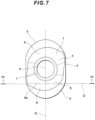
- Fig. 8 is a sectional view cut along the line VIII-VIII in Fig. 7 .
- the cut plane along the line VIII-VIII corresponds to the virtual plane D.
- the line VIII-VIII is a cutting-plane line in the shorter-side direction which is orthogonal to the longer-side direction in Fig. 4 .
- the back view and left side view of the cutting insert 1 are not shown herein since they are the same as the front view and the right side view, respectively.
- the cutting insert 1 of the present embodiment has a substantially elliptic shape in a plan view.
- substantially elliptic means a shape having two substantially semicircular parts in which the semicircular parts do not share their centers so that the two substantially semicircular parts are connected with two substantially linear parts.
- the substantially linear parts are smoothly tangential to each of the substantially semicircular parts.
- the longer-side direction of the ellipse is defined in a plan view as a direction extending from the reference axis A to the center of a virtual circle which has, as its arc, the curved line along the substantially semicircular part (hereinafter referred to as the "center of the semicircular arc").
- the longer-side direction of the ellipse is defined in a plan view as a direction extending from the center of one semicircular arc to the center of the other semicircular arc.
- the cutting insert 1 includes two end surfaces 2 and 3 which substantially face each other, i.e. which are arranged on substantially opposite sides from each other, and a peripheral side surface 4 extending between the two end surfaces.
- the cutting insert 1 is formed in a shape of 180-degree rotational symmetry, i.e., a shape of 2-fold rotational symmetry, with respect to the reference axis A that penetrates the two end surfaces 2 and 3.
- the respective centers E of the arcs in the two substantially semicircular parts are apart from the reference axis A by the same distance in the opposite directions.
- the curvature radius R of the arcs in the two substantially semicircular parts is the same.
- the reference axis A passes through the center of each of the first and second end surfaces 2 and 3.
- a mounting hole 7 is formed so as to extend through the two end surfaces 2 and 3 and arranged so that the axis of the mounting hole 7 corresponds to the reference axis A of the cutting insert 1.
- the reference axis A extends perpendicularly to the first end surface 2.
- the first end surface 2 and the second end surface 3 are arranged parallel to each other. Accordingly, the reference axis A extends perpendicularly to the second end surface 3 as well.
- the cutting insert 1 is formed so as to have the same shape when it is rotated 180 degrees around an axis orthogonal to the reference axis A so as to reverse the two end surfaces 2 and 3.
- one end surface 2 of the two end surfaces 2 and 3 is hereinafter referred to as an "upper surface” (corresponding to the "first end surface” of the present invention), and the other end surface 3 of the two end surfaces 2 and 3 is hereinafter referred to as a “lower surface” (corresponding to the "second end surface” of the present invention).
- the direction from the lower surface 3 to the upper surface 2 along the direction of the reference axis A is referred to as an "upward direction,” while the direction from the upper surface 2 to the lower surface 3 along the direction of the reference axis A is referred to as a “downward direction.”
- upward direction the direction from the upper surface 2 to the lower surface 3 along the direction of the reference axis A
- downward direction the direction from the upper surface 2 to the lower surface 3 along the direction of the reference axis A.
- a cutting edge 5 is formed in and along an intersecting edge between the upper surface 2 and the peripheral side surface 4.
- a rake surface is formed in the upper surface 2
- a flank is formed on the peripheral side surface 4
- a cutting edge 5 is formed in an intersecting edge between the rake surface and the flank.
- the cutting edge 5 is generally comprised of two portions 5a and 5b.
- the contour shape of the upper surface 2 includes substantially semicircular portions and substantially linear portions.
- the portion of the cutting edge 5 corresponding to the substantially semicircular portion is referred to as a circular-arc-shaped cutting edge 5a
- the remaining portion of the cutting edge 5 corresponding to the substantially linear portion is referred to as a linear cutting edge 5b.
- the linear cutting edge 5b may also be referred to as a second cutting edge 5b.
- the circular-arc-shaped cutting edge 5a is formed so that, in a plan view, the length along the circular-arc-shaped cutting edge 5a is longer than the length of the linear cutting edge 5b.
- the cutting edge 5 is configured such that it is mainly the circular-arc-shaped cutting edge 5a that functions.
- the curvature radius R of the arc of the circular-arc-shaped cutting edge 5a is about 4 mm in a plan view. Accordingly, the length along the circular-arc-shaped cutting edge 5a is about 12 mm. The length of the linear cutting edge 5b is about 5 mm in a plan view. It should be noted, however, that each length is not limited to the above. Each size of the cutting edge 5 can be adjusted as appropriate according to the shape of the workpiece, etc. Moreover, in the cutting insert 1 of the present embodiment, the cutting edge 5 is formed in the entire part of the intersecting edge between the upper surface 2 and the peripheral side surface 4; however, the configuration is not limited thereto. The cutting edge 5 may be formed in only a part of the intersecting edge.
- the cutting edge 5 is formed in only a part of the intersecting edge between the peripheral side surface 4 and the top and lower surfaces 2 and 3, it is preferable to form a curved connecting portion in the remaining part of the intersecting edge so as to smoothly connect each of the cutting edges 5.
- FIG. 4 a plan view of the cutting insert 1 ( Fig. 4 ).
- a virtual plane which passes through the above point E and includes the reference axis A can be defined as a first reference plane B, as described above.
- one of the circular-arc-shaped cutting edges 5a which corresponds to the substantially semicircular portions from which the above center point E has been determined, will be specifically referred to as a first circular-arc-shaped cutting edge 5a1.
- a virtual plane which extends perpendicularly to the reference axis A and is arranged on the upper surface 2 side with respect to the lower surface 3 can be defined as a second reference plane C.
- the second reference plane C is defined in the middle of the upper surface 2 and the lower surface 3, i.e., at a position that divides the cutting insert 1 into two substantially equal parts.
- the second reference plane C passes through the peripheral side surface 4, but does not intersect with either the upper surface 2 or the lower surface 3.
- a virtual plane which is orthogonal to both the first reference plane B and the second reference plane C and which extends so as to intersect with the first circular-arc-shaped cutting edge 5a1 and traverse a contact surface portion 6 (which will be described later) can be defined as a virtual plane D. That is, at least one contact surface portion 6 is formed on the reverse side of the corresponding rake surface of the first circular-arc-shaped cutting edge 5a1.
- the first circular-arc-shaped cutting edge 5a1 is formed so as to be generally inclined relative to the second reference plane C.
- the first circular-arc-shaped cutting edge 5a1 has an apex on the upper right side in Fig. 5 , the apex being a point at which the first circular-arc-shaped cutting edge 5a1 is the most distant from the second reference plane C.
- the first circular-arc-shaped cutting edge 5a1 has an inclined portion which gradually approaches the second reference plane C heading from the apex toward the first reference plane B.
- the first circular-arc-shaped cutting edge 5a1 also has an inclined portion which gradually approaches the second reference plane C heading from the apex toward the linear cutting edge 5b.
- the angle of inclination of the first circular-arc-shaped cutting edge 5a1 in Fig. 5 reaches a maximum value at a portion that crosses the first reference plane B, and, on both sides of that portion, the first circular-arc-shaped cutting edge 5a1 comes close to a state substantially parallel to the second reference plane C.
- the first circular-arc-shaped cutting edge 5a1 is curved in a substantially S-shape so as to project most outwardly (upward direction) at the apex.
- the first circular-arc-shaped cutting edge 5a1 is inclined so as to approach the second reference plane C heading from the apex toward the linear cutting edge 5b.
- the first circular-arc-shaped cutting edge 5a1 is formed so as to be inclined relative to the second reference plane C in Fig. 6 as well.
- the first circular-arc-shaped cutting edge 5a1 is inclined so as to approach the lower surface 3 heading from the apex toward the linear cutting edge 5b.
- the cutting insert 1 of the present embodiment is formed so that the linear cutting edge 5b is also inclined, in Fig. 6 , relative to the second reference plane C.
- the linear cutting edge 5b is inclined so as to approach the second reference plane C as it heads away from the first circular-arc-shaped cutting edge 5a1. Further, in Fig. 6 , one cutting edge 5 is inclined so that its circular-arc-shaped cutting edge 5a and linear cutting edge 5b are continuously inclined in the same direction, and so that it extends toward the adjacent cutting edge 5.
- the cutting insert 1 of the present embodiment has two sets, i.e., two cutting edges 5 formed on the upper surface 2 side. Accordingly, two circular-arc-shaped cutting edges 5a and two linear cutting edges 5b are formed.
- cutting edges 5 are also formed at an intersecting edge between the lower surface 3 and the peripheral side surface 4 in a similar manner to those on the upper surface 2 side. In other words, rake surfaces are also formed in the lower surface 3.
- Each of the cutting edges 5 is formed so that the same shape is generated when the cutting insert 1 is rotated 180 degrees about an axis orthogonal to the reference axis A such that the upper surface 2 and the lower surface 3 are reversed. Thus, four sets of cutting edges 5 are formed in total.
- the cutting insert 1 is economical since it can be used at least four times - twice by using the upper surface 2 side and twice by reversing the cutting insert and using the lower surface 3 side.
- the below description will be made only for the case where one cutting edge 5 on the upper surface 2 side is used. Since the other three cutting edges 5 are used in a similar manner, description thereof will be omitted here.
- the circular-arc-shaped cutting edge 5a of the working cutting edge which is used in the below description is assumed to be the above-described first circular-arc-shaped cutting edge 5a1.
- the first circular-arc-shaped cutting edge 5a1 which is one of the circular-arc-shaped cutting edges 5a, has been described regarding its shape, and since the remaining three circular-arc-shaped cutting edges 5a are the same as the first circular-arc-shaped cutting edge 5a1, the descriptions thereof will be omitted here.
- the shapes of the cutting edges of the cutting insert according to the present invention are not limited to the above-described shapes of the cutting insert 1. Whether or not the cutting edges 5 have inclination, as well as the angles of inclination, etc., may be adjusted as appropriate according to the workpiece material and the cutting conditions.
- the lower surface 3 of the cutting insert 1 has a plurality of contact surface portions 6 which are arranged so as to be rotationally symmetrical with respect to the reference axis A.
- the contact surface portion 6 is a surface for bringing the cutting insert 1 into contact with an insert seat 22 when the cutting insert 1 is mounted on a cutting tool 20. More specifically, the contact surface portion 6 is a surface to be seated onto the insert seat 22 of a tool body 21.
- four contact surface portions 6 are formed in total - two on the upper surface 2 and two on the lower surface 3.
- Each of the four contact surface portions 6 has a substantially flat surface. More specifically, each contact surface portion 6 in this example is a plane. As shown in Figs.
- the contact surface portions 6 are formed around the mounting hole 7 so that they surround the hole 7.
- the intersecting line between two virtual planes which are defined by extending the two contact surface portions 6 on the lower surface 3, respectively, intersects with the reference axis A and extends parallel to the second reference plane C.
- the contact surface portion 6 which is formed on the side of the first circular-arc-shaped cutting edge 5a1 is referred to as a first contact surface portion 6a. That is, the first contact surface portion 6a is formed on the reverse side (lower side) of the rake surface associated with the first circular-arc-shaped cutting edge 5a1.
- a virtual plane that is defined by extending the contact surface portion 6 intersects with the second reference plane C with an acute angle of inclination ⁇ . That is, the contact surface portion 6 forms an acute angle with the second reference plane C in a sectional view cut along the virtual plane D, i.e., a sectional view in the shorter-side direction.
- the contact surface portion 6 is inclined relative to the second reference plane C.
- the second reference plane C is parallel to the upper surface 2 and the lower surface 3.
- the contact surface portion 6 is part of the lower surface 3, but is an inclined portion in the lower surface 3.
- the circular-arc-shaped cutting edge 5a is formed so as to be inclined relative to the second reference plane C and the lower surface 3.
- the linear cutting edge 5b of the same cutting edge 5 is on the right side of Fig. 5 , although this is not shown in the drawing.
- the first circular-arc-shaped cutting edge 5a1 is generally curved so as to approach the second reference plane C as it heads away from the linear cutting edge 5b of the same cutting edge 5.
- the circular-arc-shaped cutting edge 5a is formed so as to be inclined relative to the second reference plane C and the lower surface 3.
- the cutting edge 5 including the first circular-arc-shaped cutting edge 5a1 on the upper surface 2 side, and the first contact surface portion 6a formed on the reverse side (lower side) of the rake surface related to such first circular-arc-shaped cutting edge 5a1.
- the first circular-arc-shaped cutting edge 5a1 is inclined, from the above-mentioned apex of this first circular-arc-shaped cutting edge 5a1, so as to approach the second reference plane C as it heads away from the linear cutting edge 5b of the same cutting edge 5. Meanwhile, when turning to Figs.
- the first contact surface portion 6a is inclined in the shorter-side direction of the cutting insert 1 so as to become more distant from the second reference plane C as it heads away from the side of the linear cutting edge 5b which is paired with the above first circular-arc-shaped cutting edge 5a1.
- the cutting edge 5 in a side view which is viewed from the direction that faces the virtual plane D, i.e., in a view from the front, the cutting edge 5 has an inclined portion which is inclined so as to make an acute angle with the second reference plane C.
- the direction of inclination of the first contact surface portion 6a is the same as the inclination direction of the inclined portion of the cutting edge 5. That is, the inclination direction of the inclined portion of the cutting edge 5, when it is projected onto the sectional view of Fig. 8 , also goes downward and to the left.
- the contact surface portion 6 is formed so as to be approximately at a right angle to the reference axis A, i.e., approximately parallel to the second reference plane C.
- portions near the cutting edges 5 are made of hard materials, such as a cemented carbide, cermet, ceramic, and a sintered body containing cubic boron nitride, materials obtained by applying PVD or CVD coating to the surface of these hard materials, or a sintered body containing mono-crystalline diamond or diamond. It should be noted that portions other than the portions near the cutting edges 5 are preferably made of similarly hard materials.
- the cutting insert 1 having the above-described configuration is removably mounted on the insert seat 22 in the tool body 21 of the cutting tool 20 of the present embodiment with a clamping member 30 which is a mechanical attaching means.
- the cutting tool 20 on which the cutting insert 1 is mounted will be further described below with reference to Figs. 2 , 3 and 9 .
- the cutting tool 20 of the present embodiment uses a fastening screw 30 as the clamping member 30.
- the cutting tool 20 has a tool body 21 provided with a plurality of insert seats 22 (two seats in this example).
- One cutting insert 1 can be removably mounted on each insert seat 22. It should be noted that, although it is not shown in the drawings, the present invention does not exclude a cutting tool having a tool body provided with only one insert seat.
- the tool body 21 is configured to rotate about a tool rotational axis G, which is defined so as to pass through the tool body 21 from the leading end 26 to the base end 27.
- the tool body 21 is generally formed in a substantially cylindrical shape.
- the two insert seats 22 are provided around the leading end 26 of the tool body 21 at equal distances.
- Each of a plurality of cutting inserts 21 used for this cutting tool 20 has the same configuration and the same shape.
- each of the plurality of insert seats 22 provided in the tool body 21 also has the same shape.
- the cutting tool 20 of the present embodiment is a rotary cutting tool. More specifically, the cutting tool 20 of the present embodiment is a radius end mill using the above-described cutting insert 1.
- the cutting insert 1 is mounted on each insert seat 22 in the tool body 21 so that the upper surface 2 or the lower surface 3 faces forward in the direction of tool rotation around the tool rotational axis.
- Each insert seat 22 has a bottom surface 23 and a wall surface 24, and is open toward the leading end 26 and the outer periphery of the tool body 21.
- a surface with which the upper surface 2 or the lower surface 3 of the cutting insert 1 can be brought into contact is called the bottom surface 23 of the insert seat 22, while a surface with which the peripheral side surface 4 of the cutting insert 1 can be brought into contact is called the wall surface 24.
- the bottom surface 23 faces forward in the direction of tool rotation around the tool rotational axis G.
- a cutting insert 1 is placed on the insert seat 22 and fixed with a fastening screw 30 so that one of the cutting edges 5 in the cutting insert 1 is made available.
- the configuration of the insert seat 22 will be specifically described in an example in which the cutting insert 1 is attached to the insert seat 22 so as to make the above-described first circular-arc-shaped cutting edge 5a1 available.
- the cutting insert 1 is mounted on the insert seat 22 so that the cutting edge 5 including the first circular-arc-shaped cutting edge 5a1 will serve as a working cutting edge.
- the cutting insert 1 is also attached to the insert seat in a similar way if each of the remaining three sets of cutting edges 5 is used as a working cutting edge, and thus, the descriptions thereof will be omitted here.
- a holding surface portion 23a and a threaded hole 25 are formed in the bottom surface 23 of the insert seat 22.
- the holding surface portion 23a is substantially planar and inclined so as to be raised toward the outer periphery away from the tool rotational axis. In other words, the holding surface portion 23a is arranged so as to be inclined forward in the tool rotating direction as it heads away from the tool rotational axis toward the outer periphery.
- the wall surface 24 of the insert seat 22 has a shape adapted to the peripheral side surface 4 of the cutting insert 1. In other words, the wall surface 24 of the insert seat 22 is designed to have a shape which is a combination of a curved surface portion and a planar surface portion.
- the wall surface 24 of the insert seat 22, which is brought into contact with the peripheral side surface 4, is also configured such that most of the surface is curved.
- the threaded hole 25 is formed approximately perpendicularly to the bottom surface 23.
- the holding surface portion 23a is inclined relative to the threaded hole 25.
- the insert seat 22 may have any shape, as long as at least one contact surface portion 6 can be in contact with the holding surface portion 23a to fix the cutting insert 1, and a variety of conventional techniques can be applied.
- the threaded hole 25 in Fig. 3 is illustrated in a simplified manner, and an internal thread is actually formed in the inner surface of the threaded hole 25.
- a secondary holding surface portion 23b is formed in the bottom surface 23 of the insert seat 22 on the opposite side of the holding surface portion 23a across the threaded hole 25.
- the holding surface portion 23a is located closer to the leading end 26 side of the tool body 21 than the secondary holding surface portion 23b, and is configured so that the first contact surface portion 6a which is provided on the reverse side of the rake surface associated with the working cutting edge 5 can be in contact with the holding surface portion 23a.
- the secondary holding surface portion 23b is configured in agreement with the inclination of the remaining contact surface portion 6 other than the first contact surface portion 6a on the lower surface 3 side, so that the remaining contact surface portion 6 can be in contact with the secondary holding surface portion 23b.
- the cutting insert 1 When the cutting insert 1 is attached to the insert seat 22 so that the cutting edge 5 including the first circular-arc-shaped cutting edge 5a1 will be used as a working cutting edge, the first contact surface portion 6a comes into contact with the holding surface portion 23a.
- the direction of inclination of the first contact surface portion 6a is related to the direction of inclination of the first circular-arc-shaped cutting edge 5a1 of the working cutting edge, as described above.
- the cutting insert 1 is mounted on the cutting tool 20 so as to have an appropriate clearance angle with the flank of the working cutting edge. Accordingly, cutting resistance during cutting will act on the working cutting edge in a direction toward the outside of the flank.
- the cutting insert 1 of the present embodiment is configured such that the first contact surface portion 6a and the holding surface portion 23a are inclined relative to the upper surface 2 and lower surface 3, it is possible to suppress a force that moves the cutting insert 1 outward of the insert seat 22 due to cutting resistance, and it is also possible to further convert the above force into a force to move the cutting insert 1 inward.
- the cutting insert 1 is fitted into a substantially V-shaped portion between the holding surface portion 23a and the wall surface 24. This fitting is facilitated by an action of fastening the screw 30.
- the fastening action and its direction correspond to the direction in which the cutting insert tends to rotate during cutting.
- the cutting insert 1 of the present embodiment has a circular-arc-shaped cutting edge 5a and a linear cutting edge 5b, as described above, it is suited for use as a cutting insert for a radius end mill or a ball end mill. That is, although the circular-arc-shaped cutting edge 5a is mainly used as a major cutting edge, the linear cutting edge 5b can also be used so as to constitute part of the major cutting edge. In such a case, the linear cutting edge 5b is preferably placed on the outer periphery side of the rotary cutting tool 20.
- the direction extending from the base end 27 to the leading end 26 of the cutting tool 20 corresponds to the direction (longer-side direction) in which the first reference plane B of the cutting insert 1 extends; while the direction extending from the tool rotational axis G to the outer periphery of the cutting tool 20 corresponds to the direction (shorter-side direction) in which the virtual plane D extends.
- a preferable form of the cutting insert 1 and a preferable form of the corresponding holding surface portion 23a are as set out below.
- the cutting insert 1 has, on both the upper surface 2 and the lower surface 3, a plurality of contact surface portions 6 which are arranged so as to be rotationally symmetrical with respect to the reference axis A.
- Each contact surface portion 6 is formed so as to be inclined, in a sectional view along the shorter-side direction, relative to the second reference plane C which is orthogonal to the reference axis A by a predetermined inclination angle ⁇ .
- the inclination angle ⁇ of the contact surface portion 6 is preferably within the range of 3 degrees or more and 15 degrees or less. If the inclination angle ⁇ is less than 3 degrees, it is not possible to effectively suppress a force to draw the cutting insert 1 out of the insert seat 22 due to cutting resistance during cutting.
- the contact surface portion 6 cannot be fixed stably against a principal component of force of the cutting resistance.
- the inclination angle ⁇ exceeds 15 degrees, the function of the holding surface portion 23a as a portion for holding a surface is degraded and excess load is applied to the wall surface 24 of the insert seat 22.
- the inclination angle is set to about 7 degrees. It should be noted that the inclination angle of the contact surface portion 6 in the sectional view along the longer-side direction shown in Fig. 9 is preferably within the range of zero or more degrees and 7 degrees or less.
- the inclination angle in the longer-side direction may also be configured such that it is inclined to approach the upper surface 2 as it heads toward the peripheral side surface 4, but it is not essential for such inclination in the longer-side direction to be formed.
- the inclination angle in the longer-side direction may be adjusted as appropriate, according to the inclination of the cutting edge 5.
- the first contact surface portion 6a is configured so as to be able to come into contact with the corresponding holding surface portion 23a in the insert seat 22.
- the cutting insert 1 is placed in such insert seat 22 so that the reference axis A of the cutting insert 1 and the axis of the threaded hole 27 are almost parallel to each other, and the fastening screw 30 is screwed into the threaded hole 25 through the mounting hole 7, thereby fixing the cutting insert 1.
- the contact surface portion 6 on the seating surface is also formed so as to be inclined relative to the threaded hole 25. With the force of the fastening screw 30 holding down the cutting insert 1, the first contact surface portion 6a is securely held down to the holding surface portion 23a.
- the cutting insert 1 is held downward, i.e., toward the bottom surface 23 of the insert seat 22 and, at the same time, it is also held securely in the direction of rotation around the reference axis A, i.e., in the lateral direction.
- the holding surface portion 23a is preferably inclined so as to be raised as it heads away from the wall surface 24 of the insert seat 22.
- the holding surface portion 23a preferably faces toward the wall surface 24 of the insert seat 22.
- the wall surface 24 of the insert seat 22 mostly faces toward the outer periphery of the cutting tool 20.
- the holding surface portion 23a prefferably be inclined so as to be raised forward in the tool rotating direction in a direction away from the tool rotational axis of the cutting tool 20, i.e., heading toward the outer periphery of the cutting tool 20.
- an embodiment in which the contact surface portion 6 and the holding surface portion 23a are inclined oppositely to the above is also possible. That is, an embodiment in which the holding surface portion 23a is inclined so as to be depressed as it heads away from the wall surface 24 of the insert seat 22 is also possible (not shown). In that case, the holding surface portion will act as an obstacle or a wall against the rotating direction of the cutting insert so as to thereby suppress the rotation of the cutting insert 1.
- the contact surface portion 6 is arranged almost parallel to the second reference plane C.
- the contact surface portion 6 is not limited to this configuration.
- the contact surface portion 6 may be arranged so as to be inclined in the sectional view along the longer-side direction. For example, if the contact surface portion 6 is inclined in the longer-side direction so as to make an acute inner angle relative to the peripheral side surface 4 which is brought into contact with the wall surface 24 of the insert seat 22, the cutting insert 1 can be more stably fixed and the cutting insert 1 is not shifted easily during cutting.
- the present invention is particularly effective when the length of the circular-arc-shaped cutting edge 5a is greater than that of the linear cutting edge 5b.
- the cutting insert 1 of the present embodiment is described such that, in a plan view, the entire part of the substantially semicircular portion is formed as the circular-arc-shaped cutting edge 5a, but the cutting insert 1 is not limited to this configuration.
- the circular-arc-shaped cutting edge 5a is formed at least in a range of a substantially quarter-circular arc (an arc portion obtained by dividing a circle into four equal parts) which continues to the linear cutting edge 5b.
- the contour shape of the upper surface 2 of the cutting insert 1 may be an asymmetric shape consisting of two substantially quarter-circular-arc-shaped portions and two substantially linear portions. The two substantially circular-arc-shaped portions may have different lengths from each other.
- a cutting insert has two or more substantially quarter-circular-arc-shaped portions, the lengths of which are slightly different. If the cutting insert has an asymmetric shape having substantially quarter-circular-arc-shaped portions, the upper surface 2 and the lower surface 3 may have a contour shape which has symmetry of reflection. Accordingly, if cutting edges 5 are also formed on the lower surface 3 side, such cutting edges 5 may be formed as opposite-hand cutting edges.
- the upper surface 2 and the lower surface 3 have a substantially elliptic shape, as in the cutting insert 1 of the present embodiment, a total of four cutting edges 5, which are the same right- or left-hand cutting edges, can be formed and such cutting insert is accordingly economical.
- the cutting edges 5 are formed in only part of the intersecting edge of the first and second end surfaces 2 and 3, it is preferable to form a curved connecting portion that smoothly connects each of the cutting edges 5 in the remaining part of the intersecting edge.
- the present invention is particularly effective if the length of the circular-arc-shaped cutting edge 5a is greater than that of the curved connecting portion in a plan view.
- At least one secondary holding surface portion 23b may be made so as to correspond to a plurality of contact surface portions 6. Two or more secondary holding surface portions 23b may also be made.
- the cutting insert 1 can be fixed securely to the cutting tool 20 even if the cutting tool 20 is in a form in which only the peripheral side surface 4 and one of the contact surface portions 6 in the cutting insert 1 are in contact with the insert seat 22. More specifically, the cutting insert 1 can be fixed securely even if the cutting insert 1 is in contact with the tool only at one portion between the contact surface portion 6 and the holding surface portion 23a.
- the cutting tool 20 of the present embodiment has one secondary holding surface portion 23b. This is because the cutting insert 1 has two contact surface portions 6 on its lower surface 3 and it is accordingly preferable to have two corresponding holding surface portions 23a and 23b in total.
- the peripheral side surface 4 of the cutting insert 1 comes into contact with the wall surface 24 of the insert seat 22, like in the cutting tool 20 of the present embodiment, it is preferable to manufacture the holding surface portion 23a, the secondary holding surface portion 23b and the contact surface portions 6 with high accuracy of form through a grinding process, etc., in order to bring the holding surface portion 23a and the secondary holding surface portion 23b into contact with their corresponding contact surface portions 6 in the cutting insert 1. If the insert seat 22 or the cutting insert 1 is not manufactured with high accuracy of form, the situation may arise in which only one of the contact surface portions 6 comes into contact with the insert seat 22.
- the cutting insert 1 may be fixed when contact is made at three points in a state where the peripheral side surface 4 and one of the contact surface portions 6 are in contact with the insert seat 22. If a plurality of secondary holding surface portions 23b is provided in such a state, it would be uncertain as to which of the secondary holding surface portions 23b is working and the fixation would be rather unstable. Since the cutting tool 20 of the present embodiment has only one secondary holding surface portion 23b, it is possible to simultaneously bring the two contact surface portions 6 into contact with the holding surface portion 23a and the secondary holding surface portion 23b, respectively, without the need to manufacture the contact surface portions 6 of the cutting insert 1 with a considerable level of accuracy of form, such as the accuracy obtained by the grinding process.
- the cutting tool 20 of the present embodiment enables the cutting insert 1 to be fixed to the insert seat 22 in a stable manner even if the cutting insert 1 is formed merely by means of pressing and sintering of powder material.
- the circular-arc-shaped cutting edge 5a is inclined so as to approach the second reference plane C and to the lower surface 3 as it heads away from the linear cutting edge 5b.
- the circular-arc-shaped cutting edge 5a is formed so as to be inclined with respect to the second reference plane C.
- the linear cutting edge 5b is also formed so as to be inclined with respect to the second reference plane C in a side view.
- the contact surface portion 6 is preferably formed such that, when the shape of the inclined portion of the cutting edge 5 in a side view is projected onto the sectional view ( Fig. 8 ) cut along the virtual plane D, the inclination direction of the inclined portion is the same as the inclination direction of the contact surface portion 6.
- the inclination direction of the cutting edge 5 By configuring the inclination direction of the cutting edge 5 to be the same as the inclination direction of the contact surface portion 6 provided on the reverse side of the cutting edge 5, variation in the thickness of the cutting insert 1 can be suppressed. Accordingly, generation of a thin portion in the cutting insert 1 can be suppressed and the entire thickness can be regulated in a favorable manner. Since the cutting insert 1 does not have an excessively thin portion or an excessively thick portion, fracture of the cutting insert 1 does not occur easily during cutting and, furthermore, the cutting insert 1 is easy to manufacture and the manufacturing cost can be reduced. Although it is not shown in the drawings, more preferably, the projected shape of the inclined portion of the cutting edge 5 in the sectional view of Fig.
- an offset form means a form in which the two curved lines are placed parallel, keeping a specific distance therebetween.
- the longer-side direction is defined as a direction passing through the reference axis A and the center E of the arc of the first circular-arc-shaped cutting edge 5a1 in a plan view.
- this is merely a definition for the purposes of description, and it is not essential to precisely determine the center of the arc of the cutting edge 5.
- the center E may be determined by selecting a part of the substantially circular-arc-shaped portion of the working cutting edge, assuming a first circular-arc-shaped cutting edge 5a1 from the selected part, and approximating it into a circular arc.
- the first reference plane B is defined by taking into account the direction in which the contact surface portion 6 is inclined relative to the direction of such rotation and that the contact surface portion 6 is inclined relative to the second reference plane C in the virtual plane D which extends perpendicularly to such defined first reference plane B.
- the cutting tool 20 of the present invention uses a fastening screw 30 as a clamping member 30.
- Known techniques such as wedges and presser pieces, may be used for the clamping member 30. It is to be noted, however, that there may be cases where: an improved chip discharging efficiency is preferred when the cutting insert 1 is used for a radius end mill or a ball end mill which performs machining of the workpiece in three dimensions; a reduced cutting resistance is preferred in order to prevent the occurrence of chatter; or a rotary cutting tool 20 having a smaller diameter is preferred due to the limitation with respect to the diameter of the applicable tools.
- the cutting tool 20 of the present invention preferably uses a fastening screw 30.
- the cutting insert 1 can be easily mounted even if its contact surface portion 6 is located at a lower level than the cutting edge 5, i.e., the cutting insert 1 is formed to have a so-called raised cutting edge. Moreover, the chip discharging efficiency can be improved as there are no obstacles, such as wedges or presser pieces, on the rake surface side. In addition, the configuration is simple and is therefore advantageous for reducing size, and therefore, the applicable range can be broadened to tools having smaller diameters.
- the above-described cutting tools can be attached to machine tools so as to be used for the cutting of steel, etc.
- the shape of the circular-arc-shaped cutting edge 5a is not limited to a substantially semicircular shape or a substantially quarter-circular-arc shape.
- the cutting tool is not limited to a substantially cylindrical end mill, and the present invention can also be applied to face mill cutters, disk-like side cutters and the like.
- the present invention can be applied not only to a rotary cutting tool as in the above-described embodiment, but also to other forms of cutting tools, including turning tools and drilling tools, etc.
Claims (15)
- Insert de coupe (1) comprenant des première et seconde surfaces d'extrémité (2, 3), une surface latérale périphérique (4) s'étendant entre les première et seconde surfaces d'extrémité (2, 3), et un bord de coupe (5) formé au moins dans une partie d'un bord d'intersection entre la première surface d'extrémité (2) et la surface latérale périphérique (4), dans lequel :l'insert de coupe comprend : le bord de coupe (5) qui inclut au moins un bord de coupe en forme d'arc circulaire (5a) ; et une portion de surface de contact (6) formée dans la seconde surface d'extrémité (3) ;lorsqu'un axe de référence (A) est défini comme une ligne passant par un centre de la première surface d'extrémité (2) et étant perpendiculaire à la première surface d'extrémité (2), et lorsqu'un cercle virtuel est défini, comme vu à partir d'une direction faisant face à la première surface d'extrémité (2), de sorte que le cercle virtuel inclut, comme son arc, un premier bord de coupe en forme d'arc circulaire (Sa1) qui est un des bords de coupe en forme d'arc circulaire (5a), un centre (E) du cercle virtuel est écarté de l'axe de référence (A) ; etlorsqu'un premier plan de référence (B) est défini comme un plan incluant l'axe de référence (A) et s'étendant à travers le centre (E) du cercle virtuel ; un second plan de référence (C) est défini comme un plan s'étendant perpendiculairement à l'axe de référence (A) et disposé sur le côté de première surface d'extrémité (2) par rapport à la seconde surface d'extrémité (3) ; et un plan virtuel (D) est défini comme un plan orthogonal à la fois au premier plan de référence (B) et au second plan de référence (C) et s'étendant afin de couper le premier bord de coupe en forme d'arc circulaire (Sa1) et traverser la portion de surface de contact (6),caractérisé en ce que,la portion de surface de contact (6) présente, dans le plan virtuel (D), une portion qui est inclinée afin de devenir progressivement plus distante du second plan de référence (C) menant d'une extrémité à l'autre, dans lequeldans une vue de côté dans laquelle le bord de coupe (5) qui inclut le premier bord de coupe en forme d'arc circulaire (Sa1) est vu à partir d'une direction faisant face au plan virtuel (D), le bord de coupe (5) présente une portion inclinée qui est inclinée afin de former un angle aigu par rapport au second plan de référence (C) ; etla direction d'inclinaison de la portion de surface de contact (6) dans le plan virtuel (D) est identique à la direction d'inclinaison qui est obtenue lorsque la forme de la portion inclinée du bord de coupe (5) dans la vue de côté est projetée sur le plan virtuel (D),dans lequel la portion de surface de contact (6) est inclinée dans le plan virtuel (D) afin de constituer un angle aigu par rapport au second plan de référence (C), et un angle de l'inclinaison (θ) se trouve dans un intervalle de 3 degrés ou plus et 15 degrés ou moins.
- Insert de coupe selon la revendication 1, dans lequel :l'insert de coupe (1) comprend une pluralité de bords de coupe en forme d'arc circulaire (5a) et une pluralité des portions de surface de contact (6) ; etla pluralité de bords de coupe en forme d'arc circulaire (5a) et la pluralité de portions de surface de contact (6) sont disposées afin d'être symétriques en rotation par rapport à l'axe de référence (A).
- Insert de coupe selon l'une quelconque des revendications 1 à 2, dans lequel l'insert de coupe (1) comprend deux des bords de coupe en forme d'arc circulaire (5a).
- Insert de coupe selon l'une quelconque des revendications 1 à 3, dans lequel :le bord de coupe (5) inclut un second bord de coupe (5b) ;le second bord de coupe (5b) est formé linéairement ; etle bord de coupe (5) est formé de sorte qu'une longueur du bord de coupe en forme d'arc circulaire (5a) est supérieure à une longueur du second bord de coupe (5b).
- Insert de coupe selon l'une quelconque des revendications 1 à 4, dans lequel :une portion de raccordement courbée qui raccorde de façon régulière les bords adjacents des bords de coupe (5) est formée au bord d'intersection entre la première surface d'extrémité (2) et la surface latérale périphérique (4) ; etle bord de coupe en forme d'arc circulaire (5a) est formé afin de présenter une longueur supérieure à celle de la portion de raccordement courbée.
- Insert de coupe selon l'une quelconque des revendications 1 à 5, dans lequel la portion de surface de contact (6) est formée comme une surface substantiellement plate.
- Insert de coupe selon la revendication 1, dans lequel la portion de surface de contact (6) est formée afin de présenter, dans le plan virtuel (D), une forme qui est substantiellement parallèle ou décalée par rapport à la portion inclinée du bord de coupe (5) qui est projetée sur le plan virtuel (D).
- Insert de coupe selon l'une quelconque des revendications 1 à 7, comprenant au moins un bord de coupe (5) formé sur un bord d'intersection entre la première surface d'extrémité (3) et la surface latérale périphérique (4).
- Insert de coupe selon l'une quelconque des revendications 1 à 8, comprenant une perforation de montage (7) qui pénètre dans les première et seconde surfaces d'extrémité (2, 3), dans lequel l'axe de référence (A) est en agrément avec un axe de la perforation de montage (7).
- Insert de coupe selon l'une quelconque des revendications 1 à 9, dans lequel au moins une partie de la première surface d'extrémité (2) est configurée pour agir comme une surface de coupe.
- Outil de coupe comprenant : un corps d'outil (21) comprenant au moins un siège d'insert (22) ; et un insert de coupe (1) qui est monté de manière amovible sur le siège d'insert (22), dans lequel l'insert de coupe (1) est l'insert de coupe (1) selon l'une quelconque des revendications 1 à 10 et le siège d'insert (22) présente une portion de surface de support (23a) qui entre en contact avec au moins une des portions de surface de contact (6).
- Outil de coupe selon la revendication 11, dans lequel :l'insert de coupe (1) comprend une perforation de montage (7) ;l'outil de coupe (20) comprend une vis de fixation (30) qui entre en contact avec la perforation de montage (7) ; etle siège d'insert (22) du corps d'outil (21) présente une perforation filetée (25) sur laquelle la vis de fixation (30) est vissée.
- Outil de coupe selon la revendication 11 ou 12, dans lequel :le bord de coupe (5) de l'insert de coupe (1) inclut un second bord de coupe (5b) ;le second bord de coupe (5b) est substantiellement linéaire dans une vue de l'insert de coupe (1) à partir d'une direction faisant face à la première surface d'extrémité (2) ; etl'insert de coupe (1) est placé sur le siège d'insert (22) de sorte que le second bord de coupe (5b) est placé le long d'une périphérie externe du corps d'outil (21).
- Outil de coupe selon l'une quelconque des revendications 11 à 13, dans lequel :l'outil de coupe (20) est un outil de coupe rotatif ;le bord de coupe (5) de l'insert de coupe (1) inclut un second bord de coupe (5b) ;le second bord de coupe (5b) est substantiellement linéaire dans une vue de l'insert de coupe (1) à partir d'une direction faisant face à la première surface d'extrémité (2) ; etl'insert de coupe (1) est placé sur le siège d'insert (22) de sorte que le second bord de coupe (5b) est substantiellement parallèle à un axe de rotation d'outil (G) dans une vue de côté de l'outil de coupe (20).
- Outil de coupe selon l'une quelconque des revendications 11 à 14, l'outil de coupe étant une fraise radiale ou une fraise hémisphérique.
Priority Applications (1)
| Application Number | Priority Date | Filing Date | Title |
|---|---|---|---|
| EP21201832.9A EP3964315A1 (fr) | 2014-11-27 | 2015-11-26 | Insert de coupe et outil de coupe |
Applications Claiming Priority (2)
| Application Number | Priority Date | Filing Date | Title |
|---|---|---|---|
| JP2014239427 | 2014-11-27 | ||
| PCT/JP2015/083240 WO2016084898A1 (fr) | 2014-11-27 | 2015-11-26 | Insert de coupe, corps d'outil et outil de coupe |
Related Child Applications (2)
| Application Number | Title | Priority Date | Filing Date |
|---|---|---|---|
| EP21201832.9A Division-Into EP3964315A1 (fr) | 2014-11-27 | 2015-11-26 | Insert de coupe et outil de coupe |
| EP21201832.9A Division EP3964315A1 (fr) | 2014-11-27 | 2015-11-26 | Insert de coupe et outil de coupe |
Publications (3)
| Publication Number | Publication Date |
|---|---|
| EP3117941A1 EP3117941A1 (fr) | 2017-01-18 |
| EP3117941A4 EP3117941A4 (fr) | 2017-11-15 |
| EP3117941B1 true EP3117941B1 (fr) | 2023-05-10 |
Family
ID=56074448
Family Applications (2)
| Application Number | Title | Priority Date | Filing Date |
|---|---|---|---|
| EP15863062.4A Active EP3117941B1 (fr) | 2014-11-27 | 2015-11-26 | Insert de coupe et outil de coupe |
| EP21201832.9A Pending EP3964315A1 (fr) | 2014-11-27 | 2015-11-26 | Insert de coupe et outil de coupe |
Family Applications After (1)
| Application Number | Title | Priority Date | Filing Date |
|---|---|---|---|
| EP21201832.9A Pending EP3964315A1 (fr) | 2014-11-27 | 2015-11-26 | Insert de coupe et outil de coupe |
Country Status (5)
| Country | Link |
|---|---|
| US (1) | US10335872B2 (fr) |
| EP (2) | EP3117941B1 (fr) |
| JP (1) | JP5991565B1 (fr) |
| CN (1) | CN107000081B (fr) |
| WO (1) | WO2016084898A1 (fr) |
Families Citing this family (9)
| Publication number | Priority date | Publication date | Assignee | Title |
|---|---|---|---|---|
| JP6132178B2 (ja) * | 2014-02-26 | 2017-05-24 | 株式会社タンガロイ | 切削インサートおよび切削工具 |
| US10300536B2 (en) * | 2015-03-05 | 2019-05-28 | Tungaloy Corporation | Cutting tool and indexable rotary cutting tool |
| CN107405702B (zh) * | 2015-05-19 | 2019-09-27 | 株式会社泰珂洛 | 工具体以及切削工具 |
| KR102020195B1 (ko) * | 2015-09-25 | 2019-09-10 | 미츠비시 히타치 쓰루 가부시키가이샤 | 절삭 인서트 및 날끝 교환식 회전 절삭 공구 |
| JP6562983B2 (ja) * | 2017-08-10 | 2019-08-21 | 株式会社タンガロイ | 切削インサート及び切削工具 |
| JP6338204B1 (ja) * | 2017-08-29 | 2018-06-06 | 株式会社タンガロイ | 切削インサート及び切削工具 |
| JP6507355B1 (ja) * | 2018-06-19 | 2019-05-08 | 株式会社タンガロイ | 切削インサート及び切削工具 |
| US11173114B1 (en) | 2020-07-10 | 2021-11-16 | Nova Thin Film Pharmaceuticals Llc | Method and system for manufacturing and oral soluble films and oral soluble films made by thereby |
| USD1020824S1 (en) * | 2022-01-24 | 2024-04-02 | Taegutec Ltd. | Cutting insert |
Citations (1)
| Publication number | Priority date | Publication date | Assignee | Title |
|---|---|---|---|---|
| US8696263B2 (en) * | 2009-04-02 | 2014-04-15 | Tungaloy Corporation | Cutting insert and cutting edge replaceable cutting tool |
Family Cites Families (21)
| Publication number | Priority date | Publication date | Assignee | Title |
|---|---|---|---|---|
| US5100269A (en) * | 1988-08-12 | 1992-03-31 | Kennametal Inc. | Cutting insert and clamping arrangement therefor |
| JP2507853Y2 (ja) * | 1990-07-18 | 1996-08-21 | 石川島播磨重工業株式会社 | 円形スロ―アウェイチップ付切削工具 |
| US5542795A (en) * | 1995-01-30 | 1996-08-06 | Kennametal Inc. | Plunge and face milling cutter with universal insert seats |
| US5913643A (en) | 1997-04-22 | 1999-06-22 | Kennametal Inc. | Adjustable lead angle chamfering toolholder |
| SE511934C2 (sv) * | 1997-09-24 | 1999-12-20 | Sandvik Ab | Verktyg för spånavskiljande bearbetning |
| US5944456A (en) * | 1997-12-04 | 1999-08-31 | Kennametal Inc. | Three dimensional mill and milling inserts |
| SE514872C2 (sv) | 1998-09-09 | 2001-05-07 | Sandvik Ab | Skär för spårsvarvning |
| DE10320173A1 (de) | 2003-03-06 | 2004-09-16 | Rieth, Stephan, Dipl.-Ing. | Wendeplatte zum Fasen mittels eines konischen Fräskopfs |
| DE10312922B4 (de) * | 2003-03-22 | 2006-02-16 | Walter Ag | Schneidplatte und Fräswerkzeug |
| DE102004023743A1 (de) | 2004-03-31 | 2005-10-13 | Rieth, Stephan, Dipl.-Ing. | Fräskopf zum Fräsen von Fasen |
| JP2006305649A (ja) * | 2005-04-26 | 2006-11-09 | Kyocera Corp | スローアウェイチップ、チップホルダおよびそれらを備える転削用工具 |
| DE102006017074A1 (de) * | 2006-04-10 | 2007-10-11 | Walter Ag | Unterlegplatte für doppelseitige Wendeschneideinsätze |
| US7735401B2 (en) | 2008-07-16 | 2010-06-15 | Dimitrije Stojanovski | Boring tool with adjustable chamfer cutter |
| KR101103216B1 (ko) | 2009-05-19 | 2012-01-05 | 대구텍 유한회사 | 원형 형상을 갖는 양면형 절삭 삽입체 및 이를 사용하는 절삭 공구 |
| JP5522253B2 (ja) * | 2010-03-30 | 2014-06-18 | 三菱マテリアル株式会社 | 刃先交換式切削工具 |
| DE202010017106U1 (de) | 2010-12-23 | 2011-03-17 | Hartmetall-Werkzeugfabrik Paul Horn Gmbh | Werkzeug zur spanenden Bearbeitung |
| JP2014193491A (ja) * | 2011-07-27 | 2014-10-09 | Tungaloy Corp | 刃先交換式回転切削工具およびこれに用いる切削インサート |
| JP5835337B2 (ja) | 2011-09-12 | 2015-12-24 | 株式会社タンガロイ | 切削インサートおよび切削工具 |
| KR101452073B1 (ko) * | 2012-12-24 | 2014-10-16 | 대구텍 유한회사 | 절삭 인서트 및 이를 구비한 밀링 커터 |
| WO2014181811A1 (fr) * | 2013-05-10 | 2014-11-13 | 株式会社タンガロイ | Pièce d'insertion tranchante, corps d'outil sur lequel peut être montée ladite pièce d'insertion tranchante, et outil amovible à bord tranchant et fraise à tête hémisphérique munie de celui-ci |
| CN104162705B (zh) | 2013-05-20 | 2017-02-08 | 基准精密工业(惠州)有限公司 | 铣刀 |
-
2015
- 2015-11-26 EP EP15863062.4A patent/EP3117941B1/fr active Active
- 2015-11-26 EP EP21201832.9A patent/EP3964315A1/fr active Pending
- 2015-11-26 WO PCT/JP2015/083240 patent/WO2016084898A1/fr active Application Filing
- 2015-11-26 US US15/307,519 patent/US10335872B2/en active Active
- 2015-11-26 CN CN201580064734.9A patent/CN107000081B/zh active Active
- 2015-11-26 JP JP2016519411A patent/JP5991565B1/ja active Active
Patent Citations (1)
| Publication number | Priority date | Publication date | Assignee | Title |
|---|---|---|---|---|
| US8696263B2 (en) * | 2009-04-02 | 2014-04-15 | Tungaloy Corporation | Cutting insert and cutting edge replaceable cutting tool |
Also Published As
| Publication number | Publication date |
|---|---|
| WO2016084898A1 (fr) | 2016-06-02 |
| CN107000081B (zh) | 2019-12-17 |
| EP3117941A4 (fr) | 2017-11-15 |
| CN107000081A (zh) | 2017-08-01 |
| JP5991565B1 (ja) | 2016-09-14 |
| US20170050249A1 (en) | 2017-02-23 |
| JPWO2016084898A1 (ja) | 2017-04-27 |
| EP3117941A1 (fr) | 2017-01-18 |
| US10335872B2 (en) | 2019-07-02 |
| EP3964315A1 (fr) | 2022-03-09 |
Similar Documents
| Publication | Publication Date | Title |
|---|---|---|
| EP3117941B1 (fr) | Insert de coupe et outil de coupe | |
| US10300536B2 (en) | Cutting tool and indexable rotary cutting tool | |
| US10239134B2 (en) | Tool body and cutting tool | |
| US10322458B2 (en) | Cutting insert having bottom surface with inclined parts and indexable rotary cutting tool | |
| KR102548552B1 (ko) | 선삭 인서트 | |
| KR102624246B1 (ko) | 선삭 인서트 및 방법 | |
| JP6119916B2 (ja) | 切削インサートおよび切削工具 | |
| US10350687B2 (en) | Cutting insert having outwardly inclined side surface and inwardly inclined lower surface, and rotary cutting tool | |
| JP6587828B2 (ja) | 切削工具インサートおよび切削工具インサートホルダー | |
| US10343226B2 (en) | Cutting insert and cutting tool | |
| US20170120351A1 (en) | Double-sided cutting inserts with positive clearance face geometry | |
| JP6528781B2 (ja) | 切削インサート、工具ボデーおよび切削工具 | |
| US20210138563A1 (en) | Cutting insert and cutting tool assembly including same | |
| JP6318558B2 (ja) | 切削インサートおよび刃先交換式穴加工工具 |
Legal Events
| Date | Code | Title | Description |
|---|---|---|---|
| PUAI | Public reference made under article 153(3) epc to a published international application that has entered the european phase |
Free format text: ORIGINAL CODE: 0009012 |
|
| STAA | Information on the status of an ep patent application or granted ep patent |
Free format text: STATUS: REQUEST FOR EXAMINATION WAS MADE |
|
| 17P | Request for examination filed |
Effective date: 20160903 |
|
| AK | Designated contracting states |
Kind code of ref document: A1 Designated state(s): AL AT BE BG CH CY CZ DE DK EE ES FI FR GB GR HR HU IE IS IT LI LT LU LV MC MK MT NL NO PL PT RO RS SE SI SK SM TR |
|
| AX | Request for extension of the european patent |
Extension state: BA ME |
|
| A4 | Supplementary search report drawn up and despatched |
Effective date: 20171018 |
|
| RIC1 | Information provided on ipc code assigned before grant |
Ipc: B23C 5/10 20060101AFI20171012BHEP Ipc: B23C 5/22 20060101ALI20171012BHEP |
|
| DAV | Request for validation of the european patent (deleted) | ||
| DAX | Request for extension of the european patent (deleted) | ||
| STAA | Information on the status of an ep patent application or granted ep patent |
Free format text: STATUS: EXAMINATION IS IN PROGRESS |
|
| 17Q | First examination report despatched |
Effective date: 20210331 |
|
| STAA | Information on the status of an ep patent application or granted ep patent |
Free format text: STATUS: EXAMINATION IS IN PROGRESS |
|
| GRAP | Despatch of communication of intention to grant a patent |
Free format text: ORIGINAL CODE: EPIDOSNIGR1 |
|
| STAA | Information on the status of an ep patent application or granted ep patent |
Free format text: STATUS: GRANT OF PATENT IS INTENDED |
|
| INTG | Intention to grant announced |
Effective date: 20221128 |
|
| GRAS | Grant fee paid |
Free format text: ORIGINAL CODE: EPIDOSNIGR3 |
|
| GRAA | (expected) grant |
Free format text: ORIGINAL CODE: 0009210 |
|
| STAA | Information on the status of an ep patent application or granted ep patent |
Free format text: STATUS: THE PATENT HAS BEEN GRANTED |
|
| AK | Designated contracting states |
Kind code of ref document: B1 Designated state(s): AL AT BE BG CH CY CZ DE DK EE ES FI FR GB GR HR HU IE IS IT LI LT LU LV MC MK MT NL NO PL PT RO RS SE SI SK SM TR |
|
| REG | Reference to a national code |
Ref country code: GB Ref legal event code: FG4D |
|
| REG | Reference to a national code |
Ref country code: AT Ref legal event code: REF Ref document number: 1566208 Country of ref document: AT Kind code of ref document: T Effective date: 20230515 Ref country code: CH Ref legal event code: EP |
|
| REG | Reference to a national code |
Ref country code: DE Ref legal event code: R096 Ref document number: 602015083561 Country of ref document: DE |
|
| REG | Reference to a national code |
Ref country code: IE Ref legal event code: FG4D |
|
| REG | Reference to a national code |
Ref country code: LT Ref legal event code: MG9D |
|
| REG | Reference to a national code |
Ref country code: NL Ref legal event code: MP Effective date: 20230510 |
|
| REG | Reference to a national code |
Ref country code: AT Ref legal event code: MK05 Ref document number: 1566208 Country of ref document: AT Kind code of ref document: T Effective date: 20230510 |
|
| PG25 | Lapsed in a contracting state [announced via postgrant information from national office to epo] |
Ref country code: SE Free format text: LAPSE BECAUSE OF FAILURE TO SUBMIT A TRANSLATION OF THE DESCRIPTION OR TO PAY THE FEE WITHIN THE PRESCRIBED TIME-LIMIT Effective date: 20230510 Ref country code: PT Free format text: LAPSE BECAUSE OF FAILURE TO SUBMIT A TRANSLATION OF THE DESCRIPTION OR TO PAY THE FEE WITHIN THE PRESCRIBED TIME-LIMIT Effective date: 20230911 Ref country code: NO Free format text: LAPSE BECAUSE OF FAILURE TO SUBMIT A TRANSLATION OF THE DESCRIPTION OR TO PAY THE FEE WITHIN THE PRESCRIBED TIME-LIMIT Effective date: 20230810 Ref country code: NL Free format text: LAPSE BECAUSE OF FAILURE TO SUBMIT A TRANSLATION OF THE DESCRIPTION OR TO PAY THE FEE WITHIN THE PRESCRIBED TIME-LIMIT Effective date: 20230510 Ref country code: ES Free format text: LAPSE BECAUSE OF FAILURE TO SUBMIT A TRANSLATION OF THE DESCRIPTION OR TO PAY THE FEE WITHIN THE PRESCRIBED TIME-LIMIT Effective date: 20230510 Ref country code: AT Free format text: LAPSE BECAUSE OF FAILURE TO SUBMIT A TRANSLATION OF THE DESCRIPTION OR TO PAY THE FEE WITHIN THE PRESCRIBED TIME-LIMIT Effective date: 20230510 |
|
| PG25 | Lapsed in a contracting state [announced via postgrant information from national office to epo] |
Ref country code: RS Free format text: LAPSE BECAUSE OF FAILURE TO SUBMIT A TRANSLATION OF THE DESCRIPTION OR TO PAY THE FEE WITHIN THE PRESCRIBED TIME-LIMIT Effective date: 20230510 Ref country code: PL Free format text: LAPSE BECAUSE OF FAILURE TO SUBMIT A TRANSLATION OF THE DESCRIPTION OR TO PAY THE FEE WITHIN THE PRESCRIBED TIME-LIMIT Effective date: 20230510 Ref country code: LV Free format text: LAPSE BECAUSE OF FAILURE TO SUBMIT A TRANSLATION OF THE DESCRIPTION OR TO PAY THE FEE WITHIN THE PRESCRIBED TIME-LIMIT Effective date: 20230510 Ref country code: LT Free format text: LAPSE BECAUSE OF FAILURE TO SUBMIT A TRANSLATION OF THE DESCRIPTION OR TO PAY THE FEE WITHIN THE PRESCRIBED TIME-LIMIT Effective date: 20230510 Ref country code: IS Free format text: LAPSE BECAUSE OF FAILURE TO SUBMIT A TRANSLATION OF THE DESCRIPTION OR TO PAY THE FEE WITHIN THE PRESCRIBED TIME-LIMIT Effective date: 20230910 Ref country code: HR Free format text: LAPSE BECAUSE OF FAILURE TO SUBMIT A TRANSLATION OF THE DESCRIPTION OR TO PAY THE FEE WITHIN THE PRESCRIBED TIME-LIMIT Effective date: 20230510 Ref country code: GR Free format text: LAPSE BECAUSE OF FAILURE TO SUBMIT A TRANSLATION OF THE DESCRIPTION OR TO PAY THE FEE WITHIN THE PRESCRIBED TIME-LIMIT Effective date: 20230811 |
|
| PG25 | Lapsed in a contracting state [announced via postgrant information from national office to epo] |
Ref country code: FI Free format text: LAPSE BECAUSE OF FAILURE TO SUBMIT A TRANSLATION OF THE DESCRIPTION OR TO PAY THE FEE WITHIN THE PRESCRIBED TIME-LIMIT Effective date: 20230510 |
|
| PG25 | Lapsed in a contracting state [announced via postgrant information from national office to epo] |
Ref country code: SK Free format text: LAPSE BECAUSE OF FAILURE TO SUBMIT A TRANSLATION OF THE DESCRIPTION OR TO PAY THE FEE WITHIN THE PRESCRIBED TIME-LIMIT Effective date: 20230510 |
|
| PG25 | Lapsed in a contracting state [announced via postgrant information from national office to epo] |
Ref country code: SM Free format text: LAPSE BECAUSE OF FAILURE TO SUBMIT A TRANSLATION OF THE DESCRIPTION OR TO PAY THE FEE WITHIN THE PRESCRIBED TIME-LIMIT Effective date: 20230510 Ref country code: SK Free format text: LAPSE BECAUSE OF FAILURE TO SUBMIT A TRANSLATION OF THE DESCRIPTION OR TO PAY THE FEE WITHIN THE PRESCRIBED TIME-LIMIT Effective date: 20230510 Ref country code: RO Free format text: LAPSE BECAUSE OF FAILURE TO SUBMIT A TRANSLATION OF THE DESCRIPTION OR TO PAY THE FEE WITHIN THE PRESCRIBED TIME-LIMIT Effective date: 20230510 Ref country code: EE Free format text: LAPSE BECAUSE OF FAILURE TO SUBMIT A TRANSLATION OF THE DESCRIPTION OR TO PAY THE FEE WITHIN THE PRESCRIBED TIME-LIMIT Effective date: 20230510 Ref country code: DK Free format text: LAPSE BECAUSE OF FAILURE TO SUBMIT A TRANSLATION OF THE DESCRIPTION OR TO PAY THE FEE WITHIN THE PRESCRIBED TIME-LIMIT Effective date: 20230510 Ref country code: CZ Free format text: LAPSE BECAUSE OF FAILURE TO SUBMIT A TRANSLATION OF THE DESCRIPTION OR TO PAY THE FEE WITHIN THE PRESCRIBED TIME-LIMIT Effective date: 20230510 |
|
| PGFP | Annual fee paid to national office [announced via postgrant information from national office to epo] |
Ref country code: IT Payment date: 20231124 Year of fee payment: 9 Ref country code: DE Payment date: 20231121 Year of fee payment: 9 |
|
| REG | Reference to a national code |
Ref country code: DE Ref legal event code: R097 Ref document number: 602015083561 Country of ref document: DE |
|
| PLBE | No opposition filed within time limit |
Free format text: ORIGINAL CODE: 0009261 |
|
| STAA | Information on the status of an ep patent application or granted ep patent |
Free format text: STATUS: NO OPPOSITION FILED WITHIN TIME LIMIT |
|
| 26N | No opposition filed |
Effective date: 20240213 |
|
| PG25 | Lapsed in a contracting state [announced via postgrant information from national office to epo] |
Ref country code: SI Free format text: LAPSE BECAUSE OF FAILURE TO SUBMIT A TRANSLATION OF THE DESCRIPTION OR TO PAY THE FEE WITHIN THE PRESCRIBED TIME-LIMIT Effective date: 20230510 |