EP3117155B1 - Vorrichtung und verfahren zur steuerung eines zuluftstroms bei einem luftaufbereitungssystem - Google Patents
Vorrichtung und verfahren zur steuerung eines zuluftstroms bei einem luftaufbereitungssystem Download PDFInfo
- Publication number
- EP3117155B1 EP3117155B1 EP15776087.7A EP15776087A EP3117155B1 EP 3117155 B1 EP3117155 B1 EP 3117155B1 EP 15776087 A EP15776087 A EP 15776087A EP 3117155 B1 EP3117155 B1 EP 3117155B1
- Authority
- EP
- European Patent Office
- Prior art keywords
- actuator
- outlets
- air
- supply
- pressure
- Prior art date
- Legal status (The legal status is an assumption and is not a legal conclusion. Google has not performed a legal analysis and makes no representation as to the accuracy of the status listed.)
- Active
Links
- 238000000034 method Methods 0.000 title claims description 7
- 230000003068 static effect Effects 0.000 claims description 26
- 230000033001 locomotion Effects 0.000 claims description 18
- 230000006698 induction Effects 0.000 claims description 11
- 230000001143 conditioned effect Effects 0.000 claims description 6
- 230000003750 conditioning effect Effects 0.000 claims description 6
- 230000000694 effects Effects 0.000 claims description 4
- 238000006073 displacement reaction Methods 0.000 claims description 2
- CURLTUGMZLYLDI-UHFFFAOYSA-N Carbon dioxide Chemical compound O=C=O CURLTUGMZLYLDI-UHFFFAOYSA-N 0.000 description 30
- 229910002092 carbon dioxide Inorganic materials 0.000 description 15
- 239000001569 carbon dioxide Substances 0.000 description 14
- 230000001105 regulatory effect Effects 0.000 description 11
- 239000007788 liquid Substances 0.000 description 8
- 230000033228 biological regulation Effects 0.000 description 7
- 230000001276 controlling effect Effects 0.000 description 7
- 239000012530 fluid Substances 0.000 description 6
- 238000009434 installation Methods 0.000 description 6
- 230000001419 dependent effect Effects 0.000 description 4
- 238000005259 measurement Methods 0.000 description 4
- 238000007796 conventional method Methods 0.000 description 3
- 239000000047 product Substances 0.000 description 3
- 238000001816 cooling Methods 0.000 description 2
- 230000003247 decreasing effect Effects 0.000 description 2
- 238000005516 engineering process Methods 0.000 description 2
- 238000004378 air conditioning Methods 0.000 description 1
- 238000009530 blood pressure measurement Methods 0.000 description 1
- 239000000498 cooling water Substances 0.000 description 1
- 230000007423 decrease Effects 0.000 description 1
- 238000013461 design Methods 0.000 description 1
- 238000001514 detection method Methods 0.000 description 1
- 239000012467 final product Substances 0.000 description 1
- 239000008236 heating water Substances 0.000 description 1
- 238000009533 lab test Methods 0.000 description 1
- 239000002184 metal Substances 0.000 description 1
- 230000000737 periodic effect Effects 0.000 description 1
- 238000007655 standard test method Methods 0.000 description 1
- 238000011144 upstream manufacturing Methods 0.000 description 1
Images


Classifications
-
- F—MECHANICAL ENGINEERING; LIGHTING; HEATING; WEAPONS; BLASTING
- F24—HEATING; RANGES; VENTILATING
- F24F—AIR-CONDITIONING; AIR-HUMIDIFICATION; VENTILATION; USE OF AIR CURRENTS FOR SCREENING
- F24F11/00—Control or safety arrangements
- F24F11/30—Control or safety arrangements for purposes related to the operation of the system, e.g. for safety or monitoring
- F24F11/46—Improving electric energy efficiency or saving
-
- F—MECHANICAL ENGINEERING; LIGHTING; HEATING; WEAPONS; BLASTING
- F24—HEATING; RANGES; VENTILATING
- F24F—AIR-CONDITIONING; AIR-HUMIDIFICATION; VENTILATION; USE OF AIR CURRENTS FOR SCREENING
- F24F1/00—Room units for air-conditioning, e.g. separate or self-contained units or units receiving primary air from a central station
- F24F1/01—Room units for air-conditioning, e.g. separate or self-contained units or units receiving primary air from a central station in which secondary air is induced by injector action of the primary air
-
- F—MECHANICAL ENGINEERING; LIGHTING; HEATING; WEAPONS; BLASTING
- F24—HEATING; RANGES; VENTILATING
- F24F—AIR-CONDITIONING; AIR-HUMIDIFICATION; VENTILATION; USE OF AIR CURRENTS FOR SCREENING
- F24F11/00—Control or safety arrangements
-
- F—MECHANICAL ENGINEERING; LIGHTING; HEATING; WEAPONS; BLASTING
- F24—HEATING; RANGES; VENTILATING
- F24F—AIR-CONDITIONING; AIR-HUMIDIFICATION; VENTILATION; USE OF AIR CURRENTS FOR SCREENING
- F24F11/00—Control or safety arrangements
- F24F11/30—Control or safety arrangements for purposes related to the operation of the system, e.g. for safety or monitoring
-
- F—MECHANICAL ENGINEERING; LIGHTING; HEATING; WEAPONS; BLASTING
- F24—HEATING; RANGES; VENTILATING
- F24F—AIR-CONDITIONING; AIR-HUMIDIFICATION; VENTILATION; USE OF AIR CURRENTS FOR SCREENING
- F24F11/00—Control or safety arrangements
- F24F11/62—Control or safety arrangements characterised by the type of control or by internal processing, e.g. using fuzzy logic, adaptive control or estimation of values
- F24F11/63—Electronic processing
- F24F11/64—Electronic processing using pre-stored data
-
- F—MECHANICAL ENGINEERING; LIGHTING; HEATING; WEAPONS; BLASTING
- F24—HEATING; RANGES; VENTILATING
- F24F—AIR-CONDITIONING; AIR-HUMIDIFICATION; VENTILATION; USE OF AIR CURRENTS FOR SCREENING
- F24F11/00—Control or safety arrangements
- F24F11/70—Control systems characterised by their outputs; Constructional details thereof
- F24F11/72—Control systems characterised by their outputs; Constructional details thereof for controlling the supply of treated air, e.g. its pressure
- F24F11/74—Control systems characterised by their outputs; Constructional details thereof for controlling the supply of treated air, e.g. its pressure for controlling air flow rate or air velocity
-
- F—MECHANICAL ENGINEERING; LIGHTING; HEATING; WEAPONS; BLASTING
- F24—HEATING; RANGES; VENTILATING
- F24F—AIR-CONDITIONING; AIR-HUMIDIFICATION; VENTILATION; USE OF AIR CURRENTS FOR SCREENING
- F24F11/00—Control or safety arrangements
- F24F11/70—Control systems characterised by their outputs; Constructional details thereof
- F24F11/80—Control systems characterised by their outputs; Constructional details thereof for controlling the temperature of the supplied air
- F24F11/83—Control systems characterised by their outputs; Constructional details thereof for controlling the temperature of the supplied air by controlling the supply of heat-exchange fluids to heat-exchangers
- F24F11/84—Control systems characterised by their outputs; Constructional details thereof for controlling the temperature of the supplied air by controlling the supply of heat-exchange fluids to heat-exchangers using valves
-
- F—MECHANICAL ENGINEERING; LIGHTING; HEATING; WEAPONS; BLASTING
- F24—HEATING; RANGES; VENTILATING
- F24F—AIR-CONDITIONING; AIR-HUMIDIFICATION; VENTILATION; USE OF AIR CURRENTS FOR SCREENING
- F24F13/00—Details common to, or for air-conditioning, air-humidification, ventilation or use of air currents for screening
- F24F13/02—Ducting arrangements
- F24F13/06—Outlets for directing or distributing air into rooms or spaces, e.g. ceiling air diffuser
-
- F—MECHANICAL ENGINEERING; LIGHTING; HEATING; WEAPONS; BLASTING
- F24—HEATING; RANGES; VENTILATING
- F24F—AIR-CONDITIONING; AIR-HUMIDIFICATION; VENTILATION; USE OF AIR CURRENTS FOR SCREENING
- F24F13/00—Details common to, or for air-conditioning, air-humidification, ventilation or use of air currents for screening
- F24F13/08—Air-flow control members, e.g. louvres, grilles, flaps or guide plates
- F24F13/10—Air-flow control members, e.g. louvres, grilles, flaps or guide plates movable, e.g. dampers
- F24F13/12—Air-flow control members, e.g. louvres, grilles, flaps or guide plates movable, e.g. dampers built up of sliding members
-
- F—MECHANICAL ENGINEERING; LIGHTING; HEATING; WEAPONS; BLASTING
- F24—HEATING; RANGES; VENTILATING
- F24F—AIR-CONDITIONING; AIR-HUMIDIFICATION; VENTILATION; USE OF AIR CURRENTS FOR SCREENING
- F24F3/00—Air-conditioning systems in which conditioned primary air is supplied from one or more central stations to distributing units in the rooms or spaces where it may receive secondary treatment; Apparatus specially designed for such systems
-
- F—MECHANICAL ENGINEERING; LIGHTING; HEATING; WEAPONS; BLASTING
- F24—HEATING; RANGES; VENTILATING
- F24F—AIR-CONDITIONING; AIR-HUMIDIFICATION; VENTILATION; USE OF AIR CURRENTS FOR SCREENING
- F24F5/00—Air-conditioning systems or apparatus not covered by F24F1/00 or F24F3/00, e.g. using solar heat or combined with household units such as an oven or water heater
- F24F5/0089—Systems using radiation from walls or panels
- F24F5/0092—Systems using radiation from walls or panels ceilings, e.g. cool ceilings
-
- F—MECHANICAL ENGINEERING; LIGHTING; HEATING; WEAPONS; BLASTING
- F24—HEATING; RANGES; VENTILATING
- F24F—AIR-CONDITIONING; AIR-HUMIDIFICATION; VENTILATION; USE OF AIR CURRENTS FOR SCREENING
- F24F11/00—Control or safety arrangements
- F24F11/0001—Control or safety arrangements for ventilation
-
- F—MECHANICAL ENGINEERING; LIGHTING; HEATING; WEAPONS; BLASTING
- F24—HEATING; RANGES; VENTILATING
- F24F—AIR-CONDITIONING; AIR-HUMIDIFICATION; VENTILATION; USE OF AIR CURRENTS FOR SCREENING
- F24F3/00—Air-conditioning systems in which conditioned primary air is supplied from one or more central stations to distributing units in the rooms or spaces where it may receive secondary treatment; Apparatus specially designed for such systems
- F24F2003/003—Air-conditioning systems in which conditioned primary air is supplied from one or more central stations to distributing units in the rooms or spaces where it may receive secondary treatment; Apparatus specially designed for such systems with primary air treatment in the central station and subsequent secondary air treatment in air treatment units located in or near the rooms
-
- F—MECHANICAL ENGINEERING; LIGHTING; HEATING; WEAPONS; BLASTING
- F24—HEATING; RANGES; VENTILATING
- F24F—AIR-CONDITIONING; AIR-HUMIDIFICATION; VENTILATION; USE OF AIR CURRENTS FOR SCREENING
- F24F2110/00—Control inputs relating to air properties
- F24F2110/10—Temperature
-
- F—MECHANICAL ENGINEERING; LIGHTING; HEATING; WEAPONS; BLASTING
- F24—HEATING; RANGES; VENTILATING
- F24F—AIR-CONDITIONING; AIR-HUMIDIFICATION; VENTILATION; USE OF AIR CURRENTS FOR SCREENING
- F24F2110/00—Control inputs relating to air properties
- F24F2110/40—Pressure, e.g. wind pressure
-
- F—MECHANICAL ENGINEERING; LIGHTING; HEATING; WEAPONS; BLASTING
- F24—HEATING; RANGES; VENTILATING
- F24F—AIR-CONDITIONING; AIR-HUMIDIFICATION; VENTILATION; USE OF AIR CURRENTS FOR SCREENING
- F24F2110/00—Control inputs relating to air properties
- F24F2110/50—Air quality properties
-
- F—MECHANICAL ENGINEERING; LIGHTING; HEATING; WEAPONS; BLASTING
- F24—HEATING; RANGES; VENTILATING
- F24F—AIR-CONDITIONING; AIR-HUMIDIFICATION; VENTILATION; USE OF AIR CURRENTS FOR SCREENING
- F24F2110/00—Control inputs relating to air properties
- F24F2110/50—Air quality properties
- F24F2110/65—Concentration of specific substances or contaminants
- F24F2110/70—Carbon dioxide
-
- F—MECHANICAL ENGINEERING; LIGHTING; HEATING; WEAPONS; BLASTING
- F24—HEATING; RANGES; VENTILATING
- F24F—AIR-CONDITIONING; AIR-HUMIDIFICATION; VENTILATION; USE OF AIR CURRENTS FOR SCREENING
- F24F2120/00—Control inputs relating to users or occupants
-
- F—MECHANICAL ENGINEERING; LIGHTING; HEATING; WEAPONS; BLASTING
- F24—HEATING; RANGES; VENTILATING
- F24F—AIR-CONDITIONING; AIR-HUMIDIFICATION; VENTILATION; USE OF AIR CURRENTS FOR SCREENING
- F24F2120/00—Control inputs relating to users or occupants
- F24F2120/10—Occupancy
-
- F—MECHANICAL ENGINEERING; LIGHTING; HEATING; WEAPONS; BLASTING
- F24—HEATING; RANGES; VENTILATING
- F24F—AIR-CONDITIONING; AIR-HUMIDIFICATION; VENTILATION; USE OF AIR CURRENTS FOR SCREENING
- F24F2221/00—Details or features not otherwise provided for
- F24F2221/14—Details or features not otherwise provided for mounted on the ceiling
Definitions
- Present invention relates to an apparatus and a method for controlling a supply air flow to a premises and conditioning of the indoor air, by an air treatment device - in particular a so called chilled beam.
- the air control principal of the air handling system refers to so called VAV-control, which means that the air flow to one or more premises connected to the system is demand controlled, that is, adapted to whether the premises is used or not, and what load prevailing in the room - air flow is variable usually within certain limits.
- VAV Very Air Volume
- the air handling system comprises a number of damper devices in different parts of the duct system, which regulates the air flow in the respective duct in which the damper device is located. It is also common that these damper devices are provided with an orifice plate for measuring the pressure drop over the flange, thereby enabling calculation of the actual air flow.
- the plant is divided into sections with such branch dampers for controlling air flow to each branch duct. If one want VAV regulation down to the individual room level, the prior art states that each channel to each room must be provided with such a VAV damper device to ensure that the air flow to the room will be the correct.
- the airflow to a unique room cannot with certainty be controlled/regulated if the air flow demand of the group varies. For example, if the supply air flow demand to some of the meeting rooms in an office space decreases, and these are located in the same group/branch duct, the system will down-regulate the air flow to the group and then also the pressure drop in the air duct is reduced. If then for example one of the meeting rooms is still in use and thus should have normal air flow, it is not certain that this will be the correct/projected air flow because the pressure is not the same as at full load in that group. Thus, it is not certain that the comfort level in the room will be kept.
- the system is then, at least at room level, pressure-dependent, since a certain pressure is needed before the chilled beam in order to know that it delivers the right amount of air and thereby is able to control the room climate.
- an individual control for each room is installed.
- the disadvantage of providing the system with individual VAV dampers is that the system gets a built-in and energy consuming pressure drop at each VAV damper. The pressure drop across the orifice must exist and must also not be too low to obtain accuracy in the measurement and control of which current air flow that is present in the duct.
- the alternative to reduce the pressure dependence and pressure variation is that for example, build a so-called ring system, which in its ideal form can be exemplified by an office floor where the main supply duct, for example of the supply air, is up-sized and connected to a continuous ring for the entire floor.
- the duct is dimensioned to always having a low and stable air velocity in the main duct and in that the duct cross section is large, and that each duct branch to each room in principle proceeds directly from the ring duct, the available pressure at each branch in principle gets equal despite some variations in airflow, whereby the air flow for a given demand can be largely met at room level.
- an air treatment device which is arranged to measure and register the static pressure in the chilled beam pressure box and that the chilled beam is provided with an actuator for controlling the supply air, and that the air treatment device is arranged to register the actuator position.
- the true/actual air flow into the chilled beam is calculated, and if the state of the premises served by the chilled beam indicates that a change is needed - through the room sensor, the actuator is adjusted whereby the supply air flow changes.
- the outlets/outlet nozzles configuration is changed by using the actuator, and this is based on real flow by measuring the pressure in the chilled beam pressure box.
- the actuator's position thus corresponds to a so-called k-factor of the outlets; the k-factor is a well-known term within air conditioning.
- the room sensor or room sensors if several may be, for example presence sensor, temperature sensor or carbon dioxide sensor.
- the air treatment apparatus of the invention need not by this the above mentioned additional VAV damper to the respective rooms, to really be in control of the individual flows according to conventional technology, but the VAV regulation is done directly on the outlets.
- the actuator is arranged to change the configuration of the outlets by a linear movement of the cover member, whereby the open area of the outlets for outflow of the supply air out of the pressure box changes.
- the outlets are formed as elongated slots which, for example have been punched out of the pressure box side walls.
- a cover member is provided, preferably in the form of an elongate strip, also provided with punched elongated slots.
- the actuator is linear and coupled to respective "regulating strip”
- the regulating strip/the cover member is displaced linearly in relation to the outlets and covers more or less of the outlets open area, when calling for the need of change of the supply airflow.
- the so called k-factor is known for various open outlet areas.
- the k-factor is in this case dynamic, that is, it changes according to a curve, in that the gap area changes continuously.
- the linear movement of the actuator preferably takes place through a shaft which is moved by the actuator outwardly or inwardly relative to the actuator, which provides the linear movement.
- the position of the actuator axis corresponds to a particular opening of the gaps which then corresponds to a k-factor.
- the balancing of the air treatment device additionally can be initiated centrally by a control signal if only the actuator's various outermost positions and any intermediate positions been preset, for example, from the factory.
- Other advantages are purely installation related when only one product - chilled beam equipped with actuator - needs to be installed instead of the separate installation of chilled beam and VAV damper with various power and control cables to different positions in the ductwork.
- a pressure-independent chilled beam is achieved, i.e. it delivers the correct air flow regardless of pressure variations within the system - at least within certain reasonable limits (40-120 Pa) and a sufficient measuring pressure for accurate measurement in the pressure box, is also available.
- the device cope with greater airflow variations than traditional VAV dampers, for example in the order of 1/10 (5-50 l/s) instead of 1/5 (5-25 I/s) depending on that the pressure drop across an orifice plate increases with the square of the pressure, which means that the pressure drops quickly becomes excessively high at too broad span of the air flow.
- the actuator itself arranged to register the static pressure in the pressure box by that it is provided with a connection for example for a measuring tube, which is connected by one end on this connection and its other end to the pressure box pressure measurement socket.
- the actuator is adapted to register the actuator position - related to a rotary motion or a linear motion, which means that a certain position of the actuator corresponds to a particular position of the device's cover member, which is movable by the actuator in relation to the outlets.
- the actuator according to the embodiment is provided with software which records the information on the actuator position and translates it to a k-factor which, together with the information on the actual static pressure in the chilled beam pressure box, calculates the actual flow through the chilled beam.
- the actuator is provided with this "intelligence" and that the actuator according to the invention is arranged directly on the chilled beam, a compact unit is obtained, which moreover can be factory set regarding minimum flow and the control range between normal flow and maximum flow, through preset devices on the actuator, and further a product where the real flow is known.
- the flow is adjusted if necessary, warranted by the situation in the room via the room sensor, by comparing the actual flow and a set point for the current comfort mode in the room.
- an integral part of the regulation of the temperature of the room is done by controlling the flow of fluid through the heat exchanger in the chilled beam, according to the conventional technique.
- the link between the yield of heat exchange and supply air flow is also constantly at hand and increased supply air flow rate generates generally an increased induction flow through the heat exchange and thus an increased heat exchange.
- the temperature can't be kept within predetermined values by regulating the flow of liquid and when the liquid flow has reached its maximum, the supply air flow can be increased to increase the induction flow and efficiency of the heat exchange, which is a further advantage by VAV regulation of the flow through the outlets.
- a pressure sensor is used for recording the static pressure in the pressure box instead of that the actuator registers this.
- the information about the static pressure is transmitted to the actuator, which on the basis of this and the actuator position calculates the actual flow through the chilled beam.
- the software for recording the static pressure in the pressure box and the actuator position, a part of the air treatment system, preferably a part of a BMS-system for controlling the entire plant. It is though not, according to the invention, limited to that the actual "intelligence", which calculates the actual airflow at the chilled beam, is positioned at the air treatment device - the chilled beam - but the software can as well be centralized and global. However, the information gathered, i.e. registered room conditions and current status of the chilled beam including actuator, origins from the "room level".
- the object is achieved to solve the above mentioned problems through a method for controlling the supply air to a premises and for conditioning the same by means of an air treatment device according to the preamble of claim 5, which method comprises the following.
- the room status is indicated, for example room temperature, carbon dioxide concentration and/or if someone is present in the premises.
- the air treatment system can have different degrees of how advanced the recording of "room conditions", that should be present in each room, should be.
- the room comfort can be controlled either with respect to temperature or carbon dioxide alternatively both, and in addition also have indication of whether the premises is used by means of occupancy sensors.
- the system now knows the real air flow, which is now being compared with the current set point for the current state of the room or the room comfort. If the room conditions indicates that the set point is not reached or that the state is not within set limits regarding, for example, temperature or carbon dioxide, the configuration of the outlets changes, by that the actuator moves the regulating strip/cover member relative to the outlets, whereby the supply airflow changes.
- the control sequences for how to control can of course look different - for example, when indication of high room temperature, primarily liquid flow through the heat exchanger can be changed, which is a conventional solution. However, if the liquid flow has reached its maximum and still temperature cannot be held, the more supply air can be supplied to the room.
- the increased supply air flow through the chilled beam is controlled by the actuator and gives in addition to the supply air cooling capacity also increased induction flow through the heat exchanger, which also helps to lower the room temperature - conventional systems do not regulate the outlets configuration. If, instead, the carbon dioxide level is too high, it is in the first place more supply air that is needed, whereby the primary supply air flow is increased. Furthermore, if the premises goes from unoccupied to occupied, which can be indicated by the presence detector or programmed according to scheduled operating time, the system goes from a minimum flow to a normal flow. In normal flow, control is preferably performed on indication of temperature or carbon dioxide. If non-presence, the system regulates the supply air flow down to the minimum flow again.
- the air flow changes through a linear movement of the cover member, which is displaced in relation to the outlet holes in the chilled beam pressure box, whereby the outlets open area, for the flow of supply air, is increased or decreased.
- the linear motion is achieved by a linear movement of a shaft disposed at the actuator, which shaft is moved forward or backward relative to the longitudinal extent of the beam.
- the area change is preferably provided by that the outlets have the form of elongate slots and the cover member likewise, whereby a displacement of the cover member in relation to the outlets allows continuous change of the area from fully open to fully closed and vice versa, while the actuator moves the cover member.
- Fig.1 shows a simplified schematic drawing of an air treatment system 4 comprising an air handling unit 21 of conventional type for a VAV-system.
- the air handling unit 21 is connected to a supply air duct 3 and an exhaust air duct 20 and symbolically is shown that there normally are a number of branch ducts 24 connected to the system.
- an air treatment device 1 is connected to one end of the supply air duct 3 and the air treatment device 1 provides a premises A with supply air, which is symbolically shown in the figure.
- the premises A is a room sensor 14 and a presence sensor 17 provided for the registration of the current condition of the room, for presence or non-presence, room temperature and/or carbon dioxide level.
- the room sensor 14 may be in the form of a temperature sensor 18 and/or a carbon dioxide sensor 19.
- the air treatment system 4 comprises presence sensor 17, temperature sensor 18 and carbon dioxide sensor 19, why control of the plant can be based on presence, temperature and carbon dioxide.
- Fig.2a and 2b shows a side view through the air treatment device 1, and a section of the same.
- the air treatment device 1 comprises a chilled beam 2 and a linear actuator 12, which is arranged on the chilled beam 2.
- the chilled beam 2 is connected to the supply air duct 3 and supply air arrives to the chilled beam pressure box 5 through an inlet 6, preferably at one end of the pressure box 5.
- the pressure box 5 constitutes a tight enclosure but comprises outlets 7 for the supply air discharge out of the pressure box 5.
- the outlets 7 are usually punched in one or more of the pressure box 5 wall portions 26 - the pressure box often consists of sheet metal.
- In the pressure box 5 is a static pressure built up, depending on the airflow and the total open area of the outlets 7.
- the outlets 7 have the form of elongate slots arranged at regular periodic intervals along in principle the entire longitudinal extent of the pressure box 5, and are arranged to blow out the air in two different directions, essentially perpendicular to the longitudinal extent the chilled beam 2.
- a cover member 9 provided, on the outside of the pressure box 5, in a coordinated position with the outlets 7, preferably, one cover member 9 by respective side where the outlets 7 are arranged.
- the cover member 9 is formed as an elongate strip, and also includes elongated slot openings of corresponding length as the length of the outlet 7.
- the pressure box 5 also comprises at least one pressure measuring socket 13, representatively disposed for registration of the static pressure in the pressure box 5, and which is adapted for connection of a measuring tube 22, which measuring tube also is connected to a connector 25 on the actuator 12, see Figure 3 .
- the supply air flow now referred L1 provides by induction effect a circulating air flow L2, which is the room air which is, through the induction, drawn through a heat exchanger 10, disposed in the chilled beam 2.
- This heat exchanger 10 is in customary manner liquid connected to a cooling water flow or heating water flow, alternatively both.
- This is fully conventional technique at chilled beams and in the fluid circuit also control valves are provided to control fluid flow through the heat exchanger 10.
- the fluid circuit including valves is not shown in the figures.
- Circulation air flow rate L2 passes through the heat exchanger 10 and becomes conditioned, i.e. cooled or heated, whereupon the air flow arrives to the mixing chamber 8 and joins the supply air flow L1.
- the common air flow L1 + L2 is directed further out of the chilled beam 2 through an elongate outlet opening 11 on the long sides of the chilled beam 2 and further out to the room/premises A.
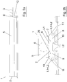
- Fig.3 shows a view obliquely from below of a preferred embodiment of the air treatment device 1, where some parts have been removed to more clearly show the essential elements of the invention.
- the actuator 12 On the chilled beam 2, the actuator 12 is arranged such that a linear movement of the actuator 12 can be transmitted to the two cover members 9, arranged on a respective wall portion 26 of the of the pressure box 5, see also Fig.2b .
- the actuator 12 is provided with a through shaft 23 which is slidably disposed. By that the actuator 12 displaces the shaft 23 along its length direction a linear movement will be accomplished, which movement is transmitted to the cover members 9 through an attachment 27 between the shaft 23 and cover members 9. Further, the actuator 12 is provided with a connection 25 to which one end of a measuring tube 22 is connected.
- the other end of the measuring tube 22 is connected to the pressure measuring socket 13 on the pressure box 5.
- the actuator 12 is arranged to register the static pressure in the pressure box 5 and further also adapted to register the physical position of the shaft 23, which position in turn corresponds to a k-factor corresponding with the open area of the outlets 7.
- Software 15 in the actuator converts the current physical location of the shaft 23 to the current k-factor and calculates the real/actual air flow in the chilled beam 2, by means of the actual static pressure in the pressure box 5.
- the actuator 12 also has adjustment means 28 in the form of set screws, which are used to set the minimum flow at non-presence, and further for setting within which air flows the supply air flow will vary when presence - from normal flow to maximum flow.
- the air flow is down regulated to minimum flow because the actual air flow in the chilled beam does not match the set point that apply to non-presence.
- the actuator 12 displaces the shaft 23 in the direction corresponding to a direction of movement for reduced flow, that is, so that the cover members 9 covers a larger part of the outlets 7, wherein the flow area is decreased.
- the system regulates the flow so that it is corresponding to the set point flow for non-presence.
- the fluid flow through the heat exchanger 10 can, depending on the control mode, be adjusted down to a minimum flow.
- the temperature and carbon dioxide values may have other limits than at presence mode.
- the supply air flow regulation because it is within the scope of the invention.
- the supply airflow is regulated up to a normal operation mode, and if the room temperature rises above the set point value, primarily an adjustment of the liquid flow can be done. But if that is not enough and/or the carbon dioxide level also is too high, the airflow is increased gradually to keep the comfort of the premises.
- Increased supply air flow L1 out of the pressure box 5 also leads to greater induction, at least up to certain levels, which also means that an increased circulating air flow L2 is drawn up through the heat exchanger 10 and conditioned by it.
- the actual supply airflow is balanced constantly towards current set point depending on the room condition, and the VAV regulation is individual and direct at the chilled beam 2, without any additional pressure drops beyond that yet available in the chilled beam, and the supply airflow to the premises A is really the correct.
Landscapes
- Engineering & Computer Science (AREA)
- Chemical & Material Sciences (AREA)
- Combustion & Propulsion (AREA)
- Mechanical Engineering (AREA)
- General Engineering & Computer Science (AREA)
- Physics & Mathematics (AREA)
- Fluid Mechanics (AREA)
- Life Sciences & Earth Sciences (AREA)
- Sustainable Development (AREA)
- Signal Processing (AREA)
- Fuzzy Systems (AREA)
- Mathematical Physics (AREA)
- Air Conditioning Control Device (AREA)
Claims (5)
- Luftbehandlungsvorrichtung (1) zum Steuern des Versorgungsluftflusses (L1) zu einer Räumlichkeit (A) und zur Konditionierung desselben, und wobei die Luftbehandlungsvorrichtung (1) einen gekühlten Träger (2) aufweist, der mit einem Versorgungsluftkanal (3) in einem Luftbehandlungssystem (4) verbunden ist, und wobei der gekühlte Träger (2) eine Druckbox (5) mit wenigstens einem Einlass (6) zum Einfließen des Versorgungsluftflusses (L1) von dem Versorgungsluftkanal (3) zu der Druckbox (5) aufweist, und mit einer Mehrzahl von Auslässen (7) zum Auslass des Versorgungsluftflusses (L1) aus der Druckbox (5) zu einer Mischkammer (8), und wobei die Auslässe (7) gemäß einer Konfiguration angeordnet sind, die veränderbar ist mittels wenigstens eines Deckelementes (9), das verschiebbar in Bezug auf die Auslässe (7) angeordnet ist, wobei ferner der gekühlte Träger (2) wenigstens einen flüssigmäßig gekoppelten Wärmetauscher (10) aufweist, der alternativ angeordnet ist, um einen durchfließenden Luftstrom mittels Wärmeaustausch zu kühlen oder zu heizen, und wobei durch den Wärmetauscher (10) ein Zirkulationsluftfluss (L2) dazu ausgebildet ist, von den Räumlichkeiten (A) infolge eines Induktionseffektes angetrieben durch den Durchlass des Versorgungsluftflusses (L1) aus den Auslässen (7) zu der Mischkammer (8) zu fließen, und wobei die Mischkammer (8) dazu angeordnet ist, den Versorgungsluftfluss (L1) und den durch den Wärmetauscher (10) konditionierten Zirkulationsluftfluss (L2) in einen gemeinsamen Luftstrom (L1 + L2) zu vereinigen und den Luftstrom (L1 + L2) zu wenigstens einer Auslassöffnung (11) zum Ausfluss zu den Räumlichkeiten (A) zu führen, und wobei die Luftbehandlungsvorrichtung (1) ferner wenigstens einen Aktuator (12) aufweist, um den Volumenfluss des Versorgungsluftflusses (L1) zu steuern, und wobei die Druckbox (5) ferner wenigstens einen Druckmesssockel (13) aufweist, der für eine repräsentative Kontrolle des statischen Druckes (ps) in der Druckbox verwendbar ist, und wobei das Luftbehandlungssystem (4) wenigstens einen Raumsensor (14) aufweist, der dazu angeordnet ist, die Raumbedingungen in den Räumlichkeiten (A) zu erfassen und dies zu dem Luftbehandlungssystem (4) zu kommunizieren, um die Luftbehandlungsvorrichtung (1) zu steuern, dadurch gekennzeichnet, dass die Luftbehandlungsvorrichtung (1) dazu angeordnet ist, den statischen Druck (ps) in der Druckbox (5) und die Position des Aktuators (12) zu erfassen und auf der Basis davon den realen Versorgungsluftfluss (L1) in dem gekühlten Träger (2) zu berechnen, und wobei der Aktuator (12) bei angezeigter Notwendigkeit dazu angeordnet ist, die Konfiguration der Auslässe (7) durch eine Linearbewegung des Deckelementes (9) zu verändern, durch welche Bewegung die offene Fläche der Auslässe (7) verändert wird, um den Versorgungsluftfluss (L1) durch Verschiebung des Deckelementes (9) zu verändern.
- Luftbehandlungsvorrichtung nach Anspruch 1, dadurch gekennzeichnet, dass der Aktuator (12) dazu angeordnet ist, den statischen Druck (ps) in der Druckbox (5) und die Position des Aktuators (12) zu erfassen, und ferner auf der Basis davon dazu ausgebildet ist, den realen Versorgungsluftfluss (L1) in dem gekühlten Träger (2) mittels einer Software (15) in dem Aktuator (12) zu berechnen.
- Luftbehandlungsvorrichtung nach Anspruch 1, dadurch gekennzeichnet, dass ein Drucksensor (16) dazu angeordnet ist, den statischen Druck (ps) in der Druckbox (5) zu erfassen, und dass der Aktuator (12) dazu angeordnet ist, auf der Basis davon und auf der Basis der Position des Aktuators (12) den realen Versorgungsluftfluss (L1) in den gekühlten Träger (2) mittels einer Software (15) in dem Aktuator (12) zu berechnen.
- Luftbehandlungsvorrichtung nach Anspruch 1, dadurch gekennzeichnet, dass das Luftbehandlungssystem (4) eine Software (15) aufweist, um den statischen Druck (ps) in der Druckbox (5) und die Position des Aktuators (12) zu erfassen, und wobei die Software (15) auf der Basis davon dazu ausgebildet ist, den realen Versorgungsluftfluss (L1) in den gekühlten Träger (2) zu berechnen.
- Verfahren zum Steuern eines Versorgungsluftflusses (L1) zu einer Räumlichkeit (A) und zur Konditionierung desselben, mit Hilfe einer Luftbehandlungsvorrichtung (1), die einen gekühlten Träger (2) aufweist, der mit einem Versorgungsluftkanal (3) in einem Luftbehandlungssystem (4) verbunden ist, und wobei der gekühlte Träger (2) eine Druckbox (5) mit wenigstens einem Einlass (6) zum Zufluss von einem Versorgungsluftfluss (L1) aus dem Versorgungsluftkanal (3) zu der Druckbox (5) und zu einer Mehrzahl von Auslässen (7) zum Ausfluss des Versorgungsluftflusses (L1) aus der Druckbox (5) zu einer Mischkammer (8) aufweist, und die Auslässe (7) gemäß einer Konfiguration angeordnet sind, die veränderbar ist, indem wenigstens ein Deckelement (9) verschiebbar in Bezug auf die Auslässe (7) angeordnet ist, wobei ferner der gekühlte Träger (2) wenigstens einen flüssigmäßig gekoppelten Wärmetauscher (10) aufweist, der alternativ dazu ausgebildet ist, einen durchfließenden Luftstrom durch Wärmeaustausch zu kühlen oder zu heizen, und durch den der Wärmetauscher (10) dazu ausgebildet ist, einen Zirkulationsluftfluss (L2) zu den Räumlichkeiten (A) infolge eines Induktionseffektes zu erzeugen, der durch den Luftdurchlass des Versorgungsluftflusses (L1) aus den Auslässen (7) zu der Mischkammer (8) angetrieben ist, und wobei die Mischkammer (8) dazu ausgebildet ist, den Versorgungsluftfluss (L1) und den von dem Wärmetauscher (10) konditionierten Zirkulationsluftfluss (L2) zu einem gemeinsamen Luftstrom (L1 + L2) zu vereinigen und den Luftstrom (L1 + L2) zu wenigstens einer Auslassöffnung (11) zum Ausfluss zu den Räumlichkeiten (A) zu führen, und wobei ferner die Luftbehandlungsvorrichtung (1) wenigstens einen Aktuator (12) zur Steuerung des Volumenflusses des Versorgungsluftflusses (L1) aufweist, und wobei die Druckbox (5) wenigstens einen Druckmesssockel (13) aufweist, der dazu nutzbar ist, eine repräsentative Kontrolle des statischen Druckes (ps) in der Druckbox (5) zu bewirken, und wobei das Luftbehandlungssystem (4) wenigstens einen Raumsensor (14) aufweist, der dazu ausgebildet ist, die Raumbedingungen in den Räumlichkeiten (A) zu erfassen und dies zu dem Luftbehandlungssystem (4) zur Steuerung der Luftbehandlungsvorrichtung (1) zu kommunizieren,
gekennzeichnet durch die folgenden Schritte:- Messen des statischen Druckes (ps) in der Druckbox (5),- Erfassen der Position des Aktuators (12), um die tatsächliche Konfiguration der Auslässe (7) zu bestimmen, was den aktuellen k-Faktor liefert,- Berechnen des realen Versorgungsluftflusses (L1) zu dem gekühlten Träger (2) auf der Basis des statischen Druckes (ps) in der Druckbox (5) und der Position des Aktuators (12),- Messen/Erfassen des aktuellen Status der Raumbedingungen in den Räumlichkeiten (A) mit Hilfe des Raumsensors (14),- Vergleichen des realen Versorgungsluftflusses (L1) mit einem Sollzustand für die aktuelle Raumbedingung,- bei detektierter Notwendigkeit Verändern der Konfiguration der Auslässe (7), indem der Aktuator (12) durch eine Linearbewegung des Deckelementes (9) das Deckelement (9) in Bezug auf die Auslässe (7) bewegt, um den Versorgungsluftfluss (L1) zu verändern, durch welche Bewegung die offene Fläche der Auslässe (7) der Ausfluss des Versorgungsluftflusses (L1) verändert wird.
Priority Applications (1)
| Application Number | Priority Date | Filing Date | Title |
|---|---|---|---|
| PL15776087T PL3117155T3 (pl) | 2014-04-08 | 2015-02-11 | Urządzenie i sposób regulowania przepływu powietrza nawiewanego w systemie do uzdatniania powietrza |
Applications Claiming Priority (2)
| Application Number | Priority Date | Filing Date | Title |
|---|---|---|---|
| SE1450434A SE537916C2 (sv) | 2014-04-08 | 2014-04-08 | Anordning och förfarande för reglering av ett tilluftsflödevid ett luftbehandlingssystem |
| PCT/SE2015/050160 WO2015156720A1 (en) | 2014-04-08 | 2015-02-11 | Device and method for controlling a supply air flow at an air treatment system |
Publications (3)
| Publication Number | Publication Date |
|---|---|
| EP3117155A1 EP3117155A1 (de) | 2017-01-18 |
| EP3117155A4 EP3117155A4 (de) | 2017-12-20 |
| EP3117155B1 true EP3117155B1 (de) | 2018-12-12 |
Family
ID=54288165
Family Applications (1)
| Application Number | Title | Priority Date | Filing Date |
|---|---|---|---|
| EP15776087.7A Active EP3117155B1 (de) | 2014-04-08 | 2015-02-11 | Vorrichtung und verfahren zur steuerung eines zuluftstroms bei einem luftaufbereitungssystem |
Country Status (10)
| Country | Link |
|---|---|
| US (1) | US9903605B2 (de) |
| EP (1) | EP3117155B1 (de) |
| KR (1) | KR102408073B1 (de) |
| DK (1) | DK3117155T3 (de) |
| LT (1) | LT3117155T (de) |
| PL (1) | PL3117155T3 (de) |
| RU (1) | RU2669746C2 (de) |
| SE (1) | SE537916C2 (de) |
| SG (1) | SG11201607696XA (de) |
| WO (1) | WO2015156720A1 (de) |
Families Citing this family (10)
| Publication number | Priority date | Publication date | Assignee | Title |
|---|---|---|---|---|
| SE540427C2 (sv) | 2015-09-17 | 2018-09-11 | Flaektgroup Sweden Ab | Anordning och förfarande för reglering av ett tilluftsflöde vid en komfortkassett |
| NL2018837B1 (nl) * | 2017-05-03 | 2018-11-14 | Nijburg Invest B V | Hybride klimaatplafond, plafond voorzien daarvan en werkwijze voor het beïnvloeden van een klimaat in een ruimte of gebouw |
| DE202017103113U1 (de) * | 2017-05-23 | 2017-07-31 | Erwin Müller GmbH | Decken-Klimatisierungsvorrichtung mit Tragkonstruktion |
| US10641515B2 (en) * | 2017-12-21 | 2020-05-05 | Rheem Manufacturing Company | Linearization of airflow through zone dampers of an HVAC system |
| SE542661C2 (en) | 2018-04-09 | 2020-06-23 | Swegon Operations Ab | AIR TERMINAL DEVICE FOR CONTROL OF AIR FLOW IN A VENTILATION SYSTEM |
| NO345103B1 (no) * | 2018-10-31 | 2020-09-28 | Trox Auranor Norge As | Kjølebaffel |
| SE545781C2 (en) * | 2019-04-01 | 2024-01-09 | Mikael Nutsos | Method for on line monitoring of air flow at air tenninals of a ventilation system |
| PL243607B1 (pl) * | 2020-01-13 | 2023-09-18 | Adamski Bartlomiej | Indukcyjny panel klimatyzacyjny |
| EP4217665A4 (de) * | 2020-08-20 | 2024-10-30 | Kaip Pty Ltd | Diffusoreinheit und verfahren zur diffusion eines luftstroms |
| SK9838Y1 (sk) | 2022-12-22 | 2023-08-23 | Systemair Production a.s. | Vzduchotechnická komora s nastaviteľným prvkom na reguláciu a/alebo smerovanie prietoku |
Citations (12)
| Publication number | Priority date | Publication date | Assignee | Title |
|---|---|---|---|---|
| EP1188992A2 (de) | 2000-09-13 | 2002-03-20 | ABB Fläkt AB | Luftbehandlung und Belüftungsvorrichtung |
| WO2002042691A1 (en) | 2000-11-24 | 2002-05-30 | Halton Oy | Supply air terminal device |
| WO2005053975A1 (de) | 2003-12-08 | 2005-06-16 | Belimo Holding Ag | Regelung des luftstroms in einem lüftungsrohr |
| WO2007079434A2 (en) | 2006-01-03 | 2007-07-12 | Karamanos John C | Limited loss laminar flow dampers for heating, ventilation, and air conditioning (hvac) systems |
| WO2008115138A1 (en) | 2007-03-19 | 2008-09-25 | Mikael Nutsos | Air terminal device with a flow indicator |
| US20080294291A1 (en) | 2007-05-24 | 2008-11-27 | Johnson Controls Technology Company | Building automation systems and methods for controlling interacting control loops |
| WO2010000077A1 (en) | 2008-07-03 | 2010-01-07 | Belimo Holding Ag | Actuator for hvac systems and method for operating the actuator |
| WO2010005386A1 (en) | 2008-07-10 | 2010-01-14 | Lindab Ab | Plenum box |
| WO2010090592A2 (en) | 2009-02-06 | 2010-08-12 | Lindab Ab | Supply air terminal device |
| WO2012123552A1 (de) | 2011-03-16 | 2012-09-20 | Ferrobotics Compliant Robot Technology Gmbh | Aktive handhabungsvorrichtung und verfahren für kontaktaufgaben |
| WO2013013334A2 (de) | 2012-10-01 | 2013-01-31 | Belimo Holding Ag | Weiterentwicklungen eines heizungs-, lüftungs- und klimasystems |
| WO2013136177A2 (en) | 2012-03-16 | 2013-09-19 | Oy Halton Group Ltd. | Chilled beam with multiple modes |
Family Cites Families (9)
| Publication number | Priority date | Publication date | Assignee | Title |
|---|---|---|---|---|
| JP3731397B2 (ja) | 1999-08-27 | 2006-01-05 | 三菱電機株式会社 | 送風機、空気調和装置、送風機の送風方法 |
| KR100483691B1 (ko) * | 2002-05-27 | 2005-04-18 | 주식회사 나라컨트롤 | 변풍량 공기조화장치 및 방법 |
| US7036559B2 (en) * | 2003-07-08 | 2006-05-02 | Daniel Stanimirovic | Fully articulated and comprehensive air and fluid distribution, metering, and control method and apparatus for primary movers, heat exchangers, and terminal flow devices |
| US9677777B2 (en) * | 2005-05-06 | 2017-06-13 | HVAC MFG, Inc. | HVAC system and zone control unit |
| KR100695933B1 (ko) * | 2005-06-08 | 2007-03-15 | 한국건설기술연구원 | 수-공기 겸용 중앙공기조화시스템에서의 외기 유인량제어장치 및 방법 |
| WO2008086489A2 (en) * | 2007-01-10 | 2008-07-17 | Karamanos John C | Embedded heat exchanger for heating, ventilation, and air conditioning (hvac) systems and methods |
| NL2002077C (nl) * | 2008-10-09 | 2010-04-12 | Cornelis Johannes Evers | Luchtbehandelingsconvector. |
| SE534353C2 (sv) * | 2009-10-02 | 2011-07-19 | Flaekt Woods Ab | Kylbaffel med VAV-funktion via reglerskena |
| WO2013116695A1 (en) * | 2012-02-02 | 2013-08-08 | Semco, Llc | Chilled beam pump module, system, and method |
-
2014
- 2014-04-08 SE SE1450434A patent/SE537916C2/sv active IP Right Maintenance
-
2015
- 2015-02-11 PL PL15776087T patent/PL3117155T3/pl unknown
- 2015-02-11 DK DK15776087.7T patent/DK3117155T3/en active
- 2015-02-11 RU RU2016137159A patent/RU2669746C2/ru active IP Right Revival
- 2015-02-11 EP EP15776087.7A patent/EP3117155B1/de active Active
- 2015-02-11 SG SG11201607696XA patent/SG11201607696XA/en unknown
- 2015-02-11 KR KR1020167031270A patent/KR102408073B1/ko active IP Right Grant
- 2015-02-11 LT LTEP15776087.7T patent/LT3117155T/lt unknown
- 2015-02-11 WO PCT/SE2015/050160 patent/WO2015156720A1/en active Application Filing
- 2015-02-11 US US15/128,146 patent/US9903605B2/en active Active
Patent Citations (12)
| Publication number | Priority date | Publication date | Assignee | Title |
|---|---|---|---|---|
| EP1188992A2 (de) | 2000-09-13 | 2002-03-20 | ABB Fläkt AB | Luftbehandlung und Belüftungsvorrichtung |
| WO2002042691A1 (en) | 2000-11-24 | 2002-05-30 | Halton Oy | Supply air terminal device |
| WO2005053975A1 (de) | 2003-12-08 | 2005-06-16 | Belimo Holding Ag | Regelung des luftstroms in einem lüftungsrohr |
| WO2007079434A2 (en) | 2006-01-03 | 2007-07-12 | Karamanos John C | Limited loss laminar flow dampers for heating, ventilation, and air conditioning (hvac) systems |
| WO2008115138A1 (en) | 2007-03-19 | 2008-09-25 | Mikael Nutsos | Air terminal device with a flow indicator |
| US20080294291A1 (en) | 2007-05-24 | 2008-11-27 | Johnson Controls Technology Company | Building automation systems and methods for controlling interacting control loops |
| WO2010000077A1 (en) | 2008-07-03 | 2010-01-07 | Belimo Holding Ag | Actuator for hvac systems and method for operating the actuator |
| WO2010005386A1 (en) | 2008-07-10 | 2010-01-14 | Lindab Ab | Plenum box |
| WO2010090592A2 (en) | 2009-02-06 | 2010-08-12 | Lindab Ab | Supply air terminal device |
| WO2012123552A1 (de) | 2011-03-16 | 2012-09-20 | Ferrobotics Compliant Robot Technology Gmbh | Aktive handhabungsvorrichtung und verfahren für kontaktaufgaben |
| WO2013136177A2 (en) | 2012-03-16 | 2013-09-19 | Oy Halton Group Ltd. | Chilled beam with multiple modes |
| WO2013013334A2 (de) | 2012-10-01 | 2013-01-31 | Belimo Holding Ag | Weiterentwicklungen eines heizungs-, lüftungs- und klimasystems |
Non-Patent Citations (8)
| Title |
|---|
| ANONYMOUS: "Injusteringshandbok", FLÄKT WOODS AB, February 2012 (2012-02-01), pages 3 - 122, XP055642018 |
| ANONYMOUS: "Plexus active chilled beam with adjustable air volume control / Frenger Systems Limited", INTERNET ARCHIVE WAYBACK MACHINE, 4 July 2012 (2012-07-04), pages 1 - 16, XP055642002, Retrieved from the Internet <URL:https://web.archive.org/web/20120704014748/http://www.frenger.co.uk/Documents/Literature/LTPlexus.pdf> |
| ANONYMOUS: "Plexus Operation & Maintenance V1.7 / Frenger Systems Limited", PLEXUS OPERATION & MAINTENANCE, 4 July 2011 (2011-07-04), pages 1 - 23, XP055641981, Retrieved from the Internet <URL:https://web.archive.org/web/20120704014819if_/http://www.frenger.co.uk:80/Documents/O&M%20Manuals/OM_Plexus.pdf> |
| ANONYMOUS: "Plexus Service & Maintenance", LINDAB, 3 May 2013 (2013-05-03), pages 1 - 14, XP055641980 |
| ANONYMOUS: "Plexus", LINDAB, 28 August 2013 (2013-08-28), pages 1 - 22, XP055641990 |
| ANONYMOUS: "Supply air beam / Plexus", LINDAB VENTILATION A/S, August 2012 (2012-08-01), pages 79 - 103, XP055642006 |
| FLÄKT WOODS: "Flexibel kylbaffel", HUSBYGGAREN, no. 2, 2012, pages 81, XP055642021 |
| FLÄKT WOODS: "Innehall STRA-14 för kylbafflar", STRA-14 RUMSREGULATOR: MONTERINGS-OCH SKÖTSELINSTRUKTION, February 2014 (2014-02-01), pages 1 - 14, XP055642023 |
Also Published As
| Publication number | Publication date |
|---|---|
| SE537916C2 (sv) | 2015-11-24 |
| RU2016137159A (ru) | 2018-03-21 |
| RU2669746C2 (ru) | 2018-10-15 |
| KR20160142880A (ko) | 2016-12-13 |
| KR102408073B1 (ko) | 2022-06-13 |
| PL3117155T3 (pl) | 2019-05-31 |
| WO2015156720A1 (en) | 2015-10-15 |
| EP3117155A1 (de) | 2017-01-18 |
| EP3117155A4 (de) | 2017-12-20 |
| SE1450434A1 (sv) | 2015-10-09 |
| SG11201607696XA (en) | 2016-10-28 |
| DK3117155T3 (en) | 2019-01-28 |
| LT3117155T (lt) | 2019-01-25 |
| US20170122611A1 (en) | 2017-05-04 |
| US9903605B2 (en) | 2018-02-27 |
| RU2016137159A3 (de) | 2018-08-03 |
Similar Documents
| Publication | Publication Date | Title |
|---|---|---|
| EP3117155B1 (de) | Vorrichtung und verfahren zur steuerung eines zuluftstroms bei einem luftaufbereitungssystem | |
| CA3014479C (en) | Integrated heat and energy recovery ventilator system | |
| WO2017002245A1 (ja) | 空調システム制御装置及び空調システム | |
| US9982955B2 (en) | Method for operating a heat exchanger using temperature measurements to determine saturation level | |
| US20180363933A1 (en) | Zoning System for Air Conditioning (HVAC) Equipment | |
| US20120193066A1 (en) | Fan coil air conditioning system, a fan coil unit, and a method of controlling a fan coil air conditioning syst | |
| JP2018109458A (ja) | 空調システム用の制御装置、空調システム | |
| SE508633C3 (sv) | Blandningsdel foer inloppsluft och aaterfoeringsluft i en luftkonditioneringsapparat | |
| US3927827A (en) | Method for controlling the ventilation of an air-conditioning system | |
| KR102104054B1 (ko) | 실내 상황에 적응하여 풍량 조절하는 공조 시스템 | |
| EP2828584A1 (de) | Modulare luftbewegungsvorrichtung | |
| JPH0317284B2 (de) | ||
| JP2018109459A (ja) | 空調システム用の制御装置、空調システム | |
| KR100728316B1 (ko) | 가변풍량방식 공조 제어시스템 | |
| US2123440A (en) | Air conditioning system | |
| WO2020091603A1 (en) | Chilled beam | |
| KR101144147B1 (ko) | 자동압력대응방식의 전기전자식 디퓨져 | |
| US5373987A (en) | Variable volume air valve | |
| US20180187904A1 (en) | Device and method for controlling a supply air flow at a comfort cassette | |
| JP2661299B2 (ja) | 空気調和機 | |
| JP5919045B2 (ja) | 空気調和装置 | |
| KR101941429B1 (ko) | 이산화탄소 농도 측정 기능을 갖는 열교환 환기장치 | |
| JP2005127636A (ja) | 空調システムおよび空調方法 | |
| RU2778847C1 (ru) | Способ распределения воздуха | |
| RU2607883C1 (ru) | Механическая регулируемая система вентиляции |
Legal Events
| Date | Code | Title | Description |
|---|---|---|---|
| STAA | Information on the status of an ep patent application or granted ep patent |
Free format text: STATUS: THE INTERNATIONAL PUBLICATION HAS BEEN MADE |
|
| PUAI | Public reference made under article 153(3) epc to a published international application that has entered the european phase |
Free format text: ORIGINAL CODE: 0009012 |
|
| STAA | Information on the status of an ep patent application or granted ep patent |
Free format text: STATUS: REQUEST FOR EXAMINATION WAS MADE |
|
| 17P | Request for examination filed |
Effective date: 20160920 |
|
| AK | Designated contracting states |
Kind code of ref document: A1 Designated state(s): AL AT BE BG CH CY CZ DE DK EE ES FI FR GB GR HR HU IE IS IT LI LT LU LV MC MK MT NL NO PL PT RO RS SE SI SK SM TR |
|
| AX | Request for extension of the european patent |
Extension state: BA ME |
|
| DAX | Request for extension of the european patent (deleted) | ||
| A4 | Supplementary search report drawn up and despatched |
Effective date: 20171116 |
|
| RIC1 | Information provided on ipc code assigned before grant |
Ipc: F24F 5/00 20060101ALN20171110BHEP Ipc: F24F 11/04 20060101ALI20171110BHEP Ipc: F24F 13/12 20060101ALI20171110BHEP Ipc: F24F 1/01 20110101AFI20171110BHEP |
|
| RAP1 | Party data changed (applicant data changed or rights of an application transferred) |
Owner name: FLAEKTGROUP SWEDEN AB |
|
| GRAP | Despatch of communication of intention to grant a patent |
Free format text: ORIGINAL CODE: EPIDOSNIGR1 |
|
| STAA | Information on the status of an ep patent application or granted ep patent |
Free format text: STATUS: GRANT OF PATENT IS INTENDED |
|
| RIC1 | Information provided on ipc code assigned before grant |
Ipc: F24F 13/12 20060101ALI20180626BHEP Ipc: F24F 11/70 20180101ALI20180626BHEP Ipc: F24F 5/00 20060101ALN20180626BHEP Ipc: F24F 11/30 20180101ALN20180626BHEP Ipc: F24F 11/74 20180101ALI20180626BHEP Ipc: F24F 1/01 20110101AFI20180626BHEP Ipc: F24F 3/00 20060101ALN20180626BHEP |
|
| INTG | Intention to grant announced |
Effective date: 20180720 |
|
| GRAS | Grant fee paid |
Free format text: ORIGINAL CODE: EPIDOSNIGR3 |
|
| GRAA | (expected) grant |
Free format text: ORIGINAL CODE: 0009210 |
|
| STAA | Information on the status of an ep patent application or granted ep patent |
Free format text: STATUS: THE PATENT HAS BEEN GRANTED |
|
| AK | Designated contracting states |
Kind code of ref document: B1 Designated state(s): AL AT BE BG CH CY CZ DE DK EE ES FI FR GB GR HR HU IE IS IT LI LT LU LV MC MK MT NL NO PL PT RO RS SE SI SK SM TR |
|
| REG | Reference to a national code |
Ref country code: GB Ref legal event code: FG4D |
|
| REG | Reference to a national code |
Ref country code: CH Ref legal event code: EP |
|
| REG | Reference to a national code |
Ref country code: AT Ref legal event code: REF Ref document number: 1076540 Country of ref document: AT Kind code of ref document: T Effective date: 20181215 |
|
| REG | Reference to a national code |
Ref country code: DE Ref legal event code: R096 Ref document number: 602015021475 Country of ref document: DE |
|
| REG | Reference to a national code |
Ref country code: IE Ref legal event code: FG4D |
|
| REG | Reference to a national code |
Ref country code: DK Ref legal event code: T3 Effective date: 20190122 |
|
| REG | Reference to a national code |
Ref country code: SE Ref legal event code: TRGR |
|
| REG | Reference to a national code |
Ref country code: NL Ref legal event code: FP |
|
| REG | Reference to a national code |
Ref country code: NO Ref legal event code: T2 Effective date: 20181212 |
|
| PG25 | Lapsed in a contracting state [announced via postgrant information from national office to epo] |
Ref country code: ES Free format text: LAPSE BECAUSE OF FAILURE TO SUBMIT A TRANSLATION OF THE DESCRIPTION OR TO PAY THE FEE WITHIN THE PRESCRIBED TIME-LIMIT Effective date: 20181212 Ref country code: LV Free format text: LAPSE BECAUSE OF FAILURE TO SUBMIT A TRANSLATION OF THE DESCRIPTION OR TO PAY THE FEE WITHIN THE PRESCRIBED TIME-LIMIT Effective date: 20181212 Ref country code: HR Free format text: LAPSE BECAUSE OF FAILURE TO SUBMIT A TRANSLATION OF THE DESCRIPTION OR TO PAY THE FEE WITHIN THE PRESCRIBED TIME-LIMIT Effective date: 20181212 Ref country code: BG Free format text: LAPSE BECAUSE OF FAILURE TO SUBMIT A TRANSLATION OF THE DESCRIPTION OR TO PAY THE FEE WITHIN THE PRESCRIBED TIME-LIMIT Effective date: 20190312 |
|
| REG | Reference to a national code |
Ref country code: AT Ref legal event code: MK05 Ref document number: 1076540 Country of ref document: AT Kind code of ref document: T Effective date: 20181212 |
|
| PG25 | Lapsed in a contracting state [announced via postgrant information from national office to epo] |
Ref country code: RS Free format text: LAPSE BECAUSE OF FAILURE TO SUBMIT A TRANSLATION OF THE DESCRIPTION OR TO PAY THE FEE WITHIN THE PRESCRIBED TIME-LIMIT Effective date: 20181212 Ref country code: GR Free format text: LAPSE BECAUSE OF FAILURE TO SUBMIT A TRANSLATION OF THE DESCRIPTION OR TO PAY THE FEE WITHIN THE PRESCRIBED TIME-LIMIT Effective date: 20190313 Ref country code: AL Free format text: LAPSE BECAUSE OF FAILURE TO SUBMIT A TRANSLATION OF THE DESCRIPTION OR TO PAY THE FEE WITHIN THE PRESCRIBED TIME-LIMIT Effective date: 20181212 |
|
| PG25 | Lapsed in a contracting state [announced via postgrant information from national office to epo] |
Ref country code: PT Free format text: LAPSE BECAUSE OF FAILURE TO SUBMIT A TRANSLATION OF THE DESCRIPTION OR TO PAY THE FEE WITHIN THE PRESCRIBED TIME-LIMIT Effective date: 20190412 |
|
| PG25 | Lapsed in a contracting state [announced via postgrant information from national office to epo] |
Ref country code: RO Free format text: LAPSE BECAUSE OF FAILURE TO SUBMIT A TRANSLATION OF THE DESCRIPTION OR TO PAY THE FEE WITHIN THE PRESCRIBED TIME-LIMIT Effective date: 20181212 Ref country code: IS Free format text: LAPSE BECAUSE OF FAILURE TO SUBMIT A TRANSLATION OF THE DESCRIPTION OR TO PAY THE FEE WITHIN THE PRESCRIBED TIME-LIMIT Effective date: 20190412 Ref country code: SK Free format text: LAPSE BECAUSE OF FAILURE TO SUBMIT A TRANSLATION OF THE DESCRIPTION OR TO PAY THE FEE WITHIN THE PRESCRIBED TIME-LIMIT Effective date: 20181212 Ref country code: SM Free format text: LAPSE BECAUSE OF FAILURE TO SUBMIT A TRANSLATION OF THE DESCRIPTION OR TO PAY THE FEE WITHIN THE PRESCRIBED TIME-LIMIT Effective date: 20181212 Ref country code: EE Free format text: LAPSE BECAUSE OF FAILURE TO SUBMIT A TRANSLATION OF THE DESCRIPTION OR TO PAY THE FEE WITHIN THE PRESCRIBED TIME-LIMIT Effective date: 20181212 |
|
| REG | Reference to a national code |
Ref country code: DE Ref legal event code: R026 Ref document number: 602015021475 Country of ref document: DE |
|
| PLBI | Opposition filed |
Free format text: ORIGINAL CODE: 0009260 |
|
| PLAX | Notice of opposition and request to file observation + time limit sent |
Free format text: ORIGINAL CODE: EPIDOSNOBS2 |
|
| REG | Reference to a national code |
Ref country code: CH Ref legal event code: PL |
|
| 26 | Opposition filed |
Opponent name: LINDAB AB Effective date: 20190912 Opponent name: SWEGON OPERATIONS AB Effective date: 20190912 |
|
| PG25 | Lapsed in a contracting state [announced via postgrant information from national office to epo] |
Ref country code: SI Free format text: LAPSE BECAUSE OF FAILURE TO SUBMIT A TRANSLATION OF THE DESCRIPTION OR TO PAY THE FEE WITHIN THE PRESCRIBED TIME-LIMIT Effective date: 20181212 Ref country code: AT Free format text: LAPSE BECAUSE OF FAILURE TO SUBMIT A TRANSLATION OF THE DESCRIPTION OR TO PAY THE FEE WITHIN THE PRESCRIBED TIME-LIMIT Effective date: 20181212 Ref country code: MC Free format text: LAPSE BECAUSE OF FAILURE TO SUBMIT A TRANSLATION OF THE DESCRIPTION OR TO PAY THE FEE WITHIN THE PRESCRIBED TIME-LIMIT Effective date: 20181212 |
|
| PG25 | Lapsed in a contracting state [announced via postgrant information from national office to epo] |
Ref country code: LI Free format text: LAPSE BECAUSE OF NON-PAYMENT OF DUE FEES Effective date: 20190228 Ref country code: CH Free format text: LAPSE BECAUSE OF NON-PAYMENT OF DUE FEES Effective date: 20190228 |
|
| PLBB | Reply of patent proprietor to notice(s) of opposition received |
Free format text: ORIGINAL CODE: EPIDOSNOBS3 |
|
| PG25 | Lapsed in a contracting state [announced via postgrant information from national office to epo] |
Ref country code: TR Free format text: LAPSE BECAUSE OF FAILURE TO SUBMIT A TRANSLATION OF THE DESCRIPTION OR TO PAY THE FEE WITHIN THE PRESCRIBED TIME-LIMIT Effective date: 20181212 |
|
| PG25 | Lapsed in a contracting state [announced via postgrant information from national office to epo] |
Ref country code: MT Free format text: LAPSE BECAUSE OF NON-PAYMENT OF DUE FEES Effective date: 20190211 |
|
| RDAF | Communication despatched that patent is revoked |
Free format text: ORIGINAL CODE: EPIDOSNREV1 |
|
| APBM | Appeal reference recorded |
Free format text: ORIGINAL CODE: EPIDOSNREFNO |
|
| APBP | Date of receipt of notice of appeal recorded |
Free format text: ORIGINAL CODE: EPIDOSNNOA2O |
|
| PG25 | Lapsed in a contracting state [announced via postgrant information from national office to epo] |
Ref country code: CY Free format text: LAPSE BECAUSE OF FAILURE TO SUBMIT A TRANSLATION OF THE DESCRIPTION OR TO PAY THE FEE WITHIN THE PRESCRIBED TIME-LIMIT Effective date: 20181212 |
|
| APAH | Appeal reference modified |
Free format text: ORIGINAL CODE: EPIDOSCREFNO |
|
| PG25 | Lapsed in a contracting state [announced via postgrant information from national office to epo] |
Ref country code: HU Free format text: LAPSE BECAUSE OF FAILURE TO SUBMIT A TRANSLATION OF THE DESCRIPTION OR TO PAY THE FEE WITHIN THE PRESCRIBED TIME-LIMIT; INVALID AB INITIO Effective date: 20150211 |
|
| APBQ | Date of receipt of statement of grounds of appeal recorded |
Free format text: ORIGINAL CODE: EPIDOSNNOA3O |
|
| REG | Reference to a national code |
Ref country code: CH Ref legal event code: PK Free format text: BERICHTIGUNGEN |
|
| RIC2 | Information provided on ipc code assigned after grant |
Ipc: F24F 11/30 20180101ALI20210809BHEP Ipc: F24F 3/00 20060101ALI20210809BHEP Ipc: F24F 5/00 20060101ALI20210809BHEP Ipc: F24F 11/74 20180101ALI20210809BHEP Ipc: F24F 13/12 20060101ALI20210809BHEP Ipc: F24F 11/70 20180101ALI20210809BHEP Ipc: F24F 1/01 20110101AFI20210809BHEP |
|
| PLAB | Opposition data, opponent's data or that of the opponent's representative modified |
Free format text: ORIGINAL CODE: 0009299OPPO |
|
| R26 | Opposition filed (corrected) |
Opponent name: LINDAB AB Effective date: 20190912 |
|
| PG25 | Lapsed in a contracting state [announced via postgrant information from national office to epo] |
Ref country code: MK Free format text: LAPSE BECAUSE OF FAILURE TO SUBMIT A TRANSLATION OF THE DESCRIPTION OR TO PAY THE FEE WITHIN THE PRESCRIBED TIME-LIMIT Effective date: 20181212 |
|
| REG | Reference to a national code |
Ref country code: DE Ref legal event code: R100 Ref document number: 602015021475 Country of ref document: DE |
|
| APBU | Appeal procedure closed |
Free format text: ORIGINAL CODE: EPIDOSNNOA9O |
|
| PLCK | Communication despatched that opposition was rejected |
Free format text: ORIGINAL CODE: EPIDOSNREJ1 |
|
| STAA | Information on the status of an ep patent application or granted ep patent |
Free format text: STATUS: OPPOSITION REJECTED |
|
| PLBN | Opposition rejected |
Free format text: ORIGINAL CODE: 0009273 |
|
| 27O | Opposition rejected |
Effective date: 20230503 |
|
| PGFP | Annual fee paid to national office [announced via postgrant information from national office to epo] |
Ref country code: LU Payment date: 20240216 Year of fee payment: 10 |
|
| PGFP | Annual fee paid to national office [announced via postgrant information from national office to epo] |
Ref country code: LT Payment date: 20240124 Year of fee payment: 10 |
|
| PGFP | Annual fee paid to national office [announced via postgrant information from national office to epo] |
Ref country code: IE Payment date: 20240216 Year of fee payment: 10 Ref country code: NL Payment date: 20240216 Year of fee payment: 10 |
|
| PGFP | Annual fee paid to national office [announced via postgrant information from national office to epo] |
Ref country code: FI Payment date: 20240220 Year of fee payment: 10 Ref country code: DE Payment date: 20240219 Year of fee payment: 10 Ref country code: CZ Payment date: 20240112 Year of fee payment: 10 Ref country code: GB Payment date: 20240216 Year of fee payment: 10 |
|
| PGFP | Annual fee paid to national office [announced via postgrant information from national office to epo] |
Ref country code: SE Payment date: 20240219 Year of fee payment: 10 Ref country code: PL Payment date: 20240113 Year of fee payment: 10 Ref country code: NO Payment date: 20240221 Year of fee payment: 10 Ref country code: IT Payment date: 20240219 Year of fee payment: 10 Ref country code: FR Payment date: 20240215 Year of fee payment: 10 Ref country code: DK Payment date: 20240219 Year of fee payment: 10 Ref country code: BE Payment date: 20240216 Year of fee payment: 10 |