EP3115753A1 - System und verfahren für nicht-intrusive und kontinuierliche füllstandsmessung einer flüssigkeitsspezifikation - Google Patents
System und verfahren für nicht-intrusive und kontinuierliche füllstandsmessung einer flüssigkeitsspezifikation Download PDFInfo
- Publication number
- EP3115753A1 EP3115753A1 EP15195777.6A EP15195777A EP3115753A1 EP 3115753 A1 EP3115753 A1 EP 3115753A1 EP 15195777 A EP15195777 A EP 15195777A EP 3115753 A1 EP3115753 A1 EP 3115753A1
- Authority
- EP
- European Patent Office
- Prior art keywords
- wave
- liquid
- wall
- transmitter
- vessel
- Prior art date
- Legal status (The legal status is an assumption and is not a legal conclusion. Google has not performed a legal analysis and makes no representation as to the accuracy of the status listed.)
- Granted
Links
- 239000007788 liquid Substances 0.000 title claims abstract description 148
- 238000005259 measurement Methods 0.000 title claims abstract description 28
- 238000000034 method Methods 0.000 title claims abstract description 27
- 235000019687 Lamb Nutrition 0.000 claims abstract description 73
- 238000002604 ultrasonography Methods 0.000 claims abstract description 25
- 239000007787 solid Substances 0.000 claims abstract description 7
- 239000000463 material Substances 0.000 claims description 19
- 229910000831 Steel Inorganic materials 0.000 description 6
- 229910052782 aluminium Inorganic materials 0.000 description 6
- XAGFODPZIPBFFR-UHFFFAOYSA-N aluminium Chemical compound [Al] XAGFODPZIPBFFR-UHFFFAOYSA-N 0.000 description 6
- 239000010959 steel Substances 0.000 description 6
- 230000001902 propagating effect Effects 0.000 description 5
- 230000006399 behavior Effects 0.000 description 4
- 230000001419 dependent effect Effects 0.000 description 4
- 238000009434 installation Methods 0.000 description 4
- 230000005855 radiation Effects 0.000 description 4
- 238000005516 engineering process Methods 0.000 description 3
- 238000000691 measurement method Methods 0.000 description 3
- 229910052751 metal Inorganic materials 0.000 description 3
- 239000002184 metal Substances 0.000 description 3
- 150000002739 metals Chemical class 0.000 description 3
- PAYRUJLWNCNPSJ-UHFFFAOYSA-N Aniline Chemical compound NC1=CC=CC=C1 PAYRUJLWNCNPSJ-UHFFFAOYSA-N 0.000 description 2
- 229910001374 Invar Inorganic materials 0.000 description 2
- 239000013590 bulk material Substances 0.000 description 2
- 238000013016 damping Methods 0.000 description 2
- 230000007423 decrease Effects 0.000 description 2
- 238000001514 detection method Methods 0.000 description 2
- 229920002635 polyurethane Polymers 0.000 description 2
- 239000004814 polyurethane Substances 0.000 description 2
- 238000002310 reflectometry Methods 0.000 description 2
- 239000000126 substance Substances 0.000 description 2
- OKTJSMMVPCPJKN-UHFFFAOYSA-N Carbon Chemical compound [C] OKTJSMMVPCPJKN-UHFFFAOYSA-N 0.000 description 1
- 229910000640 Fe alloy Inorganic materials 0.000 description 1
- 229910000990 Ni alloy Inorganic materials 0.000 description 1
- 230000000903 blocking effect Effects 0.000 description 1
- 229910052799 carbon Inorganic materials 0.000 description 1
- 238000011109 contamination Methods 0.000 description 1
- 230000003247 decreasing effect Effects 0.000 description 1
- 238000010586 diagram Methods 0.000 description 1
- 230000000694 effects Effects 0.000 description 1
- 230000005284 excitation Effects 0.000 description 1
- 239000002360 explosive Substances 0.000 description 1
- 235000013305 food Nutrition 0.000 description 1
- 230000006870 function Effects 0.000 description 1
- 230000005251 gamma ray Effects 0.000 description 1
- 239000000203 mixture Substances 0.000 description 1
- 230000000704 physical effect Effects 0.000 description 1
- XLYOFNOQVPJJNP-UHFFFAOYSA-N water Substances O XLYOFNOQVPJJNP-UHFFFAOYSA-N 0.000 description 1
Images


Classifications
-
- G—PHYSICS
- G01—MEASURING; TESTING
- G01F—MEASURING VOLUME, VOLUME FLOW, MASS FLOW OR LIQUID LEVEL; METERING BY VOLUME
- G01F23/00—Indicating or measuring liquid level or level of fluent solid material, e.g. indicating in terms of volume or indicating by means of an alarm
- G01F23/22—Indicating or measuring liquid level or level of fluent solid material, e.g. indicating in terms of volume or indicating by means of an alarm by measuring physical variables, other than linear dimensions, pressure or weight, dependent on the level to be measured, e.g. by difference of heat transfer of steam or water
- G01F23/28—Indicating or measuring liquid level or level of fluent solid material, e.g. indicating in terms of volume or indicating by means of an alarm by measuring physical variables, other than linear dimensions, pressure or weight, dependent on the level to be measured, e.g. by difference of heat transfer of steam or water by measuring the variations of parameters of electromagnetic or acoustic waves applied directly to the liquid or fluent solid material
- G01F23/296—Acoustic waves
- G01F23/2962—Measuring transit time of reflected waves
-
- G—PHYSICS
- G01—MEASURING; TESTING
- G01N—INVESTIGATING OR ANALYSING MATERIALS BY DETERMINING THEIR CHEMICAL OR PHYSICAL PROPERTIES
- G01N29/00—Investigating or analysing materials by the use of ultrasonic, sonic or infrasonic waves; Visualisation of the interior of objects by transmitting ultrasonic or sonic waves through the object
- G01N29/02—Analysing fluids
- G01N29/024—Analysing fluids by measuring propagation velocity or propagation time of acoustic waves
-
- G—PHYSICS
- G01—MEASURING; TESTING
- G01N—INVESTIGATING OR ANALYSING MATERIALS BY DETERMINING THEIR CHEMICAL OR PHYSICAL PROPERTIES
- G01N29/00—Investigating or analysing materials by the use of ultrasonic, sonic or infrasonic waves; Visualisation of the interior of objects by transmitting ultrasonic or sonic waves through the object
- G01N29/22—Details, e.g. general constructional or apparatus details
- G01N29/222—Constructional or flow details for analysing fluids
-
- G—PHYSICS
- G01—MEASURING; TESTING
- G01S—RADIO DIRECTION-FINDING; RADIO NAVIGATION; DETERMINING DISTANCE OR VELOCITY BY USE OF RADIO WAVES; LOCATING OR PRESENCE-DETECTING BY USE OF THE REFLECTION OR RERADIATION OF RADIO WAVES; ANALOGOUS ARRANGEMENTS USING OTHER WAVES
- G01S15/00—Systems using the reflection or reradiation of acoustic waves, e.g. sonar systems
- G01S15/003—Bistatic sonar systems; Multistatic sonar systems
-
- G—PHYSICS
- G01—MEASURING; TESTING
- G01S—RADIO DIRECTION-FINDING; RADIO NAVIGATION; DETERMINING DISTANCE OR VELOCITY BY USE OF RADIO WAVES; LOCATING OR PRESENCE-DETECTING BY USE OF THE REFLECTION OR RERADIATION OF RADIO WAVES; ANALOGOUS ARRANGEMENTS USING OTHER WAVES
- G01S15/00—Systems using the reflection or reradiation of acoustic waves, e.g. sonar systems
- G01S15/02—Systems using the reflection or reradiation of acoustic waves, e.g. sonar systems using reflection of acoustic waves
- G01S15/06—Systems determining the position data of a target
- G01S15/08—Systems for measuring distance only
- G01S15/32—Systems for measuring distance only using transmission of continuous waves, whether amplitude-, frequency-, or phase-modulated, or unmodulated
-
- G—PHYSICS
- G01—MEASURING; TESTING
- G01S—RADIO DIRECTION-FINDING; RADIO NAVIGATION; DETERMINING DISTANCE OR VELOCITY BY USE OF RADIO WAVES; LOCATING OR PRESENCE-DETECTING BY USE OF THE REFLECTION OR RERADIATION OF RADIO WAVES; ANALOGOUS ARRANGEMENTS USING OTHER WAVES
- G01S15/00—Systems using the reflection or reradiation of acoustic waves, e.g. sonar systems
- G01S15/88—Sonar systems specially adapted for specific applications
-
- G—PHYSICS
- G01—MEASURING; TESTING
- G01S—RADIO DIRECTION-FINDING; RADIO NAVIGATION; DETERMINING DISTANCE OR VELOCITY BY USE OF RADIO WAVES; LOCATING OR PRESENCE-DETECTING BY USE OF THE REFLECTION OR RERADIATION OF RADIO WAVES; ANALOGOUS ARRANGEMENTS USING OTHER WAVES
- G01S7/00—Details of systems according to groups G01S13/00, G01S15/00, G01S17/00
- G01S7/52—Details of systems according to groups G01S13/00, G01S15/00, G01S17/00 of systems according to group G01S15/00
- G01S7/52004—Means for monitoring or calibrating
-
- G—PHYSICS
- G01—MEASURING; TESTING
- G01S—RADIO DIRECTION-FINDING; RADIO NAVIGATION; DETERMINING DISTANCE OR VELOCITY BY USE OF RADIO WAVES; LOCATING OR PRESENCE-DETECTING BY USE OF THE REFLECTION OR RERADIATION OF RADIO WAVES; ANALOGOUS ARRANGEMENTS USING OTHER WAVES
- G01S7/00—Details of systems according to groups G01S13/00, G01S15/00, G01S17/00
- G01S7/52—Details of systems according to groups G01S13/00, G01S15/00, G01S17/00 of systems according to group G01S15/00
- G01S7/534—Details of non-pulse systems
- G01S7/536—Extracting wanted echo signals
-
- G—PHYSICS
- G01—MEASURING; TESTING
- G01S—RADIO DIRECTION-FINDING; RADIO NAVIGATION; DETERMINING DISTANCE OR VELOCITY BY USE OF RADIO WAVES; LOCATING OR PRESENCE-DETECTING BY USE OF THE REFLECTION OR RERADIATION OF RADIO WAVES; ANALOGOUS ARRANGEMENTS USING OTHER WAVES
- G01S7/00—Details of systems according to groups G01S13/00, G01S15/00, G01S17/00
- G01S7/52—Details of systems according to groups G01S13/00, G01S15/00, G01S17/00 of systems according to group G01S15/00
- G01S7/539—Details of systems according to groups G01S13/00, G01S15/00, G01S17/00 of systems according to group G01S15/00 using analysis of echo signal for target characterisation; Target signature; Target cross-section
-
- G—PHYSICS
- G01—MEASURING; TESTING
- G01B—MEASURING LENGTH, THICKNESS OR SIMILAR LINEAR DIMENSIONS; MEASURING ANGLES; MEASURING AREAS; MEASURING IRREGULARITIES OF SURFACES OR CONTOURS
- G01B17/00—Measuring arrangements characterised by the use of infrasonic, sonic or ultrasonic vibrations
-
- G—PHYSICS
- G01—MEASURING; TESTING
- G01H—MEASUREMENT OF MECHANICAL VIBRATIONS OR ULTRASONIC, SONIC OR INFRASONIC WAVES
- G01H5/00—Measuring propagation velocity of ultrasonic, sonic or infrasonic waves, e.g. of pressure waves
-
- G—PHYSICS
- G01—MEASURING; TESTING
- G01N—INVESTIGATING OR ANALYSING MATERIALS BY DETERMINING THEIR CHEMICAL OR PHYSICAL PROPERTIES
- G01N2291/00—Indexing codes associated with group G01N29/00
- G01N2291/01—Indexing codes associated with the measuring variable
- G01N2291/011—Velocity or travel time
-
- G—PHYSICS
- G01—MEASURING; TESTING
- G01N—INVESTIGATING OR ANALYSING MATERIALS BY DETERMINING THEIR CHEMICAL OR PHYSICAL PROPERTIES
- G01N2291/00—Indexing codes associated with group G01N29/00
- G01N2291/02—Indexing codes associated with the analysed material
- G01N2291/028—Material parameters
- G01N2291/02836—Flow rate, liquid level
-
- G—PHYSICS
- G01—MEASURING; TESTING
- G01N—INVESTIGATING OR ANALYSING MATERIALS BY DETERMINING THEIR CHEMICAL OR PHYSICAL PROPERTIES
- G01N2291/00—Indexing codes associated with group G01N29/00
- G01N2291/02—Indexing codes associated with the analysed material
- G01N2291/028—Material parameters
- G01N2291/02854—Length, thickness
-
- G—PHYSICS
- G01—MEASURING; TESTING
- G01N—INVESTIGATING OR ANALYSING MATERIALS BY DETERMINING THEIR CHEMICAL OR PHYSICAL PROPERTIES
- G01N2291/00—Indexing codes associated with group G01N29/00
- G01N2291/04—Wave modes and trajectories
- G01N2291/042—Wave modes
- G01N2291/0427—Flexural waves, plate waves, e.g. Lamb waves, tuning fork, cantilever
-
- G—PHYSICS
- G01—MEASURING; TESTING
- G01N—INVESTIGATING OR ANALYSING MATERIALS BY DETERMINING THEIR CHEMICAL OR PHYSICAL PROPERTIES
- G01N2291/00—Indexing codes associated with group G01N29/00
- G01N2291/10—Number of transducers
- G01N2291/102—Number of transducers one emitter, one receiver
-
- G—PHYSICS
- G01—MEASURING; TESTING
- G01N—INVESTIGATING OR ANALYSING MATERIALS BY DETERMINING THEIR CHEMICAL OR PHYSICAL PROPERTIES
- G01N29/00—Investigating or analysing materials by the use of ultrasonic, sonic or infrasonic waves; Visualisation of the interior of objects by transmitting ultrasonic or sonic waves through the object
- G01N29/04—Analysing solids
- G01N29/041—Analysing solids on the surface of the material, e.g. using Lamb, Rayleigh or shear waves
Definitions
- the invention relates to a system and a method for non-intrusive and continuous level measurement of a liquid, where the liquid is enclosed by a solid wall of a vessel.
- Level sensors are used to determine the filling level of a vessel containing a liquid.
- level measurement methods mainly use an intrusive technique which means that an opening in the wall of the vessel is needed to introduce the level sensor into the vessel.
- non-intrusive measurement techniques were developed for measuring the filling level of an unopened vessel.
- Such non-intrusive sensors may for example be based on X-ray or gamma-ray technology. Since the use of X- or gamma-rays is connected to certain dangers and is therefore not only potentially harmful but also expensive, it is usually applied only if no alternatives exist.
- a non-intrusive liquid level measuring method is described which applies above described level measuring technique.
- the general setup is shown in Fig. 1 .
- a vessel 1 contains a liquid 2 and a gaseous medium 3 above the liquid 2.
- the interface between the liquid 2 and the gaseous medium 3 is called liquid surface 4 or level interface.
- the time of flight of an ultrasonic pulse 8 is measured, where the ultrasonic pulse 8 is transmitted from the outside of the bottom of the vessel 1 by a first ultrasonic transmitter-receiver 5 and reflected back by the liquid surface 4.
- the propagation speed of the ultrasonic wave i.e. its speed of sound in the liquid 2 is needed.
- the speed of sound is determined by a second ultrasonic transmitter-receiver 7 which is positioned at a side wall of the tank and which measures the time of flight of a second pulse 9 along the horizontal diameter of the vessel 1. It is required in JP2006322825A that the diameter of the vessel 1 is a known magnitude, so that the speed of sound of the ultrasonic pulse 9 is calculated directly.
- an acoustic signal 8 is sent towards the level interface or liquid surface 4, where it is reflected back and then received by the same transducer 5.
- the time of flight t of the acoustic signal 8 is measured.
- US6925870B2 Another non-intrusive solution which is based on the usage of ultrasonic signals directly emitted into the liquid is proposed in US6925870B2 .
- a transmitter-receiver is located at the side wall of the vessel.
- One ultrasonic signal is emitted in horizontal direction and reflected back from the opposite side wall of the vessel. This signal is used for measuring the speed of sound, i.e. the travel speed of the ultrasonic beam, in the liquid.
- Another ultrasonic signal is emitted in an angular direction in such a way that it is reflected back by the intersection between the liquid surface and the opposite side wall of the vessel. From the time of flight of this second signal, the height of the liquid surface relative to the location of the transducer is determined.
- the ultrasonic Lamb waves travelling inside the vessel wall are used by point level sensors. Even further, while in the continuous level sensors the ultrasonic signal is reflected back using the same path as the emitted beam so that transmitter and receiver are placed at the same position outside of the vessel wall, the point level sensors have a pair of transmitter and corresponding receiver placed at the same height but at different horizontal positions.
- Lamb waves or also called plate waves are mechanical waves generated in plates where the wave propagation is influenced by the reflection of the wave at the sides of the walls and the thus limited propagation space. They thus show similar properties as waves propagating in wave guides. Lamb waves are propagating in different modes with different properties, in particular different propagation velocities as well as different attenuations. Typically at low frequencies, a symmetric SO and an antisymmetric or asymmetric AO mode can occur, which are depicted in Fig. 2 . Ideally, the waves are reflected totally at the sides of the plate and are thus kept inside the plate. This is valid in a first approximation for plates in a gaseous medium or in vacuum.
- the reflectivity of the interface is reduced and the Lamb waves can emit acoustic energy into the surrounding liquid medium. This occurs especially for the asymmetric mode at low frequencies. Due to the emitting of acoustic energy into the surrounding medium, they are also called leaky Lamb waves. This emitting of acoustic energy into the liquid results in a strong attenuation of the wave, which effect is especially used in the point level sensors of DE68903015T2 , RU2112221 C1 and Sakharov for the detection of the presence of liquid.
- the point level sensors of DE68903015T2 and Sakharov are purely based on Lamb waves travelling inside the vessel walls
- the point level sensor of RU2112221 C1 emits both a Lamb wave into the vessel wall and a longitudinal ultrasound wave into the liquid. Both waves propagate horizontally and in parallel to the liquid surface. By measuring the attenuation of the two signals, a more reliable and accurate result is obtained.
- the acoustic transducers were attached to acoustic wedges made of polyurethane.
- the acoustic transducer would generate a bulk longitudinal wave, which would then be transformed into Lamb waves by the polyurethane wedge.
- the system comprises an ultrasonic transmitter for generating an ultrasound wave and for emitting it into the vessel wall, an ultrasonic receiver for receiving the ultrasound wave through the vessel wall, at least one electronic control and data processing unit for controlling operation of the transmitter and of the receiver, for determining a time of flight of the ultrasound wave and for determining the liquid level from the time of flight.
- the transmitter is a frequency-tunable transmitter which is placed at a first position at the outside of the vessel wall and below the level of the liquid surface in such a way that the transmitter is able to emit the ultrasound wave as a primary Lamb wave into the vessel wall so that a part of the primary Lamb wave leaks from the vessel wall into the liquid in form of a pressure wave in an inclined and upward direction towards the liquid surface.
- the receiver is placed at a second position at the outside of the vessel wall and below the level of the liquid surface in such a way that the receiver is able to receive a secondary Lamb wave which is generated by the pressure wave hitting the vessel wall after having been reflected by the liquid surface.
- the at least one electronic control and data processing unit is adapted
- time of flight relates to the time which elapses between emission and reception of a signal.
- the at least one electronic control and data processing unit of the proposed system is adapted to perform all the steps of the various methods described in the following, for obtaining measurements and for determining the various magnitudes which it then uses for generating the liquid level as an output result.
- the basic idea behind the invention is to send an ultrasound signal through a tank or vessel wall under an angle towards the liquid surface where it is reflected, and to detect the reflection of the ultrasound signal on an adjacent or on the opposite vessel wall.
- the angle of the ultrasound signal is controlled within a certain range by making use of the characteristic of a leaky Lamb wave that the radiation angle of the pressure wave emitted into a liquid from a solid wall changes with the frequency of the Lamb wave.
- the transmitter is chosen to be a frequency tunable transmitter of Lamb waves, and the receiver is adapted accordingly.
- the radiation angle of the emitted ultrasound waves is varied as a function of frequency or wave length to find the minimal time between emitting and receiving the signal or to find the maximum amplitude in the received signal.
- the speed of sound in the liquid is either assumed to be known and constant, or it is determined before measuring the liquid level.
- each transducer may contain both a transmitter and a receiver. This may be advantageous when determining the speed of sound in the liquid.
- Lamb waves in the vessel wall with varying frequency or varying wave length can be achieved in different ways.
- the transmitter can be a piezo-electric transmitter or an electromagnetic acoustic transmitter, which preferably may be mounted on a wedge.
- the receiver in order to ensure that the receiver is selective to a certain direction only and therefore receives only those ultrasound signals that belong to the reflected pressure wave and accordingly arrive under a certain range of angles, also the receiver is attached to the vessel wall via a wedge.
- a piezo-electric transmitter may be used in combination with a mechanical grid which is placed directly in front of it or in combination with an electronic grid resulting in a so called interdigital transmitter that consists of comb shaped electrodes.
- Fig. 2 shows the two fundamental zero-order modes of a Lamb wave propagating in a plate or wall having a thickness d.
- the symmetrical zero-order mode SO moves inside the plate in a symmetrical fashion with respect to the median plane of the plate positioned at half the thickness d/2.
- the symmetrical zero-order mode SO is also called the extensional mode because the wave stretches and compresses the plate in the wave motion direction.
- the asymmetrical zero-order mode A0 the plate bends as its upper and lower surfaces move in the same direction.
- the asymmetrical zero-order mode AO is also called the flexural mode because most of the wave's movement takes place in a normal direction to the plate, and only little motion occurs in the direction parallel to the plate.
- Fig. 3 it is shown what happens when the plate 31 comes in contact with a liquid 32. In that case, the reflectivity of the plate's outer surface towards liquid 32 is reduced and the Lamb wave 30 emits acoustic energy in form of a pressure wave 33 into the liquid 32. This occurs especially for the asymmetric mode AO at low frequencies. In this situation, the Lamb wave becomes a leaky Lamb wave.
- the emitted acoustic energy is sent as a more directional acoustical signal into the liquid.
- the emitted beam direction will also be varied.
- the direction of the emitted beam can easily be changed by varying the frequency of the emitted Lamb waves.
- the zero-order asymmetric mode AO is a good choice for the level measurement purposes described here, since it ensures an efficient radiation of acoustic energy into the liquid over a broad range of frequencies. Apart from that, the propagation speed of the AO-mode is strongly frequency dependent. But also other modes can be used if they have these same properties.
- ultrasonic transmitter 38 is mounted on a wedge 36 which is attached to the outside or dry side of the plate 31. In this way, it is predetermined in what general direction the pressure wave 33 in the liquid 32 can be emitted, with the exact angle of the emitted pressure wave 33 then altering around that general direction depending on the chosen frequency according to equation 2.
- a first embodiment is shown of a system for measuring the liquid level in a vessel 41 continuously and non-intrusively.
- An ultrasonic transmitter 48 is mounted on a first wedge 46 for generating an ultrasound wave and for emitting it into the vessel wall.
- An ultrasonic receiver 49 is mounted on a second wedge 47 for receiving the ultrasound wave through the vessel wall.
- At least one electronic control and data processing unit 6 is arranged for controlling operation of the transmitter 48 and of the receiver 49 and for determining the liquid level H from a time of flight of the ultrasound wave.
- the at least one electronic control and data processing unit 6 can either be a stand-alone unit or it can be integrated in the transmitter 48 and/or in the receiver 49.
- the transmitter 48 is a frequency-tunable transmitter, preferably a piezo-electric transmitter or an electromagnetic acoustic transmitter, which is placed together with the first wedge 46 at a first position ([h1, d1], see Fig. 6 ) at the outside of the vessel wall and below the level of the liquid surface 44 in such a way that the transmitter 48 is able to emit the ultrasound wave as a primary Lamb wave (30) into the vessel wall so that a part of the primary Lamb wave leaks from the vessel wall into the liquid in form of a pressure wave 43 in an inclined and upward direction, at a certain angle ⁇ , towards the liquid surface 44.
- a frequency-tunable transmitter preferably a piezo-electric transmitter or an electromagnetic acoustic transmitter
- the receiver 49 is placed together with the second wedge 47 at a second position ([h2, d2], see Fig. 6 ) at the outside of the vessel wall and below the level of the liquid surface 44 in such a way that the receiver 49 is able to receive a secondary Lamb wave which is generated by the reflection 45 of the pressure wave 43 hitting the vessel wall, wherein the original pressure wave 43 is reflected by the liquid surface 44.
- the process of receiving the reflection of the pressure wave is the same as shown in Fig. 3 for emitting the pressure wave, just with opposite directions. Accordingly, the pressure wave 33 of Fig. 3 would become the reflection of the pressure wave moving towards the plate 31 (or vessel wall), and hitting the plate at angle ⁇ , where it would generate the secondary Lamb wave propagating inside the plate (or vessel wall) towards the wedge of the receiver.
- the at least one electronic control and data processing unit 6 is adapted to repeatedly determine the time of flight t of the pressure wave 43, 45, to change the ultrasonic frequency f of the transmitter 48 until the determined time of flight reaches a minimum t min or the amplitude of the secondary Lamb wave received by the receiver 49 reaches a maximum, and to determine the liquid level H based on the relationship that the minimum time of flight t min or the time of flight of the signal having the maximum amplitude in the secondary Lamb wave equals the length of the travel path (a1+a2, see Fig. 5 ) of the pressure wave 43, 45 divided by the speed of the pressure wave in the liquid cL.
- Fig. 5 the geometric relations of the first embodiment are depicted, wherein in the first embodiment the transmitter 48 and receiver 49 are placed at directly opposite parts of the wall of vessel 51 and at different heights h1 and h2. Accordingly, the distance between the positions of transmitter 48 and receiver 49 equals the outer diameter D of vessel 51.
- the method is illustrated here with a vessel of cylindrical shape. However, the method may be applied to any other shape of vessel as well.
- transmitter 48 and receiver 49 are not placed at directly opposite parts of the wall of vessel 51 but at a certain distance d1 and d2, respectively, away from the outer diameter D.
- the wedges 46 and 47 need to be shaped accordingly, for example by having an inclination in more than one direction, in order to ensure that the reflection 45 of pressure wave 43 is received by receiver 49.
- the at least one electronic control and data processing unit 6 may be adapted to determine the length of the travel path a1+a2 of pressure wave 43, 45 from the geometric dimensions of a triangle which is formed between the first position [d1, h1], the second position [d2, h2] and the point R at which the pressure wave 43 is reflected by the liquid surface 54.
- the transmitter 48 together with the first wedge 46 is adapted to emit a primary Lamb wave (30) having a dominant asymmetric zero-order mode A0, part of which is leaked into the liquid as the pressure wave 43.
- the frequency of the excitation of transmitter 48 By changing via electronic control and data processing unit 6 the frequency of the excitation of transmitter 48, the direction of the emitted pressure wave 43 in the liquid 42 is altered based on the frequency-dependent phase velocity of the asymmetric zero-order mode A0, until the determined time of flight of pressure wave 43 and its reflection 45 reach a minimum tmin.
- the speed cL of the pressure wave 43, 45 in the liquid 42 may either be assumed to be known and constant, or it may be determined before measuring the liquid level H during a speed of sound calibration.
- the speed of sound depends on the medium and varies with the temperature.
- the speed of sound varies for liquids from 943 m/s for carbon tretrachloride (C Cl4) to 1660 m/s for aniline, which corresponds to a variation of about 70%.
- the temperature variation is again about 1800ppm/K at room temperature.
- the speed of sound varies depending on whether the acoustic signal inside the wall is a longitudinal wave or a shear wave.
- the speed of sound in steel is 5400 m/s, in aluminum 5100 m/s and in Invar, which is a Ni/Fe alloy, 4300 m/s. This corresponds to a variation of 25 %.
- the speed of sound in steel is 3200 m/s, in aluminum 3100 m/s and in Invar 2700 m/s, which corresponds to a variation of 18 %.
- the temperature variation in wall metals is 150ppm/K.
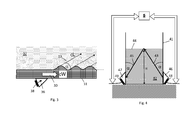
- Figs. 7, 8 and 9 each show a view from the top of a vessel 71, 81, 91 for measuring the speed of sound in a liquid 72, 82, 92 contained in the vessel.
- An acoustic transmitter 77, 87, 97 is mounted below the liquid surface and at the outside of the vessel 71, 81, 91 for transmitting a direct acoustic signal 79, 89, 99 into the liquid to travel inside a first travelling plane towards an acoustic receiver 75, 85, 95.
- the acoustic transmitter and receiver are the same as used for the later liquid level measurement (see Fig. 9 ). However, in the embodiments of Figs.
- Figs. 2 , 5 and 6 only one transducer with integrated transmitter and receiver is needed for the speed of sound calibration. Accordingly, either the transmitter 48 or the receiver 49 or both may be part of a transducer, which transducer may then be used for calibrating the speed of sound in the liquid 42. As a result, the embodiments of Figs. 2 , 5 and 6 would each include at least one additional receiver for performing the speed of sound calibration.
- the assumed first travelling plane in Fig. 7, 8 and 9 is a circular plane lying horizontally and in parallel to the bottom of the vessel 71, 81, 91.
- the acoustic receiver 75, 85, 95 for receiving the direct acoustic signal 79, 89, 99 is also mounted below the liquid surface.
- the acoustic receiver 75, 85, 95 is arranged to receive the direct acoustic signal 79, 89, 99 after it has been reflected by the wall of the vessel 71, 81, 91 which lies - at least to some degree - opposite to the wall where the transmitter 77, 87, 97 and the receiver 75, 85, 95 are mounted at.
- the transmitter 77, 87, 97 is arranged to emit the direct acoustic signal 79, 89, 99 in a direction which is perpendicular to a first reflective surface of the wall of the vessel, so that the direct acoustic signal 29 is reflected back towards its origin and thereby towards the receiver 75, 85, 95.
- the transmitter 77, 87, 97 is further arranged to emit an acoustic wall signal 70, 80, 90 in form of an acoustic wave into the wall of the vessel 71, 81, 91 to travel inside the wall of the vessel along a perimeter of the first travelling plane until it is received by the receiver 75, 85, 95.
- the at least one electronic control and data processing unit 6 is then further arranged to
- the information on the geometric shape of the first travelling plane is also stored in the data memory, which data memory is preferably integrated in the electronic control and data processing unit.
- additional physical effects have to be taken into account, such as delay times occurring in the electronics of transmitter and/or receiver.
- Figs. 7, 8 , 9 show that for measuring the speed of sound in a liquid, two acoustical signals are generated, wherein one (79, 89, 99) travels through the medium to the opposite side of the vessel and is reflected back, the other travels along the solid vessel wall, once around the vessel 71, 81, 91.
- the travel times of the two signals are measured.
- This solution is based on recognition of the fact that the sound velocity in the solid wall varies much less with the wall material and the temperature than in the liquid inside the vessel. Accordingly, the speed of sound in the vessel wall, cW, is assumed to be known.
- the travel time in the vessel wall is used together with the assumed speed of sound cW to determine the vessel perimeter and thus the diameter. With the determined vessel diameter, the speed of sound in the liquid can be calculated out of the travel time in the medium.
- the direct signal (79, 89, 99) is sent horizontally through the medium to the opposite side of the wall, where it is reflected back and received again at the sender.
- a second signal (70, 80, 90) is generated as plate wave in the wall and travels through the wall around the circumference of the vessel. The second signal will be also received again at the sender. The travel times of both signals are measured. The time of flight of the direct signal will be used as described above for the speed of sound measurement in the medium (72, 82, 92).
- the second signal is used for determining the perimeter length of the tank from which then the diameter and thus the traveled distance of the direct signal (79, 89, 99) can be determined.
- the length of the perimeter can be determined out of the time of flight of the second signal (20) analogue to equation (1), where again the propagation velocity has to be known, e.g. the speed of sound in the vessel wall.
- the variation for the speed of sound between different metals is much lower than for liquids, especially for the shear wave velocity.
- the variation with the temperature is by a factor of 10 lower compared to liquids.
- the uncertainty in the perimeter measurement is lower than if the second signal (70, 80, 90) had been travelling in a liquid medium.
- only a small selection of materials is commonly used as wall material for process vessels and the used wall material is often known.
- the temperature of the wall is easier to determine than the temperature of the liquid, e.g. it can be measured by surface temperature sensors, and thus also the temperature dependency of the propagation velocity or speed of sound can be further compensated by a known temperature dependency of the wall material. Consequently, the uncertainty in the value of the speed of sound cL in the liquid used for the level measurement is reduced to the uncertainty of the speed of sound of the wall material.
- the embodiment of Fig. 9 differs from the embodiment of Fig. 7 in that the first acoustic signal 99 is not reflected back from the opposite vessel wall, to reduce the travel distance in case of a liquid 92 with a high damping factor.
- the transmitter 97 is arranged to emit the direct acoustic signal 99 in an angular direction which is not perpendicular to a first reflective surface of the wall of the vessel, so that the first acoustic signal 99 travels straight towards the receiver 95. Accordingly, the generated signal (99) for the speed of sound calibration does not need to travel over the full tank diameter/perimeter.
- an additional transducer may be used at a second point of the vessel's perimeter.
- the signal for the sound calibration (99) can be directed towards this second transducer and has to travel only a shorter distance.
- the second signal traveling through the vessel wall, i.e. the acoustic wall signal 90, would also be received by this second transducer and would also have to cover a shorter path only. This would be of advantage in case of high damping in either the liquid 92 or the wall of vessel 91 or both, or in case that an installation part in the vessel 91 would block a path straight through the middle of the vessel 91.
- the embodiment shown in Fig. 8 differs from the embodiment of Fig. 7 in that the direct acoustic signal 89, which is to travel through the liquid 82, is not sent out straight to the receiving side, but under an angle. It is then reflected several times along the vessel wall. With this embodiment, again problems with installations in the middle of the vessel 81 are avoided, i.e. blocking parts in the middle of the tank are no longer of concern.
- the transmitter 87 and the receiver 85 are integrated in the same device and are mounted at the outside of the wall of vessel 81.
- the transmitter 87 is arranged to emit the direct acoustic signal 89 in an angular direction which is not perpendicular to a first reflective surface of the wall of the vessel, so that the first acoustic signal 89 is reflected more than once by the wall of the vessel 81 before it is received by the receiver 85.
- the direct acoustic signal is received by the receiver either directly ( Fig. 9 ) or as a reflection of it ( Figs. 7, 8 ).
- the vessels are all assumed to have a cylindrical shape at least in the area where the measurement of the speed of sound is performed.
- the view is always shown from the top of the vessel. Due to the cylindrical shape at the height of the speed of sound measurements, the walls of the vessels 71, 81, 91 are all shown as circles.
- the solution proposed here is applicable to any other geometric form as long as this form allows for the travel length of the direct acoustic signal to be obtained when knowing the perimeter of the plane across which the direct acoustic signal propagates.
- Figs. 7 to 9 where the transmitter 77, 87, 97 is arranged to emit the acoustic wall signal as a Lamb wave with a symmetric zero-order mode SO and an asymmetric zero-order mode A0.
- the frequency behavior of these different Lamb wave modes is used to take into account as a further vessel parameter the wall thickness, so as to determine the speed of sound in the wall of the vessel with a higher precision.
- the acoustic waves which are emitted by the transmitter 77, 87, 97 which propagate in the vessel wall are called plate or Lamb waves. As explained above, these waves occur in different kinds of modes each having a different speed of sound and a different dependency of the speed of sound on the frequency f that also depends on the thickness d of the wall.
- the sound velocity of the AO mode increases with the frequency up to the value of about 3000 m/s, given above as the shear velocity in an aluminum or steel bulk material. At higher frequencies, the speed of sound of the AO mode remains nearly constant. At higher frequencies, also the difference between the sound velocity of steel and aluminum for the AO mode is comparatively low. It would thus be of advantage to use for the acoustic wall signal 70, 80, 90 a frequency in this higher frequency range.
- the symmetric SO mode also shows for higher frequencies, when the speed of sound decreases, a quite similar behavior for the different materials, resulting in the sound velocity for the different materials to be quite similar in the higher frequency*thickness range. This is another reason why this frequency*thickness range would be interesting to be used for further decreasing the uncertainty in the sound velocity.
- a low frequency can be chosen in case of a measurement with the symmetric SO mode, or a high frequency can be chosen in case of a measurement with the asymmetric AO mode, where the respective frequency is chosen in such a way that for all values of wall thickness which are to be expected the resulting product of frequency and wall thickness would still result in a sound velocity belonging to the respective constant range in sound velocity.
- the wall thickness may be calculated out of it with the thus known frequency.
- Leaky Lamb waves occur in the case of the AO mode at a wide range of frequency*thickness values, when the wall in which the AO mode propagates is next to a liquid.
- the direction of the radiated beam is not perpendicular to the wall but under an angle which depends on the sound velocity of the Lamb wave and the sound velocity in the liquid.
- the Lamb waves in the wall can be dampened depending on the mode and its frequency*thickness value. Therefore, it is of advantage to perform the perimeter/diameter measurement with the acoustic wall signals 70, 80, 90 at an empty tank.
- the perimeter/diameter measurement needs only to be done once after the installation and can then be used for the further measurements of the speed of sound in the liquid and of the liquid level.
Priority Applications (2)
| Application Number | Priority Date | Filing Date | Title |
|---|---|---|---|
| US15/202,185 US10215613B2 (en) | 2015-07-06 | 2016-07-05 | System and method for non-intrusive and continuous level measurement of a liquid |
| CN201610520472.9A CN106338320B (zh) | 2015-07-06 | 2016-07-05 | 用于液体的非侵入性连续液位测量的系统和方法 |
Applications Claiming Priority (1)
| Application Number | Priority Date | Filing Date | Title |
|---|---|---|---|
| EP15002010 | 2015-07-06 |
Publications (2)
| Publication Number | Publication Date |
|---|---|
| EP3115753A1 true EP3115753A1 (de) | 2017-01-11 |
| EP3115753B1 EP3115753B1 (de) | 2022-01-05 |
Family
ID=53524539
Family Applications (1)
| Application Number | Title | Priority Date | Filing Date |
|---|---|---|---|
| EP15195777.6A Active EP3115753B1 (de) | 2015-07-06 | 2015-11-23 | System und verfahren zur nicht-invasiven und kontinuierlichen füllstandsmessung einer flüssigkeit |
Country Status (3)
| Country | Link |
|---|---|
| US (1) | US10215613B2 (de) |
| EP (1) | EP3115753B1 (de) |
| CN (1) | CN106338320B (de) |
Cited By (10)
| Publication number | Priority date | Publication date | Assignee | Title |
|---|---|---|---|---|
| WO2018162340A1 (en) | 2017-03-07 | 2018-09-13 | Abb Schweiz Ag | Apparatus and method for measuring the flow velocity of a fluid in a pipe |
| WO2019009977A1 (en) * | 2017-07-05 | 2019-01-10 | Saudi Arabian Oil Company | SYSTEM AND METHOD FOR ACOUSTICALLY CALIBRATING THE VOLUME OF A CONTAINER |
| DE102017008545A1 (de) * | 2017-09-11 | 2019-03-14 | Audi Ag | Überwachungssystem zum Überwachen einer Waschflüssigkeitsvorrichtung, Kraftfahrzeug mit einem Überwachungssystem und Verfahren zum Überwachen einer Waschflüssigkeitsvorrichtung |
| US10345135B2 (en) * | 2015-07-31 | 2019-07-09 | Obschestvo S Ogranichennoi Otvetstvennostyu “Nauchno-Issledovatelsky Tsentr Tekhnoavtomat” (Ooo “Nits Tekhnoavtomat”) | Method for controlling the liquid level in tanks as per characteristics of lamb waves and device for ultrasonic control of the liquid level in tanks |
| WO2020048977A1 (en) * | 2018-09-06 | 2020-03-12 | Abb Schweiz Ag | Transducer for non-invasive measurement |
| DE102019216039B3 (de) * | 2019-10-17 | 2021-02-04 | Vitesco Technologies Germany Gmbh | Anordnung und Verfahren zum Feststellen eines Mindestfüllstands eines Fluids in einem Fluidbehälter |
| EP3872459A1 (de) * | 2020-02-28 | 2021-09-01 | Plastic Omnium Advanced Innovation And Research | System zur messung eines fluidparameters |
| CN114370836A (zh) * | 2022-01-07 | 2022-04-19 | 安顺学院 | 一种超声波测量铸锭多晶硅生长速率的装置及其使用方法 |
| DE102021211874A1 (de) | 2021-10-21 | 2023-04-27 | Vitesco Technologies GmbH | Verfahren und Vorrichtung zur Detektion einer zu erwartenden Eisbildung innerhalb eines Waschsystems eines Fahrzeugs |
| US11826781B2 (en) | 2019-09-13 | 2023-11-28 | Abb Schweiz Ag | Ultrasonic transducer for non-invasive measurement |
Families Citing this family (31)
| Publication number | Priority date | Publication date | Assignee | Title |
|---|---|---|---|---|
| EP3115755B1 (de) * | 2015-07-06 | 2022-02-16 | ABB Schweiz AG | System und verfahren zur messung einer schallgeschwindigkeit in einer flüssigen oder gasförmigen medium |
| US10480982B2 (en) * | 2017-04-19 | 2019-11-19 | Saudi Arabian Oil Company | Acoustic calibration array for tanks and vessels |
| US20200109949A1 (en) * | 2017-06-30 | 2020-04-09 | Square Robot, Inc. | Method and apparatus for self-contained positioning of a mobile robot inside a tank |
| CN107340033B (zh) * | 2017-07-19 | 2023-05-12 | 中国科学院西北生态环境资源研究院 | 一种基于声波反射的冻土地区热管工质液面检测装置 |
| JP6971677B2 (ja) * | 2017-07-24 | 2021-11-24 | 株式会社駒井ハルテック | 測定装置及び測定方法 |
| JP6893863B2 (ja) * | 2017-12-04 | 2021-06-23 | 新日本無線株式会社 | 超音波センサおよび車両制御システム |
| US10577919B2 (en) * | 2018-02-27 | 2020-03-03 | Stephen Vaughn Judd | Adaptive acoustic pulse shaping for distance measurements |
| WO2019173616A1 (en) * | 2018-03-08 | 2019-09-12 | Berry Metal Company | Systems and methods for determining the temperature and/or level of a molten metal bath in a vessel |
| CN108536920B (zh) * | 2018-03-19 | 2022-05-31 | 上海理工大学 | 一种计算躺滴Lamb波散射系数的方法 |
| CN112638549B (zh) * | 2018-09-06 | 2022-07-12 | Abb瑞士股份有限公司 | 用于非侵入测量的换能器 |
| CN109855703A (zh) * | 2018-12-20 | 2019-06-07 | 北京铂阳顶荣光伏科技有限公司 | 金属源剩余量的检测装置及检测方法、蒸镀设备 |
| EP3712577B1 (de) * | 2019-03-22 | 2023-07-26 | ABB Schweiz AG | Vorrichtung zur ausrüstungsüberwachung |
| BR112021025099A2 (pt) | 2019-05-31 | 2022-04-26 | Perceptive Sensor Tech Llc | Método de ultrassom não-linear e aparato para detecção quantivativa de materiais (líquidos, gás, plasma) |
| US11231311B2 (en) | 2019-05-31 | 2022-01-25 | Perceptive Sensor Technologies Llc | Non-linear ultrasound method and apparatus for quantitative detection of materials |
| CN110186537A (zh) * | 2019-06-21 | 2019-08-30 | 珠海格力智能装备有限公司 | 设备液位的检测方法及液位检测系统 |
| EP3989836A4 (de) * | 2019-06-26 | 2023-10-04 | Perceptive Sensor Technologies, Inc. | Nichtlineares ultraschallverfahren und -gerät zur quantitativen detektion von materialien |
| CN112146729A (zh) * | 2019-06-28 | 2020-12-29 | 北京铂阳顶荣光伏科技有限公司 | 坩埚内原料剩余量的检测装置及检测方法 |
| EP3822613B1 (de) * | 2019-11-13 | 2023-09-06 | ABB Schweiz AG | Messsystem zur bestimmung von flüssigkeitseigenschaften in einem gefäss |
| EP3822631B1 (de) | 2019-11-13 | 2023-06-28 | ABB Schweiz AG | System und verfahren zur messung einer inhomogenität eines mediums mittels ultraschall |
| US11729537B2 (en) | 2020-12-02 | 2023-08-15 | Perceptive Sensor Technologies, Inc. | Variable angle transducer interface block |
| WO2022120257A1 (en) | 2020-12-04 | 2022-06-09 | Perceptive Sensor Technologies, Inc. | Systems and methods for determining floating roof level tilt and characterizing runoff |
| CA3201100A1 (en) * | 2020-12-04 | 2022-06-09 | Lazar Bivolarsky | Multi-bounce acoustic signal material detection |
| US11604294B2 (en) | 2020-12-04 | 2023-03-14 | Perceptive Sensor Technologies, Inc. | Determining layer characteristics in multi-layered environments |
| WO2022120259A1 (en) | 2020-12-04 | 2022-06-09 | Perceptive Sensor Technologies, Inc. | Apparatus, system, and method for the detection of objects and activity within a container |
| US11788904B2 (en) | 2020-12-04 | 2023-10-17 | Perceptive Sensor Technologies, Inc. | Acoustic temperature measurement in layered environments |
| US11536696B2 (en) | 2020-12-04 | 2022-12-27 | Perceptive Sensor Technologies, Inc. | In-wall multi-bounce material property detection and acoustic signal amplification |
| CN116917729A (zh) | 2020-12-04 | 2023-10-20 | 感知传感器技术股份有限公司 | 多路径声学信号在材料检测方面的改进 |
| CN116829915A (zh) | 2020-12-04 | 2023-09-29 | 感知传感器技术股份有限公司 | 在分层环境中的声学温度测量 |
| WO2022147234A1 (en) | 2020-12-30 | 2022-07-07 | Perceptive Sensor Technologies, Inc. | Evaluation of fluid quality with signals |
| WO2023154514A1 (en) | 2022-02-11 | 2023-08-17 | Perceptive Sensor Technologies, Inc. | Acoustic signal detection of material composition in static and dynamic conditions |
| WO2024091308A1 (en) | 2022-07-19 | 2024-05-02 | Perceptive Sensor Technologies, Inc. | Acoustic signal material identification with nanotube couplant |
Citations (10)
| Publication number | Priority date | Publication date | Assignee | Title |
|---|---|---|---|---|
| DE68903015T2 (de) | 1988-03-08 | 1993-05-06 | Materiel & Auxiliaire | Fluessigkeitsniveauschalter, basierend auf elastischen lamb-wellen zur detektion der anwesenheit einer fluessigkeit. |
| US5251487A (en) * | 1989-03-29 | 1993-10-12 | Martin Marietta Corporation | Apparatus for acoustically coupling an ultrasonic transducer with a body |
| RU2112221C1 (ru) | 1996-07-23 | 1998-05-27 | Акционерное общество "Союзцветметавтоматика" | Способ ультразвукового контроля уровня жидких сред в резервуарах |
| US6234023B1 (en) * | 1995-11-09 | 2001-05-22 | M & A Packaging Services Limited | Ultrasonic monitoring technique for containers and apparatus to carry it out |
| US20050072226A1 (en) * | 2003-09-23 | 2005-04-07 | Pappas Richard A. | Ultrasonic fill level device and method |
| JP2006322825A (ja) | 2005-05-19 | 2006-11-30 | Japan Atomic Energy Agency | 液位測定方法 |
| WO2010034713A2 (en) * | 2008-09-26 | 2010-04-01 | Hochschule Für Angewandte Wissenschaften Fachhochschule Coburg | Method and device for determining characteristics of a medium |
| US7694560B1 (en) | 2007-06-07 | 2010-04-13 | Cosense, Inc. | Non-invasive bottom up continuous liquid level transmitter |
| US20100242593A1 (en) | 2009-03-25 | 2010-09-30 | Lagergren Peter J | Ultrasonic liquid level monitoring system |
| US20140137662A1 (en) * | 2011-03-31 | 2014-05-22 | Rosen Swiss Ag | Acoustic flow rate meter |
Family Cites Families (3)
| Publication number | Priority date | Publication date | Assignee | Title |
|---|---|---|---|---|
| GB8828282D0 (en) * | 1988-12-03 | 1989-01-05 | Sensotect Ltd | Fluid level monitor |
| DE19900832A1 (de) | 1999-01-12 | 2000-07-27 | Sws Werkstoffpruefung Hartmut | Füllstandsermittlung mit Ultraschall |
| EP1059516A1 (de) * | 1999-06-07 | 2000-12-13 | Endress + Hauser GmbH + Co. | Verfahren und Vorrichtung zur Füllstandsmessung an Behältern |
-
2015
- 2015-11-23 EP EP15195777.6A patent/EP3115753B1/de active Active
-
2016
- 2016-07-05 CN CN201610520472.9A patent/CN106338320B/zh active Active
- 2016-07-05 US US15/202,185 patent/US10215613B2/en active Active
Patent Citations (11)
| Publication number | Priority date | Publication date | Assignee | Title |
|---|---|---|---|---|
| DE68903015T2 (de) | 1988-03-08 | 1993-05-06 | Materiel & Auxiliaire | Fluessigkeitsniveauschalter, basierend auf elastischen lamb-wellen zur detektion der anwesenheit einer fluessigkeit. |
| US5251487A (en) * | 1989-03-29 | 1993-10-12 | Martin Marietta Corporation | Apparatus for acoustically coupling an ultrasonic transducer with a body |
| US6234023B1 (en) * | 1995-11-09 | 2001-05-22 | M & A Packaging Services Limited | Ultrasonic monitoring technique for containers and apparatus to carry it out |
| RU2112221C1 (ru) | 1996-07-23 | 1998-05-27 | Акционерное общество "Союзцветметавтоматика" | Способ ультразвукового контроля уровня жидких сред в резервуарах |
| US20050072226A1 (en) * | 2003-09-23 | 2005-04-07 | Pappas Richard A. | Ultrasonic fill level device and method |
| US6925870B2 (en) | 2003-09-23 | 2005-08-09 | Battelle Memorial Institute | Ultrasonic fill level device and method |
| JP2006322825A (ja) | 2005-05-19 | 2006-11-30 | Japan Atomic Energy Agency | 液位測定方法 |
| US7694560B1 (en) | 2007-06-07 | 2010-04-13 | Cosense, Inc. | Non-invasive bottom up continuous liquid level transmitter |
| WO2010034713A2 (en) * | 2008-09-26 | 2010-04-01 | Hochschule Für Angewandte Wissenschaften Fachhochschule Coburg | Method and device for determining characteristics of a medium |
| US20100242593A1 (en) | 2009-03-25 | 2010-09-30 | Lagergren Peter J | Ultrasonic liquid level monitoring system |
| US20140137662A1 (en) * | 2011-03-31 | 2014-05-22 | Rosen Swiss Ag | Acoustic flow rate meter |
Non-Patent Citations (1)
| Title |
|---|
| SAKHAROV: "Liquid level sensor using ultrasonic Lamb waves", ULTRASONICS, vol. 41, 2003, pages 319 - 322, XP004427939, DOI: doi:10.1016/S0041-624X(02)00459-6 |
Cited By (16)
| Publication number | Priority date | Publication date | Assignee | Title |
|---|---|---|---|---|
| US10345135B2 (en) * | 2015-07-31 | 2019-07-09 | Obschestvo S Ogranichennoi Otvetstvennostyu “Nauchno-Issledovatelsky Tsentr Tekhnoavtomat” (Ooo “Nits Tekhnoavtomat”) | Method for controlling the liquid level in tanks as per characteristics of lamb waves and device for ultrasonic control of the liquid level in tanks |
| US11215489B2 (en) | 2017-03-07 | 2022-01-04 | Abb Schweiz Ag | Apparatus and method for measuring the flow velocity of a fluid in a pipe |
| WO2018162340A1 (en) | 2017-03-07 | 2018-09-13 | Abb Schweiz Ag | Apparatus and method for measuring the flow velocity of a fluid in a pipe |
| WO2019009977A1 (en) * | 2017-07-05 | 2019-01-10 | Saudi Arabian Oil Company | SYSTEM AND METHOD FOR ACOUSTICALLY CALIBRATING THE VOLUME OF A CONTAINER |
| US10458831B2 (en) | 2017-07-05 | 2019-10-29 | Saudi Arabian Oil Company | System and method for acoustic container volume calibration |
| US10935408B2 (en) | 2017-07-05 | 2021-03-02 | Saudi Arabian Oil Company | System and method for acoustic container volume calibration |
| DE102017008545A1 (de) * | 2017-09-11 | 2019-03-14 | Audi Ag | Überwachungssystem zum Überwachen einer Waschflüssigkeitsvorrichtung, Kraftfahrzeug mit einem Überwachungssystem und Verfahren zum Überwachen einer Waschflüssigkeitsvorrichtung |
| DE102017008545B4 (de) | 2017-09-11 | 2023-05-11 | Audi Ag | Überwachungssystem zum Überwachen einer Waschflüssigkeitsvorrichtung, Kraftfahrzeug mit einem Überwachungssystem und Verfahren zum Überwachen einer Waschflüssigkeitsvorrichtung |
| US11598663B2 (en) | 2018-09-06 | 2023-03-07 | Abb Schweiz Ag | Transducer for non-invasive measurement |
| WO2020048977A1 (en) * | 2018-09-06 | 2020-03-12 | Abb Schweiz Ag | Transducer for non-invasive measurement |
| US11826781B2 (en) | 2019-09-13 | 2023-11-28 | Abb Schweiz Ag | Ultrasonic transducer for non-invasive measurement |
| DE102019216039B3 (de) * | 2019-10-17 | 2021-02-04 | Vitesco Technologies Germany Gmbh | Anordnung und Verfahren zum Feststellen eines Mindestfüllstands eines Fluids in einem Fluidbehälter |
| FR3107764A1 (fr) * | 2020-02-28 | 2021-09-03 | Plastic Omnium Advanced Innovation And Research | Système de mesure d’un paramètre d’un fluide |
| EP3872459A1 (de) * | 2020-02-28 | 2021-09-01 | Plastic Omnium Advanced Innovation And Research | System zur messung eines fluidparameters |
| DE102021211874A1 (de) | 2021-10-21 | 2023-04-27 | Vitesco Technologies GmbH | Verfahren und Vorrichtung zur Detektion einer zu erwartenden Eisbildung innerhalb eines Waschsystems eines Fahrzeugs |
| CN114370836A (zh) * | 2022-01-07 | 2022-04-19 | 安顺学院 | 一种超声波测量铸锭多晶硅生长速率的装置及其使用方法 |
Also Published As
| Publication number | Publication date |
|---|---|
| US10215613B2 (en) | 2019-02-26 |
| US20170010146A1 (en) | 2017-01-12 |
| CN106338320B (zh) | 2020-03-31 |
| CN106338320A (zh) | 2017-01-18 |
| EP3115753B1 (de) | 2022-01-05 |
Similar Documents
| Publication | Publication Date | Title |
|---|---|---|
| EP3115753B1 (de) | System und verfahren zur nicht-invasiven und kontinuierlichen füllstandsmessung einer flüssigkeit | |
| EP3115755B1 (de) | System und verfahren zur messung einer schallgeschwindigkeit in einer flüssigen oder gasförmigen medium | |
| EP3115754B1 (de) | System und verfahren zur nicht-intrusiven und kontinuierlichen füllstandsmessung in einem zylindrischen behälter | |
| US5119676A (en) | Ultrasonic method and apparatus for determining water level in a closed vessel | |
| EP3115779B1 (de) | System und verfahren zur messung einer signalausbreitungsgeschwindigkeit in einem flüssigen oder gasförmigen medium | |
| US6925870B2 (en) | Ultrasonic fill level device and method | |
| US7481106B2 (en) | Non-invasive method for detecting and measuring filling material in vessels | |
| US6053041A (en) | Noninvasive method for determining the liquid level and density inside of a container | |
| US5877997A (en) | Pulse echo distance measurement | |
| CN110199179B (zh) | 用于检测通流参量的超声波流量计和方法 | |
| US8511144B2 (en) | Torsional sensor, method thereof, and system for measurement of fluid parameters | |
| EP3486619A1 (de) | Vorrichtung und verfahren zur detektion von abscheidungsschichten in einer leitung zum transport einer flüssigkeit oder eines weichen mediums und/oder zur pegeldetektion | |
| JP5224912B2 (ja) | 振動監視装置および監視方法 | |
| JP2011038870A (ja) | 超音波流量計およびこれを用いた流速測定方法 | |
| US20200233070A1 (en) | Ultrasonic wave apparatus for measure of distance | |
| Baranov et al. | Ultrasonic Method for Determining the Liquid Level in an Underground Tank | |
| RU30974U1 (ru) | Ультразвуковое устройство для измерения уровня жидкости в резервуарах | |
| JPH0778445B2 (ja) | 超音波界面レベル計 | |
| JP2018025390A (ja) | 液面計測装置および液面計測方法 | |
| JPH02296115A (ja) | 液面高さの測定方法および測定装置 | |
| JPH0778444B2 (ja) | 超音波を利用した検出計 | |
| JP2005214820A (ja) | ドップラー式超音波流速分布計の超音波送受信ユニット |
Legal Events
| Date | Code | Title | Description |
|---|---|---|---|
| PUAI | Public reference made under article 153(3) epc to a published international application that has entered the european phase |
Free format text: ORIGINAL CODE: 0009012 |
|
| STAA | Information on the status of an ep patent application or granted ep patent |
Free format text: STATUS: THE APPLICATION HAS BEEN PUBLISHED |
|
| AK | Designated contracting states |
Kind code of ref document: A1 Designated state(s): AL AT BE BG CH CY CZ DE DK EE ES FI FR GB GR HR HU IE IS IT LI LT LU LV MC MK MT NL NO PL PT RO RS SE SI SK SM TR |
|
| AX | Request for extension of the european patent |
Extension state: BA ME |
|
| STAA | Information on the status of an ep patent application or granted ep patent |
Free format text: STATUS: REQUEST FOR EXAMINATION WAS MADE |
|
| 17P | Request for examination filed |
Effective date: 20170710 |
|
| GRAP | Despatch of communication of intention to grant a patent |
Free format text: ORIGINAL CODE: EPIDOSNIGR1 |
|
| STAA | Information on the status of an ep patent application or granted ep patent |
Free format text: STATUS: GRANT OF PATENT IS INTENDED |
|
| RIC1 | Information provided on ipc code assigned before grant |
Ipc: G01F 23/296 20060101AFI20210625BHEP Ipc: G01S 7/52 20060101ALI20210625BHEP Ipc: G01S 7/539 20060101ALI20210625BHEP Ipc: G01S 15/32 20060101ALI20210625BHEP Ipc: G01S 15/88 20060101ALI20210625BHEP Ipc: G01N 29/024 20060101ALI20210625BHEP Ipc: G01N 29/22 20060101ALI20210625BHEP Ipc: G01S 7/536 20060101ALI20210625BHEP Ipc: G01S 15/00 20200101ALI20210625BHEP Ipc: G01N 29/04 20060101ALN20210625BHEP Ipc: G01B 17/00 20060101ALN20210625BHEP Ipc: G01H 5/00 20060101ALN20210625BHEP |
|
| RIC1 | Information provided on ipc code assigned before grant |
Ipc: G01F 23/296 20060101AFI20210707BHEP Ipc: G01S 7/52 20060101ALI20210707BHEP Ipc: G01S 7/539 20060101ALI20210707BHEP Ipc: G01S 15/32 20060101ALI20210707BHEP Ipc: G01S 15/88 20060101ALI20210707BHEP Ipc: G01N 29/024 20060101ALI20210707BHEP Ipc: G01N 29/22 20060101ALI20210707BHEP Ipc: G01S 7/536 20060101ALI20210707BHEP Ipc: G01S 15/00 20200101ALI20210707BHEP Ipc: G01N 29/04 20060101ALN20210707BHEP Ipc: G01B 17/00 20060101ALN20210707BHEP Ipc: G01H 5/00 20060101ALN20210707BHEP |
|
| INTG | Intention to grant announced |
Effective date: 20210720 |
|
| GRAS | Grant fee paid |
Free format text: ORIGINAL CODE: EPIDOSNIGR3 |
|
| GRAA | (expected) grant |
Free format text: ORIGINAL CODE: 0009210 |
|
| STAA | Information on the status of an ep patent application or granted ep patent |
Free format text: STATUS: THE PATENT HAS BEEN GRANTED |
|
| RAP3 | Party data changed (applicant data changed or rights of an application transferred) |
Owner name: ABB SCHWEIZ AG |
|
| RIN1 | Information on inventor provided before grant (corrected) |
Inventor name: PAPE, DETLEF Inventor name: KAUFMANN, TOBIAS, DR. Inventor name: LENNER, MIKLOS Inventor name: KASSUBEK, FRANK |
|
| AK | Designated contracting states |
Kind code of ref document: B1 Designated state(s): AL AT BE BG CH CY CZ DE DK EE ES FI FR GB GR HR HU IE IS IT LI LT LU LV MC MK MT NL NO PL PT RO RS SE SI SK SM TR |
|
| REG | Reference to a national code |
Ref country code: GB Ref legal event code: FG4D |
|
| REG | Reference to a national code |
Ref country code: CH Ref legal event code: EP |
|
| REG | Reference to a national code |
Ref country code: AT Ref legal event code: REF Ref document number: 1460988 Country of ref document: AT Kind code of ref document: T Effective date: 20220115 |
|
| REG | Reference to a national code |
Ref country code: DE Ref legal event code: R096 Ref document number: 602015076204 Country of ref document: DE |
|
| REG | Reference to a national code |
Ref country code: IE Ref legal event code: FG4D |
|
| REG | Reference to a national code |
Ref country code: LT Ref legal event code: MG9D |
|
| REG | Reference to a national code |
Ref country code: NL Ref legal event code: MP Effective date: 20220105 |
|
| REG | Reference to a national code |
Ref country code: AT Ref legal event code: MK05 Ref document number: 1460988 Country of ref document: AT Kind code of ref document: T Effective date: 20220105 |
|
| PG25 | Lapsed in a contracting state [announced via postgrant information from national office to epo] |
Ref country code: NL Free format text: LAPSE BECAUSE OF FAILURE TO SUBMIT A TRANSLATION OF THE DESCRIPTION OR TO PAY THE FEE WITHIN THE PRESCRIBED TIME-LIMIT Effective date: 20220105 |
|
| PG25 | Lapsed in a contracting state [announced via postgrant information from national office to epo] |
Ref country code: SE Free format text: LAPSE BECAUSE OF FAILURE TO SUBMIT A TRANSLATION OF THE DESCRIPTION OR TO PAY THE FEE WITHIN THE PRESCRIBED TIME-LIMIT Effective date: 20220105 Ref country code: RS Free format text: LAPSE BECAUSE OF FAILURE TO SUBMIT A TRANSLATION OF THE DESCRIPTION OR TO PAY THE FEE WITHIN THE PRESCRIBED TIME-LIMIT Effective date: 20220105 Ref country code: PT Free format text: LAPSE BECAUSE OF FAILURE TO SUBMIT A TRANSLATION OF THE DESCRIPTION OR TO PAY THE FEE WITHIN THE PRESCRIBED TIME-LIMIT Effective date: 20220505 Ref country code: NO Free format text: LAPSE BECAUSE OF FAILURE TO SUBMIT A TRANSLATION OF THE DESCRIPTION OR TO PAY THE FEE WITHIN THE PRESCRIBED TIME-LIMIT Effective date: 20220405 Ref country code: LT Free format text: LAPSE BECAUSE OF FAILURE TO SUBMIT A TRANSLATION OF THE DESCRIPTION OR TO PAY THE FEE WITHIN THE PRESCRIBED TIME-LIMIT Effective date: 20220105 Ref country code: HR Free format text: LAPSE BECAUSE OF FAILURE TO SUBMIT A TRANSLATION OF THE DESCRIPTION OR TO PAY THE FEE WITHIN THE PRESCRIBED TIME-LIMIT Effective date: 20220105 Ref country code: ES Free format text: LAPSE BECAUSE OF FAILURE TO SUBMIT A TRANSLATION OF THE DESCRIPTION OR TO PAY THE FEE WITHIN THE PRESCRIBED TIME-LIMIT Effective date: 20220105 Ref country code: BG Free format text: LAPSE BECAUSE OF FAILURE TO SUBMIT A TRANSLATION OF THE DESCRIPTION OR TO PAY THE FEE WITHIN THE PRESCRIBED TIME-LIMIT Effective date: 20220405 |
|
| PG25 | Lapsed in a contracting state [announced via postgrant information from national office to epo] |
Ref country code: PL Free format text: LAPSE BECAUSE OF FAILURE TO SUBMIT A TRANSLATION OF THE DESCRIPTION OR TO PAY THE FEE WITHIN THE PRESCRIBED TIME-LIMIT Effective date: 20220105 Ref country code: LV Free format text: LAPSE BECAUSE OF FAILURE TO SUBMIT A TRANSLATION OF THE DESCRIPTION OR TO PAY THE FEE WITHIN THE PRESCRIBED TIME-LIMIT Effective date: 20220105 Ref country code: GR Free format text: LAPSE BECAUSE OF FAILURE TO SUBMIT A TRANSLATION OF THE DESCRIPTION OR TO PAY THE FEE WITHIN THE PRESCRIBED TIME-LIMIT Effective date: 20220406 Ref country code: FI Free format text: LAPSE BECAUSE OF FAILURE TO SUBMIT A TRANSLATION OF THE DESCRIPTION OR TO PAY THE FEE WITHIN THE PRESCRIBED TIME-LIMIT Effective date: 20220105 Ref country code: AT Free format text: LAPSE BECAUSE OF FAILURE TO SUBMIT A TRANSLATION OF THE DESCRIPTION OR TO PAY THE FEE WITHIN THE PRESCRIBED TIME-LIMIT Effective date: 20220105 |
|
| PG25 | Lapsed in a contracting state [announced via postgrant information from national office to epo] |
Ref country code: IS Free format text: LAPSE BECAUSE OF FAILURE TO SUBMIT A TRANSLATION OF THE DESCRIPTION OR TO PAY THE FEE WITHIN THE PRESCRIBED TIME-LIMIT Effective date: 20220505 |
|
| REG | Reference to a national code |
Ref country code: DE Ref legal event code: R097 Ref document number: 602015076204 Country of ref document: DE |
|
| PG25 | Lapsed in a contracting state [announced via postgrant information from national office to epo] |
Ref country code: SM Free format text: LAPSE BECAUSE OF FAILURE TO SUBMIT A TRANSLATION OF THE DESCRIPTION OR TO PAY THE FEE WITHIN THE PRESCRIBED TIME-LIMIT Effective date: 20220105 Ref country code: SK Free format text: LAPSE BECAUSE OF FAILURE TO SUBMIT A TRANSLATION OF THE DESCRIPTION OR TO PAY THE FEE WITHIN THE PRESCRIBED TIME-LIMIT Effective date: 20220105 Ref country code: RO Free format text: LAPSE BECAUSE OF FAILURE TO SUBMIT A TRANSLATION OF THE DESCRIPTION OR TO PAY THE FEE WITHIN THE PRESCRIBED TIME-LIMIT Effective date: 20220105 Ref country code: EE Free format text: LAPSE BECAUSE OF FAILURE TO SUBMIT A TRANSLATION OF THE DESCRIPTION OR TO PAY THE FEE WITHIN THE PRESCRIBED TIME-LIMIT Effective date: 20220105 Ref country code: DK Free format text: LAPSE BECAUSE OF FAILURE TO SUBMIT A TRANSLATION OF THE DESCRIPTION OR TO PAY THE FEE WITHIN THE PRESCRIBED TIME-LIMIT Effective date: 20220105 Ref country code: CZ Free format text: LAPSE BECAUSE OF FAILURE TO SUBMIT A TRANSLATION OF THE DESCRIPTION OR TO PAY THE FEE WITHIN THE PRESCRIBED TIME-LIMIT Effective date: 20220105 |
|
| PLBE | No opposition filed within time limit |
Free format text: ORIGINAL CODE: 0009261 |
|
| STAA | Information on the status of an ep patent application or granted ep patent |
Free format text: STATUS: NO OPPOSITION FILED WITHIN TIME LIMIT |
|
| PG25 | Lapsed in a contracting state [announced via postgrant information from national office to epo] |
Ref country code: AL Free format text: LAPSE BECAUSE OF FAILURE TO SUBMIT A TRANSLATION OF THE DESCRIPTION OR TO PAY THE FEE WITHIN THE PRESCRIBED TIME-LIMIT Effective date: 20220105 |
|
| 26N | No opposition filed |
Effective date: 20221006 |
|
| PG25 | Lapsed in a contracting state [announced via postgrant information from national office to epo] |
Ref country code: SI Free format text: LAPSE BECAUSE OF FAILURE TO SUBMIT A TRANSLATION OF THE DESCRIPTION OR TO PAY THE FEE WITHIN THE PRESCRIBED TIME-LIMIT Effective date: 20220105 |
|
| PG25 | Lapsed in a contracting state [announced via postgrant information from national office to epo] |
Ref country code: MC Free format text: LAPSE BECAUSE OF FAILURE TO SUBMIT A TRANSLATION OF THE DESCRIPTION OR TO PAY THE FEE WITHIN THE PRESCRIBED TIME-LIMIT Effective date: 20220105 |
|
| REG | Reference to a national code |
Ref country code: CH Ref legal event code: PL |
|
| REG | Reference to a national code |
Ref country code: BE Ref legal event code: MM Effective date: 20221130 |
|
| PG25 | Lapsed in a contracting state [announced via postgrant information from national office to epo] |
Ref country code: LI Free format text: LAPSE BECAUSE OF NON-PAYMENT OF DUE FEES Effective date: 20221130 Ref country code: IT Free format text: LAPSE BECAUSE OF FAILURE TO SUBMIT A TRANSLATION OF THE DESCRIPTION OR TO PAY THE FEE WITHIN THE PRESCRIBED TIME-LIMIT Effective date: 20220105 Ref country code: CH Free format text: LAPSE BECAUSE OF NON-PAYMENT OF DUE FEES Effective date: 20221130 |
|
| PG25 | Lapsed in a contracting state [announced via postgrant information from national office to epo] |
Ref country code: LU Free format text: LAPSE BECAUSE OF NON-PAYMENT OF DUE FEES Effective date: 20221123 |
|
| PG25 | Lapsed in a contracting state [announced via postgrant information from national office to epo] |
Ref country code: IE Free format text: LAPSE BECAUSE OF NON-PAYMENT OF DUE FEES Effective date: 20221123 |
|
| PG25 | Lapsed in a contracting state [announced via postgrant information from national office to epo] |
Ref country code: FR Free format text: LAPSE BECAUSE OF NON-PAYMENT OF DUE FEES Effective date: 20221130 Ref country code: BE Free format text: LAPSE BECAUSE OF NON-PAYMENT OF DUE FEES Effective date: 20221130 |
|
| PGFP | Annual fee paid to national office [announced via postgrant information from national office to epo] |
Ref country code: GB Payment date: 20231123 Year of fee payment: 9 |
|
| PGFP | Annual fee paid to national office [announced via postgrant information from national office to epo] |
Ref country code: DE Payment date: 20231121 Year of fee payment: 9 |
|
| PG25 | Lapsed in a contracting state [announced via postgrant information from national office to epo] |
Ref country code: HU Free format text: LAPSE BECAUSE OF FAILURE TO SUBMIT A TRANSLATION OF THE DESCRIPTION OR TO PAY THE FEE WITHIN THE PRESCRIBED TIME-LIMIT; INVALID AB INITIO Effective date: 20151123 |
|
| PG25 | Lapsed in a contracting state [announced via postgrant information from national office to epo] |
Ref country code: CY Free format text: LAPSE BECAUSE OF FAILURE TO SUBMIT A TRANSLATION OF THE DESCRIPTION OR TO PAY THE FEE WITHIN THE PRESCRIBED TIME-LIMIT Effective date: 20220105 |