EP3115674A1 - Support de rotation dote d'un profil plat ne necessitant pas d'outil - Google Patents
Support de rotation dote d'un profil plat ne necessitant pas d'outil Download PDFInfo
- Publication number
- EP3115674A1 EP3115674A1 EP16175266.2A EP16175266A EP3115674A1 EP 3115674 A1 EP3115674 A1 EP 3115674A1 EP 16175266 A EP16175266 A EP 16175266A EP 3115674 A1 EP3115674 A1 EP 3115674A1
- Authority
- EP
- European Patent Office
- Prior art keywords
- key
- ring
- receiver
- plate
- mount
- Prior art date
- Legal status (The legal status is an assumption and is not a legal conclusion. Google has not performed a legal analysis and makes no representation as to the accuracy of the status listed.)
- Granted
Links
- 238000000034 method Methods 0.000 description 11
- 230000008569 process Effects 0.000 description 9
- 238000001746 injection moulding Methods 0.000 description 6
- 239000000463 material Substances 0.000 description 6
- 239000002184 metal Substances 0.000 description 6
- 230000008901 benefit Effects 0.000 description 5
- 239000000654 additive Substances 0.000 description 3
- 230000000996 additive effect Effects 0.000 description 3
- 238000005266 casting Methods 0.000 description 3
- 238000005520 cutting process Methods 0.000 description 3
- 238000003754 machining Methods 0.000 description 3
- 238000004519 manufacturing process Methods 0.000 description 3
- 230000009286 beneficial effect Effects 0.000 description 2
- 230000006835 compression Effects 0.000 description 2
- 238000007906 compression Methods 0.000 description 2
- 230000009467 reduction Effects 0.000 description 2
- 238000010146 3D printing Methods 0.000 description 1
- RZVHIXYEVGDQDX-UHFFFAOYSA-N 9,10-anthraquinone Chemical compound C1=CC=C2C(=O)C3=CC=CC=C3C(=O)C2=C1 RZVHIXYEVGDQDX-UHFFFAOYSA-N 0.000 description 1
- 229910000639 Spring steel Inorganic materials 0.000 description 1
- 238000005219 brazing Methods 0.000 description 1
- 238000010276 construction Methods 0.000 description 1
- 238000005516 engineering process Methods 0.000 description 1
- 230000003993 interaction Effects 0.000 description 1
- 238000012986 modification Methods 0.000 description 1
- 230000004048 modification Effects 0.000 description 1
- 238000010079 rubber tapping Methods 0.000 description 1
- 238000007493 shaping process Methods 0.000 description 1
- 238000004088 simulation Methods 0.000 description 1
- 238000004513 sizing Methods 0.000 description 1
- 230000000007 visual effect Effects 0.000 description 1
- 238000003466 welding Methods 0.000 description 1
Images


Classifications
-
- B—PERFORMING OPERATIONS; TRANSPORTING
- B60—VEHICLES IN GENERAL
- B60R—VEHICLES, VEHICLE FITTINGS, OR VEHICLE PARTS, NOT OTHERWISE PROVIDED FOR
- B60R11/00—Arrangements for holding or mounting articles, not otherwise provided for
- B60R11/02—Arrangements for holding or mounting articles, not otherwise provided for for radio sets, television sets, telephones, or the like; Arrangement of controls thereof
- B60R11/0229—Arrangements for holding or mounting articles, not otherwise provided for for radio sets, television sets, telephones, or the like; Arrangement of controls thereof for displays, e.g. cathodic tubes
- B60R11/0235—Arrangements for holding or mounting articles, not otherwise provided for for radio sets, television sets, telephones, or the like; Arrangement of controls thereof for displays, e.g. cathodic tubes of flat type, e.g. LCD
-
- F—MECHANICAL ENGINEERING; LIGHTING; HEATING; WEAPONS; BLASTING
- F16—ENGINEERING ELEMENTS AND UNITS; GENERAL MEASURES FOR PRODUCING AND MAINTAINING EFFECTIVE FUNCTIONING OF MACHINES OR INSTALLATIONS; THERMAL INSULATION IN GENERAL
- F16M—FRAMES, CASINGS OR BEDS OF ENGINES, MACHINES OR APPARATUS, NOT SPECIFIC TO ENGINES, MACHINES OR APPARATUS PROVIDED FOR ELSEWHERE; STANDS; SUPPORTS
- F16M11/00—Stands or trestles as supports for apparatus or articles placed thereon Stands for scientific apparatus such as gravitational force meters
- F16M11/02—Heads
- F16M11/04—Means for attachment of apparatus; Means allowing adjustment of the apparatus relatively to the stand
- F16M11/041—Allowing quick release of the apparatus
-
- B—PERFORMING OPERATIONS; TRANSPORTING
- B64—AIRCRAFT; AVIATION; COSMONAUTICS
- B64D—EQUIPMENT FOR FITTING IN OR TO AIRCRAFT; FLIGHT SUITS; PARACHUTES; ARRANGEMENTS OR MOUNTING OF POWER PLANTS OR PROPULSION TRANSMISSIONS IN AIRCRAFT
- B64D43/00—Arrangements or adaptations of instruments
-
- F—MECHANICAL ENGINEERING; LIGHTING; HEATING; WEAPONS; BLASTING
- F16—ENGINEERING ELEMENTS AND UNITS; GENERAL MEASURES FOR PRODUCING AND MAINTAINING EFFECTIVE FUNCTIONING OF MACHINES OR INSTALLATIONS; THERMAL INSULATION IN GENERAL
- F16M—FRAMES, CASINGS OR BEDS OF ENGINES, MACHINES OR APPARATUS, NOT SPECIFIC TO ENGINES, MACHINES OR APPARATUS PROVIDED FOR ELSEWHERE; STANDS; SUPPORTS
- F16M13/00—Other supports for positioning apparatus or articles; Means for steadying hand-held apparatus or articles
- F16M13/02—Other supports for positioning apparatus or articles; Means for steadying hand-held apparatus or articles for supporting on, or attaching to, an object, e.g. tree, gate, window-frame, cycle
-
- B—PERFORMING OPERATIONS; TRANSPORTING
- B60—VEHICLES IN GENERAL
- B60R—VEHICLES, VEHICLE FITTINGS, OR VEHICLE PARTS, NOT OTHERWISE PROVIDED FOR
- B60R11/00—Arrangements for holding or mounting articles, not otherwise provided for
- B60R2011/0001—Arrangements for holding or mounting articles, not otherwise provided for characterised by position
- B60R2011/0003—Arrangements for holding or mounting articles, not otherwise provided for characterised by position inside the vehicle
-
- B—PERFORMING OPERATIONS; TRANSPORTING
- B60—VEHICLES IN GENERAL
- B60R—VEHICLES, VEHICLE FITTINGS, OR VEHICLE PARTS, NOT OTHERWISE PROVIDED FOR
- B60R11/00—Arrangements for holding or mounting articles, not otherwise provided for
- B60R2011/0042—Arrangements for holding or mounting articles, not otherwise provided for characterised by mounting means
- B60R2011/0049—Arrangements for holding or mounting articles, not otherwise provided for characterised by mounting means for non integrated articles
- B60R2011/0078—Quick-disconnect two-parts mounting means
-
- B—PERFORMING OPERATIONS; TRANSPORTING
- B60—VEHICLES IN GENERAL
- B60R—VEHICLES, VEHICLE FITTINGS, OR VEHICLE PARTS, NOT OTHERWISE PROVIDED FOR
- B60R11/00—Arrangements for holding or mounting articles, not otherwise provided for
- B60R2011/0042—Arrangements for holding or mounting articles, not otherwise provided for characterised by mounting means
- B60R2011/008—Adjustable or movable supports
- B60R2011/0085—Adjustable or movable supports with adjustment by rotation in their operational position
-
- B—PERFORMING OPERATIONS; TRANSPORTING
- B64—AIRCRAFT; AVIATION; COSMONAUTICS
- B64D—EQUIPMENT FOR FITTING IN OR TO AIRCRAFT; FLIGHT SUITS; PARACHUTES; ARRANGEMENTS OR MOUNTING OF POWER PLANTS OR PROPULSION TRANSMISSIONS IN AIRCRAFT
- B64D45/00—Aircraft indicators or protectors not otherwise provided for
- B64D2045/0075—Adaptations for use of electronic flight bags in aircraft; Supports therefor in the cockpit
-
- F—MECHANICAL ENGINEERING; LIGHTING; HEATING; WEAPONS; BLASTING
- F16—ENGINEERING ELEMENTS AND UNITS; GENERAL MEASURES FOR PRODUCING AND MAINTAINING EFFECTIVE FUNCTIONING OF MACHINES OR INSTALLATIONS; THERMAL INSULATION IN GENERAL
- F16B—DEVICES FOR FASTENING OR SECURING CONSTRUCTIONAL ELEMENTS OR MACHINE PARTS TOGETHER, e.g. NAILS, BOLTS, CIRCLIPS, CLAMPS, CLIPS OR WEDGES; JOINTS OR JOINTING
- F16B21/00—Means for preventing relative axial movement of a pin, spigot, shaft or the like and a member surrounding it; Stud-and-socket releasable fastenings
- F16B21/02—Releasable fastening devices locking by rotation
- F16B21/04—Releasable fastening devices locking by rotation with bayonet catch
-
- F—MECHANICAL ENGINEERING; LIGHTING; HEATING; WEAPONS; BLASTING
- F16—ENGINEERING ELEMENTS AND UNITS; GENERAL MEASURES FOR PRODUCING AND MAINTAINING EFFECTIVE FUNCTIONING OF MACHINES OR INSTALLATIONS; THERMAL INSULATION IN GENERAL
- F16M—FRAMES, CASINGS OR BEDS OF ENGINES, MACHINES OR APPARATUS, NOT SPECIFIC TO ENGINES, MACHINES OR APPARATUS PROVIDED FOR ELSEWHERE; STANDS; SUPPORTS
- F16M2200/00—Details of stands or supports
- F16M2200/02—Locking means
Definitions
- Electronic devices such as laptop computers, notebook computers, and tablet computers can be used to run independent programs. These devices can also send and receive data through a network where programs can be run in another environment, such as a cloud. Data input and output to and from a program or cloud, or the visual interface for the program or cloud, can be displayed on the electronic devices.
- Electronic devices having these capabilities have become increasingly versatile and have been adapted for a wide variety of uses from school work to flight control. These devices often include a touch-sensitive display input integrated into the device screens, which accept touch gestures such as tapping, pinching, or sliding. Because of the user interface required to perform touch gestures, many of these electronic devices require mounts that retain the electronic devices in orientations that allow for their touch screen to be accessed.
- a mount in one embodiment, includes a keyed insert and a key receiver.
- the keyed insert includes a key base and a keyed plate mounted to the key base and having one or more key features extending from a periphery of the keyed plate.
- the key receiver accepts the keyed insert and includes a receiver base, a retaining ring, a key set ring, a key entrance ring, and a spring plate.
- the retaining ring is connected to the receiver base.
- the key set ring is disposed between the retaining ring and the receiver base and includes one or more receiving notches and one or more locking notches.
- the one or more receiving notches is configured to receive the one or more key features the one or more locking notch is spaced away from the one or more receiving notch and is configured to lockingly engage the one or more key features.
- the key entrance ring is disposed between the retaining ring and the key set ring, and includes one or more index notch aligned with the one or more receiving notch.
- the spring plate is movable between the key set ring and the receiver base.
- a system for securing a display device within a aircraft cockpit includes a device holder and a mount.
- the device holder has a front surface and a rear surface, and the front surface is configured to receive the display device.
- the mount is connected to the rear surface of the device holder.
- the mount includes a keyed insert and a key receiver.
- the keyed insert includes a key base and a keyed plate mounted to the key base and having one or more key features extending from a periphery of the keyed plate.
- the key receiver accepts the keyed insert and includes a receiver base, a retaining ring, a key set ring, a key entrance ring, and a spring plate.
- the retaining ring is connected to the receiver base.
- the key set ring is disposed between the retaining ring and the receiver base and includes one or more receiving notches and one or more locking notches.
- the one or more receiving notches is configured to receive the one or more key features the one or more locking notch is spaced away from the one or more receiving notch and is configured to lockingly engage the one or more key features.
- the key entrance ring is disposed between the retaining ring and the key set ring, and includes one or more index notch aligned with the one or more receiving notch.
- the spring plate is movable between the key set ring and the receiver base.
- FIG. 1 is a perspective view of mount system 10 that can mount display device 12 within a cockpit of an aircraft, other uses are available, as discussed below.
- Mount system 10 includes arms 14a-14d. Also displayed in FIG. 1 are sides S1, S2, S3, S4, and cockpit surface CS.
- Display device 12 includes screen 16.
- Arms 14a-14d are extensions of mount system 10 disposed around a periphery of mount system 10. Arm 14a is disposed at side S1; arm 14b is disposed at side S2; arm 14c is disposed at side S3; and, arm 14d is disposed at side S4. Arms 14a-14d contact display device at sides S1, S2, S3, and S4, respectively. Arms 14a-14d also contact screen 16 of display device 12.
- Arms 14a-14d are configured to engage and restrain display device 12.
- Arm 14a can be a releasable arm, so that display device 12 can be easily inserted into and removed from mount system 10.
- Mount system 10 can be attached to cockpit surface CS.
- FIG. 2 is a side isometric view of mount system 10 and display device 12. In this view display device 12 is facing down.
- Mount system 10 includes arms 14a-14d (only arms 14a-14c are shown in FIG. 2 ), main support 18, locking assembly 20, and rotation assembly 22.
- Locking assembly 20 includes handle 23.
- Rotation assembly 22 includes rotation bearing 24 and rotation mount 26.
- Rotation bearing 24 includes rotation flange 27.
- FIG. 2 also shows display device 12 and rear surface R.
- Main support 18 is comprised of a rigid material that is substantially planar, except for arms 14a-14d. Arms 14a-14d extend from a periphery of main support 18, and break from main support 18, away from rear surface R and towards display device 12. Arms 14a-14d extend orthogonally from main support 18, and then break again, to partially extend parallel to main support 18 in a separate plane.
- Locking assembly 20 is connected to rear surface R of main support 18 near arm 14a.
- Locking assembly can include a handle, as shown in FIG. 2 .
- rotation assembly 22 Also connected to rear surface R of main support 18 is rotation assembly 22.
- Rotation bearing 24, of rotation assembly 22 connects to main support 18 through fasteners which can pass through holes drilled into main support 18, securing rotation bearing 24 to main support 18.
- Rotation mount 26 is connected to a portion of rotation bearing 24, securing rotation mount 26 to rotation bearing 24.
- Rotation mount 26 can be connected to a surface in addition to rotation bearing 24.
- rotation mount 26 can be attached to a surface within a cockpit of an aircraft, as shown in FIG. 1 .
- rotation bearing 24 is a substantially circular bearing fastened to main support 18.
- Rotation bearing 24 can include an insert (not shown) that is concentrically circular with rotation flange 27, where the insert engages the inside diameter of rotation flange 27. The insert can then rotate within and relative to rotation flange 27 and therefore relative to main support 18.
- display device 12 can be inserted into main support 18. Arm 14a can then be moved to a secure position, so that arms 14a-14d, along with main support 18 secure display device 12, and restrain the movement of display device 12 relative to main support 18 and mount system 10.
- rotation mount 26 can be attached to a surface, for example cockpit surface CS, as shown in FIG. 1 .
- Fasteners such as bolts, screws, rivets, and the like, can secure rotation mount 26 to the surface, and therefore rotation assembly 22, main support 18, mount system 10, and display device 12 to the surface.
- rotation bearing 24 can allow main support 18 to rotate relative to rotation mount 26, thereby enabling the rotation of mounting system 10 and display device 12 relative to rotation mount 26. This enables a user to, for example, rotate display device 12 and main support 18 from portrait to landscape orientation.
- Rotation mount 26 can enable this operation while rotation mount 26 is locked to the surface to which it is mounted, as described in further detail below.
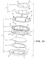
- FIG. 3A is an exploded side isometric view of rotation mount 26.
- FIG. 3B is a side isometric view of rotation mount 26.
- FIGS. 3A and 3B are discussed concurrently.
- Rotation mount 26 includes key insert 30 and keyed receiver 32.
- Key insert 30 includes key base 34 and key plate 36.
- Keyed receiver 32 includes fasteners 38, retaining ring 40, entrance ring 42, key set ring 44, spring plate 46, spring 48, and receiver base 50. Also shown in FIG. 3B is force A.
- Key plate 36 is a substantially circular plate, or cylinder, as is key base 34. In one embodiment, the height or thickness of key plate 36 is substantially smaller than the thickness of key base 34. Key plate 36 and key base 34 are concentric, having substantially the same diameter. In other embodiments, the diameters of key plate 36 and key base 34 bay be different. Further, in some embodiments, key plate 36 and key base 34 can be of other geometric shapes, such as a triangular prism, for example.
- Key plate 36 is attached to key base 34 with fasteners (not shown), such as screws, rivets, and the like.
- key plate 36 and key base 34 can be fastened through another method such as welding or brazing.
- key plate 36 and key base 34 can be comprised of a single piece of material, such as metal, plastic, or another suitable material.
- Retaining ring 40, entrance ring 42, key set ring 44, spring plate 46, and receiver base 50 are substantially circular and concentric, and are comprised of a rigid material, such as metal, plastic, and the like.
- Spring 48 which can be a wave spring comprised of spring steel in one embodiment, is concentric with the components of keyed receiver 32 as well.
- Spring 48 can also be other types of springs, such as one or more coil compression spring, torsion spring, torsion bar, or spring washer.
- Retaining ring 40, entrance ring 42, and key set ring 44 are rings, or hollow cylinders having a small axial height or thickness relative to their diameter. Retaining ring 40, entrance ring 42, and key set ring 44 have substantially similar outer diameters, with varying inner diameters. Receiver base 50 has a larger thickness than, but a similar outer diameter to retaining ring 40, entrance ring 42, and key set ring 44.
- Retaining ring 40, entrance ring 42, and key set ring 44 are fastened to receiver base 50 with fasteners 38, which can be screws, rivets, and the like.
- Spring plate 46 and spring 48 are disposed between retaining ring 40, entrance ring 42, key set ring 44, and receiver base 50.
- Spring plate 46 is free to move between receiver base 50 and key set ring 44, as limited by spring 48, which biases spring plate 46 to contact key set ring 44.
- key plate 36 of key insert 30 can be inserted through retaining ring 40 and into entrance ring 42 when key plate 36 is properly indexed within entrance ring 42. Then, force A can be applied to key plate 36 through key base 34, which transfers to spring plate 46. Thereafter, spring plate 46 can move towards receiver base 50 allowing key plate 36 to enter into key set ring 44, and move beyond key set ring 44. Key plate 36 can then be rotated about its center to lock key plate 36 into key set ring 44. When force A is removed from key insert 30, spring 48 and spring plate 46 will return, preventing key plate 36 from rotating when key plate 36 is locked in key set ring 44. This process can be reversed as described below in FIGS. 4A-4D . The components discussed are described in further detail below.
- Key insert 30 includes key base 34 and key plate 36.
- Keyed receiver 32 includes fasteners 38, retaining ring 40, entrance ring 42, key set ring 44, spring plate 46, spring 48, and receiver base 50.
- Retaining ring 40, entrance ring 42, key set ring 44, and receiver base 50 include holes 58.
- Key base 34 and key plate 36 include bores 54.
- Key plate 36 includes key features 56a-56c.
- Retaining ring 40, entrance ring 42, key set ring 44, and receiver base 50 include holes 58 (shown in FIG. 3A ).
- Entrance ring 42 includes index notches 60a-60c (all shown in FIG. 3A ).
- Key set ring 44 includes receiving notches 62a-62c (all shown in FIG. 3A ), locking notches 64a-64c (all shown in FIG. 3A ), and teeth 66 (all shown in FIG. 3A ).
- Spring plate 46 includes stops 68.
- Receiver base 50 includes flange 70, boss 72, channel 74, and receiver bores 76 (shown only in FIG. 3A ).
- Key plate 36 is attached to key base 34 as described above.
- Key plate 36 is a substantially circular plate.
- Extending from a periphery of key plate 36 are key features 56a-56c.
- key features 56a-56c can be spaced around the perimeter of key plate 36.
- Key features 56a-56c can be equally spaced around the circumference of key plate 36.
- key features 56a-56c can be spaced asymmetrically.
- Each of key features 56a-56c protrude from the periphery of key plate 36 creating a trapezoid with parallel arcs (considering the diameter of key plate 36 as a component).
- key features 56a-56c can have other geometric shapes, such as an isosceles trapezoid.
- Key features 56a-56c can all be of the same size. Additionally, key features 56a-56c can be of varying sizes, and can all be of different sizes. Key features 56a-56c can vary in radial height or thickness, circumferential length, or both. Also, though there are three of key features 56a-56c, fewer or more of key features can be used. For example, two key features can be used. Key features 56a-56c can be subtractively manufactured into key plate 36 through a machining, stamping, or cutting process. Also, key plate 36 can be formed to include bores 54 and key features 56a-56c through a process such as metal injection molding, casting, plastic injection molding, or additive manufacturing (commonly referred to as 3D printing).
- Entrance ring 42 includes index notches 60a-60c (all shown in FIG. 3A ), which are notches or reductions in inner diameter of entrance ring 42.
- Index notches 60a-60c can be subtractively manufactured into entrance ring 42 through a machining, stamping, or cutting process.
- entrance ring 42 can be formed to include holes 38 and index notches 60a-60c through a process such as metal injection molding, casting, plastic injection molding, or additive manufacturing.
- Key set ring 44 includes receiving notches 62a-62c and locking notches 64a-64c (all shown in FIG. 3A ), which are notches or reductions in inner diameter of key set ring 44. Between receiving notches 62a-62c and locking notches 64a-64c are teeth 66 (all shown in FIG. 3A ). Receiving notches 62a-62c and locking notches 64a-64c can be subtractively manufactured into key set ring 44 through a machining, stamping, or cutting process, which simultaneously forms teeth 66. Also, key set ring 44 can be formed to include holes 38, receiving notches 62a-62c, and locking notches 64a-64c through a process such as metal injection molding, casting, plastic injection molding, or additive manufacturing.
- each of index notches 60a-60c (all shown in FIG. 3A ) is a trapezoid with parallel arcs (considering the diameters of key plate 36 as components).
- the profile of each of index notches 60a-60c can be shaped so that it can receive only one of key features 56a-56c.
- index notches 60a-60c can be configured to receive any of key features 56a-56c.
- key features 56a-56c and index notches 60a-60c can be spaced so that index notches 60a-60c will receive key features 56a-56c in only one alignment.
- the profile, size, and shape of receiving notches 62a-62c and locking notches 64a-64c (all shown in FIG.
- index notches 60a-60c and receiving notches 64a-64c account for less than half of the inner circumference of entrance ring 42 and key set ring 44, respectively. This allows for the inclusion of teeth 66 in key set ring 44.
- index notches 60a-60c of entrance ring 42 and receiving notches 62a-62c of key set ring 44 are in alignment when entrance ring 42 and key set ring 44 are connected.
- the alignment of index notches 60a-60c and receiving notches 62a-62c is facilitated by identical or similar geometric shaping and sizing of index notches 60a-60c and receiving notches 62a-62c.
- receiving notches can facilitate alignment by being larger than index notches 60a-60c.
- Spring plate 46 is a substantially circular plate having a diameter that is greater than the inner diameter of key set ring 44, but smaller than the outer diameter of key set ring 44. Stops 68 of spring plate 46 are small extensions of spring plate 46 breaking from spring plate 46 and extending perpendicularly from the surface of spring plate 46. Stops 68 extend away from receiver base 50 and towards retaining ring 40, but do not extend past retaining ring 40.
- Channel 74 (shown in FIG. 3A ) is a channel between boss 72 and flange 70. The height of boss 72 is smaller than the height of flange 70. This provides spring plate 46 with the freedom to move.
- Receiver base 50 has mounting bores 76, for connecting receiver base 50 to another surface, such as rotation bearing 24 (as shown in FIG. 2 ).
- Mounting bores 76 (shown in FIG. 3A ) are located radially between boss 72 and flange 70, in channel 74.
- mounting bores 76 can be counter sunk bores so that fasteners connecting receiver base 50 to another surface do not contact spring 48.
- mounting bores can undercut boss 72, allowing for the diameter of the fastener used to be greater than the width, radially with respect to receiver base 50, of channel 74.
- retaining ring 40, entrance ring 42, key set ring 44, and receiver base 50 are stacked, concentrically, in a non-planar arrangement. Retaining ring 40 is mated to a first surface of entrance ring 42 and a first surface of key set ring 44 is mated to a second surface of entrance ring 42. A second surface of key set ring 44 is mated to flange 70 of receiving base 50.
- holes 58 of retaining ring 40 can align with holes 58 of entrance ring 42, key set ring 44, and receiver base 50.
- Fasteners 38 can pass through holes 58 retaining ring 40, entrance ring 42, and key set ring 44 and fasten to holes 58 in flange 70. Also, holes 58 (shown in FIG. 3A ) of entrance ring 42, key set ring 44, and receiver base 50 can connect to fasteners 38. For example, holes 58 of entrance ring 42, key set ring 44, and receiver base 50 can be tapped to receive fasteners 38, which can be threaded.
- Spring plate 46 and spring 48 are disposed between retaining ring 40, entrance ring 42, key set ring 44, and receiver base 50.
- Spring 48 resides in channel 74 of receiver base 74, protruding, when not compressed, above the surface of boss 72.
- Spring plate 46 is sprung by spring 48, and is free to move between receiver boss 74 of receiver base 50 and the second surface of key set ring 44.
- Spring 48 biases spring plate 46 to contact key set ring 44.
- spring 48 can be an array of compression coil springs circumferentially disposed in channel 74. The operations of these components are described in detail in FIGS. 4A-4D below.
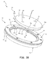
- FIGS. 4A-4D are cross sectionals views of key insert 30 and key receiver 32 of FIGS. 3A and 3B at different stages of a locking process. FIGS. 4A-4D are discussed concurrently.
- Key insert 30 includes key base 34 (removed for better illustration) and key plate 36.
- Keyed receiver 32 includes fasteners 38, retaining ring 40, entrance ring 42, key set ring 44, spring plate 46, spring 48, and receiver base 50.
- Retaining ring 40, entrance ring 42, key set ring 44, and receiver base 50 include holes 58.
- Key plate 36 includes bores 54 and key features 56a-56c (with only key feature 56a shown).
- Retaining ring 40, entrance ring 42, key set ring 44, and receiver base 50 include holes 58.
- Entrance ring 42 includes index notches 60a-60c (with only index notch 60a shown).
- Key set ring 44 includes receiving notches 62a-62c (with only receiving notch 62a shown), locking notches 64a-64c (with only locking notch 60a shown), and teeth 66.
- Spring plate 46 includes stops 68.
- Receiver base 50 includes flange 70, boss 72, and channel 74.
- key plate 36 can be inserted through retaining ring 40 and into entrance ring 42 when key features 56a-56c are indexed so that index notches 60a-60c can receive them.
- key feature 56a can be inserted into indexing notch 60a.
- key plate 36 is substantially level with entrance ring 42, and key features 56a-56c cannot be rotated, because key features 56a-56c will contact indexing notches 60a-60c of entrance ring 42, or stops 68.
- key feature 56a cannot be rotated, because it will contact indexing notch 60a or stop 68.
- spring plate 46 contacts the underside of key set ring 44, as set spring plate 46 is biased to do so by spring 48. In this position, spring plate 46 prevents key feature 56a from moving towards receiver base 50.
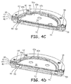
- key features 56a-56c will move past receiving notches 62a-62c, respectively, and can force spring plate 46 to contact boss 72.
- key feature 56a will move past indexing notch 60a and receiving notch 62a, and can force spring plate 46 to contact boss 72, as shown in FIG. 4B .
- key plate 36 can be turned. In some embodiments key plate 36 can be rotated after spring key features 56a-56c have cleared key set ring 44, but before spring plate 46 contacts boss 72.
- key plate 36 The rotation of key plate 36 about its center in a counter-clockwise direction of rotation results in the rotation of key features 56a-56c.
- key feature 62a (and therefore key features 62b and 62c) can only be turned counter-clockwise, as stop 68 prevents key feature 56a from rotating in the clock-wise direction. Stops 68 also prevents spring plate 46 from rotating, by contacting opposite edges of receiving notches 62a and 62b.
- Other embodiments can have one or no stops. Similarly, other embodiments can have more than two of stops 68.
- Key plate 36 and key feature 56a can be rotated counter-clockwise between key set ring 44 and spring plate 46, as shown in FIG. 4C .
- the surface of teeth 66 overlap with the surfaces of key features 56a-56c.
- a first surface (or top surface relative to FIG. 4C ) of key feature 56a contacts (or nearly contacts) tooth 66 as it rotates between tooth 66 and spring plate 46. If force A is removed at this step in the process of rotation, tooth 66 will hold key feature 56a between key set ring 44 and spring plate 46, preventing spring 48 from returning key feature 56a and key plate 36 to level with entrance ring 42.
- Stops 68 prevent key features 56a-56c from over-rotating, or rotating past locking notches 64a-64c. For example, stop 68 prevents key feature 56a from rotating past locking notch 64a. In other words, stops 68 define a range of rotation of key features 56a-56c.
- key features 56a-56c When key features 56a-56c are aligned with locking notches 64a-64c and force A is removed, key features 56a-56c can enter the recess of locking notches 64a-64c. Then, spring plate 46 will return to contacting key set ring 44, and will also contact key features 56a-56c. This prevents key plate 36 from rotating when key plate 36 is locked in key set ring 44. For example, when key feature 56a and locking notch 64a are aligned and force A is removed, or reduced to be smaller than the force applied by spring 48, spring plate 46 will move key plate 36 away from boss 72. Spring plate can continue to travel towards key set ring 44 until it contacts key set ring 44, which prevents spring plate 46 from moving further away from boss 72.
- key feature 56a When spring plate 46 engages key set ring 44, as shown in FIG. 4D , key feature 56a will contact entrance ring 42, and will also be prevented from moving away from boss 72. This is possible when, in some embodiments, key plate 36 is substantially the same thickness as set ring 42. Key feature 56a and therefore key plate 36 will be prevented from rotating in either direction by locking notch 64a and stop 68. This affirmatively locks key feature 56a, key plate 36, and key insert 30 into key receiver 32.
- Key plate 36 can be unlocked from receiver 32 by applying force A on key insert 30, rotating key plate 36 and key features 56a-56c back to alignment with receiving notches 62a-62c, and removing key plate 36 from key receiver 32.
- rotation mount 26 provides the ability to remove mount system 10 from a surface without the use of a tool, increasing the portability of mount system 10 and display device 12.
- crash forces and crash testing forces are typically linear and uni-directional.
- Some mounting systems in the prior art have joints that are separable by these types of crash and crash simulation forces. This disclosure addresses this issue by using rotation mount 26, which locks through rotational movement of insert 30 relative to key receiver 32. Because rotation mount 26 requires rotational forces to lock and unlock, crash testing does not apply a force that would unlock rotation mount 26.
- mount system 10 can be approved for use in an aviation application more easily than the mounts of some prior art.
- retaining ring 40 can provide the benefit of blind alignment. Because rotation mount 26 can be connected to rear surface R of mount system 10, locking insert 30 and receiver 32 may not be visible when inserting insert 30 into receiver 32, for example, in a cockpit, as shown in FIG. 1 .
- Retaining ring 40 allows key features 56a-56c to be blindly aligned in the X-Y plane (where the Z direction is in the direction of force A). That is, retaining ring 40 enables the use of feel to align key plate 36 within retaining ring 40, so that key plate 36 can be easily aligned without seeing the interaction between these components. The remainder of the locking operation can then be performed blindly as well. Key features 56a-56c can be indexed to receiving notches 60a-60c.
- Key plate 36 can move spring plate 46 and key features 56a-56c can be rotated to engage locking notches 64a-64c, respectively.
- the reverse of this process can also be performed blindly, which allows for quick and convenient locking and unlocking of rotation mount 26.
- stops 68 provide the benefit of limiting rotation to useful rotation or useful travel. This saves time when locking insert 30 to receiver 32.
- receiver 32 and insert 30, being comprised of stacked layers of thin material, such as metal, offer a benefit of having a small thickness or profile. This is beneficial to keep a low overall profile of mount system 10. This is especially beneficial when mount system 10 is mounted in a cockpit of an aircraft. Being low profile helps to avoid interference of mount system 10 with other components in the cockpit, such as a tiller.
- key insert 30 can be indexed relative to key receiver 32 quickly. This feature can also provide the benefit of ensuring that mount system 10 is secured to a mounting surface in a desired orientation, such as portrait or landscape, which can also save time.
- a mount includes a keyed insert and a key receiver.
- the keyed insert includes a key base and a keyed plate mounted to the key base and having one or more key features extending from a periphery of the keyed plate.
- the key receiver accepts the keyed insert and includes a receiver base, a retaining ring, a key set ring, a key entrance ring, and a spring plate.
- the retaining ring is connected to the receiver base.
- the key set ring is disposed between the retaining ring and the receiver base and includes one or more receiving notches and one or more locking notches.
- the one or more receiving notches is configured to receive the one or more key features the one or more locking notch is spaced away from the one or more receiving notch and is configured to lockingly engage the one or more key features.
- the key entrance ring is disposed between the retaining ring and the key set ring, and includes one or more index notch aligned with the one or more receiving notch.
- the spring plate is movable between the key set ring and the receiver base.
- the mount of the preceding paragraph can optionally include, additionally and/or alternatively, any one or more of the following features, configurations, and/or additional components.
- the spring plate can be configured to be displaced by the key plate to allow the key feature to rotate amid the key set ring and the spring plate between the one or more receiving notches and the one or more locking notches.
- the spring plate can include stops that define a range of rotation of the one or more key features between the one or more receiving notches and the one or more locking notches.
- a spring can apply a force on the spring plate and the receiver, which can bias the spring plate to contact the key set ring.
- the spring can be a wave spring.
- a spring retainer channel can be between a center and a perimeter of the receiver base.
- a boss can restrict travel of the spring plate in an axial direction within the receiver.
- the key plate can include a plurality of key features
- the key set ring can include a plurality of receiving notches and a plurality of locking notches
- the key entrance ring can include a plurality of index notches.
- the plurality of key features can have different geometric shapes.
- Each index notch of the plurality of index notches can have a geometrical shape configured to receive only one key feature of the plurality of key features.
- the plurality of key features can be disposed along than half of a perimeter of the key plate.
- the key base, the receiving base, the retaining ring, the key set ring, key entrance ring, and spring plate can be substantially circular.
- the key receiver can be include a display device holder that can be connected to the key receiver.
- a system for securing a display device within a aircraft cockpit includes a device holder and a mount.
- the device holder has a front surface and a rear surface, and the front surface is configured to receive the display device.
- the mount is connected to the rear surface of the device holder.
- the mount includes a keyed insert and a key receiver.
- the keyed insert includes a key base and a keyed plate mounted to the key base and having one or more key features extending from a periphery of the keyed plate.
- the key receiver accepts the keyed insert and includes a receiver base, a retaining ring, a key set ring, a key entrance ring, and a spring plate.
- the retaining ring is connected to the receiver base.
- the key set ring is disposed between the retaining ring and the receiver base and includes one or more receiving notches and one or more locking notches.
- the one or more receiving notches is configured to receive the one or more key features the one or more locking notch is spaced away from the one or more receiving notch and is configured to lockingly engage the one or more key features.
- the key entrance ring is disposed between the retaining ring and the key set ring, and includes one or more index notch aligned with the one or more receiving notch.
- the spring plate is movable between the key set ring and the receiver base.
- the system of the preceding paragraph can optionally include, additionally and/or alternatively, any one or more of the following features, configurations, and/or additional components.
- the key receiver can be mounted to the device holder.
- the keyed insert can be mounted to a part of the cockpit.
- the spring plate can be configured to be displaced by the key plate to allow the key feature to rotate amid the key set ring and the spring plate between the receiving notch and the locking notch.
Applications Claiming Priority (1)
| Application Number | Priority Date | Filing Date | Title |
|---|---|---|---|
| US14/744,317 US9604580B2 (en) | 2015-06-19 | 2015-06-19 | Tool-less low profile rotation mount |
Publications (2)
| Publication Number | Publication Date |
|---|---|
| EP3115674A1 true EP3115674A1 (fr) | 2017-01-11 |
| EP3115674B1 EP3115674B1 (fr) | 2018-08-22 |
Family
ID=56413471
Family Applications (1)
| Application Number | Title | Priority Date | Filing Date |
|---|---|---|---|
| EP16175266.2A Active EP3115674B1 (fr) | 2015-06-19 | 2016-06-20 | Support de rotation dote d'un profil plat ne necessitant pas d'outil |
Country Status (3)
| Country | Link |
|---|---|
| US (1) | US9604580B2 (fr) |
| EP (1) | EP3115674B1 (fr) |
| CA (1) | CA2927261C (fr) |
Cited By (2)
| Publication number | Priority date | Publication date | Assignee | Title |
|---|---|---|---|---|
| CN109435851A (zh) * | 2018-10-29 | 2019-03-08 | 崔云兰 | 一种便携式车载抬头显示装置及其工作方法 |
| WO2019053275A1 (fr) * | 2017-09-15 | 2019-03-21 | Nolii Limited | Mécanisme de verrouillage |
Families Citing this family (8)
| Publication number | Priority date | Publication date | Assignee | Title |
|---|---|---|---|---|
| DE202016005501U1 (de) * | 2015-09-11 | 2016-11-21 | Hyster-Yale Group, Inc. | Zubehörarm für einen Gabelstapler |
| US9919659B2 (en) * | 2015-12-22 | 2018-03-20 | Fca Us Llc | Adjustable mobile-device holder |
| FR3106813A1 (fr) * | 2020-02-03 | 2021-08-06 | Airbus Operations | Ensemble pour un aeronef comportant un tableau de bord et un systeme de support pour une tablette tactile |
| US11001206B1 (en) * | 2020-02-28 | 2021-05-11 | National Creative Enterprises, Inc. | Mounting assembly |
| US11007951B1 (en) * | 2020-02-28 | 2021-05-18 | National Creative Enterprises, Inc. | Mounting assembly |
| US11840179B2 (en) * | 2021-08-16 | 2023-12-12 | William J. Lucas | Camera/lens mounting platform for vehicle |
| US20230392745A1 (en) * | 2022-06-01 | 2023-12-07 | Jinyan Duan | Turner apparatus |
| US11951912B1 (en) * | 2022-08-01 | 2024-04-09 | Catchjak Inc. | Door mount device holder |
Citations (4)
| Publication number | Priority date | Publication date | Assignee | Title |
|---|---|---|---|---|
| US6292142B1 (en) * | 1999-05-24 | 2001-09-18 | Raytheon Company | Locking assembly |
| US20140262847A1 (en) * | 2013-03-15 | 2014-09-18 | The Joy Factory, Inc. | Case structures for portable electronic devices |
| EP2803585A1 (fr) * | 2013-05-14 | 2014-11-19 | Rosemount Aerospace Inc. | Support rotatif d'affichage électronique |
| EP2808593A2 (fr) * | 2013-05-21 | 2014-12-03 | Rosemount Aerospace Inc. | Adaptateur d'affichage électronique rotatif |
Family Cites Families (21)
| Publication number | Priority date | Publication date | Assignee | Title |
|---|---|---|---|---|
| JPH0623821B2 (ja) | 1983-09-02 | 1994-03-30 | ミノルタカメラ株式会社 | バヨネットマウント装置とこの装置を用いる光学機器 |
| AU566846B2 (en) * | 1983-11-11 | 1987-10-29 | Suntory Limited | Rotating mechanism attachable to bottom of container |
| US4969623A (en) * | 1989-03-01 | 1990-11-13 | Bernier Rene A | Flight documents organizer |
| US4948083A (en) * | 1989-04-17 | 1990-08-14 | Penn Fishing And Tackle Mfg. Co. | Swivel base mount for downrigger |
| US5451022A (en) * | 1994-02-22 | 1995-09-19 | Wayne State University | Mounting bracket for a sun visor |
| DE19833157A1 (de) * | 1998-07-23 | 2000-01-27 | Bosch Gmbh Robert | Vorrichtung zur Befestigung und Ausrichtung eines Gerätes an einem Halterahmen |
| US6933861B2 (en) * | 2002-11-29 | 2005-08-23 | Alfadata Computer Corp. | Key-operating device for a hand-held video game apparatus |
| TW588818U (en) * | 2003-03-11 | 2004-05-21 | Top Victory Electronics Taiwan | Rotatable supporting station |
| US7314203B2 (en) * | 2004-12-15 | 2008-01-01 | Chi Yau Yue | Base for vanity mirror or other small object with enhanced stability and rotational ability |
| DE102005046806B3 (de) * | 2005-09-30 | 2007-04-19 | Keiper Gmbh & Co.Kg | Beschlag für einen Fahrzeugsitz |
| US8020816B2 (en) * | 2006-01-30 | 2011-09-20 | Laicor Fixtures, Inc. | Information transfer device support stand |
| JP4974592B2 (ja) | 2006-06-23 | 2012-07-11 | ペンタックスリコーイメージング株式会社 | レンズ補助部品の取付装置 |
| JP4148972B2 (ja) * | 2006-07-10 | 2008-09-10 | 三菱電機株式会社 | 回転台及び表示装置 |
| US7866894B2 (en) * | 2006-09-25 | 2011-01-11 | Baldor Electric Company | Hydraulically positioned shaft bearing attachment system and method |
| US20100050706A1 (en) * | 2008-09-03 | 2010-03-04 | Lucasey Manufacturing Company | Releasable security mount |
| US20100288902A1 (en) * | 2009-05-14 | 2010-11-18 | Jan-Ban Liu | Rotatable support capable of adjusting a tilting angle by handling a linking rod thereof |
| US20110101058A1 (en) | 2009-05-28 | 2011-05-05 | Tom Heckman | Pivot mount assembly |
| CN101930693A (zh) * | 2009-06-18 | 2010-12-29 | 鸿富锦精密工业(深圳)有限公司 | 铭牌安装装置 |
| PL2466159T3 (pl) * | 2010-12-15 | 2014-01-31 | Agustawestland Spa | Zespół mocujący |
| US9280037B2 (en) | 2012-05-03 | 2016-03-08 | Serview, Inc. | Machine vision camera mount with rotational adjustment |
| KR102131392B1 (ko) * | 2014-01-03 | 2020-07-08 | 삼성전자주식회사 | 보호 커버 |
-
2015
- 2015-06-19 US US14/744,317 patent/US9604580B2/en active Active
-
2016
- 2016-04-14 CA CA2927261A patent/CA2927261C/fr active Active
- 2016-06-20 EP EP16175266.2A patent/EP3115674B1/fr active Active
Patent Citations (4)
| Publication number | Priority date | Publication date | Assignee | Title |
|---|---|---|---|---|
| US6292142B1 (en) * | 1999-05-24 | 2001-09-18 | Raytheon Company | Locking assembly |
| US20140262847A1 (en) * | 2013-03-15 | 2014-09-18 | The Joy Factory, Inc. | Case structures for portable electronic devices |
| EP2803585A1 (fr) * | 2013-05-14 | 2014-11-19 | Rosemount Aerospace Inc. | Support rotatif d'affichage électronique |
| EP2808593A2 (fr) * | 2013-05-21 | 2014-12-03 | Rosemount Aerospace Inc. | Adaptateur d'affichage électronique rotatif |
Cited By (3)
| Publication number | Priority date | Publication date | Assignee | Title |
|---|---|---|---|---|
| WO2019053275A1 (fr) * | 2017-09-15 | 2019-03-21 | Nolii Limited | Mécanisme de verrouillage |
| GB2571501B (en) * | 2017-09-15 | 2022-12-21 | Nolii Ltd | Locking mechanism |
| CN109435851A (zh) * | 2018-10-29 | 2019-03-08 | 崔云兰 | 一种便携式车载抬头显示装置及其工作方法 |
Also Published As
| Publication number | Publication date |
|---|---|
| EP3115674B1 (fr) | 2018-08-22 |
| CA2927261C (fr) | 2022-12-13 |
| CA2927261A1 (fr) | 2016-12-19 |
| US20160368431A1 (en) | 2016-12-22 |
| US9604580B2 (en) | 2017-03-28 |
Similar Documents
| Publication | Publication Date | Title |
|---|---|---|
| EP3115674B1 (fr) | Support de rotation dote d'un profil plat ne necessitant pas d'outil | |
| US9587782B2 (en) | Display device holder | |
| US9170613B2 (en) | Connecting assembly and electronic device having the same | |
| US9696754B2 (en) | Hinge having multiple degrees of freedom | |
| EP3106737B1 (fr) | Montage de position multiple avec mécanisme de retenue | |
| US10046862B2 (en) | Electronic display mounting apparatus | |
| US9298271B2 (en) | Mounting device and electronic apparatus | |
| US9338902B2 (en) | Electronic device with support | |
| CN104279415B (zh) | 旋转式电子显示适配器 | |
| US20120176743A1 (en) | Hard disk module and hard disk securing apparatus thereof | |
| US20120217856A1 (en) | Electronic device enclosure for receiving storage device | |
| US9110638B2 (en) | Pointing device | |
| US8100259B2 (en) | Carrier apparatus for fastener | |
| US8625304B2 (en) | Supporting mechanism for electronic device | |
| US8918961B2 (en) | Electronic device with hinge structure | |
| US8870172B2 (en) | Test support apparatus | |
| US20130161274A1 (en) | Mounting apparatus for mounting tray for securing expansion card | |
| US20160292463A1 (en) | Computing device security lock | |
| US20140104779A1 (en) | Mounting apparatus for data storage device | |
| CN107505994B (zh) | 一种扩展卡的固定装置及机箱 | |
| US8068192B2 (en) | LCD assembly | |
| US20130014910A1 (en) | Heat dissipating apparatus for electronic device | |
| US8737056B2 (en) | Mounting apparatus and vibration dampening structure for electronic device | |
| JP5584903B2 (ja) | 支持部材及び支持システム | |
| EP3366521A1 (fr) | Système de montage d'objet dans un véhicule |
Legal Events
| Date | Code | Title | Description |
|---|---|---|---|
| PUAI | Public reference made under article 153(3) epc to a published international application that has entered the european phase |
Free format text: ORIGINAL CODE: 0009012 |
|
| STAA | Information on the status of an ep patent application or granted ep patent |
Free format text: STATUS: THE APPLICATION HAS BEEN PUBLISHED |
|
| AK | Designated contracting states |
Kind code of ref document: A1 Designated state(s): AL AT BE BG CH CY CZ DE DK EE ES FI FR GB GR HR HU IE IS IT LI LT LU LV MC MK MT NL NO PL PT RO RS SE SI SK SM TR |
|
| AX | Request for extension of the european patent |
Extension state: BA ME |
|
| STAA | Information on the status of an ep patent application or granted ep patent |
Free format text: STATUS: REQUEST FOR EXAMINATION WAS MADE |
|
| 17P | Request for examination filed |
Effective date: 20170707 |
|
| RBV | Designated contracting states (corrected) |
Designated state(s): AL AT BE BG CH CY CZ DE DK EE ES FI FR GB GR HR HU IE IS IT LI LT LU LV MC MK MT NL NO PL PT RO RS SE SI SK SM TR |
|
| GRAP | Despatch of communication of intention to grant a patent |
Free format text: ORIGINAL CODE: EPIDOSNIGR1 |
|
| STAA | Information on the status of an ep patent application or granted ep patent |
Free format text: STATUS: GRANT OF PATENT IS INTENDED |
|
| INTG | Intention to grant announced |
Effective date: 20180223 |
|
| GRAS | Grant fee paid |
Free format text: ORIGINAL CODE: EPIDOSNIGR3 |
|
| GRAA | (expected) grant |
Free format text: ORIGINAL CODE: 0009210 |
|
| STAA | Information on the status of an ep patent application or granted ep patent |
Free format text: STATUS: THE PATENT HAS BEEN GRANTED |
|
| RIN1 | Information on inventor provided before grant (corrected) |
Inventor name: BOER, JONATHAN Inventor name: LOVAASEN, ERIC Inventor name: FREEMAN, KENNETH |
|
| AK | Designated contracting states |
Kind code of ref document: B1 Designated state(s): AL AT BE BG CH CY CZ DE DK EE ES FI FR GB GR HR HU IE IS IT LI LT LU LV MC MK MT NL NO PL PT RO RS SE SI SK SM TR |
|
| REG | Reference to a national code |
Ref country code: GB Ref legal event code: FG4D |
|
| REG | Reference to a national code |
Ref country code: CH Ref legal event code: EP |
|
| REG | Reference to a national code |
Ref country code: AT Ref legal event code: REF Ref document number: 1032939 Country of ref document: AT Kind code of ref document: T Effective date: 20180915 |
|
| REG | Reference to a national code |
Ref country code: IE Ref legal event code: FG4D |
|
| REG | Reference to a national code |
Ref country code: DE Ref legal event code: R096 Ref document number: 602016004924 Country of ref document: DE |
|
| REG | Reference to a national code |
Ref country code: NL Ref legal event code: MP Effective date: 20180822 |
|
| REG | Reference to a national code |
Ref country code: LT Ref legal event code: MG4D |
|
| PG25 | Lapsed in a contracting state [announced via postgrant information from national office to epo] |
Ref country code: FI Free format text: LAPSE BECAUSE OF FAILURE TO SUBMIT A TRANSLATION OF THE DESCRIPTION OR TO PAY THE FEE WITHIN THE PRESCRIBED TIME-LIMIT Effective date: 20180822 Ref country code: NL Free format text: LAPSE BECAUSE OF FAILURE TO SUBMIT A TRANSLATION OF THE DESCRIPTION OR TO PAY THE FEE WITHIN THE PRESCRIBED TIME-LIMIT Effective date: 20180822 Ref country code: LT Free format text: LAPSE BECAUSE OF FAILURE TO SUBMIT A TRANSLATION OF THE DESCRIPTION OR TO PAY THE FEE WITHIN THE PRESCRIBED TIME-LIMIT Effective date: 20180822 Ref country code: SE Free format text: LAPSE BECAUSE OF FAILURE TO SUBMIT A TRANSLATION OF THE DESCRIPTION OR TO PAY THE FEE WITHIN THE PRESCRIBED TIME-LIMIT Effective date: 20180822 Ref country code: BG Free format text: LAPSE BECAUSE OF FAILURE TO SUBMIT A TRANSLATION OF THE DESCRIPTION OR TO PAY THE FEE WITHIN THE PRESCRIBED TIME-LIMIT Effective date: 20181122 Ref country code: RS Free format text: LAPSE BECAUSE OF FAILURE TO SUBMIT A TRANSLATION OF THE DESCRIPTION OR TO PAY THE FEE WITHIN THE PRESCRIBED TIME-LIMIT Effective date: 20180822 Ref country code: GR Free format text: LAPSE BECAUSE OF FAILURE TO SUBMIT A TRANSLATION OF THE DESCRIPTION OR TO PAY THE FEE WITHIN THE PRESCRIBED TIME-LIMIT Effective date: 20181123 Ref country code: IS Free format text: LAPSE BECAUSE OF FAILURE TO SUBMIT A TRANSLATION OF THE DESCRIPTION OR TO PAY THE FEE WITHIN THE PRESCRIBED TIME-LIMIT Effective date: 20181222 Ref country code: NO Free format text: LAPSE BECAUSE OF FAILURE TO SUBMIT A TRANSLATION OF THE DESCRIPTION OR TO PAY THE FEE WITHIN THE PRESCRIBED TIME-LIMIT Effective date: 20181122 |
|
| REG | Reference to a national code |
Ref country code: AT Ref legal event code: MK05 Ref document number: 1032939 Country of ref document: AT Kind code of ref document: T Effective date: 20180822 |
|
| PG25 | Lapsed in a contracting state [announced via postgrant information from national office to epo] |
Ref country code: HR Free format text: LAPSE BECAUSE OF FAILURE TO SUBMIT A TRANSLATION OF THE DESCRIPTION OR TO PAY THE FEE WITHIN THE PRESCRIBED TIME-LIMIT Effective date: 20180822 Ref country code: AL Free format text: LAPSE BECAUSE OF FAILURE TO SUBMIT A TRANSLATION OF THE DESCRIPTION OR TO PAY THE FEE WITHIN THE PRESCRIBED TIME-LIMIT Effective date: 20180822 Ref country code: LV Free format text: LAPSE BECAUSE OF FAILURE TO SUBMIT A TRANSLATION OF THE DESCRIPTION OR TO PAY THE FEE WITHIN THE PRESCRIBED TIME-LIMIT Effective date: 20180822 |
|
| PG25 | Lapsed in a contracting state [announced via postgrant information from national office to epo] |
Ref country code: CZ Free format text: LAPSE BECAUSE OF FAILURE TO SUBMIT A TRANSLATION OF THE DESCRIPTION OR TO PAY THE FEE WITHIN THE PRESCRIBED TIME-LIMIT Effective date: 20180822 Ref country code: ES Free format text: LAPSE BECAUSE OF FAILURE TO SUBMIT A TRANSLATION OF THE DESCRIPTION OR TO PAY THE FEE WITHIN THE PRESCRIBED TIME-LIMIT Effective date: 20180822 Ref country code: RO Free format text: LAPSE BECAUSE OF FAILURE TO SUBMIT A TRANSLATION OF THE DESCRIPTION OR TO PAY THE FEE WITHIN THE PRESCRIBED TIME-LIMIT Effective date: 20180822 Ref country code: IT Free format text: LAPSE BECAUSE OF FAILURE TO SUBMIT A TRANSLATION OF THE DESCRIPTION OR TO PAY THE FEE WITHIN THE PRESCRIBED TIME-LIMIT Effective date: 20180822 Ref country code: AT Free format text: LAPSE BECAUSE OF FAILURE TO SUBMIT A TRANSLATION OF THE DESCRIPTION OR TO PAY THE FEE WITHIN THE PRESCRIBED TIME-LIMIT Effective date: 20180822 Ref country code: EE Free format text: LAPSE BECAUSE OF FAILURE TO SUBMIT A TRANSLATION OF THE DESCRIPTION OR TO PAY THE FEE WITHIN THE PRESCRIBED TIME-LIMIT Effective date: 20180822 Ref country code: PL Free format text: LAPSE BECAUSE OF FAILURE TO SUBMIT A TRANSLATION OF THE DESCRIPTION OR TO PAY THE FEE WITHIN THE PRESCRIBED TIME-LIMIT Effective date: 20180822 |
|
| REG | Reference to a national code |
Ref country code: DE Ref legal event code: R097 Ref document number: 602016004924 Country of ref document: DE |
|
| PG25 | Lapsed in a contracting state [announced via postgrant information from national office to epo] |
Ref country code: SK Free format text: LAPSE BECAUSE OF FAILURE TO SUBMIT A TRANSLATION OF THE DESCRIPTION OR TO PAY THE FEE WITHIN THE PRESCRIBED TIME-LIMIT Effective date: 20180822 Ref country code: DK Free format text: LAPSE BECAUSE OF FAILURE TO SUBMIT A TRANSLATION OF THE DESCRIPTION OR TO PAY THE FEE WITHIN THE PRESCRIBED TIME-LIMIT Effective date: 20180822 Ref country code: SM Free format text: LAPSE BECAUSE OF FAILURE TO SUBMIT A TRANSLATION OF THE DESCRIPTION OR TO PAY THE FEE WITHIN THE PRESCRIBED TIME-LIMIT Effective date: 20180822 |
|
| PLBE | No opposition filed within time limit |
Free format text: ORIGINAL CODE: 0009261 |
|
| STAA | Information on the status of an ep patent application or granted ep patent |
Free format text: STATUS: NO OPPOSITION FILED WITHIN TIME LIMIT |
|
| 26N | No opposition filed |
Effective date: 20190523 |
|
| PG25 | Lapsed in a contracting state [announced via postgrant information from national office to epo] |
Ref country code: SI Free format text: LAPSE BECAUSE OF FAILURE TO SUBMIT A TRANSLATION OF THE DESCRIPTION OR TO PAY THE FEE WITHIN THE PRESCRIBED TIME-LIMIT Effective date: 20180822 |
|
| PG25 | Lapsed in a contracting state [announced via postgrant information from national office to epo] |
Ref country code: MC Free format text: LAPSE BECAUSE OF FAILURE TO SUBMIT A TRANSLATION OF THE DESCRIPTION OR TO PAY THE FEE WITHIN THE PRESCRIBED TIME-LIMIT Effective date: 20180822 |
|
| REG | Reference to a national code |
Ref country code: CH Ref legal event code: PL |
|
| REG | Reference to a national code |
Ref country code: BE Ref legal event code: MM Effective date: 20190630 |
|
| PG25 | Lapsed in a contracting state [announced via postgrant information from national office to epo] |
Ref country code: TR Free format text: LAPSE BECAUSE OF FAILURE TO SUBMIT A TRANSLATION OF THE DESCRIPTION OR TO PAY THE FEE WITHIN THE PRESCRIBED TIME-LIMIT Effective date: 20180822 |
|
| PG25 | Lapsed in a contracting state [announced via postgrant information from national office to epo] |
Ref country code: IE Free format text: LAPSE BECAUSE OF NON-PAYMENT OF DUE FEES Effective date: 20190620 |
|
| PG25 | Lapsed in a contracting state [announced via postgrant information from national office to epo] |
Ref country code: BE Free format text: LAPSE BECAUSE OF NON-PAYMENT OF DUE FEES Effective date: 20190630 Ref country code: LU Free format text: LAPSE BECAUSE OF NON-PAYMENT OF DUE FEES Effective date: 20190620 Ref country code: LI Free format text: LAPSE BECAUSE OF NON-PAYMENT OF DUE FEES Effective date: 20190630 Ref country code: CH Free format text: LAPSE BECAUSE OF NON-PAYMENT OF DUE FEES Effective date: 20190630 |
|
| PG25 | Lapsed in a contracting state [announced via postgrant information from national office to epo] |
Ref country code: PT Free format text: LAPSE BECAUSE OF FAILURE TO SUBMIT A TRANSLATION OF THE DESCRIPTION OR TO PAY THE FEE WITHIN THE PRESCRIBED TIME-LIMIT Effective date: 20181222 |
|
| PG25 | Lapsed in a contracting state [announced via postgrant information from national office to epo] |
Ref country code: CY Free format text: LAPSE BECAUSE OF FAILURE TO SUBMIT A TRANSLATION OF THE DESCRIPTION OR TO PAY THE FEE WITHIN THE PRESCRIBED TIME-LIMIT Effective date: 20180822 |
|
| PG25 | Lapsed in a contracting state [announced via postgrant information from national office to epo] |
Ref country code: HU Free format text: LAPSE BECAUSE OF FAILURE TO SUBMIT A TRANSLATION OF THE DESCRIPTION OR TO PAY THE FEE WITHIN THE PRESCRIBED TIME-LIMIT; INVALID AB INITIO Effective date: 20160620 Ref country code: MT Free format text: LAPSE BECAUSE OF FAILURE TO SUBMIT A TRANSLATION OF THE DESCRIPTION OR TO PAY THE FEE WITHIN THE PRESCRIBED TIME-LIMIT Effective date: 20180822 |
|
| PG25 | Lapsed in a contracting state [announced via postgrant information from national office to epo] |
Ref country code: MK Free format text: LAPSE BECAUSE OF FAILURE TO SUBMIT A TRANSLATION OF THE DESCRIPTION OR TO PAY THE FEE WITHIN THE PRESCRIBED TIME-LIMIT Effective date: 20180822 |
|
| PGFP | Annual fee paid to national office [announced via postgrant information from national office to epo] |
Ref country code: FR Payment date: 20230523 Year of fee payment: 8 Ref country code: DE Payment date: 20230523 Year of fee payment: 8 |
|
| PGFP | Annual fee paid to national office [announced via postgrant information from national office to epo] |
Ref country code: GB Payment date: 20230523 Year of fee payment: 8 |