EP3115247A1 - Einrichtung zum betreiben eines allradgetriebenen landwirtschaftlichen nutzfahrzeugs - Google Patents
Einrichtung zum betreiben eines allradgetriebenen landwirtschaftlichen nutzfahrzeugs Download PDFInfo
- Publication number
- EP3115247A1 EP3115247A1 EP16177890.7A EP16177890A EP3115247A1 EP 3115247 A1 EP3115247 A1 EP 3115247A1 EP 16177890 A EP16177890 A EP 16177890A EP 3115247 A1 EP3115247 A1 EP 3115247A1
- Authority
- EP
- European Patent Office
- Prior art keywords
- wheel
- drive
- control unit
- wheel drive
- front axle
- Prior art date
- Legal status (The legal status is an assumption and is not a legal conclusion. Google has not performed a legal analysis and makes no representation as to the accuracy of the status listed.)
- Granted
Links
Images


Classifications
-
- B—PERFORMING OPERATIONS; TRANSPORTING
- B60—VEHICLES IN GENERAL
- B60W—CONJOINT CONTROL OF VEHICLE SUB-UNITS OF DIFFERENT TYPE OR DIFFERENT FUNCTION; CONTROL SYSTEMS SPECIALLY ADAPTED FOR HYBRID VEHICLES; ROAD VEHICLE DRIVE CONTROL SYSTEMS FOR PURPOSES NOT RELATED TO THE CONTROL OF A PARTICULAR SUB-UNIT
- B60W10/00—Conjoint control of vehicle sub-units of different type or different function
- B60W10/119—Conjoint control of vehicle sub-units of different type or different function including control of all-wheel-driveline means, e.g. transfer gears or clutches for dividing torque between front and rear axle
-
- B—PERFORMING OPERATIONS; TRANSPORTING
- B60—VEHICLES IN GENERAL
- B60K—ARRANGEMENT OR MOUNTING OF PROPULSION UNITS OR OF TRANSMISSIONS IN VEHICLES; ARRANGEMENT OR MOUNTING OF PLURAL DIVERSE PRIME-MOVERS IN VEHICLES; AUXILIARY DRIVES FOR VEHICLES; INSTRUMENTATION OR DASHBOARDS FOR VEHICLES; ARRANGEMENTS IN CONNECTION WITH COOLING, AIR INTAKE, GAS EXHAUST OR FUEL SUPPLY OF PROPULSION UNITS IN VEHICLES
- B60K23/00—Arrangement or mounting of control devices for vehicle transmissions, or parts thereof, not otherwise provided for
- B60K23/08—Arrangement or mounting of control devices for vehicle transmissions, or parts thereof, not otherwise provided for for changing number of driven wheels, for switching from driving one axle to driving two or more axles
-
- B—PERFORMING OPERATIONS; TRANSPORTING
- B60—VEHICLES IN GENERAL
- B60K—ARRANGEMENT OR MOUNTING OF PROPULSION UNITS OR OF TRANSMISSIONS IN VEHICLES; ARRANGEMENT OR MOUNTING OF PLURAL DIVERSE PRIME-MOVERS IN VEHICLES; AUXILIARY DRIVES FOR VEHICLES; INSTRUMENTATION OR DASHBOARDS FOR VEHICLES; ARRANGEMENTS IN CONNECTION WITH COOLING, AIR INTAKE, GAS EXHAUST OR FUEL SUPPLY OF PROPULSION UNITS IN VEHICLES
- B60K28/00—Safety devices for propulsion-unit control, specially adapted for, or arranged in, vehicles, e.g. preventing fuel supply or ignition in the event of potentially dangerous conditions
- B60K28/10—Safety devices for propulsion-unit control, specially adapted for, or arranged in, vehicles, e.g. preventing fuel supply or ignition in the event of potentially dangerous conditions responsive to conditions relating to the vehicle
- B60K28/16—Safety devices for propulsion-unit control, specially adapted for, or arranged in, vehicles, e.g. preventing fuel supply or ignition in the event of potentially dangerous conditions responsive to conditions relating to the vehicle responsive to, or preventing, spinning or skidding of wheels
-
- B—PERFORMING OPERATIONS; TRANSPORTING
- B60—VEHICLES IN GENERAL
- B60W—CONJOINT CONTROL OF VEHICLE SUB-UNITS OF DIFFERENT TYPE OR DIFFERENT FUNCTION; CONTROL SYSTEMS SPECIALLY ADAPTED FOR HYBRID VEHICLES; ROAD VEHICLE DRIVE CONTROL SYSTEMS FOR PURPOSES NOT RELATED TO THE CONTROL OF A PARTICULAR SUB-UNIT
- B60W10/00—Conjoint control of vehicle sub-units of different type or different function
- B60W10/02—Conjoint control of vehicle sub-units of different type or different function including control of driveline clutches
-
- B—PERFORMING OPERATIONS; TRANSPORTING
- B60—VEHICLES IN GENERAL
- B60W—CONJOINT CONTROL OF VEHICLE SUB-UNITS OF DIFFERENT TYPE OR DIFFERENT FUNCTION; CONTROL SYSTEMS SPECIALLY ADAPTED FOR HYBRID VEHICLES; ROAD VEHICLE DRIVE CONTROL SYSTEMS FOR PURPOSES NOT RELATED TO THE CONTROL OF A PARTICULAR SUB-UNIT
- B60W30/00—Purposes of road vehicle drive control systems not related to the control of a particular sub-unit, e.g. of systems using conjoint control of vehicle sub-units
- B60W30/18—Propelling the vehicle
- B60W30/18172—Preventing, or responsive to skidding of wheels
-
- B—PERFORMING OPERATIONS; TRANSPORTING
- B60—VEHICLES IN GENERAL
- B60W—CONJOINT CONTROL OF VEHICLE SUB-UNITS OF DIFFERENT TYPE OR DIFFERENT FUNCTION; CONTROL SYSTEMS SPECIALLY ADAPTED FOR HYBRID VEHICLES; ROAD VEHICLE DRIVE CONTROL SYSTEMS FOR PURPOSES NOT RELATED TO THE CONTROL OF A PARTICULAR SUB-UNIT
- B60W30/00—Purposes of road vehicle drive control systems not related to the control of a particular sub-unit, e.g. of systems using conjoint control of vehicle sub-units
- B60W30/18—Propelling the vehicle
- B60W30/188—Controlling power parameters of the driveline, e.g. determining the required power
- B60W30/1882—Controlling power parameters of the driveline, e.g. determining the required power characterised by the working point of the engine, e.g. by using engine output chart
-
- B—PERFORMING OPERATIONS; TRANSPORTING
- B60—VEHICLES IN GENERAL
- B60W—CONJOINT CONTROL OF VEHICLE SUB-UNITS OF DIFFERENT TYPE OR DIFFERENT FUNCTION; CONTROL SYSTEMS SPECIALLY ADAPTED FOR HYBRID VEHICLES; ROAD VEHICLE DRIVE CONTROL SYSTEMS FOR PURPOSES NOT RELATED TO THE CONTROL OF A PARTICULAR SUB-UNIT
- B60W50/00—Details of control systems for road vehicle drive control not related to the control of a particular sub-unit, e.g. process diagnostic or vehicle driver interfaces
- B60W50/08—Interaction between the driver and the control system
- B60W50/082—Selecting or switching between different modes of propelling
-
- B—PERFORMING OPERATIONS; TRANSPORTING
- B60—VEHICLES IN GENERAL
- B60K—ARRANGEMENT OR MOUNTING OF PROPULSION UNITS OR OF TRANSMISSIONS IN VEHICLES; ARRANGEMENT OR MOUNTING OF PLURAL DIVERSE PRIME-MOVERS IN VEHICLES; AUXILIARY DRIVES FOR VEHICLES; INSTRUMENTATION OR DASHBOARDS FOR VEHICLES; ARRANGEMENTS IN CONNECTION WITH COOLING, AIR INTAKE, GAS EXHAUST OR FUEL SUPPLY OF PROPULSION UNITS IN VEHICLES
- B60K23/00—Arrangement or mounting of control devices for vehicle transmissions, or parts thereof, not otherwise provided for
- B60K23/08—Arrangement or mounting of control devices for vehicle transmissions, or parts thereof, not otherwise provided for for changing number of driven wheels, for switching from driving one axle to driving two or more axles
- B60K23/0808—Arrangement or mounting of control devices for vehicle transmissions, or parts thereof, not otherwise provided for for changing number of driven wheels, for switching from driving one axle to driving two or more axles for varying torque distribution between driven axles, e.g. by transfer clutch
- B60K2023/0816—Arrangement or mounting of control devices for vehicle transmissions, or parts thereof, not otherwise provided for for changing number of driven wheels, for switching from driving one axle to driving two or more axles for varying torque distribution between driven axles, e.g. by transfer clutch for varying front-rear torque distribution with a central differential
- B60K2023/0825—Arrangement or mounting of control devices for vehicle transmissions, or parts thereof, not otherwise provided for for changing number of driven wheels, for switching from driving one axle to driving two or more axles for varying torque distribution between driven axles, e.g. by transfer clutch for varying front-rear torque distribution with a central differential for adding torque to the front wheels
-
- B—PERFORMING OPERATIONS; TRANSPORTING
- B60—VEHICLES IN GENERAL
- B60K—ARRANGEMENT OR MOUNTING OF PROPULSION UNITS OR OF TRANSMISSIONS IN VEHICLES; ARRANGEMENT OR MOUNTING OF PLURAL DIVERSE PRIME-MOVERS IN VEHICLES; AUXILIARY DRIVES FOR VEHICLES; INSTRUMENTATION OR DASHBOARDS FOR VEHICLES; ARRANGEMENTS IN CONNECTION WITH COOLING, AIR INTAKE, GAS EXHAUST OR FUEL SUPPLY OF PROPULSION UNITS IN VEHICLES
- B60K23/00—Arrangement or mounting of control devices for vehicle transmissions, or parts thereof, not otherwise provided for
- B60K23/08—Arrangement or mounting of control devices for vehicle transmissions, or parts thereof, not otherwise provided for for changing number of driven wheels, for switching from driving one axle to driving two or more axles
- B60K2023/085—Arrangement or mounting of control devices for vehicle transmissions, or parts thereof, not otherwise provided for for changing number of driven wheels, for switching from driving one axle to driving two or more axles automatically actuated
- B60K2023/0858—Arrangement or mounting of control devices for vehicle transmissions, or parts thereof, not otherwise provided for for changing number of driven wheels, for switching from driving one axle to driving two or more axles automatically actuated with electric means, e.g. electro-hydraulic means
-
- B—PERFORMING OPERATIONS; TRANSPORTING
- B60—VEHICLES IN GENERAL
- B60W—CONJOINT CONTROL OF VEHICLE SUB-UNITS OF DIFFERENT TYPE OR DIFFERENT FUNCTION; CONTROL SYSTEMS SPECIALLY ADAPTED FOR HYBRID VEHICLES; ROAD VEHICLE DRIVE CONTROL SYSTEMS FOR PURPOSES NOT RELATED TO THE CONTROL OF A PARTICULAR SUB-UNIT
- B60W2300/00—Indexing codes relating to the type of vehicle
- B60W2300/15—Agricultural vehicles
-
- B—PERFORMING OPERATIONS; TRANSPORTING
- B60—VEHICLES IN GENERAL
- B60W—CONJOINT CONTROL OF VEHICLE SUB-UNITS OF DIFFERENT TYPE OR DIFFERENT FUNCTION; CONTROL SYSTEMS SPECIALLY ADAPTED FOR HYBRID VEHICLES; ROAD VEHICLE DRIVE CONTROL SYSTEMS FOR PURPOSES NOT RELATED TO THE CONTROL OF A PARTICULAR SUB-UNIT
- B60W2520/00—Input parameters relating to overall vehicle dynamics
- B60W2520/26—Wheel slip
- B60W2520/266—Slip values between left and right wheel
-
- B—PERFORMING OPERATIONS; TRANSPORTING
- B60—VEHICLES IN GENERAL
- B60Y—INDEXING SCHEME RELATING TO ASPECTS CROSS-CUTTING VEHICLE TECHNOLOGY
- B60Y2200/00—Type of vehicle
- B60Y2200/20—Off-Road Vehicles
- B60Y2200/22—Agricultural vehicles
-
- B—PERFORMING OPERATIONS; TRANSPORTING
- B60—VEHICLES IN GENERAL
- B60Y—INDEXING SCHEME RELATING TO ASPECTS CROSS-CUTTING VEHICLE TECHNOLOGY
- B60Y2200/00—Type of vehicle
- B60Y2200/20—Off-Road Vehicles
- B60Y2200/22—Agricultural vehicles
- B60Y2200/221—Tractors
-
- B—PERFORMING OPERATIONS; TRANSPORTING
- B60—VEHICLES IN GENERAL
- B60Y—INDEXING SCHEME RELATING TO ASPECTS CROSS-CUTTING VEHICLE TECHNOLOGY
- B60Y2300/00—Purposes or special features of road vehicle drive control systems
- B60Y2300/18—Propelling the vehicle
- B60Y2300/18175—Preventing, or responsive to skidding of wheels
Definitions
- the invention relates to a device for operating a four-wheel drive agricultural utility vehicle, with a driven rear axle and an engageable to carry out an all-wheel drive front axle.
- Such a device is for example from the EP 2 730 447 A1 out.
- the device designed as a drive control system for a work vehicle comprises a power transmission unit for driving front and rear wheels of the work vehicle by means of a drive motor and a switching device, which allows between a four-wheel drive, in which both the front and the rear wheels of the work vehicle are driven, and a two-wheeler operation in which only its rear wheels are driven to switch.
- the changeover is carried out independently of the driver in accordance with a wheel slip detected for the rear wheels.
- the wheel slip is detected based on a current travel speed of the work vehicle derived from position information of a GPS module by comparing it with a theoretically expected travel speed of the work vehicle, which is the speed of the drive motor, the gear ratio of a vehicle transmission, and the tire circumference of the rear wheels results. If the wheel slip determined in this way is greater than a predefined threshold value, the drive control system activates the all-wheel drive mode by closing an electro-hydraulically actuable clutch. On the other hand, the drive control system deactivates four-wheel drive operation by opening the electro-hydraulically operable clutch and returns to two-wheeler operation as soon as the detected wheel slip is less than or equal to the predetermined threshold and the work vehicle is simultaneously on a substantially unsatisfied ground.
- the device for operating an all-wheel-drive agricultural utility vehicle comprises a driven rear axle and a front axle which can be engaged to carry out all-wheel drive operation.
- a control unit determines a front wheel slip amount u during all-wheel drive, which characterizes a drive wheel slip occurring at the front axle of the agricultural utility vehicle, the control unit deactivating the all-wheel drive independently of the driver when the latter detects that the determined front wheel slip quantity ⁇ is greater than a predefined threshold value ⁇ m .
- the threshold value ⁇ m By suitably specifying the threshold value ⁇ m , it is possible to prevent the drive of the front axle from being maintained in situations in which, for example, due to reduced contact forces in the region of the front axle, sufficient ground contact of associated front tires is no longer present. An uprooting of the ground when driving on fields or green areas as well as an excessive wear of the front tires in the case of carrying out road transport trips can be reliably avoided in this way.
- the device is in particular part of an engine or transmission management system of the agricultural utility vehicle.
- a designed as a diesel engine combustion engine is connected via a crankshaft with a vehicle transmission in conjunction.
- the vehicle transmission comprises a Schuachsgetriebeabgang connected to the rear axle and associated rear wheels and a connectable via an all-wheel clutch and connectable in this way with the front axle and associated front wheels Vorderachsgetriebeabgang.
- the drive connection to the front axle is interrupted by opening the four-wheel clutch without the driver's intervention, as soon as it is determined during the all-wheel drive, that an increased Antechnischsradschlupf occurs on the front tire.
- control unit determines the wheel circumference speed v v occurring at the front axle from the tire circumference of the front wheels assumed to be known as a function of an associated wheel speed n v .
- the instantaneous travel speed v can be derived, for example, by detecting temporal changes in the position of the agricultural utility vehicle.
- the latter are provided to the control unit by a GPS navigation system in the form of corresponding position information.
- a reliable indicator of the drive wheel slip occurring at the front wheels represents the ratio of the drive powers Py, P h between the front and rear axles during four-wheel drive operation. This ratio is ideally of the order of 40/60. Lower values indicate a reduced traction of the front tires and thus a corresponding increase in Antriebsradschlupfs on the front axle.
- the control unit can therefore derive the front wheel slip quantity ⁇ from the ratio of computationally determined drive powers P v , P h between the front and rear axles during four-wheel drive operation.
- the threshold value ⁇ lim corresponding to the activation of the all-wheel drive mode is set in the order of 20/80 to 30/70 in this case.
- the control unit determines the drive torque M v applied to the front axle.
- the applied to the front axle drive torque M v can be detected by means of an associated torque sensor.
- the torque sensor is typically designed as an arrangement of a plurality of strain gauges for detecting a torsional torque occurring at the front axle torque.
- the detection of the torque at the front axle can also take place by means of a magnetoelastic method in which a torsion-related magnetic field change is detected and evaluated on a ferromagnetic axle section of the front axle by means of associated magnetic field sensors.
- control unit determines a clutch pressure applied at the slip point of the four-wheel clutch by modulation of the clutch connection and the drive torque M v transmitted to the front axle via the four-wheel clutch from the clutch pressure determined p corresponding breakaway torque derived.
- the four-wheel clutch is preferably closed in a depressurized state and connects the Vorderachsgetriebeabgang the vehicle transmission with the front axle and a front axle driving the front differential.
- the operation of the four-wheel clutch by the control unit takes place electro-hydraulically.
- the four-wheel clutch can be acted upon by an electrically controllable proportional valve with pressurized hydraulic fluid from a hydraulic supply of the agricultural utility vehicle.
- the applied clutch pressure p is substantially proportional to the drive torque M v transmitted to the front axle by the four-wheel clutch.
- the slip point can be reliably detected by a decrease in the output side speed n a with respect to the input-side speed n b of the four-wheel drive. Since the speed sensors required for this purpose are usually already available, a cost-effective way of determining the drive power P v of the front axle is created.
- the Druckein horrung takes place successively until reaching the slip point, wherein the set in the slip point clutch pressure p is determined by evaluation of an associated electric valve control current I. Subsequently, the applied clutch pressure p is reduced again and the four-wheel clutch is set back in its closed state.
- the determination of the slip point is preferably carried out at regular time intervals during the all-wheel drive, wherein the time intervals are chosen in particular such that overheating of the four-wheel drive is excluded.
- the time intervals are typically in the range of a few minutes.
- the drive power P h of the rear axle can be readily derived from the total drive power P g provided by the diesel engine and corrected with regard to incurred transmission losses.
- P H P G - P v ,
- the (uncorrected) total drive line provided by the diesel engine results from the instantaneous engine operating point and can be determined by the control unit by reading out an engine characteristic stored in an engine control unit.
- control unit for driver-independent activation of the all-wheel drive to make an assessment of occurring at the rear axle Antriebsradschlupfs.
- control unit compares the instantaneous travel speed v of the agricultural utility vehicle with a wheel circumference speed v h occurring at the rear axle. Latter results from the presumed known tire circumference of the rear wheels as a function of an associated wheel speed n h .
- the instantaneous travel speed v can also be derived from the wheel speeds n v of the front wheels which are idling when the all-wheel drive mode is deactivated. If the drive wheel slip occurring at the rear axle or a rear wheel slip variable ⁇ 'characterizing it is greater than a correspondingly predetermined threshold value ⁇ ' lim , then the control unit activates the all-wheel drive independently of the driver by closing the four-wheel drive clutch.
- control unit can assess the drive wheel slip occurring at the rear axle in accordance with a percentage of engine utilization related to the instantaneous travel speed v of the agricultural utility vehicle.
- a percentage of engine utilization related to the instantaneous travel speed v of the agricultural utility vehicle can be determined by the control unit from the current engine operating point by reading out the engine characteristic stored in the engine control unit.
- Fig. 1 shows an embodiment of the inventive device for operating a four-wheel drive agricultural utility vehicle.
- the device 10 is part of a superordinate engine or transmission management system of the agricultural utility vehicle, wherein the agricultural utility vehicle is, for example, an all-wheel drive tractor 12.
- the device 10 comprises a driven rear axle 14 with rear wheels 16 and a front axle 18 with steerable front wheels 20 which can be engaged to carry out all-wheel drive.
- a microprocessor-controlled control unit 22 serves to coordinate all-wheel drive operation, including a driver-independent activation or deactivation.
- a designed as a diesel engine 24 internal combustion engine is connected via a crankshaft with a vehicle transmission 26 in conjunction.
- the vehicle transmission 26 comprises a Schuachsgetriebeabgang 30 connected via a rear differential 28 to the rear axle 14 and a switchable via a pressure-controlled four-wheel clutch 32 and in this way via a Vorderachsdifferential 34 with the front axle 18 connectable Vorderachsgetriebeabgang 36.
- the operation of the four-wheel clutch 32 by the control unit 22 takes place electro-hydraulically.
- the four-wheel clutch 32 is acted upon by an electrically controllable proportional valve 38 with pressurized hydraulic fluid from a hydraulic supply of the tractor 12, not shown.
- a connected to the control unit 22 first and second speed sensor 40 and 42 is used to detect an input or output side of the four-wheel clutch 32 speed n a and n b .
- the front and rear wheels 20 and 16 of the tractor 12 associated wheel speed sensors 44 and 46 are used to detect associated wheel speeds n v or n h , wherein the speed signals generated by the wheel speed sensors 44 and 46 in addition to those of the first and second speed sensor 40 and 42 of the control unit 22 are supplied for evaluation.
- control unit 22 receives information relating to the current engine operating point of the diesel engine 24.
- the provision is made by an engine control unit 48.
- a GPS navigation system 50 is also used to detect the position of the tractor 12.
- An actuator 52 in the form of a switch allows manual activation or deactivation of the all-wheel drive, wherein the driver is informed by means of a display element 54 about the respective activation state of the device 10.
- the actuator 52 is, for example, a mechanical switch, in the case of a graphic User interface but also a software implementation in the form of a displayed on a touch screen control is conceivable.
- FIG. 10 is a flow chart showing a method for deactivating one of the modes of the in Fig. 1 shown executed all-wheel drive reproduces.
- the method performed by the control unit 22 is initialized upon detection of an activated four-wheel drive operation in a starting step 100, wherein the control unit 22 sets a counter N to the value zero in a first step 102.
- the instantaneous travel speed v of the tractor 12 relative to the ground is determined.
- the instantaneous travel speed v of the tractor 12 is derived by the control unit 22 by detecting temporal changes in position of the tractor 12. The latter are provided to the control unit 22 by the GPS navigation system 50 in the form of corresponding position information.
- control unit 22 determines in the second step 104 of the presupposed as known tire circumferential of the front wheels 20 in dependence on the detected wheel speed by the wheel speed sensors 44 v n occurring at the front 18 wheel peripheral speed v v.
- a fourth step 108 the control unit 22 compares the calculated front wheel slip quantity ⁇ with a predetermined threshold value ⁇ lim . If the front wheel slip quantity ⁇ is smaller than or equal to the predetermined threshold value ⁇ lim , then a fifth step 110 is continued, in which the counter N is again assigned the value zero. Thereafter, the process returns to the second step 104.
- the control unit 22 recognizes in the fourth step 108 that the front wheel slip quantity ⁇ is greater than the predetermined threshold value ⁇ lim , the counter N is increased by the value one in a sixth step 112. Subsequently, in a seventh step 114, it is checked whether the counter N has reached the value five. If this is the case, the control unit 22 deactivates the all-wheel drive independently of the driver by opening the four-wheel clutch 32, for which purpose the proportional valve 38 is electrically controlled in a corresponding manner in an eighth step 116. Subsequently, the method is terminated in a final step 118.
- the process returns to the second step 104.
- the threshold value ⁇ m By appropriately setting the threshold value ⁇ m , it is possible to prevent the drive of the front axle 18 from being maintained in situations in which, for example, due to reduced contact forces in the region of the front axle 18, sufficient ground contact of the front tires of the tractor 12 is no longer present. An uprooting of the ground when driving on fields or green areas as well as an excessive wear of the front tires in the case of carrying out road transport trips can be reliably avoided in this way.
- the drive connection to the front axle 18 is interrupted by opening the four-wheel clutch 32 without intervention of the driver, as soon as it is determined during the all-wheel drive, that an increased Antechnischsradschlupf occurs on the front tire.
- the control unit 22 first determines the drive torque M v applied to the front axle 18 of the tractor 12. For this purpose, the control unit 22 performs a targeted modulation of the clutch closure of the four-wheel clutch 32 with the aim of determining the respective slip point; the slip point represents the breakaway torque of the four-wheel clutch 32 and thus the transmitted via the four-wheel clutch 32 to the front axle 18 drive torque M v .
- the applied clutch pressure p is substantially proportional to the drive torque M v transmitted from the four-wheel clutch 32 to the front axle 18, thus permitting its immediate determination.
- the four-wheel clutch 32 is closed in a depressurized state, wherein the applied clutch pressure p is successively increased by appropriate energization of the proportional valve 38 until it is detected by a decrease in the output side speed n a relative to the input side speed n b of the four-wheel clutch 32 that reaches the slip point is.
- the control unit 22 determines the clutch pressure p applied in the slip point and thus the drive torque M v corresponding to the associated breakaway torque by evaluating an associated electric valve control current I.
- the applied clutch pressure p is then reduced again and the four-wheel clutch 32 is returned to its closed state.
- the determination of the slip point takes place at regular intervals during the four-wheel drive, and in each case through the in Fig. 2 illustrated method.
- the time intervals are selected in the range of a few minutes such that overheating of the four-wheel clutch 32 is excluded.
- the driving torque M calculated in the alternative second step 104a v is in a subsequent alternative third step 106 the basis for the computational determination of the drive power P v of the front axle 18.
- the drive power Pv calculated in this way also serves to derive the drive power P h of the rear axle 14, for which purpose it is subtracted from the total drive power P g provided by the diesel engine 24 and corrected with regard to incurred transmission losses.
- P H P G - P v ,
- the (uncorrected) total drive power P g provided by the diesel engine 24 results from the instantaneous engine operating point and is determined by the control unit 22 by reading out an engine characteristic stored in the engine control unit 48.
- the control unit 22 determines the ratio of the drive powers P v , P h between the front and rear axles 18 and 14.
- the ratio thus formed provides a reliable indicator of the drive wheel slip occurring at the front wheels 20 during all-wheel drive and is ideally located in the Magnitude of 40/60. Lower values indicate a reduced traction of the front tires and thus a corresponding increase in Antriebsradschlupfs on the front axle 18.
- the control unit 22 therefore derives the front wheel slip quantity ⁇ in the alternative third step 106a from the ratio Q of the calculated drive powers P v , P h between the front and rear axles 18 and 14 during four-wheel drive operation.
- the corresponding with activation of the four-wheel operation threshold Q lim is set in a altera tive fourth step 108 in the order of 20/80 to 30/70.
- the torque sensor is typically designed as an arrangement of a plurality of strain gauges for detecting a torsion occurring on the front axle 18 due to driving torque.
- Fig. 3 further shows a flowchart illustrating a method for activating the of the in Fig. 1 illustrated device executable all-wheel operation reproduces.
- control unit 22 The process performed by the control unit 22 is initialized upon detection of deactivated all-wheel drive operation in a startup step 200.
- the instantaneous travel speed v is derived from the wheel speeds n v of the front wheels 20 running freely when the all-wheel drive mode is deactivated.
- the control unit 22 activates the all-wheel drive in a third step 206 independently of the driver by closing the four-wheel drive 32. Otherwise, the method returns to the first step 202 back.
- the drive wheel slip occurring on the rear axle 14 is referred to in accordance with a reference to the instantaneous travel speed v of the tractor 12 assessed percentage engine load.
- the percentage engine load related to the instantaneous travel speed v of the tractor 12 is determined by the control unit 22 from the instantaneous engine operating point by reading out the engine characteristic curve stored in the engine control unit 48.
Landscapes
- Engineering & Computer Science (AREA)
- Transportation (AREA)
- Mechanical Engineering (AREA)
- Chemical & Material Sciences (AREA)
- Combustion & Propulsion (AREA)
- Automation & Control Theory (AREA)
- Human Computer Interaction (AREA)
- Arrangement And Driving Of Transmission Devices (AREA)
- Arrangement And Mounting Of Devices That Control Transmission Of Motive Force (AREA)
Abstract
Description
- Die Erfindung betrifft eine Einrichtung zum Betreiben eines allradgetriebenen landwirtschaftlichen Nutzfahrzeugs, mit einer angetriebenen Hinterachse sowie einer zur Durchführung eines Allradbetriebs zuschaltbaren Vorderachse.
- Eine derartige Einrichtung geht beispielsweise aus der
EP 2 730 447 A1 hervor. Die als Antriebssteuersystem für ein Arbeitsfahrzeug ausgebildete Einrichtung umfasst eine Leistungsübertragungseinheit zum Antreiben von Vorder- und Hinterrädern des Arbeitsfahrzeugs mittels eines Antriebsmotors sowie eine Umschaltvorrichtung, die es ermöglicht, zwischen einem Allradbetrieb, in dem sowohl die Vorder- als auch die Hinterräder des Arbeitsfahrzeugs angetrieben werden, und einem Zweiradbetrieb, in dem lediglich dessen Hinterräder angetrieben werden, umzuschalten. Die Umschaltung wird hierbei fahrerunabhängig nach Maßgabe eines für die Hinterräder erfassten Radschlupfs vorgenommen. Die Erfassung des Radschlupfs erfolgt auf Grundlage einer aus Positionsinformationen eines GPS-Moduls abgeleiteten aktuellen Fortbewegungsgeschwindigkeit des Arbeitsfahrzeugs, indem diese mit einer theoretisch zu erwartenden Fortbewegungsgeschwindigkeit des Arbeitsfahrzeugs verglichen wird, die sich aus der Drehzahl des Antriebsmotors, dem Übersetzungsverhältnis eines Fahrzeuggetriebes sowie dem Reifenumfang der Hinterräder ergibt. Ist der solchermaßen bestimmte Radschlupf größer als ein vorgegebener Schwellenwert, so aktiviert das Antriebssteuersystem den Allradbetrieb durch Schließen einer elektrohydraulisch betätigbaren Kupplung. Andererseits deaktiviert das Antriebssteuersystem den Allradbetrieb durch Öffnen der elektrohydraulisch betätigbaren Kupplung und kehrt in den Zweiradbetrieb zurück, sobald der erfasste Radschlupf kleiner oder gleich dem vorgegebenen Schwellenwert ist und sich das Arbeitsfahrzeug zugleich auf einem im Wesentlichen ungeneigten Untergrund befindet. Daneben ist eine Deaktivierung des Allradbetriebs für den Fall erhöhter Fortbewegungsgeschwindigkeiten des Arbeitsfahrzeugs oberhalb von 20 km/h vorgesehen. Der Umfang, in dem die Vorderräder während des Allradbetriebs tatsächlich in die Fahraufgabe eingebunden sind, bleibt hingegen außer Acht. Der Allradbetrieb wird daher auch in Situationen aufrecht erhalten, in denen beispielsweise aufgrund verringerter Radaufstandskräfte an den Vorderrädern ein hinreichender Bodenkontakt zugehöriger Vorderreifen nicht mehr gegeben ist. - Es ist daher Aufgabe der vorliegenden Erfindung, eine hinsichtlich der zur fahrerunabhängigen Deaktivierung eines Allradbetriebs herangezogenen Kriterien verbesserte Einrichtung der eingangs genannten Art anzugeben.
- Diese Aufgabe wird durch eine Einrichtung zum Betreiben eines allradgetriebenen landwirtschaftlichen Nutzfahrzeugs mit den Merkmalen des Patentanspruchs 1 gelöst.
- Die Einrichtung zum Betreiben eines allradgetriebenen landwirtschaftlichen Nutzfahrzeugs umfasst eine angetriebene Hinterachse sowie eine zur Durchführung eines Allradbetriebs zuschaltbare Vorderachse. Eine Kontrolleinheit ermittelt während des Allradbetriebs eine Vorderradschlupfgröße u, die einen an der Vorderachse des landwirtschaftlichen Nutzfahrzeugs auftretenden Antriebsradschlupf charakterisiert, wobei die Kontrolleinheit den Allradbetrieb fahrerunabhängig deaktiviert, wenn diese erkennt, dass die ermittelte Vorderradschlupfgröße µ größer ist als ein vorgegebener Schwellenwert µm.
- Durch geeignete Vorgabe des Schwellenwerts µm lässt sich vermeiden, dass der Antrieb der Vorderachse in Situationen aufrechterhalten bleibt, in denen beispielsweise aufgrund verringerter Aufstandskräfte im Bereich der Vorderachse ein hinreichender Bodenkontakt zugehöriger Vorderreifen nicht mehr gegeben ist. Ein Aufwühlen des Untergrunds beim Befahren von Feldern oder Grünflächen wie auch ein übermäßiger Verschleiß der Vorderreifen im Falle der Durchführung von Straßentransportfahrten kann auf diese Weise verlässlich vermieden werden.
- Dies ist insbesondere bei einer Entlastung der Vorderachse infolge eines hecklastigen Fahrverhaltens des landwirtschaftlichen Nutzfahrzeugs von Bedeutung. Bei einem als Traktor ausgebildeten landwirtschaftlichen Nutzfahrzeug treten derartige Verhältnisse typischerweise beim Pflügen oder beim Transport von im Heckbereich angebrachten Zusatz- bzw. Anbaugeräten auf.
- Die Einrichtung ist insbesondere Bestandteil eines Motor- bzw. Getriebemanagementsystems des landwirtschaftlichen Nutzfahrzeugs. Ein als Dieselmotor ausgebildeter Verbrennungsmotor steht dabei über eine Kurbelwelle mit einem Fahrzeuggetriebe in Verbindung. Das Fahrzeuggetriebe umfasst einen mit der Hinterachse sowie zugehörigen Hinterrädern verbundenen Hinterachsgetriebeabgang sowie einen über eine Allradkupplung zuschaltbaren und auf diese Weise mit der Vorderachse sowie zugehörigen Vorderrädern verbindbaren Vorderachsgetriebeabgang.
- Somit wird die Antriebsverbindung zur Vorderachse durch Öffnen der Allradkupplung ohne Zutun des Fahrers unterbrochen, sobald während des Allradbetriebs festgestellt wird, dass ein erhöhter Antriebsradschlupf an den Vorderreifen auftritt.
- Vorteilhafte Ausführungen der erfindungsgemäßen Einrichtung gehen aus den Unteransprüchen hervor.
- Im einfachsten Fall berechnet die Kontrolleinheit die Vorderradschlupfgröße µ aus dem Verhältnis zwischen der momentanen Fahrtgeschwindigkeit v des landwirtschaftlichen Nutzfahrzeugs sowie einer während des Allradbetriebs an der Vorderachse auftretenden Radumfangsgeschwindigkeit vv berechnet,

- Hierbei ermittelt die Kontrolleinheit die an der Vorderachse auftretende Radumfangsgeschwindigkeit vv aus dem als bekannt vorausgesetzten Reifenumfang der Vorderräder in Abhängigkeit einer zugehörigen Raddrehzahl nv.
- Die momentane Fahrtgeschwindigkeit v lässt sich beispielsweise durch Erfassung zeitlicher Positionsänderungen des landwirtschaftlichen Nutzfahrzeugs ableiten. Letztere werden der Kontrolleinheit seitens eines GPS-Navigationssystems in Form entsprechender Positionsinformationen zur Verfügung gestellt.
- Da nicht jedes landwirtschaftliche Nutzfahrzeug über ein GPS-Navigationssystem verfügt, ist eine davon unabhängige Möglichkeit zur Ermittlung der Vorderradschlupfgröße µ wünschenswert. Ein zuverlässiger Indikator für den an den Vorderrädern auftretenden Antriebsradschlupf stellt das Verhältnis der Antriebsleistungen Py, Ph zwischen der Vorder- und Hinterachse während des Allradbetriebs dar. Dieses Verhältnis liegt im Idealfall in der Größenordnung von 40/60. Niedrigere Werte weisen auf eine verringerte Traktion der Vorderreifen und damit auf eine entsprechende Erhöhung des Antriebsradschlupfs an der Vorderachse hin. Alternativ kann die Kontrolleinheit daher die Vorderradschlupfgröße µ aus dem Verhältnis rechnerisch ermittelter Antriebsleistungen Pv, Ph zwischen der Vorder- und Hinterachse während des Allradbetriebs ableiten. Der mit der Aktivierung des Allradbetriebs korrespondierende Schwellenwert µlim wird in diesem Fall in der Größenordnung von 20/80 bis 30/70 vorgegeben.
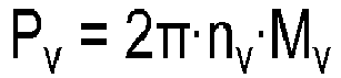
- Zur rechnerischen Ermittlung der Antriebsleistung Pv der Vorderachse besteht die Möglichkeit, dass die Kontrolleinheit das an der Vorderachse anliegende Antriebsmoment Mv bestimmt. Insbesondere ergibt sich die Antriebsleistung Pv dann durch Multiplikation des Antriebsmoments Mv mit der Raddrehzahl nv,
- Das an der Vorderachse anliegende Antriebsmoment Mv kann mittels eines zugehörigen Drehmomentsensors erfasst werden. Der Drehmomentsensor ist typischerweise als Anordnung mehrerer Dehnungsmessstreifen zur Erkennung einer an der Vorderachse antriebsmomentbedingt auftretenden Torsion ausgebildet. Alternativ kann die Erfassung des Drehmoments an der Vorderachse auch mittels eines magnetoelastischen Verfahrens erfolgen, bei dem eine torsionsbedingt auftretende Magnetfeldänderung an einem ferromagnetischen Achsenabschnitt der Vorderachse mittels zugehöriger Magnetfeldsensoren erfasst und ausgewertet wird.
- Ist zur Zuschaltung der Vorderachse eine druckgesteuerte Allradkupplung vorgesehen, so ist es auch denkbar, dass die Kontrolleinheit durch Modulation des Kupplungsschlusses einen im Rutschpunkt der Allradkupplung eingesteuerten Kupplungsdruck p ermittelt sowie das über die Allradkupplung an die Vorderachse übertragene Antriebsmoment Mv aus einem mit dem ermittelten Kupplungsdruck p korrespondierenden Losbrechmoment ableitet.
- Die Allradkupplung ist vorzugsweise in drucklosem Zustand geschlossen und verbindet den Vorderachsgetriebeabgang des Fahrzeuggetriebes mit der Vorderachse bzw. einem die Vorderräder antreibenden Vorderachsdifferential.
- Typischerweise erfolgt die Betätigung der Allradkupplung seitens der Kontrolleinheit elektrohydraulisch. Zu diesem Zweck ist die Allradkupplung über ein elektrisch steuerbares Proportionalventil mit unter Druck stehender Hydraulikflüssigkeit aus einer Hydraulikversorgung des landwirtschaftlichen Nutzfahrzeugs beaufschlagbar.
- Im Rutschpunkt ist der eingesteuerte Kupplungsdruck p im Wesentlichen proportional zu dem von der Allradkupplung an die Vorderachse übertragenen Antriebsmoment Mv. Durch Modulation des einzusteuernden Drucks p und damit des Kupplungsschlusses kann der Rutschpunkt verlässlich anhand eines Abfalls der ausgangsseitigen Drehzahl na gegenüber der eingangsseitigen Drehzahl nb der Allradkupplung erkannt werden. Da die hierfür erforderlichen Drehzahlsensoren in aller Regel bereits vorhanden sind, wird eine kostengünstige Möglichkeit zur Ermittlung der Antriebsleistung Pv der Vorderachse geschaffen.
- Genauer gesagt erfolgt die Druckeinsteuerung sukzessive bis zum Erreichen des Rutschpunkts, wobei der im Rutschpunkt eingesteuerte Kupplungsdruck p durch Auswertung eines zugehörigen elektrischen Ventilsteuerstroms I bestimmt wird. Anschließend wird der eingesteuerte Kupplungsdruck p wieder abgebaut und die Allradkupplung in ihren geschlossenen Zustand zurückversetzt.
- Die Bestimmung des Rutschpunkts erfolgt bevorzugt in regelmäßigen Zeitabständen während des Allradbetriebs, wobei die Zeitabstände insbesondere derart gewählt werden, dass ein Überhitzen der Allradkupplung ausgeschlossen ist. Die Zeitabstände liegen hierzu typischerweise im Bereich einiger Minuten.
- Bei bekannter Antriebsleistung Pv der Vorderachse kann die Antriebsleistung Ph der Hinterachse ohne Weiteres aus der von dem Dieselmotor bereitgestellten sowie im Hinblick auf anfallende Getriebeverluste korrigierten Gesamtantriebsleistung Pg abgeleitet werden,

- Die von dem Dieselmotor bereitgestellte (unkorrigierte) Gesamtantriebsleitung ergibt sich dabei aus dem momentanen Motorbetriebspunkt und kann von der Kontrolleinheit durch Auslesen einer in einem Motorsteuergerät hinterlegten Motorkennlinie bestimmt werden.
- Umgekehrt kann die Kontrolleinheit zur fahrerunabhängigen Aktivierung des Allradbetriebs eine Beurteilung eines an der Hinterachse auftretenden Antriebsradschlupfs vornehmen. Hierzu vergleicht die Kontrolleinheit die momentane Fahrtgeschwindigkeit v des landwirtschaftlichen Nutzfahrzeugs mit einer an der Hinterachse auftretenden Radumfangsgeschwindigkeit vh. Letztere ergibt sich aus dem als bekannt vorausgesetzten Reifenumfang der Hinterräder in Abhängigkeit einer zugehörigen Raddrehzahl nh.
- Für den bereits erwähnten Fall, dass das landwirtschaftliche Nutzfahrzeug über kein GPS-Navigationssystem verfügt, kann die momentane Fahrtgeschwindigkeit v auch aus den Raddrehzahlen nv der bei deaktiviertem Allradbetrieb frei laufenden Vorderräder abgeleitet werden. Ist der an der Hinterachse auftretende Antriebsradschlupf oder eine diese charakterisierende Hinterradschlupfgröße µ' größer als ein entsprechend vorgegebener Schwellenwert µ'lim, so aktiviert die Kontrolleinheit den Allradbetrieb fahrerunabhängig durch Schließen der Allradkupplung.
- Zusätzlich oder alternativ kann die Kontrolleinheit den an der Hinterachse auftretenden Antriebsradschlupf nach Maßgabe einer auf die momentane Fahrtgeschwindigkeit v des landwirtschaftlichen Nutzfahrzeugs bezogenen prozentualen Motorauslastung beurteilen. So lässt sich bei Erreichen eines Werts in der Größenordnung von 70% auf einen erhöhten Antriebsleistungsbedarf und damit auf eine entsprechende Zunahme des Antriebsradschlupfs an der Hinterachse schließen. Die auf die momentane Fahrtgeschwindigkeit v des landwirtschaftlichen Nutzfahrzeugs bezogene prozentuale Motorauslastung kann hierbei von der Kontrolleinheit aus dem momentanen Motorbetriebspunkt durch Auslesen der in dem Motorsteuergerät hinterlegten Motorkennlinie ermittelt werden.
- Die erfindungsgemäße Einrichtung wird im Folgenden anhand der beigefügten Zeichnungen näher erläutert. Es zeigen:
- Fig. 1
- ein Ausführungsbeispiel der erfindungsgemäßen Einrichtung zum Betreiben eines allradgetriebenen landwirtschaftlichen Nutzfahrzeugs,
- Fig. 2
- ein Flussdiagramm, das ein Verfahren zur Deaktivierung eines von der in
Fig. 1 dargestellten Einrichtung ausgeführten Allradbetriebs wiedergibt, und - Fig. 3
- ein Flussdiagramm, das ein Verfahren zur Aktivierung eines von der in
Fig. 1 dargestellten Einrichtung ausführbaren Allradbetriebs wiedergibt. -
Fig. 1 zeigt ein Ausführungsbeispiel der erfindungsgemäßen Einrichtung zum Betreiben eines allradgetriebenen landwirtschaftlichen Nutzfahrzeugs. - Die Einrichtung 10 ist Bestandteil eines übergeordneten Motor- bzw. Getriebemanagementsystems des landwirtschaftlichen Nutzfahrzeugs, wobei es sich bei dem landwirtschaftlichen Nutzfahrzeug beispielsgemäß um einen allradgetriebenen Traktor 12 handelt. Die Einrichtung 10 umfasst eine angetriebene Hinterachse 14 mit Hinterrädern 16 sowie eine zur Durchführung eines Allradbetriebs zuschaltbare Vorderachse 18 mit lenkbaren Vorderrädern 20. Eine mikroprozessorgesteuerte Kontrolleinheit 22 dient der Koordination des Allradbetriebs, einschließlich einer fahrerunabhängig durchgeführten Aktivierung bzw. Deaktivierung.
- Ein als Dieselmotor 24 ausgebildeter Verbrennungsmotor steht über eine Kurbelwelle mit einem Fahrzeuggetriebe 26 in Verbindung. Das Fahrzeuggetriebe 26 umfasst einen über ein Hinterachsdifferential 28 mit der Hinterachse 14 verbundenen Hinterachsgetriebeabgang 30 sowie einen über eine druckgesteuerte Allradkupplung 32 zuschaltbaren und auf diese Weise über ein Vorderachsdifferential 34 mit der Vorderachse 18 verbindbaren Vorderachsgetriebeabgang 36. Die Betätigung der Allradkupplung 32 seitens der Kontrolleinheit 22 erfolgt elektrohydraulisch. Zu diesem Zweck ist die Allradkupplung 32 über ein elektrisch steuerbares Proportionalventil 38 mit unter Druck stehender Hydraulikflüssigkeit aus einer nicht dargestellten Hydraulikversorgung des Traktors 12 beaufschlagbar. Ein mit der Kontrolleinheit 22 verbundener erster bzw. zweiter Drehzahlsensor 40 bzw. 42 dient der Erfassung einer an der Allradkupplung 32 eingangs- bzw. ausgangsseitig anliegenden Drehzahl na bzw. nb.
- Den Vorder- bzw. Hinterrädern 20 bzw. 16 des Traktors 12 zugeordnete Raddrehzahlsensoren 44 bzw. 46 dienen der Erfassung zugehöriger Raddrehzahlen nv bzw. nh, wobei die von den Raddrehzahlsensoren 44 bzw. 46 erzeugten Drehzahlsignale neben denjenigen des ersten bzw. zweiten Drehzahlsensors 40 bzw. 42 der Kontrolleinheit 22 zur Auswertung zugeführt werden.
- Des Weiteren erhält die Kontrolleinheit 22 Informationen bezüglich des momentanen Motorbetriebspunkts des Dieselmotors 24. Die Bereitstellung erfolgt seitens eines Motorsteuergeräts 48. Ein GPS-Navigationssystem 50 dient ferner der Positionserfassung des Traktors 12.
- Ein Betätigungselement 52 in Gestalt eines Schalters erlaubt eine manuelle Aktivierung bzw. Deaktivierung des Allradbetriebs, wobei der Fahrer mittels eines Anzeigeelements 54 über den jeweiligen Aktivierungszustand der Einrichtung 10 informiert wird. Bei dem Betätigungselement 52 handelt es sich beispielsgemäß um einen mechanischen Schalter, im Falle einer grafischen Bedienoberfläche ist jedoch auch eine softwaremäßige Implementierung in Gestalt eines auf einem Touchscreen eingeblendeten Bedienelements denkbar.
-
Fig. 2 zeigt ein Flussdiagramm, das ein Verfahren zur Deaktivierung eines von der inFig. 1 dargestellten Einrichtung ausgeführten Allradbetriebs wiedergibt. - Das von der Kontrolleinheit 22 durchgeführte Verfahren wird bei Erkennung eines aktivierten Allradbetriebs in einem Startschritt 100 initialisiert, wobei die Kontrolleinheit 22 in einem ersten Schritt 102 einen Zähler N auf den Wert Null setzt.
- In einem nachfolgenden zweiten Schritt 104 wird die momentane Fahrtgeschwindigkeit v des Traktors 12 gegenüber dem Erdboden ermittelt. Die momentane Fahrtgeschwindigkeit v des Traktors 12 wird von der Kontrolleinheit 22 durch Erfassung zeitlicher Positionsänderungen des Traktors 12 abgeleitet. Letztere werden der Kontrolleinheit 22 seitens des GPS-Navigationssystems 50 in Form entsprechender Positionsinformationen zur Verfügung gestellt.
- Des Weiteren ermittelt die Kontrolleinheit 22 im zweiten Schritt 104 aus dem als bekannt vorausgesetzten Reifenumfang der Vorderräder 20 in Abhängigkeit der mittels der Raddrehzahlsensoren 44 erfassten Raddrehzahl nv eine an der Vorderachse 18 auftretende Radumfangsgeschwindigkeit vv.
- Die im zweiten Schritt 104 ermittelten Geschwindigkeiten v und vv werden in einem dritten Schritt 106 zur Berechnung einer Vorderradschlupfgröße µ herangezogen, die einen an der Vorderachse 18 des Traktors 12 auftretenden Antriebsradschlupf charakterisiert, indem das Verhältnis zwischen der momentanen Fahrtgeschwindigkeit v des Traktors 12 sowie der während des Allradbetriebs am der Vorderachse 18 auftretenden Radumfangsgeschwindigkeit vv gebildet wird,

- In einem vierten Schritt 108 vergleicht die Kontrolleinheit 22 die berechnete Vorderradschlupfgröße µ mit einem vorgegebenen Schwellenwert µlim. Ist die Vorderradschlupfgröße µ kleiner oder gleich dem vorgegebenen Schwellenwert µlim, so wird mit einem fünften Schritt 110 fortgefahren, in dem dem Zähler N erneut der Wert Null zugeordnet wird. Anschließend kehrt das Verfahren zum zweiten Schritt 104 zurück.
- Erkennt die Kontrolleinheit 22 im vierten Schritt 108, dass die Vorderradschlupfgröße µ größer ist als der vorgegebene Schwellenwert µlim, so wird der Zähler N in einem sechsten Schritt 112 um den Wert Eins erhöht. Anschließend wird in einem siebten Schritt 114 geprüft, ob der Zähler N den Wert Fünf erreicht hat. Ist dies der Fall, so deaktiviert die Kontrolleinheit 22 den Allradbetrieb fahrerunabhängig durch Öffnen der Allradkupplung 32, wozu das Proportionalventil 38 in einem achten Schritt 116 in entsprechender Weise elektrisch angesteuert wird. Anschließend wird das Verfahren in einem Schlussschritt 118 beendet.
- Wird im siebten Schritt 114 hingegen festgestellt, dass der Zähler N kleiner ist als der Wert Fünf, so kehrt das Verfahren zum zweiten Schritt 104 zurück.
- Durch geeignete Vorgabe des Schwellenwerts µm lässt sich vermeiden, dass der Antrieb der Vorderachse 18 in Situationen aufrechterhalten bleibt, in denen beispielsweise aufgrund verringerter Aufstandskräfte im Bereich der Vorderachse 18 ein hinreichender Bodenkontakt der Vorderreifen des Traktors 12 nicht mehr gegeben ist. Ein Aufwühlen des Untergrunds beim Befahren von Feldern oder Grünflächen wie auch ein übermäßiger Verschleiß der Vorderreifen im Falle der Durchführung von Straßentransportfahrten kann auf diese Weise verlässlich vermieden werden.
- Dies ist insbesondere bei einer Entlastung der Vorderachse 18 infolge eines hecklastigen Fahrverhaltens des Traktors 12 von Bedeutung. Derartige Verhältnisse treten typischerweise beim Pflügen oder beim Transport von im Heckbereich angebrachten Zusatz- bzw. Anbaugeräten auf.
- Somit wird die Antriebsverbindung zur Vorderachse 18 durch Öffnen der Allradkupplung 32 ohne Zutun des Fahrers unterbrochen, sobald während des Allradbetriebs festgestellt wird, dass ein erhöhter Antriebsradschlupf an den Vorderreifen auftritt.
- Für den Fall, dass der Traktor 12 über kein GPS-Navigationssystem 50 verfügt, ist nachfolgend eine abweichende Vorgehensweise bei der Ermittlung der Vorderradschlupfgröße µ vorgesehen.
- Demgemäß bestimmt die Kontrolleinheit 22 in einem alternativen zweiten Schritt 104a zunächst das an der Vorderachse 18 des Traktors 12 anliegende Antriebsmoment Mv. Hierzu nimmt die Kontrolleinheit 22 eine gezielte Modulation des Kupplungsschlusses der Allradkupplung 32 mit dem Ziel der Bestimmung des jeweiligen Rutschpunkts vor; der Rutschpunkt repräsentiert das Losbrechmoment der Allradkupplung 32 und damit das über die Allradkupplung 32 an die Vorderachse 18 übertragene Antriebsmoment Mv.
- Im Rutschpunkt ist der eingesteuerte Kupplungsdruck p im Wesentlichen proportional zu dem von der Allradkupplung 32 an die Vorderachse 18 übertragenen Antriebsmoment Mv, erlaubt mithin dessen unmittelbare Bestimmung. Die Allradkupplung 32 ist in drucklosem Zustand geschlossen, wobei der eingesteuerte Kupplungsdruck p durch entsprechende Bestromung des Proportionalventils 38 sukzessive solange erhöht wird, bis anhand eines Abfalls der ausgangsseitigen Drehzahl na gegenüber der eingangsseitigen Drehzahl nb der Allradkupplung 32 erkannt wird, dass der Rutschpunkt erreicht ist. Daraufhin bestimmt die Kontrolleinheit 22 den im Rutschpunkt eingesteuerten Kupplungsdruck p und damit das mit dem zugehörigen Losbrechmoment korrespondierende Antriebsmoment Mv durch Auswertung eines zugehörigen elektrischen Ventilsteuerstroms I. Anschließend wird der eingesteuerte Kupplungsdruck p wieder abgebaut und die Allradkupplung 32 in ihren geschlossenen Zustand zurückversetzt.
- Ergänzend sei angemerkt, dass die Verwendung separater Drehzahlsensoren 40 und 42 zur Rutschpunktbestimmung nicht zwingend erforderlich ist, da sich ein Abfall der ausgangsseitigen Drehzahl na gegenüber der eingangsseitigen Drehzahl nb der Allradkupplung 32 auch aus einem Vergleich der von den beiden Raddrehzahlsensoren 44 und 46 erfassten Raddrehzahlen nv und nh zwischen Vorder- und Hinterachse 18 und 14 ableiten lässt.
- Die Bestimmung des Rutschpunkts erfolgt in gleichmäßigen Zeitabständen während des Allradbetriebs, und zwar bei jedem erneuten Durchlaufen des in
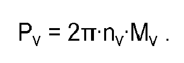
Fig. 2 dargestellten Verfahrens. Die Zeitabstände werden im Bereich von einigen Minuten derart gewählt, dass ein Überhitzen der Allradkupplung 32 ausgeschlossen ist. - Das im alternativen zweiten Schritt 104a ermittelte Antriebsmoment Mv bildet in einem nachfolgenden alternativen dritten Schritt 106a die Grundlage für die rechnerische Ermittlung der Antriebsleistung Pv der Vorderachse 18. Die Antriebsleistung Pv der Vorderachse 18 ergibt sich dann durch Multiplikation des Antriebsmoments Mv mit der Raddrehzahl nv,
- Die solchermaßen berechnete Antriebsleistung Pv dient zugleich der Ableitung der Antriebsleistung Ph der Hinterachse 14, wozu diese von der von dem Dieselmotor 24 bereitgestellten sowie im Hinblick auf anfallende Getriebeverluste korrigierten Gesamtantriebsleistung Pg subtrahiert wird,

- Die von dem Dieselmotor 24 bereitgestellte (unkorrigierte) Gesamtantriebsleistung Pg ergibt sich dabei aus dem momentanen Motorbetriebspunkt und wird von der Kontrolleinheit 22 durch Auslesen einer in dem Motorsteuergerät 48 hinterlegten Motorkennlinie bestimmt.
- Die Kontrolleinheit 22 bestimmt anschließend das Verhältnis der Antriebsleistungen Pv, Ph zwischen der Vorder- und Hinterachse 18 und 14. Das solchermaßen gebildete Verhältnis stellt einen zuverlässigen Indikator für den an den Vorderrädern 20 auftretenden Antriebsradschlupf während des Allradbetriebs dar und liegt im Idealfall in der Größenordnung von 40/60. Niedrigere Werte weisen auf eine verringerte Traktion der Vorderreifen und damit auf eine entsprechende Erhöhung des Antriebsradschlupfs an der Vorderachse 18 hin. Die Kontrolleinheit 22 leitet daher die Vorderradschlupfgröße µ im alternativen dritten Schritt 106a aus dem Verhältnis Q der rechnerisch ermittelten Antriebsleistungen Pv, Ph zwischen der Vorder- und Hinterachse 18 und 14 während des Allradbetriebs ab. Der mit der Aktivierung des Allradbetriebs korrespondierende Schwellenwert Qlimist in einem alterativen vierten Schritt 108 in der Größenordnung von 20/80 bis 30/70 vorgegeben.
- Wird daher im alternativen vierten Schritt 108a erkannt, dass das Verhältnis Q der Antriebsleistungen Pv, Ph zwischen der Vorder- und Hinterachse 18 und 14 größer ist als der vorgegebene Schwellenwert Qlim, so wird auf einen erhöhten Antriebsradschlupf an der Vorderachse 18 geschlossen, sodass mit dem sechsten Schritt 112 fortgefahren wird. Andernfalls kehrt das Verfahren nach Durchlaufen des fünften Schritts 110 zum zweiten Schritt 104 zurück, um erneut durchlaufen zu werden.
- Abweichend von der vorstehend beschriebenen Vorgehensweise kann auch eine unmittelbare Erfassung des Antriebsmoments Mv mittels eines (in
Fig. 1 nicht dargestellten) Drehmomentsensors erfolgen. Der Drehmomentsensor ist typischerweise als Anordnung mehrerer Dehnungsmessstreifen zur Erkennung einer an der Vorderachse 18 antriebsmomentbedingt auftretenden Torsion ausgebildet. -
Fig. 3 zeigt ferner ein Flussdiagramm, das ein Verfahren zur Aktivierung des von der inFig. 1 dargestellten Einrichtung ausführbaren Allradbetriebs wiedergibt. - Das von der Kontrolleinheit 22 durchgeführte Verfahren wird bei Erkennung eines deaktivierten Allradbetriebs in einem Startschritt 200 initialisiert.
- In einem ersten Schritt 202 nimmt die Kontrolleinheit 22 eine Beurteilung eines an der Hinterachse 14 auftretenden Antriebsradschlupfs vor. Hierzu vergleicht die Kontrolleinheit 22 die momentane Fahrtgeschwindigkeit v des Traktors 12 mit einer an der Hinterachse 14 auftretenden Radumfangsgeschwindigkeit vh. Letztere ergibt sich aus dem als bekannt vorausgesetzten Reifenumfang der Hinterräder 16 in Abhängigkeit der zugehörigen Raddrehzahl nh. Zur Beurteilung des Antriebsradschlupfs erfolgt die Berechnung einer diesen charakterisierenden Hinterradschlupfgröße u',

- Für den bereits erwähnten Fall, dass der Traktor 12 über kein GPS-Navigationssystem 50 verfügt, wird die momentane Fahrtgeschwindigkeit v aus den Raddrehzahlen nv der bei deaktiviertem Allradbetrieb frei laufenden Vorderräder 20 abgeleitet.
- Wird in einem zweiten Schritt 204 festgestellt, dass die Hinterradschlupfgröße µ' größer ist als ein entsprechend vorgegebener Schwellenwert µ'lim, so aktiviert die Kontrolleinheit 22 den Allradbetrieb in einem dritten Schritt 206 fahrerunabhängig durch Schließen der Allradkupplung 32. Andernfalls kehrt das Verfahren zum ersten Schritt 202 zurück.
- Ergänzend wird im zweiten Schritt 204 der an der Hinterachse 14 auftretende Antriebsradschlupf nach Maßgabe einer auf die momentane Fahrtgeschwindigkeit v des Traktors 12 bezogenen prozentualen Motorauslastung beurteilt. So lässt sich bei Erreichen eines Werts in der Größenordnung von 70% auf einen erhöhten Antriebsleistungsbedarf und damit auf eine entsprechende Zunahme des Antriebsradschlupfs an der Hinterachse 14 schließen. Die auf die momentane Fahrtgeschwindigkeit v des Traktors 12 bezogene prozentuale Motorauslastung wird hierbei von der Kontrolleinheit 22 aus dem momentanen Motorbetriebspunkt durch Auslesen der in dem Motorsteuergerät 48 hinterlegten Motorkennlinie ermittelt.
- Anschließend wird das Verfahren in einem Schlussschritt beendet.
Claims (10)
- Einrichtung zum Betreiben eines allradgetriebenen landwirtschaftlichen Nutzfahrzeugs, mit einer angetriebenen Hinterachse (14) sowie einer zur Durchführung eines Allradbetriebs zuschaltbaren Vorderachse (18), dadurch gekennzeichnet, dass eine Kontrolleinheit (22) während des Allradbetriebs eine Vorderradschlupfgröße (µ) ermittelt, die einen an der Vorderachse (18) des landwirtschaftlichen Nutzfahrzeugs (12) auftretenden Antriebsradschlupf charakterisiert, wobei die Kontrolleinheit (22) den Allradbetrieb fahrerunabhängig deaktiviert, wenn diese erkennt, dass die ermittelte Vorderradschlupfgröße (µ) größer ist als ein vorgegebener Schwellenwert (µlim).
- Einrichtung nach Anspruch 1, dadurch gekennzeichnet, dass die Kontrolleinheit (22) die Vorderradschlupfgröße (µ) aus dem Verhältnis zwischen der momentanen Fahrtgeschwindigkeit (v) des landwirtschaftlichen Nutzfahrzeugs (12) sowie einer während des Allradbetriebs an der Vorderachse (18) auftretenden Radumfangsgeschwindigkeit (vv) berechnet.
- Einrichtung nach Anspruch 1 oder 2, dadurch gekennzeichnet, dass die Kontrolleinheit (22) die Vorderradschlupfgröße (µ) aus dem Verhältnis rechnerisch ermittelter Antriebsleistungen (Pv, Ph) zwischen der Vorder- und Hinterachse (18, 14) während des Allradbetriebs ableitet.
- Einrichtung nach wenigstens einem der Ansprüche 1 bis 3, dadurch gekennzeichnet, dass die Kontrolleinheit (22) zur rechnerischen Ermittlung der Antriebsleistung (Pv) der Vorderachse (18) das an der Vorderachse (18) anliegende Antriebsmoment (Mv) bestimmt.
- Einrichtung nach Anspruch 4, dadurch gekennzeichnet, dass das an der Vorderachse (18) anliegende Antriebsmoment (Mv) mittels eines Drehmomentsensors bestimmt wird.
- Einrichtung nach Anspruch 4 oder 5, dadurch gekennzeichnet, dass zur Zuschaltung der Vorderachse (18) eine druckgesteuerte Allradkupplung (32) vorgesehen ist, wobei die Kontrolleinheit (22) durch Modulation des Kupplungsschlusses einen im Rutschpunkt der Allradkupplung (32) eingesteuerten Kupplungsdruck (p) ermittelt sowie das über die Allradkupplung (32) an die Vorderachse (18) übertragene Antriebsmoment (Mv) aus einem mit dem ermittelten Kupplungsdruck (p) korrespondierenden Losbrechmoment ableitet.
- Einrichtung nach Anspruch 6, dadurch gekennzeichnet, dass die Bestimmung des Rutschpunkts bevorzugt in regelmäßigen Zeitabständen während des Allradbetriebs erfolgt.
- Einrichtung nach wenigstens einem der Ansprüche 1 bis 7, dadurch gekennzeichnet, dass die Kontrolleinheit (22) zur fahrerunabhängigen Aktivierung des Allradbetriebs eine Beurteilung eines an der Hinterachse (14) auftretenden Antriebsradschlupfs vornimmt.
- Einrichtung nach Anspruch 8, dadurch gekennzeichnet, dass die Kontrolleinheit (22) den an der Hinterachse (14) auftretenden Antriebsradschlupf nach Maßgabe einer auf die momentane Fahrtgeschwindigkeit (v) des landwirtschaftlichen Nutzfahrzeugs (12) bezogenen prozentualen Motorauslastung beurteilt.
- Allradgetriebenes landwirtschaftliches Nutzfahrzeug, insbesondere Traktor, mit einer Einrichtung (10) nach wenigstens einem der Ansprüche 1 bis 9.
Applications Claiming Priority (1)
| Application Number | Priority Date | Filing Date | Title |
|---|---|---|---|
| DE102015212897.0A DE102015212897B4 (de) | 2015-07-09 | 2015-07-09 | Einrichtung zum Betreiben eines allradgetriebenen landwirtschaftlichen Nutzfahrzeugs |
Publications (2)
| Publication Number | Publication Date |
|---|---|
| EP3115247A1 true EP3115247A1 (de) | 2017-01-11 |
| EP3115247B1 EP3115247B1 (de) | 2022-11-23 |
Family
ID=56363756
Family Applications (1)
| Application Number | Title | Priority Date | Filing Date |
|---|---|---|---|
| EP16177890.7A Active EP3115247B1 (de) | 2015-07-09 | 2016-07-05 | Einrichtung zum betreiben eines allradgetriebenen landwirtschaftlichen nutzfahrzeugs |
Country Status (3)
| Country | Link |
|---|---|
| US (1) | US10286893B2 (de) |
| EP (1) | EP3115247B1 (de) |
| DE (1) | DE102015212897B4 (de) |
Cited By (1)
| Publication number | Priority date | Publication date | Assignee | Title |
|---|---|---|---|---|
| CN110053476A (zh) * | 2019-04-30 | 2019-07-26 | 武汉祥振科技有限公司 | 一种中央限滑差速装置、包含其的驱动系统及应用 |
Families Citing this family (9)
| Publication number | Priority date | Publication date | Assignee | Title |
|---|---|---|---|---|
| DE102017207248A1 (de) | 2017-04-28 | 2018-10-31 | Deere & Company | Verfahren zur Ermittlung einer Aufstandskraft an einem Nutzfahrzeug |
| DE102017219271A1 (de) | 2017-10-26 | 2019-05-02 | Deere & Company | Verfahren zum Betreiben eines Nutzfahrzeugs mit Allradantrieb und Differentialsperre |
| US10933742B2 (en) | 2018-12-14 | 2021-03-02 | Cnh Industrial America Llc | Operator input for alternative traction control |
| US11310955B2 (en) | 2019-07-17 | 2022-04-26 | Cnh Industrial Canada, Ltd. | Pneumatic conveying system for an agricultural product applicator |
| DE102019217330A1 (de) * | 2019-11-08 | 2021-05-12 | Zf Friedrichshafen Ag | Verfahren zum Betreiben eines Antriebsstrangs eines knickgelenkten Fahrzeugs mit wenigstens einem Differenzial |
| US12016257B2 (en) | 2020-02-19 | 2024-06-25 | Sabanto, Inc. | Methods for detecting and clearing debris from planter gauge wheels, closing wheels and seed tubes |
| US12461083B2 (en) | 2020-08-03 | 2025-11-04 | Sabanto, Inc. | Methods for improved agricultural procedures |
| ES3008734T3 (en) * | 2021-11-25 | 2025-03-25 | Bridgestone Europe Nv Sa | Tyre analysis method and system for determining characteristic parameters of an agricultural tractor |
| DE102023117970A1 (de) | 2023-07-07 | 2025-01-09 | CLAAS Tractor S.A.S | Verfahren zum Betrieb einer allradgetriebenen landwirtschaftlichen Arbeitsmaschine |
Citations (3)
| Publication number | Priority date | Publication date | Assignee | Title |
|---|---|---|---|---|
| US4718515A (en) * | 1985-08-06 | 1988-01-12 | Alfa Romeo Auto S.P.A. | Control device for a vehicle with disengageable four-wheel drive |
| US5802489A (en) * | 1994-11-14 | 1998-09-01 | Case Corporation | Front wheel drive engagement control system for agricultural vehicles |
| EP2730447A1 (de) | 2012-11-07 | 2014-05-14 | Kubota Corporation | Antriebssteuerungssystem für Arbeitsfahrzeug |
Family Cites Families (13)
| Publication number | Priority date | Publication date | Assignee | Title |
|---|---|---|---|---|
| DE3536185A1 (de) * | 1985-10-10 | 1987-04-23 | Daimler Benz Ag | Einrichtung zur generierung einer fuer die fahrgeschwindigkeit eines kraftfahrzeuges mit automatisch zu- und abschaltbarem allradantrieb repraesentativen groesse |
| DE3621225C1 (de) * | 1986-06-25 | 1987-05-27 | Daimler Benz Ag | Steuereinrichtung fuer die zeitweise Umschaltung eines Fahrzeugantriebes von einachsigem Antrieb ueber eine permanent angetriebene Fahrzeugachse auf zweiachsigen Antrieb |
| DE3744215A1 (de) * | 1987-12-24 | 1989-07-13 | Holder Gmbh & Co Geb | Mehrachsgetriebenes fahrzeug |
| JP2780717B2 (ja) * | 1989-01-24 | 1998-07-30 | 日産自動車株式会社 | 四輪駆動車の駆動力配分制御装置 |
| JPH0729558B2 (ja) * | 1989-04-10 | 1995-04-05 | 日産自動車株式会社 | 四輪駆動車の駆動力配分制御装置 |
| DE4022088A1 (de) * | 1990-07-11 | 1992-01-16 | Walterscheid Gmbh Jean | Antriebsanordnung fuer vierradgetriebene gelaendefahrzeuge, insbesondere traktoren |
| DE4138366C2 (de) * | 1991-10-19 | 1994-07-07 | Walterscheid Gmbh Gkn | Antriebsanordnung und Verfahren zur Zu- und Abschaltung des Vierradantriebes eines Fahrzeuges, insbesondere eines Traktors |
| JP3577375B2 (ja) * | 1995-09-28 | 2004-10-13 | 富士重工業株式会社 | 4輪駆動車のトラクション制御装置 |
| IT1286172B1 (it) * | 1996-07-12 | 1998-07-07 | New Holland Italia Spa | Trasmissione elettronica per un veicolo a quattro ruote motrici. |
| DE19647507A1 (de) * | 1996-11-16 | 1998-05-20 | Zahnradfabrik Friedrichshafen | Antriebssteuerung |
| JP3972431B2 (ja) * | 1997-11-05 | 2007-09-05 | トヨタ自動車株式会社 | 四輪駆動車のトラクション制御装置 |
| US20110276241A1 (en) * | 2009-01-08 | 2011-11-10 | Toyota Jidosha Kabushiki Kaisha | Control apparatus for power transmitting system of four-wheel-drive vehicle |
| SE534460C2 (sv) * | 2009-10-20 | 2011-08-30 | Bae Systems Haegglunds Ab | Förfarande för framdrivning av ett midjestyrt bandfordon |
-
2015
- 2015-07-09 DE DE102015212897.0A patent/DE102015212897B4/de active Active
-
2016
- 2016-07-05 EP EP16177890.7A patent/EP3115247B1/de active Active
- 2016-07-07 US US15/204,444 patent/US10286893B2/en active Active
Patent Citations (3)
| Publication number | Priority date | Publication date | Assignee | Title |
|---|---|---|---|---|
| US4718515A (en) * | 1985-08-06 | 1988-01-12 | Alfa Romeo Auto S.P.A. | Control device for a vehicle with disengageable four-wheel drive |
| US5802489A (en) * | 1994-11-14 | 1998-09-01 | Case Corporation | Front wheel drive engagement control system for agricultural vehicles |
| EP2730447A1 (de) | 2012-11-07 | 2014-05-14 | Kubota Corporation | Antriebssteuerungssystem für Arbeitsfahrzeug |
Cited By (1)
| Publication number | Priority date | Publication date | Assignee | Title |
|---|---|---|---|---|
| CN110053476A (zh) * | 2019-04-30 | 2019-07-26 | 武汉祥振科技有限公司 | 一种中央限滑差速装置、包含其的驱动系统及应用 |
Also Published As
| Publication number | Publication date |
|---|---|
| DE102015212897A1 (de) | 2017-01-12 |
| US20170008504A1 (en) | 2017-01-12 |
| EP3115247B1 (de) | 2022-11-23 |
| DE102015212897B4 (de) | 2024-11-14 |
| US10286893B2 (en) | 2019-05-14 |
Similar Documents
| Publication | Publication Date | Title |
|---|---|---|
| DE102015212897B4 (de) | Einrichtung zum Betreiben eines allradgetriebenen landwirtschaftlichen Nutzfahrzeugs | |
| DE10005753B4 (de) | Verfahren zur Einstellung des Lastsignals für eine Getriebeumschaltung und hierfür geeignete Getriebesteuerung | |
| EP2635447B1 (de) | Verfahren zur bestimmung der deichsellänge eines anhängers eines zugfahrzeuges | |
| DE3840397C2 (de) | ||
| EP2269880B1 (de) | Abbremsung einer Zugfahrzeug-Anhänger-Kombination | |
| DE102021123169A1 (de) | System und verfahren zum verringern eines fahrzeugwenderadius | |
| EP0288666B1 (de) | Anordnung zur Steuerung der Kraftübertragung eines allrad-angetriebenen Fahrzeugs | |
| EP2759438B1 (de) | Fahrzeugantrieb mit einem hydrostatischen Hilfsantrieb, Fahrzeug mit einem derartigen Fahrzeugantrieb und Betriebsverfahren dafür | |
| EP2725252A2 (de) | Verfahren zur Ermittlung eines Einstellparameters für eine hydraulische Aktuatoranordnung in einem Kraftfahrzeugantriebsstrang | |
| DE102017220029B4 (de) | Verfahren zum Betreiben einer Arbeitsmaschine mit einer Drehmomentmesseinrichtung | |
| DE102015202981A1 (de) | Hydrostatisch-mechanisches Leistungsverzweigungsgetriebe sowie Verfahren zum Betreiben des hydrostatisch-mechanischen Leistungsverzweigungsgetriebes | |
| DE102013106548A1 (de) | Landwirtschaftliches Fahrzeug | |
| EP2671733B1 (de) | Verfahren zum Reifendruckanpassen | |
| EP2243688A2 (de) | Korrigierte Zwangslenkung für gelenkte Anhänger/Auflieger an mehrachsgelenkten land- oder forstwirtschaftlichen Zugfahrzeugen | |
| EP4186716B1 (de) | Adaptive reifensteuerung | |
| EP1402205B1 (de) | Verfahren und system zur schlupferkennung eines umschlingungsteils eines umschlingungsgetriebes | |
| DE112008003244T5 (de) | Nutzlaststeuersystem basierend auf Kraft und Geschwindigkeit | |
| DE112016005120T5 (de) | Druck- und Drehzahlsteuerung für ein Fahrzeug | |
| DE102012011181B4 (de) | Verfahren zum Betreiben einer Antriebseinrichtung sowie entsprechendes Steuergerät | |
| DE102020211075A1 (de) | Verfahren zur traktionsbezogenen Steuerung eines Antriebsstrangs einer Arbeitsmaschine | |
| DE102011120665B4 (de) | Verfahren zum Betreiben eines Antriebssystems aufweisend eine hydrostatische Antriebseinheit | |
| DE112023003373T5 (de) | Elektrisches antriebssystem für eine maschine und elektrisches antriebssteuerungssystem für diese | |
| EP3636060A1 (de) | Verfahren zum betrieb einer arbeitsfahrzeug-arbeitsgerät-kombination, system für eine arbeitsfahrzeug-arbeitsgerät-kombination und eine arbeitsfahrzeug-arbeitsgerät-kombination | |
| DE102019206770A1 (de) | Hydrostatisches Getriebe, mobile Arbeitsmaschine mit dem Getriebe und Verfahren zur Steuerung des Getriebes | |
| EP3483019A2 (de) | Verfahren zum betreiben eines nutzfahrzeugs mit allradantrieb und differentialsperre |
Legal Events
| Date | Code | Title | Description |
|---|---|---|---|
| PUAI | Public reference made under article 153(3) epc to a published international application that has entered the european phase |
Free format text: ORIGINAL CODE: 0009012 |
|
| STAA | Information on the status of an ep patent application or granted ep patent |
Free format text: STATUS: THE APPLICATION HAS BEEN PUBLISHED |
|
| AK | Designated contracting states |
Kind code of ref document: A1 Designated state(s): AL AT BE BG CH CY CZ DE DK EE ES FI FR GB GR HR HU IE IS IT LI LT LU LV MC MK MT NL NO PL PT RO RS SE SI SK SM TR |
|
| AX | Request for extension of the european patent |
Extension state: BA ME |
|
| STAA | Information on the status of an ep patent application or granted ep patent |
Free format text: STATUS: REQUEST FOR EXAMINATION WAS MADE |
|
| 17P | Request for examination filed |
Effective date: 20170711 |
|
| RBV | Designated contracting states (corrected) |
Designated state(s): AL AT BE BG CH CY CZ DE DK EE ES FI FR GB GR HR HU IE IS IT LI LT LU LV MC MK MT NL NO PL PT RO RS SE SI SK SM TR |
|
| STAA | Information on the status of an ep patent application or granted ep patent |
Free format text: STATUS: EXAMINATION IS IN PROGRESS |
|
| 17Q | First examination report despatched |
Effective date: 20200529 |
|
| GRAP | Despatch of communication of intention to grant a patent |
Free format text: ORIGINAL CODE: EPIDOSNIGR1 |
|
| STAA | Information on the status of an ep patent application or granted ep patent |
Free format text: STATUS: GRANT OF PATENT IS INTENDED |
|
| INTG | Intention to grant announced |
Effective date: 20220713 |
|
| GRAS | Grant fee paid |
Free format text: ORIGINAL CODE: EPIDOSNIGR3 |
|
| GRAA | (expected) grant |
Free format text: ORIGINAL CODE: 0009210 |
|
| STAA | Information on the status of an ep patent application or granted ep patent |
Free format text: STATUS: THE PATENT HAS BEEN GRANTED |
|
| AK | Designated contracting states |
Kind code of ref document: B1 Designated state(s): AL AT BE BG CH CY CZ DE DK EE ES FI FR GB GR HR HU IE IS IT LI LT LU LV MC MK MT NL NO PL PT RO RS SE SI SK SM TR |
|
| REG | Reference to a national code |
Ref country code: GB Ref legal event code: FG4D Free format text: NOT ENGLISH |
|
| REG | Reference to a national code |
Ref country code: CH Ref legal event code: EP |
|
| REG | Reference to a national code |
Ref country code: DE Ref legal event code: R096 Ref document number: 502016015431 Country of ref document: DE |
|
| REG | Reference to a national code |
Ref country code: AT Ref legal event code: REF Ref document number: 1532933 Country of ref document: AT Kind code of ref document: T Effective date: 20221215 |
|
| REG | Reference to a national code |
Ref country code: IE Ref legal event code: FG4D Free format text: LANGUAGE OF EP DOCUMENT: GERMAN |
|
| REG | Reference to a national code |
Ref country code: LT Ref legal event code: MG9D |
|
| REG | Reference to a national code |
Ref country code: NL Ref legal event code: MP Effective date: 20221123 |
|
| PG25 | Lapsed in a contracting state [announced via postgrant information from national office to epo] |
Ref country code: SE Free format text: LAPSE BECAUSE OF FAILURE TO SUBMIT A TRANSLATION OF THE DESCRIPTION OR TO PAY THE FEE WITHIN THE PRESCRIBED TIME-LIMIT Effective date: 20221123 Ref country code: PT Free format text: LAPSE BECAUSE OF FAILURE TO SUBMIT A TRANSLATION OF THE DESCRIPTION OR TO PAY THE FEE WITHIN THE PRESCRIBED TIME-LIMIT Effective date: 20230323 Ref country code: NO Free format text: LAPSE BECAUSE OF FAILURE TO SUBMIT A TRANSLATION OF THE DESCRIPTION OR TO PAY THE FEE WITHIN THE PRESCRIBED TIME-LIMIT Effective date: 20230223 Ref country code: LT Free format text: LAPSE BECAUSE OF FAILURE TO SUBMIT A TRANSLATION OF THE DESCRIPTION OR TO PAY THE FEE WITHIN THE PRESCRIBED TIME-LIMIT Effective date: 20221123 Ref country code: FI Free format text: LAPSE BECAUSE OF FAILURE TO SUBMIT A TRANSLATION OF THE DESCRIPTION OR TO PAY THE FEE WITHIN THE PRESCRIBED TIME-LIMIT Effective date: 20221123 Ref country code: ES Free format text: LAPSE BECAUSE OF FAILURE TO SUBMIT A TRANSLATION OF THE DESCRIPTION OR TO PAY THE FEE WITHIN THE PRESCRIBED TIME-LIMIT Effective date: 20221123 |
|
| PG25 | Lapsed in a contracting state [announced via postgrant information from national office to epo] |
Ref country code: RS Free format text: LAPSE BECAUSE OF FAILURE TO SUBMIT A TRANSLATION OF THE DESCRIPTION OR TO PAY THE FEE WITHIN THE PRESCRIBED TIME-LIMIT Effective date: 20221123 Ref country code: PL Free format text: LAPSE BECAUSE OF FAILURE TO SUBMIT A TRANSLATION OF THE DESCRIPTION OR TO PAY THE FEE WITHIN THE PRESCRIBED TIME-LIMIT Effective date: 20221123 Ref country code: LV Free format text: LAPSE BECAUSE OF FAILURE TO SUBMIT A TRANSLATION OF THE DESCRIPTION OR TO PAY THE FEE WITHIN THE PRESCRIBED TIME-LIMIT Effective date: 20221123 Ref country code: IS Free format text: LAPSE BECAUSE OF FAILURE TO SUBMIT A TRANSLATION OF THE DESCRIPTION OR TO PAY THE FEE WITHIN THE PRESCRIBED TIME-LIMIT Effective date: 20230323 Ref country code: HR Free format text: LAPSE BECAUSE OF FAILURE TO SUBMIT A TRANSLATION OF THE DESCRIPTION OR TO PAY THE FEE WITHIN THE PRESCRIBED TIME-LIMIT Effective date: 20221123 Ref country code: GR Free format text: LAPSE BECAUSE OF FAILURE TO SUBMIT A TRANSLATION OF THE DESCRIPTION OR TO PAY THE FEE WITHIN THE PRESCRIBED TIME-LIMIT Effective date: 20230224 |
|
| PG25 | Lapsed in a contracting state [announced via postgrant information from national office to epo] |
Ref country code: NL Free format text: LAPSE BECAUSE OF FAILURE TO SUBMIT A TRANSLATION OF THE DESCRIPTION OR TO PAY THE FEE WITHIN THE PRESCRIBED TIME-LIMIT Effective date: 20221123 |
|
| PG25 | Lapsed in a contracting state [announced via postgrant information from national office to epo] |
Ref country code: SM Free format text: LAPSE BECAUSE OF FAILURE TO SUBMIT A TRANSLATION OF THE DESCRIPTION OR TO PAY THE FEE WITHIN THE PRESCRIBED TIME-LIMIT Effective date: 20221123 Ref country code: RO Free format text: LAPSE BECAUSE OF FAILURE TO SUBMIT A TRANSLATION OF THE DESCRIPTION OR TO PAY THE FEE WITHIN THE PRESCRIBED TIME-LIMIT Effective date: 20221123 Ref country code: EE Free format text: LAPSE BECAUSE OF FAILURE TO SUBMIT A TRANSLATION OF THE DESCRIPTION OR TO PAY THE FEE WITHIN THE PRESCRIBED TIME-LIMIT Effective date: 20221123 Ref country code: DK Free format text: LAPSE BECAUSE OF FAILURE TO SUBMIT A TRANSLATION OF THE DESCRIPTION OR TO PAY THE FEE WITHIN THE PRESCRIBED TIME-LIMIT Effective date: 20221123 Ref country code: CZ Free format text: LAPSE BECAUSE OF FAILURE TO SUBMIT A TRANSLATION OF THE DESCRIPTION OR TO PAY THE FEE WITHIN THE PRESCRIBED TIME-LIMIT Effective date: 20221123 |
|
| REG | Reference to a national code |
Ref country code: DE Ref legal event code: R097 Ref document number: 502016015431 Country of ref document: DE |
|
| PG25 | Lapsed in a contracting state [announced via postgrant information from national office to epo] |
Ref country code: SK Free format text: LAPSE BECAUSE OF FAILURE TO SUBMIT A TRANSLATION OF THE DESCRIPTION OR TO PAY THE FEE WITHIN THE PRESCRIBED TIME-LIMIT Effective date: 20221123 Ref country code: AL Free format text: LAPSE BECAUSE OF FAILURE TO SUBMIT A TRANSLATION OF THE DESCRIPTION OR TO PAY THE FEE WITHIN THE PRESCRIBED TIME-LIMIT Effective date: 20221123 |
|
| PLBE | No opposition filed within time limit |
Free format text: ORIGINAL CODE: 0009261 |
|
| STAA | Information on the status of an ep patent application or granted ep patent |
Free format text: STATUS: NO OPPOSITION FILED WITHIN TIME LIMIT |
|
| 26N | No opposition filed |
Effective date: 20230824 |
|
| PG25 | Lapsed in a contracting state [announced via postgrant information from national office to epo] |
Ref country code: SI Free format text: LAPSE BECAUSE OF FAILURE TO SUBMIT A TRANSLATION OF THE DESCRIPTION OR TO PAY THE FEE WITHIN THE PRESCRIBED TIME-LIMIT Effective date: 20221123 |
|
| PG25 | Lapsed in a contracting state [announced via postgrant information from national office to epo] |
Ref country code: MC Free format text: LAPSE BECAUSE OF FAILURE TO SUBMIT A TRANSLATION OF THE DESCRIPTION OR TO PAY THE FEE WITHIN THE PRESCRIBED TIME-LIMIT Effective date: 20221123 |
|
| PG25 | Lapsed in a contracting state [announced via postgrant information from national office to epo] |
Ref country code: MC Free format text: LAPSE BECAUSE OF FAILURE TO SUBMIT A TRANSLATION OF THE DESCRIPTION OR TO PAY THE FEE WITHIN THE PRESCRIBED TIME-LIMIT Effective date: 20221123 |
|
| REG | Reference to a national code |
Ref country code: CH Ref legal event code: PL |
|
| REG | Reference to a national code |
Ref country code: BE Ref legal event code: MM Effective date: 20230731 |
|
| PG25 | Lapsed in a contracting state [announced via postgrant information from national office to epo] |
Ref country code: LU Free format text: LAPSE BECAUSE OF NON-PAYMENT OF DUE FEES Effective date: 20230705 |
|
| PG25 | Lapsed in a contracting state [announced via postgrant information from national office to epo] |
Ref country code: LU Free format text: LAPSE BECAUSE OF NON-PAYMENT OF DUE FEES Effective date: 20230705 |
|
| REG | Reference to a national code |
Ref country code: IE Ref legal event code: MM4A |
|
| PG25 | Lapsed in a contracting state [announced via postgrant information from national office to epo] |
Ref country code: CH Free format text: LAPSE BECAUSE OF NON-PAYMENT OF DUE FEES Effective date: 20230731 |
|
| PG25 | Lapsed in a contracting state [announced via postgrant information from national office to epo] |
Ref country code: IT Free format text: LAPSE BECAUSE OF FAILURE TO SUBMIT A TRANSLATION OF THE DESCRIPTION OR TO PAY THE FEE WITHIN THE PRESCRIBED TIME-LIMIT Effective date: 20221123 Ref country code: BE Free format text: LAPSE BECAUSE OF NON-PAYMENT OF DUE FEES Effective date: 20230731 |
|
| PG25 | Lapsed in a contracting state [announced via postgrant information from national office to epo] |
Ref country code: IE Free format text: LAPSE BECAUSE OF NON-PAYMENT OF DUE FEES Effective date: 20230705 |
|
| PG25 | Lapsed in a contracting state [announced via postgrant information from national office to epo] |
Ref country code: IE Free format text: LAPSE BECAUSE OF NON-PAYMENT OF DUE FEES Effective date: 20230705 |
|
| REG | Reference to a national code |
Ref country code: AT Ref legal event code: MM01 Ref document number: 1532933 Country of ref document: AT Kind code of ref document: T Effective date: 20230705 |
|
| PG25 | Lapsed in a contracting state [announced via postgrant information from national office to epo] |
Ref country code: AT Free format text: LAPSE BECAUSE OF NON-PAYMENT OF DUE FEES Effective date: 20230705 |
|
| PG25 | Lapsed in a contracting state [announced via postgrant information from national office to epo] |
Ref country code: AT Free format text: LAPSE BECAUSE OF NON-PAYMENT OF DUE FEES Effective date: 20230705 |
|
| PG25 | Lapsed in a contracting state [announced via postgrant information from national office to epo] |
Ref country code: BG Free format text: LAPSE BECAUSE OF FAILURE TO SUBMIT A TRANSLATION OF THE DESCRIPTION OR TO PAY THE FEE WITHIN THE PRESCRIBED TIME-LIMIT Effective date: 20221123 |
|
| PG25 | Lapsed in a contracting state [announced via postgrant information from national office to epo] |
Ref country code: BG Free format text: LAPSE BECAUSE OF FAILURE TO SUBMIT A TRANSLATION OF THE DESCRIPTION OR TO PAY THE FEE WITHIN THE PRESCRIBED TIME-LIMIT Effective date: 20221123 |
|
| PG25 | Lapsed in a contracting state [announced via postgrant information from national office to epo] |
Ref country code: CY Free format text: LAPSE BECAUSE OF FAILURE TO SUBMIT A TRANSLATION OF THE DESCRIPTION OR TO PAY THE FEE WITHIN THE PRESCRIBED TIME-LIMIT; INVALID AB INITIO Effective date: 20160705 |
|
| PG25 | Lapsed in a contracting state [announced via postgrant information from national office to epo] |
Ref country code: HU Free format text: LAPSE BECAUSE OF FAILURE TO SUBMIT A TRANSLATION OF THE DESCRIPTION OR TO PAY THE FEE WITHIN THE PRESCRIBED TIME-LIMIT; INVALID AB INITIO Effective date: 20160705 |
|
| PGFP | Annual fee paid to national office [announced via postgrant information from national office to epo] |
Ref country code: DE Payment date: 20250620 Year of fee payment: 10 |
|
| PGFP | Annual fee paid to national office [announced via postgrant information from national office to epo] |
Ref country code: GB Payment date: 20250728 Year of fee payment: 10 |
|
| PGFP | Annual fee paid to national office [announced via postgrant information from national office to epo] |
Ref country code: FR Payment date: 20250725 Year of fee payment: 10 |
|
| PG25 | Lapsed in a contracting state [announced via postgrant information from national office to epo] |
Ref country code: TR Free format text: LAPSE BECAUSE OF FAILURE TO SUBMIT A TRANSLATION OF THE DESCRIPTION OR TO PAY THE FEE WITHIN THE PRESCRIBED TIME-LIMIT Effective date: 20221123 |