EP3114268B1 - Method for determining a loading weight of an oscillating system of a domestic appliance for treating items of laundry, and domestic appliance - Google Patents
Method for determining a loading weight of an oscillating system of a domestic appliance for treating items of laundry, and domestic appliance Download PDFInfo
- Publication number
- EP3114268B1 EP3114268B1 EP15709138.0A EP15709138A EP3114268B1 EP 3114268 B1 EP3114268 B1 EP 3114268B1 EP 15709138 A EP15709138 A EP 15709138A EP 3114268 B1 EP3114268 B1 EP 3114268B1
- Authority
- EP
- European Patent Office
- Prior art keywords
- oscillating system
- measured values
- shock absorber
- slipping
- change
- Prior art date
- Legal status (The legal status is an assumption and is not a legal conclusion. Google has not performed a legal analysis and makes no representation as to the accuracy of the status listed.)
- Active
Links
Images

Classifications
-
- D—TEXTILES; PAPER
- D06—TREATMENT OF TEXTILES OR THE LIKE; LAUNDERING; FLEXIBLE MATERIALS NOT OTHERWISE PROVIDED FOR
- D06F—LAUNDERING, DRYING, IRONING, PRESSING OR FOLDING TEXTILE ARTICLES
- D06F34/00—Details of control systems for washing machines, washer-dryers or laundry dryers
- D06F34/14—Arrangements for detecting or measuring specific parameters
- D06F34/18—Condition of the laundry, e.g. nature or weight
-
- D—TEXTILES; PAPER
- D06—TREATMENT OF TEXTILES OR THE LIKE; LAUNDERING; FLEXIBLE MATERIALS NOT OTHERWISE PROVIDED FOR
- D06F—LAUNDERING, DRYING, IRONING, PRESSING OR FOLDING TEXTILE ARTICLES
- D06F2103/00—Parameters monitored or detected for the control of domestic laundry washing machines, washer-dryers or laundry dryers
- D06F2103/02—Characteristics of laundry or load
- D06F2103/04—Quantity, e.g. weight or variation of weight
-
- D—TEXTILES; PAPER
- D06—TREATMENT OF TEXTILES OR THE LIKE; LAUNDERING; FLEXIBLE MATERIALS NOT OTHERWISE PROVIDED FOR
- D06F—LAUNDERING, DRYING, IRONING, PRESSING OR FOLDING TEXTILE ARTICLES
- D06F2103/00—Parameters monitored or detected for the control of domestic laundry washing machines, washer-dryers or laundry dryers
- D06F2103/26—Unbalance; Noise level
-
- D—TEXTILES; PAPER
- D06—TREATMENT OF TEXTILES OR THE LIKE; LAUNDERING; FLEXIBLE MATERIALS NOT OTHERWISE PROVIDED FOR
- D06F—LAUNDERING, DRYING, IRONING, PRESSING OR FOLDING TEXTILE ARTICLES
- D06F2105/00—Systems or parameters controlled or affected by the control systems of washing machines, washer-dryers or laundry dryers
-
- D—TEXTILES; PAPER
- D06—TREATMENT OF TEXTILES OR THE LIKE; LAUNDERING; FLEXIBLE MATERIALS NOT OTHERWISE PROVIDED FOR
- D06F—LAUNDERING, DRYING, IRONING, PRESSING OR FOLDING TEXTILE ARTICLES
- D06F37/00—Details specific to washing machines covered by groups D06F21/00 - D06F25/00
- D06F37/20—Mountings, e.g. resilient mountings, for the rotary receptacle, motor, tub or casing; Preventing or damping vibrations
- D06F37/22—Mountings, e.g. resilient mountings, for the rotary receptacle, motor, tub or casing; Preventing or damping vibrations in machines with a receptacle rotating or oscillating about a horizontal axis
Definitions
- the invention relates to a method for determining a loading weight of a vibrating system of a domestic appliance for the care of laundry, in which vibrations of the oscillating system are attenuated by means of at least one shock absorber against a device housing of the household appliance, and wherein by means of a displacement sensor measured values are provided which a displacement indicate the oscillating system with respect to a reference position, and the determination of the loading weight by means of a control device based on the measured values takes place.
- the invention also relates to a domestic appliance for the care of laundry items, which is designed for carrying out such a method.
- the laundry care device here includes a detection device which serves to detect an operating parameter, namely in particular a water load of a laundry container.
- the detection device is coupled to a capacitor whose capacitance is correlated with the operating parameter.
- a capacitor a film capacitor is used here, which in contrast to a conventional capacitor has a much smaller space requirement and can be arranged due to its geometric flexibility without much effort in an optimal position within the household appliance. This will improve the detection of the Operating parameters ensured.
- one electrode of the film capacitor are fixed in position to a housing of the household appliance and the other electrode or the counter electrode are fixed in position to the tub. In this way, in addition to determining the water load as a function of the geometric arrangement of the two electrodes, the position or the movement of the tub inside the housing can be determined, whereby a total load of the tub and a static and dynamic imbalance can be determined.
- the document DE 101 04 682 B4 describes a method for measuring the loading and unbalance of the drum of a washing machine, wherein the capacitance curve of a capacitive sensor during a washing process measured and from the movement of the tub is determined.
- at least one conductive surface of the sensor is electrically isolated as a capacitive sensor between the tub and the device housing fixed to the housing attached.
- the interest is directed to the determination of the loading or a loading weight of the washing drum of a washing machine, in particular to the detection of the so-called dry mass of laundry items, which are introduced by the user into the laundry drum.
- the commonly used method uses the measurement of the movement of the spring-loaded oscillating system with increasing load for determining the mass in the drum.
- a symmetrical system with a one-dimensional sensor is in this regard, for example, in the document DE 10 2009 028 772 A1 described.
- Another method which can also be used for asymmetrical systems for determining a loading amount of a laundry treatment appliance is disclosed in the document DE 10 2006 034 190 A1 known.
- the use of a displacement sensor for determining the load weight of a washing machine is further from the document DE 10 2004 043 838 B3 known.
- the evaluation of the measured values of the displacement sensor takes place in such a way that the rest position of the oscillating system is detected and stored with the aid of the displacement sensor, and the control is switched into the active mode when the detected values change.
- the detected rest position of the oscillating system is taken into account.
- the determination of the rest position thus takes place here in the time in which the control unit is inactive, that is in sleep mode.
- the displacement sensor is read in at least once again, this value read in under load being subtracted from the value for the rest position detected in sleep mode and the result from this calculation being used as weight for the laundry.
- An inventive method is used to determine a loading weight of a vibrating system of a household appliance for the care of laundry.
- at least one shock absorber - this is designed as a spring piston friction damper - vibrations of the oscillating system are damped against a housing of the household appliance.
- measured values are provided which indicate a displacement of the oscillating system - in particular in the vertical direction of the domestic appliance - with respect to a reference position, ie. a relative position with respect to the reference position.
- the determination of the loading weight is carried out on the basis of the measured values by means of an electronic control device, which can be designed, for example, as a digital signal processor.
- a temporal course of the measured values is evaluated by the control device and, based on the chronological progression, slippage of the shock absorber during loading of the oscillating system is detected is, wherein a caused by the slipping change value of the displacement is determined by the control device and compensated in the determination of the loading weight.
- the invention is based on the finding that the measurement of the load weight in a domestic appliance for the care of laundry items is adversely affected by slippage of a friction lining of the shock absorber. This slippage can occur in particular during the loading process. Another finding is that slippage of the friction lining of the shock absorber generates a typical course of the measured values of the displacement sensor. This typical waveform can detected during the loading process by the control device and interpreted as slippage of the friction lining. If such slipping is detected, an offset value or a change value of the displacement is simultaneously determined and compensated for in the determination of the loading weight.
- the force impressed into the system by the shock absorber is fundamentally dependent on the lowering of the oscillating system.
- the weight of the oscillating system including loading is in equilibrium with the spring forces of a spring assembly and the impressed by the at least one shock absorber forces.
- a change in position is compensated, which results by changing the equilibrium when the at least one shock absorber comes in a non-linear working area and slips.
- the invention has the advantage that the total loading weight can be determined very precisely, since the main disturbing influence of the loading amount - namely the nonlinear damping force - is compensated. It can also be used with a lower stiction spring piston damper, which has particular advantages in terms of noise reduction. Accordingly, costly, speed-dependent dampers, such as oil hydraulic dampers, do not need to be used.
- the slippage of the shock absorber is detected when a change in the displacement of the oscillating system which is greater than a predetermined limit value is detected based on the time profile of the measured values within a time interval of a predetermined length.
- This embodiment is based on the recognition that a large change in the position of the oscillating system within a very short time interval can basically only be caused by the slipping of the shock absorber, but not by the introduction of the laundry items in the laundry drum. If the position of the oscillating system changes abruptly within, for example, two milliseconds, it can be assumed that this change in position is due to the slipping friction lining and not to an additional load. Thus, the slippage of the shock absorber can be detected particularly reliable and the load weight can be precisely determined.
- this can also be implemented in such a way that, based on the chronological course of the measured values, a rate of change as a change in the shift per Time unit is determined by the controller.
- the detection of the slipping of the shock absorber can then be made depending on the rate of change. If the rate of change exceeds a predetermined limit, slippage is detected because it is unlikely that a relatively high rate of change can be caused by the introduction of laundry into the laundry drum.
- a household appliance for the care of items of laundry is understood in particular a washing machine or a washer-dryer.
- the oscillating system comprises in particular a tub, which is supported on the at least one shock absorber and in particular suspended on a spring assembly.
- the oscillating system also includes in particular a laundry drum, which is rotatably mounted in the tub.
- a displacement sensor is understood to mean a sensor which is designed to detect the altitude of the oscillating system.
- This displacement sensor can be based on any physical principle, for example on optical and / or electrical and / or electromechanical and / or electromagnetic effects.
- the output signal of the displacement sensor may be an analog or a digital signal.
- a “slippage of the shock absorber” in the present case is understood to mean a movement or slippage of a friction lining of the damper relative to its friction partner, in particular a cylinder of the damper.
- a shock absorber in particular a damper can be used, as in the document DE 10 2010 042 173 A1 is described.
- the displacement of the oscillating system is detected by means of the displacement sensor relative to a reference position of the system.
- this reference position can be a rest position of the oscillating system that occurs in an unloaded system.
- This rest position can be detected, for example, after completion of each operating program after unloading the laundry drum.
- a dry mass of laundry items is determined as the load weight, which is introduced into the laundry drum of the oscillating system. This means that the loading weight of the laundry drum is determined before activating an operating program of the household appliance.
- the control device determines the abovementioned change value of the offset, which is compensated in the determination of the loading weight. This can in particular be effected in such a way that the change value of the displacement caused by the slippage is subtracted from a current measured value of the displacement sensor (after slipping) and the loading weight is determined as a function of the subtraction result. A distortion of the load weight can thus be prevented.
- the invention also relates to a domestic appliance for the care of laundry items, comprising a vibrating system including a laundry drum for holding the laundry items, with at least one shock absorber for damping vibrations of the oscillating system against a housing of the household appliance, with at least one displacement sensor for providing measured values indicate a displacement of the oscillating system relative to a reference position, and with a control device for determining a loading weight of the oscillating system on the basis of the measured values.
- the control device is designed to evaluate a time characteristic of the measured values during a loading process of the oscillating system (16), to detect, based on the time course, slippage of the shock absorber during loading of the oscillating system, to determine a change value of the displacement caused by the slipping to compensate for the determination of the loading weight and then to detect slippage, if, based on the time profile of the measured values, a change in the displacement within a time interval of a predetermined length is detected, which is greater than a predefined limit value.
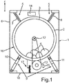
- An in Fig. 1 illustrated household appliance 1 is a washing machine in the embodiment.
- the household appliance 1 comprises a tub 2, in which a laundry drum 3 is rotatably mounted.
- laundry items 4 which are washed in the household appliance 1 during a care process.
- the tub 2 is suspended by a spring assembly 5 on a device housing 6 of the household appliance 1.
- the spring arrangement 5 comprises a first and a second spring 7, 8, wherein the number of springs can be basically arbitrary.
- the tub 2 is further supported on a damper assembly 9, which in the embodiment comprises a first and a second shock absorber 10, 11.
- the shock absorbers 10, 11 are friction dampers.
- the number of shock absorbers 10, 11 used can basically be chosen arbitrarily.
- the damper assembly 9 may also include three or four such shock absorbers 10, 11.
- the laundry drum 3 is rotatably mounted in the tub 2 about a horizontally extending axis of rotation 12 and is driven by means of an electric drive motor 13.
- a rotor of the drive motor 13 may be connected, for example via a belt with the laundry drum 3 in a conventional manner.
- the tub 2 and the laundry drum 3 form a total of a vibrating system 16 which is suspended via the springs 7, 8 movable in the device housing 6.
- the shock absorbers 10, 11 are used for damping large amplitudes.
- a central control device 14 and an electronic engine control unit 15 are further arranged. While the central electronic control device 14 is used to control the care processes of the household appliance 1 and thus represents a higher-level control device, it is the task of the motor control unit 15 to control the electric drive motor 13. For example, while the speed of the drive motor 13 is controlled by means of the engine control unit 15.
- the central control device 14 can communicate with the engine control unit 15, for example via a communication bus, not shown, or wirelessly.
- the central control device 14 For controlling the care processes of the household appliance 1, the central control device 14 requires information about the current parameter values of various operating parameters of the household appliance 1, in particular information about the load weight or the dry mass of the laundry items 4.
- a displacement sensor 17 is used, which is located between the vibrating System 16 on the one hand and a bottom 18 of the device housing 6 is clamped and detects the movement of the tub 2 and the entire oscillating system 16 relative to the device housing 6 in the vertical direction z and thus perpendicular to the axis of rotation 12 or optionally in several dimensions.
- the Distance sensor 17 detects a current position or displacement of the oscillating system 16 with respect to a reference position, which corresponds in particular to a rest position of the oscillating system 16.
- the measured values provided by the displacement sensor 17 are transmitted to the control device 14, which then uses these measured values to determine the current load weight.
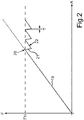
- Fig. 2 shows the dependence of a force F introduced by the shock absorbers 10, 11 into the oscillating system 16 from a depression A of the oscillating system 16.
- the weight of the vibrating system 16, including loading is in equilibrium with the forces of the springs 7, 8 and the force F. impressed by the shock absorbers 10, 11.
- the linear course of the section 19 shows that the springs of the shock absorbers 10, 11 are continuously tensioned.
- a static friction FH of the shock absorbers 10, 11 is overcome, and the friction lining slips through, which can be recognized by a further section 21, in which the force F decreases.
- section 22 the spring of the respective shock absorber 10, 11 stretched again, wherein after reaching the static friction FH, the friction lining again slips. The slippage takes place within a very small time interval T.
- the interest in the present case is the compensation of the determination of the load weight due to a change in the equilibrium when the shock absorbers 10, 11 come into their non-linear working range and slip.
- the control device 14 evaluates the time profile of the measured values of the displacement sensor 17. The control device 14 checks whether a very large change in the measured values occurs within a very short time interval. If such a change is detected within a very short time - for example within two milliseconds - it can be assumed with very high probability that this change is due to a slipping shock absorber 10, 11.
- the measured value changes can basically be assigned to three possible causes:
- the rate of change v is nearly zero and thus less than a predetermined first limit G1: a low rate of change indicates a change in the load weight and thus a conventional user loading action.
- the rate of change v is greater than the first threshold G1 and less than a higher second threshold G2.
- This moderate rate of change v indicates manual manipulation of the vibrating system 16 by the user, which is ignored by the controller 14 herein. This position change of the oscillating system 16 is thus not corrected in the determination of the load weight.
- the rate of change v is very large and therefore greater than the second limit G2: If this is detected, it is assumed that a slipping shock absorber 10, 11. Slippage of the shock absorber 10, 11, i. A displacement of the position of the friction lining within the shock absorber 10, 11, namely, exists when the measured values of the displacement sensor 17 change very quickly, which can be detected by the control device 14 on the basis of the rate of change v.
- FIG Fig. 3 A typical dependency of the measured loading weight B on the actual load or the actual weight B 'of the introduced laundry items 4 is shown in FIG Fig. 3 shown. How out Fig. 3 shows that the rate of change v is initially relatively low and almost equal to zero. As indicated at 23, the position or displacement of the oscillating system 16 changes abruptly upon reaching the stiction of the shock absorbers 10, 11. Upon detection of this slippage, the controller 14 determines a change value 24 of the position of the oscillating system 16 caused by slippage This change value 24 represents an offset, which is then compensated in the determination of the loading weight B. The result of the determination of the loading weight B without this compensation is in Fig. 3 denoted by 25.
- a Loading weight B determined by the control device 14 which is much more realistic.
- the loading weight B with the compensation according to the invention is in Fig. 3 denoted by 26. How out Fig. 3 In the context of the compensation, the determined change value 24 is deducted from the current measured values of the displacement sensor 17 detected after the detection of slippage.
Description
Die Erfindung betrifft ein Verfahren zum Bestimmen eines Beladungsgewichts eines schwingenden Systems eines Haushaltsgeräts zur Pflege von Wäschestücken, bei welchem Schwingungen des schwingenden Systems mittels zumindest eines Stoßdämpfers gegen ein Gerätegehäuse des Haushaltsgeräts gedämpft werden, und bei welchem mittels eines Wegsensors Messwerte bereitgestellt werden, welche eine Verschiebung des schwingenden Systems gegenüber einer Referenzposition angeben, und das Bestimmen des Beladungsgewichts mittels einer Steuereinrichtung anhand der Messwerte erfolgt. Die Erfindung betrifft außerdem ein Haushaltsgerät zur Pflege von Wäschestücken, welches zum Durchführen eines solchen Verfahrens ausgebildet ist.The invention relates to a method for determining a loading weight of a vibrating system of a domestic appliance for the care of laundry, in which vibrations of the oscillating system are attenuated by means of at least one shock absorber against a device housing of the household appliance, and wherein by means of a displacement sensor measured values are provided which a displacement indicate the oscillating system with respect to a reference position, and the determination of the loading weight by means of a control device based on the measured values takes place. The invention also relates to a domestic appliance for the care of laundry items, which is designed for carrying out such a method.
Es ist bei Haushaltsgeräten zur Pflege von Wäschestücken, wie insbesondere bei Waschmaschinen, üblich, die Bewegung des Laugenbehälters relativ zum Gerätegehäuse zu erfassen. Wird die Bewegung des Laugenbehälters gemessen, kann auf die Beladung der Wäschetrommel zurückgeschlossen werden. Andererseits kann abhängig von der erfassten Bewegung des Laugenbehälters auch eine Unwucht der Wäschetrommel bzw. des gesamten Schwingsystems im Schleuderbetrieb detektiert werden. Es ist bereits Stand der Technik, zur Erfassung der Bewegung eines Laugenbehälters kapazitive Sensoren einzusetzen, welche die Bewegung des Laugenbehälters relativ zum Gerätegehäuse auf kapazitivem Wege messen. Ein derartiges Haushaltsgerät ist beispielsweise aus dem Dokument
Auch das Dokument
Vorliegend richtet sich das Interesse auf die Bestimmung der Beladung bzw. eines Beladungsgewichts der Wäschetrommel einer Waschmaschine, insbesondere auf die Erfassung der sogenannten Trockenmasse von Wäschestücken, welche durch den Benutzer in die Wäschetrommel eingebracht werden. Das üblicherweise verwendete Verfahren nutzt dabei die Messung der Bewegung des federnd aufgehängten Schwingsystems unter zunehmender Beladungsmenge zur Bestimmung der in der Trommel befindlichen Masse. Ein symmetrisches System mit einem eindimensionalen Sensor ist diesbezüglich beispielsweise in der Druckschrift
In der
Der Einsatz eines Wegsensors zur Bestimmung des Beladungsgewichts einer Waschmaschine ist des Weiteren aus dem Dokument
Ferner ist aus
Es ist Aufgabe der Erfindung, eine Lösung aufzuzeigen, wie bei einem Verfahren der eingangs genannten Gattung die Bestimmung des Beladungsgewichts besonders präzise erfolgen kann.It is an object of the invention to provide a solution, as in a method of the type mentioned in the determination of the load weight can be carried out very precisely.
Diese Aufgabe wird erfindungsgemäß durch ein Verfahren sowie durch ein Haushaltsgerät mit den Merkmalen gemäß den jeweiligen unabhängigen Patentansprüchen gelöst. Vorteilhafte Ausführungen der Erfindung sind Gegenstand der abhängigen Patentansprüche, der Beschreibung und der Figuren.This object is achieved by a method and by a household appliance with the features according to the respective independent claims. Advantageous embodiments of the invention are the subject of the dependent claims, the description and the figures.
Ein erfindungsgemäßes Verfahren dient zum Bestimmen eines Beladungsgewichts eines schwingenden Systems eines Haushaltsgeräts zur Pflege von Wäschestücken. Mittels zumindest eines Stoßdämpfers - dieser ist als Federkolben-Reibdämpfer ausgebildet - werden Schwingungen des schwingenden Systems gegen ein Gehäuse des Haushaltsgeräts gedämpft. Mittels eines Wegsensors werden Messwerte bereitgestellt, welche eine Verschiebung des schwingenden Systems - insbesondere in Hochrichtung des Haushaltsgeräts - gegenüber einer Referenzposition angegeben, d.h. eine relative Position bezüglich der Referenzposition. Das Bestimmen des Beladungsgewichts erfolgt anhand der Messwerte mittels einer elektronischen Steuereinrichtung, welche beispielsweise als digitaler Signalprozessor ausgebildet sein kann. Erfindungsgemäß ist vorgesehen, dass während eines Beladungsvorgangs des schwingenden Systems - insbesondere während ein Benutzer die Wäschestücke in eine Wäschetrommel des Systems einbringt - ein zeitlicher Verlauf der Messwerte durch die Steuereinrichtung ausgewertet wird und anhand des zeitlichen Verlaufs ein Durchrutschen des Stoßdämpfers beim Beladen des schwingenden Systems detektiert wird, wobei ein durch das Durchrutschen verursachter Änderungswert der Verschiebung durch die Steuereinrichtung bestimmt und bei der Bestimmung des Beladungsgewichts kompensiert wird.An inventive method is used to determine a loading weight of a vibrating system of a household appliance for the care of laundry. By means of at least one shock absorber - this is designed as a spring piston friction damper - vibrations of the oscillating system are damped against a housing of the household appliance. By means of a displacement sensor, measured values are provided which indicate a displacement of the oscillating system - in particular in the vertical direction of the domestic appliance - with respect to a reference position, ie. a relative position with respect to the reference position. The determination of the loading weight is carried out on the basis of the measured values by means of an electronic control device, which can be designed, for example, as a digital signal processor. According to the invention, during a loading process of the oscillating system-in particular while a user is placing the items of laundry in a laundry drum of the system-a temporal course of the measured values is evaluated by the control device and, based on the chronological progression, slippage of the shock absorber during loading of the oscillating system is detected is, wherein a caused by the slipping change value of the displacement is determined by the control device and compensated in the determination of the loading weight.
Die Erfindung beruht auf der Erkenntnis, dass die Messung des Beladungsgewichts bei einem Haushaltsgerät zur Pflege von Wäschestücken durch ein Durchrutschen eines Reibbelags des Stoßdämpfers negativ beeinflusst wird. Dieses Durchrutschen kann insbesondere auch während des Beladungsvorgangs auftreten. Eine weitere Erkenntnis besteht darin, dass ein Durchrutschen des Reibbelags des Stoßdämpfers einen typischen Verlauf der Messwerte des Wegsensors erzeugt. Dieser typische Signalverlauf kann während des Beladungsvorgangs durch die Steuereinrichtung detektiert und als Durchrutschen des Reibbelags interpretiert werden. Wird ein solches Durchrutschen detektiert, so wird gleichzeitig auch ein Offsetwert bzw. ein Änderungswert der Verschiebung bestimmt und bei der Bestimmung des Beladungsgewichts kompensiert. Die von dem Stoßdämpfer in das System eingeprägte Kraft ist grundsätzlich abhängig von der Absenkung des schwingenden Systems. Die Gewichtskraft des schwingenden Systems inklusive Beladung ist im Gleichgewicht mit den Federkräften einer Federanordnung und den von dem zumindest einen Stoßdämpfer eingeprägten Kräften. Durch die Erfindung wird eine Positionsänderung kompensiert, die sich durch Veränderung des Gleichgewichts ergibt, wenn der zumindest eine Stoßdämpfer in einen nichtlinearen Arbeitsbereich kommt und durchrutscht. Die Erfindung hat insgesamt den Vorteil, dass das Beladungsgewicht insgesamt sehr präzise bestimmt werden kann, da der hauptsächliche Störeinfluss der Beladungsmenge - nämlich die nichtlineare Dämpferkraft - kompensiert wird. Es können des Weiteren Federkolbendämpfer mit einer geringeren Haftreibung eingesetzt werden, was insbesondere Vorteile hinsichtlich der Geräuschminimierung hat. Entsprechend brauchen kostenintensive, geschwindigkeitsabhängige Dämpfer, wie beispielsweise Ölhydraulikdämpfer, nicht eingesetzt zu werden.The invention is based on the finding that the measurement of the load weight in a domestic appliance for the care of laundry items is adversely affected by slippage of a friction lining of the shock absorber. This slippage can occur in particular during the loading process. Another finding is that slippage of the friction lining of the shock absorber generates a typical course of the measured values of the displacement sensor. This typical waveform can detected during the loading process by the control device and interpreted as slippage of the friction lining. If such slipping is detected, an offset value or a change value of the displacement is simultaneously determined and compensated for in the determination of the loading weight. The force impressed into the system by the shock absorber is fundamentally dependent on the lowering of the oscillating system. The weight of the oscillating system including loading is in equilibrium with the spring forces of a spring assembly and the impressed by the at least one shock absorber forces. By the invention, a change in position is compensated, which results by changing the equilibrium when the at least one shock absorber comes in a non-linear working area and slips. Overall, the invention has the advantage that the total loading weight can be determined very precisely, since the main disturbing influence of the loading amount - namely the nonlinear damping force - is compensated. It can also be used with a lower stiction spring piston damper, which has particular advantages in terms of noise reduction. Accordingly, costly, speed-dependent dampers, such as oil hydraulic dampers, do not need to be used.
Das Durchrutschen des Stoßdämpfers wird dann detektiert, wenn anhand des zeitlichen Verlaufs der Messwerte innerhalb eines Zeitintervalls vorgegebener Länge eine Änderung der Verschiebung des schwingenden Systems detektiert wird, welche größer als ein vorgegebener Grenzwert ist. Diese Ausführungsform basiert auf der Erkenntnis, dass eine große Änderung der Position des schwingenden Systems innerhalb eines sehr kurzen Zeitintervalls grundsätzlich ausschließlich durch das Durchrutschen des Stoßdämpfers verursacht werden kann, nicht jedoch durch das Einbringen der Wäschestücke in die Wäschetrommel. Ändert sich die Position des schwingenden Systems abrupt innerhalb von beispielsweise zwei Millisekunden, so kann davon ausgegangen werden, dass diese Änderung der Lage auf den durchrutschenden Reibbelag und nicht auf eine zusätzliche Beladung zurückzuführen ist. Somit kann das Durchrutschen des Stoßdämpfers besonders zuverlässig detektiert und das Beladungsgewicht präzise bestimmt werden.The slippage of the shock absorber is detected when a change in the displacement of the oscillating system which is greater than a predetermined limit value is detected based on the time profile of the measured values within a time interval of a predetermined length. This embodiment is based on the recognition that a large change in the position of the oscillating system within a very short time interval can basically only be caused by the slipping of the shock absorber, but not by the introduction of the laundry items in the laundry drum. If the position of the oscillating system changes abruptly within, for example, two milliseconds, it can be assumed that this change in position is due to the slipping friction lining and not to an additional load. Thus, the slippage of the shock absorber can be detected particularly reliable and the load weight can be precisely determined.
Dies kann praktisch auch derart umgesetzt werden, dass anhand des zeitlichen Verlaufs der Messwerte eine Änderungsgeschwindigkeit als eine Änderung der Verschiebung pro Zeiteinheit durch die Steuereinrichtung bestimmt wird. Das Detektieren des Durchrutschens des Stoßdämpfers kann dann abhängig von der Änderungsgeschwindigkeit vorgenommen werden. Überschreitet die Änderungsgeschwindigkeit einen vorgegebenen Grenzwert, so wird das Durchrutschen detektiert, da es eher unwahrscheinlich ist, dass eine relativ hohe Änderungsgeschwindigkeit durch das Einbringen von Wäschestücken in die Wäschetrommel verursacht werden kann.In practice, this can also be implemented in such a way that, based on the chronological course of the measured values, a rate of change as a change in the shift per Time unit is determined by the controller. The detection of the slipping of the shock absorber can then be made depending on the rate of change. If the rate of change exceeds a predetermined limit, slippage is detected because it is unlikely that a relatively high rate of change can be caused by the introduction of laundry into the laundry drum.
Unter einem Haushaltsgerät zur Pflege von Wäschestücken wird insbesondere eine Waschmaschine oder ein Waschtrockner verstanden.Under a household appliance for the care of items of laundry is understood in particular a washing machine or a washer-dryer.
Das schwingende System umfasst insbesondere einen Laugenbehälter, welcher an dem zumindest einen Stoßdämpfer abgestützt und insbesondere auch auf einer Federanordnung aufgehängt ist. Zum schwingenden System gehört insbesondere auch eine Wäschetrommel, welche in dem Laugenbehälter drehbar gelagert ist.The oscillating system comprises in particular a tub, which is supported on the at least one shock absorber and in particular suspended on a spring assembly. The oscillating system also includes in particular a laundry drum, which is rotatably mounted in the tub.
Unter einem Wegsensor wird vorliegend ein Sensor verstanden, welcher zum Erfassen der Höhenlage des schwingenden Systems ausgebildet ist. Dieser Wegsensor kann auf einem beliebigen physikalischen Prinzip beruhen, beispielsweise auf optischen und/oder elektrischen und/oder elektromechanischen und/oder elektromagnetischen Wirkungen. Das Ausgangssignal des Wegsensors kann ein analoges oder ein digitales Signal sein.In the present case, a displacement sensor is understood to mean a sensor which is designed to detect the altitude of the oscillating system. This displacement sensor can be based on any physical principle, for example on optical and / or electrical and / or electromechanical and / or electromagnetic effects. The output signal of the displacement sensor may be an analog or a digital signal.
Unter einem "Durchrutschen des Stoßdämpfers" wird vorliegend eine Bewegung bzw. ein Rutschen eines Reibbelages des Dämpfers relativ zu seinem Reibpartner, insbesondere einem Zylinder des Dämpfers, verstanden. Als Stoßdämpfer kann insbesondere ein Dämpfer eingesetzt werden, wie er im Dokument
Die Verschiebung des schwingenden Systems wird mittels des Wegsensors relativ zu einer Referenzposition des Systems erfasst. Bei dieser Referenzposition kann es sich insbesondere um eine Ruhestellung des schwingenden Systems handeln, die sich bei einem unbeladenen System einstellt. Diese Ruhestellung kann beispielsweise nach Abschluss jedes Betriebsprogramms nach Entladung der Wäschetrommel erfasst werden.The displacement of the oscillating system is detected by means of the displacement sensor relative to a reference position of the system. In particular, this reference position can be a rest position of the oscillating system that occurs in an unloaded system. This rest position can be detected, for example, after completion of each operating program after unloading the laundry drum.
In einer Ausführungsform ist vorgesehen, dass als Beladungsgewicht eine Trockenmasse von Wäschestücken bestimmt wird, welche in die Wäschetrommel des schwingenden Systems eingebracht werden. Dies bedeutet, dass das Beladungsgewicht der Wäschetrommel noch vor dem Aktivieren eines Betriebsprogramms des Haushaltsgeräts bestimmt wird.In one embodiment, it is provided that a dry mass of laundry items is determined as the load weight, which is introduced into the laundry drum of the oscillating system. This means that the loading weight of the laundry drum is determined before activating an operating program of the household appliance.
Wird das Durchrutschen detektiert, so bestimmt die Steuereinrichtung den oben genannten Änderungswert der Verschiebung (Offset), welcher bei der Bestimmung des Beladungsgewichts kompensiert wird. Dies kann insbesondere derart erfolgen, dass der durch das Durchrutschen verursachte Änderungswert der Verschiebung von einem aktuellen Messwert des Wegsensors (nach dem Durchrutschen) subtrahiert wird und das Beladungsgewicht abhängig von dem Subtraktionsergebnis bestimmt wird. Eine Verfälschung des Beladungsgewichts kann somit verhindert werden.If the slippage is detected, the control device determines the abovementioned change value of the offset, which is compensated in the determination of the loading weight. This can in particular be effected in such a way that the change value of the displacement caused by the slippage is subtracted from a current measured value of the displacement sensor (after slipping) and the loading weight is determined as a function of the subtraction result. A distortion of the load weight can thus be prevented.
Die Erfindung betrifft außerdem ein Haushaltsgerät zur Pflege von Wäschestücken, mit einem schwingenden System einschließlich einer Wäschetrommel zur Aufnahme der Wäschestücke, mit zumindest einem Stoßdämpfer zum Dämpfen von Schwingungen des schwingenden Systems gegen ein Gehäuse des Haushaltsgeräts, mit zumindest einem Wegsensor zum Bereitstellen von Messwerten, welche eine Verschiebung des schwingenden Systems gegenüber einer Referenzposition angeben, und mit einer Steuereinrichtung zum Bestimmen eines Beladungsgewichts des schwingenden Systems anhand der Messwerte. Die Steuereinrichtung ist dazu ausgelegt, während eines Beladungsvorgangs des schwingenden Systems (16) einen zeitlichen Verlauf der Messwerte auszuwerten, anhand des zeitlichen Verlaufs ein Durchrutschen des Stoßdämpfers beim Beladen des schwingenden Systems zu detektieren, einen durch das Durchrutschen verursachten Änderungswert der Verschiebung zu bestimmen, bei der Bestimmung des Beladungsgewichts zu kompensieren und ein Durchrutschen dann zu detektierten, wenn anhand des zeitlichen Verlaufs der Messwerte eine Änderung der Verschiebung innerhalb eines Zeitintervalls vorgegebener Länge detektiert wird, welche größer als ein vorgegebener Grenzwert ist.The invention also relates to a domestic appliance for the care of laundry items, comprising a vibrating system including a laundry drum for holding the laundry items, with at least one shock absorber for damping vibrations of the oscillating system against a housing of the household appliance, with at least one displacement sensor for providing measured values indicate a displacement of the oscillating system relative to a reference position, and with a control device for determining a loading weight of the oscillating system on the basis of the measured values. The control device is designed to evaluate a time characteristic of the measured values during a loading process of the oscillating system (16), to detect, based on the time course, slippage of the shock absorber during loading of the oscillating system, to determine a change value of the displacement caused by the slipping to compensate for the determination of the loading weight and then to detect slippage, if, based on the time profile of the measured values, a change in the displacement within a time interval of a predetermined length is detected, which is greater than a predefined limit value.
Die mit Bezug auf das erfindungsgemäße Verfahren vorgestellten bevorzugten Ausführungsformen und deren Vorteile gelten entsprechend für das erfindungsgemäße Haushaltsgerät.The preferred embodiments presented with reference to the method according to the invention and their advantages apply correspondingly to the household appliance according to the invention.
Weitere Merkmale der Erfindung ergeben sich aus den Ansprüchen, den Figuren und der Figurenbeschreibung. Alle vorstehend in der Beschreibung genannten Merkmale und Merkmalskombinationen sowie die nachfolgend in der Figurenbeschreibung genannten und/oder in den Figuren alleine gezeigten Merkmale und Merkmalskombinationen sind nicht nur in der jeweils angegebenen Kombination, sondern auch in anderen Kombinationen oder aber in Alleinstellung verwendbar.Further features of the invention will become apparent from the claims, the figures and the description of the figures. All the features and feature combinations mentioned above in the description as well as the features and feature combinations mentioned below in the description of the figures and / or shown alone in the figures can be used not only in the respectively indicated combination but also in other combinations or alone.
Die Erfindung wird nun anhand eines bevorzugten Ausführungsbeispiels sowie unter Bezugnahme auf die beigefügten Zeichnungen näher erläutert.The invention will now be described with reference to a preferred embodiment and with reference to the accompanying drawings.
Es zeigen:
-
Fig. 1 in schematischer Darstellung ein Haushaltsgerät gemäß einer Ausführungsform der Erfindung; -
Fig. 2 eine Abhängigkeit einer Dämpferkraft von einer Absenkung eines schwingenden Systems des Haushaltsgeräts; und -
Fig. 3 eine Abhängigkeit eines gemessenen Beladungsgewichts von einem tatsächlichen Gewicht von eingebrachten Wäschestücken, wobei ein Verfahren gemäß einer Ausführungsform der Erfindung näher erläutert wird.
-
Fig. 1 a schematic representation of a household appliance according to an embodiment of the invention; -
Fig. 2 a dependence of a damper force on a lowering of a swinging system of the household appliance; and -
Fig. 3 a dependence of a measured load weight of an actual weight of introduced laundry, wherein a method according to an embodiment of the invention is explained in more detail.
Ein in
Der Laugenbehälter 2 ist über eine Federanordnung 5 an einem Gerätegehäuse 6 des Haushaltsgeräts 1 aufgehängt. Im Ausführungsbeispiel umfasst die Federanordnung 5 eine erste und eine zweite Feder 7, 8, wobei die Anzahl der Federn grundsätzlich beliebig sein kann.The
Der Laugenbehälter 2 ist des Weiteren an einer Dämpferanordnung 9 abgestützt, die im Ausführungsbeispiel einen ersten und einen zweiten Stoßdämpfer 10, 11 umfasst. Die Stoßdämpfer 10, 11 sind Reibungsdämpfer. Auch die Anzahl der eingesetzten Stoßdämpfer 10, 11 kann grundsätzlich beliebig gewählt werden. Beispielswiese kann die Dämpferanordnung 9 auch drei oder vier solche Stoßdämpfer 10, 11 umfassen.The
Die Wäschetrommel 3 ist im Laugenbehälter 2 um eine horizontal verlaufende Drehachse 12 drehbar gelagert und wird mit Hilfe eines elektrischen Antriebsmotors 13 angetrieben. Ein Rotor des Antriebsmotors 13 kann beispielsweise über einen Riemen mit der Wäschetrommel 3 in an sich bekannter Weise verbunden sein.The laundry drum 3 is rotatably mounted in the
Der Laugenbehälter 2 sowie die Wäschetrommel 3 bilden insgesamt ein schwingendes System 16, welches über die Federn 7, 8 beweglich im Gerätegehäuse 6 aufgehängt ist. Zur Dämpfung großer Amplituden werden die Stoßdämpfer 10, 11 eingesetzt.The
In dem Haushaltsgerät 1 sind des Weiteren eine zentrale Steuereinrichtung 14 sowie eine elektronische Motorsteuereinheit 15 angeordnet. Während die zentrale elektronische Steuereinrichtung 14 zum Steuern der Pflegeprozesse des Haushaltsgeräts 1 dient und somit eine übergeordnete Steuereinrichtung darstellt, ist es Aufgabe der Motorsteuereinheit 15, den elektrischen Antriebsmotor 13 anzusteuern. Beispielsweise wird dabei die Drehzahl des Antriebsmotors 13 mittels der Motorsteuereinheit 15 geregelt. Die zentrale Steuereinrichtung 14 kann mit der Motorsteuereinheit 15 beispielsweise über einen nicht dargestellten Kommunikationsbus oder aber drahtlos kommunizieren.In the household appliance 1, a
Zur Steuerung der Pflegeprozesse des Haushaltsgeräts 1 benötigt die zentrale Steuereinrichtung 14 Informationen über die aktuellen Parameterwerte verschiedenster Betriebsparameter des Haushaltsgeräts 1, insbesondere Informationen über das Beladungsgewicht bzw. die Trockenmasse der Wäschestücke 4. Zur Erfassung dieses Beladungsgewichts wird ein Wegsensor 17 eingesetzt, welcher zwischen dem schwingenden System 16 einerseits und einem Boden 18 des Gerätegehäuses 6 eingespannt ist und die Bewegung des Laugenbehälters 2 bzw. des gesamten schwingenden Systems 16 relativ zum Gerätegehäuse 6 in Hochrichtung z und somit senkrecht zur Drehachse 12 oder optional auch in mehreren Dimensionen erfasst. Der Wegsensor 17 erfasst eine aktuelle Position bzw. Verschiebung des schwingenden Systems 16 gegenüber einer Referenzposition, die insbesondere einer Ruheposition des schwingenden Systems 16 entspricht. Die vom Wegsensor 17 bereitgestellten Messwerte werden an die Steuereinrichtung 14 übermittelt, welche anhand dieser Messwerte dann das aktuelle Beladungsgewicht ermittelt.For controlling the care processes of the household appliance 1, the
Das Interesse gilt vorliegend der Kompensation der Bestimmung des Beladungsgewichts wegen einer Veränderung des Gleichgewichts, wenn die Stoßdämpfer 10, 11 in ihren nichtlinearen Arbeitsbereich kommen und durchrutschen. Um während des Beladungsvorgangs dieses Durchrutschen des Stoßdämpfers 10, 11 zu detektieren, wertet die Steuereinrichtung 14 den zeitlichen Verlauf der Messwerte des Wegsensors 17 aus. Die Steuereinrichtung 14 überprüft dabei, ob innerhalb eines sehr kurzen Zeitintervalls eine sehr große Änderung der Messwerte auftritt. Wird eine solche Änderung innerhalb einer sehr kurzen Zeit - beispielsweise innerhalb von zwei Millisekunden - detektiert, kann mit sehr hoher Wahrscheinlichkeit angenommen werden, dass diese Änderung auf einem durchrutschenden Stoßdämpfer 10, 11 zurückzuführen ist.The interest in the present case is the compensation of the determination of the load weight due to a change in the equilibrium when the
Die Steuereinrichtung 14 kann auch eine Änderungsgeschwindigkeit v=ΔS/Δt als eine Änderung der Verschiebung ΔS pro Zeiteinheit Δt bestimmen und über den gesamten Messzeitraum auswerten. Die Messwertveränderungen lassen sich grundsätzlich drei möglichen Ursachen zuordnen:
Die Änderungsgeschwindigkeit v ist nahezu gleich Null und folglich kleiner als ein vorbestimmter erster Grenzwert G1: Eine geringe Änderungsgeschwindigkeit deutet auf eine Änderung des Beladungsgewichts und somit auf einen herkömmlichen Beladungsvorgang des Benutzers hin.The
The rate of change v is nearly zero and thus less than a predetermined first limit G1: a low rate of change indicates a change in the load weight and thus a conventional user loading action.
Die Änderungsgeschwindigkeit v ist größer als der erste Grenzwert G1 und kleiner als ein höherer zweiter Grenzwert G2: Diese moderate Änderungsgeschwindigkeit v deutet auf eine manuelle Manipulation des schwingenden Systems 16 durch den Benutzer hin, was vorliegend durch die Steuereinrichtung 14 ignoriert wird. Diese Positionsänderung des schwingenden Systems 16 wird bei der Bestimmung des Beladungsgewichts also nicht korrigiert.The rate of change v is greater than the first threshold G1 and less than a higher second threshold G2. This moderate rate of change v indicates manual manipulation of the vibrating
Die Änderungsgeschwindigkeit v ist sehr groß und folglich größer als der zweite Grenzwert G2: Wird dies detektiert, so wird von einem durchrutschenden Stoßdämpfer 10, 11 ausgegangen. Ein Durchrutschen des Stoßdämpfers 10, 11, d.h. eine Verschiebung der Position des Reibbelags innerhalb des Stoßdämpfers 10, 11, liegt nämlich dann vor, wenn sich die Messwerte des Wegsensors 17 sehr schnell ändern, was durch die Steuereinrichtung 14 anhand der Änderungsgeschwindigkeit v detektiert werden kann.The rate of change v is very large and therefore greater than the second limit G2: If this is detected, it is assumed that a slipping
Eine typische Abhängigkeit des gemessenen Beladungsgewichts B von der tatsächlichen Beladung bzw. dem tatsächlichen Gewicht B' der eingebrachten Wäschestücke 4 ist in
- 11
- Haushaltsgeräthousehold appliance
- 22
- Laugebehältertub
- 33
- Wäschetrommelwashing drum
- 44
- Wäschestückelaundry
- 55
- Federanordnungspring assembly
- 66
- Gerätegehäusedevice housing
- 7, 87, 8
- Federfeather
- 99
- Dämpferanordnungdamper arrangement
- 10, 1110, 11
- Stoßdämpfershock absorber
- 1212
- Drehachseaxis of rotation
- 1313
- Antriebsmotordrive motor
- 1414
- Steuereinrichtungcontrol device
- 1515
- MotorsteuereinheitEngine control unit
- 1616
- schwingendes Systemswinging system
- 1717
- Wegsensordisplacement sensor
- 1818
- Bodenground
- 1919
- Abschnittsection
- 2020
- PunktPoint
- 2121
- Abschnittsection
- 2222
- Abschnittsection
- 2323
- Positionsveränderungposition change
- 2424
- ÄnderungswertModifier
- 2525
- nicht-kompensierter Verlaufuncompensated history
- 2626
- kompensierter Verlaufcompensated course
- AA
- Absenkunglowering
- B, B'B, B '
- Beladungsgewichtload weight
- FF
- Kraftforce
- FHFH
- Haftreibungstiction
- G1, G2G1, G2
- Grenzwertlimit
- TT
- Zeitintervalltime interval
- vv
- Änderungsgeschwindigkeitrate of change
- zz
- Hochrichtungvertical direction
- ΔS.DELTA.S
- Änderung der VerschiebungChange of shift
- Δt.delta.t
- Zeiteinheittime unit
Claims (6)
- Method for determining a loading weight (B) of an oscillating system (16) of a domestic appliance (1) for treatment of items of laundry (4), in which oscillations of the oscillating system (16) are damped by means of at least one shock absorber (10, 11), which is embodied as a friction shock absorber, against a device housing (6) of the domestic appliance (1), and in which measured values are provided by means of a position sensor (17) embodied to detect a height position of the oscillating system (16), which measured values specify a displacement in the height direction of the oscillating system (16) in relation to a reference position corresponding to a rest position of the oscillating system (16), the loading weight (B) is determined by means of a control device (14) on the basis of the measured values, and, during the loading process of the oscillating system (16), a temporal sequence of the measured values is evaluated by the control device (14), characterised in that on the basis of the temporal sequence of the measured values, a slipping of a friction lining relative to a cylinder of the shock absorber (10, 11) is detected during loading of the oscillating system (16), wherein the slipping of the shock absorber occurs when a static friction FH of the shock absorber is overcome and the slipping is detected when, as a result of the temporal sequence of the measured values, a change in the displacement is detected within the time interval of a predetermined length that is greater than a predetermined limit value, and wherein a change value (24) of the displacement caused by the slipping is determined by the control device (14) and is compensated for in the determination of the loading weight (B).
- Method according to claim 1, characterised in that a dry mass of items of laundry (4), which is introduced into a laundry drum (3) of the oscillating system (16), is determined as the loading weight (B).
- Method according to one of the preceding claims, characterised in that, on the basis of the temporal sequence of the measured values, a rate of change (v) is determined as a change of the displacement (ΔS) per unit of time (Δt) by the control device (14) and the slipping is detected as a function of the rate of change (v).
- Method according to claim 3, characterised in that the slipping is detected when the rate of change (v) exceeds a predetermined limit value (G2).
- Method according to one of the preceding claims, characterised in that the compensation comprises the change value (24) of the displacement caused by the slipping being subtracted from a current measured value of the position sensor (17) and the loading weight (B) being determined as a function of the subtraction result.
- Domestic appliance (1) for treatment of items of laundry (4), with an oscillating system (16) including a laundry drum (3) to accept the items of laundry (4), with at least one shock absorber (10, 11), which is embodied as a friction shock absorber, for damping oscillations of the oscillating system (16) against a device housing (6) of the domestic appliance (1), with at least one position sensor (17) for providing measured values, which specify a displacement in the height direction of the oscillating system (16) in relation to a reference position corresponding to a rest position of the oscillating system (16), and with a control device (14) for determining a loading weight (B) of the oscillating system (16) on the basis of the measured values, wherein the control device (14) is designed, during a loading process of the oscillating system (16), to evaluate a temporal sequence of the measured values, characterised in that the control device (14) is further designed, on the basis of the temporal sequence of the measured values, to detect a slipping of a friction lining relative to a cylinder of the shock absorber (10, 11) during loading of the oscillating system (16), wherein the slipping of the shock absorber occurs when a static friction FH of the shock absorber is overcome and a slipping is detected when, as a result of the temporal sequence of the measured values, a change in the displacement is detected within a time interval of a predetermined length that is greater than a predetermined limit value, and to determine a change value (24) of the displacement caused by the slipping and to compensate for it in the determination of the loading weight (B).
Priority Applications (1)
| Application Number | Priority Date | Filing Date | Title |
|---|---|---|---|
| PL15709138T PL3114268T3 (en) | 2014-03-06 | 2015-03-03 | Method for determining a loading weight of an oscillating system of a domestic appliance for treating items of laundry, and domestic appliance |
Applications Claiming Priority (2)
| Application Number | Priority Date | Filing Date | Title |
|---|---|---|---|
| DE102014204079.5A DE102014204079A1 (en) | 2014-03-06 | 2014-03-06 | Method for determining a loading weight of a vibrating system of a domestic appliance for the care of items of laundry and household appliance |
| PCT/EP2015/054444 WO2015132270A1 (en) | 2014-03-06 | 2015-03-03 | Method for determining a loading weight of an oscillating system of a domestic appliance for treating items of laundry, and domestic appliance |
Publications (2)
| Publication Number | Publication Date |
|---|---|
| EP3114268A1 EP3114268A1 (en) | 2017-01-11 |
| EP3114268B1 true EP3114268B1 (en) | 2018-08-08 |
Family
ID=52649005
Family Applications (1)
| Application Number | Title | Priority Date | Filing Date |
|---|---|---|---|
| EP15709138.0A Active EP3114268B1 (en) | 2014-03-06 | 2015-03-03 | Method for determining a loading weight of an oscillating system of a domestic appliance for treating items of laundry, and domestic appliance |
Country Status (7)
| Country | Link |
|---|---|
| EP (1) | EP3114268B1 (en) |
| CN (1) | CN106062269B (en) |
| DE (1) | DE102014204079A1 (en) |
| EA (1) | EA033635B1 (en) |
| ES (1) | ES2690983T3 (en) |
| PL (1) | PL3114268T3 (en) |
| WO (1) | WO2015132270A1 (en) |
Families Citing this family (4)
| Publication number | Priority date | Publication date | Assignee | Title |
|---|---|---|---|---|
| CN106592155A (en) * | 2016-10-31 | 2017-04-26 | 无锡小天鹅股份有限公司 | Washing machine, fuzzy weighing correction method and correction device of washing machine |
| CN109778486B (en) * | 2017-11-13 | 2022-07-08 | 天津海尔洗涤电器有限公司 | Washing machine clothes weighing method and washing machine |
| CN112899985B (en) * | 2019-11-19 | 2023-09-19 | 海信冰箱有限公司 | washing machine |
| CN111778689A (en) * | 2020-07-15 | 2020-10-16 | 珠海格力电器股份有限公司 | Drying device, washing machine and drying method |
Family Cites Families (14)
| Publication number | Priority date | Publication date | Assignee | Title |
|---|---|---|---|---|
| DE10104682B4 (en) | 2001-02-02 | 2004-09-09 | Henno Schotten | Process for measuring unbalance and loading in washing machines |
| DE10225335B4 (en) | 2002-06-06 | 2008-04-24 | Miele & Cie. Kg | Washing machine with a system for determining the weight of the laundry present in the drum |
| DE10334572B3 (en) * | 2003-07-28 | 2004-08-12 | Miele & Cie. Kg | Laundry weight determination method for washing machine using measuring circuit detecting lowering of washing liquid container resulting from weight of laundry |
| US20050028299A1 (en) * | 2003-08-07 | 2005-02-10 | Lg Electronics Inc. | Method for sensing amount of clothes in washing machine |
| DE102004043838B3 (en) | 2004-09-08 | 2005-05-25 | Miele & Cie. Kg | Operating washing machine involves activating control unit as soon as a read-in value of a cyclically read container weight sensor exceeds a tolerance level relative to stored value(s) |
| US20060226289A1 (en) * | 2005-04-06 | 2006-10-12 | Emiph, Llc | Method and apparatus for an adaptive suspension support system |
| ITTO20050623A1 (en) * | 2005-09-14 | 2007-03-15 | Indesit Co Spa | APPLIANCES FOR THE TREATMENT OF TEXTILE ITEMS WITH DISPLACEMENT SENSOR |
| DE102006027295B3 (en) * | 2006-06-13 | 2007-07-12 | Suspa Holding Gmbh | Weight of the washing load in a horizontal axis front loading domestic washing machine is established by determining the depression characteristics between the unloaded and loading conditions in the suspension springs and dampers |
| DE102006034190A1 (en) | 2006-07-24 | 2008-01-31 | BSH Bosch und Siemens Hausgeräte GmbH | A method for determining a loading amount of a laundry treating appliance and a laundry treating appliance suitable therefor |
| DE102007061525B4 (en) | 2007-12-20 | 2017-03-16 | BSH Hausgeräte GmbH | Laundry care apparatus and method for determining a control parameter of a program-controlled laundry care appliance |
| KR101572154B1 (en) * | 2008-12-19 | 2015-11-27 | 삼성전자 주식회사 | Damper and washing machine with the same and control method thereof |
| DE102008055092A1 (en) * | 2008-12-22 | 2010-06-24 | BSH Bosch und Siemens Hausgeräte GmbH | Method for predicting an imbalance, corresponding device and household appliance with such a device |
| DE102009028772A1 (en) | 2009-08-21 | 2011-02-24 | BSH Bosch und Siemens Hausgeräte GmbH | Water-bearing household appliance, particularly laundry operating device for washing or drying laundry, has housing and container that is mounted elastically in housing |
| DE102010042173A1 (en) | 2010-10-07 | 2012-04-12 | BSH Bosch und Siemens Hausgeräte GmbH | Method for tarring between oscillating system and housing of drum washing machine, involves obtaining current rest position of attenuator, by comparing rest position of oscillation system and current position |
-
2014
- 2014-03-06 DE DE102014204079.5A patent/DE102014204079A1/en not_active Withdrawn
-
2015
- 2015-03-03 WO PCT/EP2015/054444 patent/WO2015132270A1/en active Application Filing
- 2015-03-03 CN CN201580012290.4A patent/CN106062269B/en active Active
- 2015-03-03 ES ES15709138.0T patent/ES2690983T3/en active Active
- 2015-03-03 EP EP15709138.0A patent/EP3114268B1/en active Active
- 2015-03-03 PL PL15709138T patent/PL3114268T3/en unknown
- 2015-03-03 EA EA201691662A patent/EA033635B1/en not_active IP Right Cessation
Non-Patent Citations (1)
| Title |
|---|
| None * |
Also Published As
| Publication number | Publication date |
|---|---|
| EP3114268A1 (en) | 2017-01-11 |
| CN106062269A (en) | 2016-10-26 |
| ES2690983T3 (en) | 2018-11-23 |
| DE102014204079A1 (en) | 2015-09-10 |
| PL3114268T3 (en) | 2019-02-28 |
| CN106062269B (en) | 2017-09-26 |
| EA033635B1 (en) | 2019-11-12 |
| WO2015132270A1 (en) | 2015-09-11 |
| EA201691662A1 (en) | 2017-07-31 |
Similar Documents
| Publication | Publication Date | Title |
|---|---|---|
| EP3114268B1 (en) | Method for determining a loading weight of an oscillating system of a domestic appliance for treating items of laundry, and domestic appliance | |
| EP2379786B1 (en) | Method for controlling a laundry distribution mode of a domestic appliance for caring for laundry items | |
| DE102006027295B3 (en) | Weight of the washing load in a horizontal axis front loading domestic washing machine is established by determining the depression characteristics between the unloaded and loading conditions in the suspension springs and dampers | |
| EP2047024B1 (en) | Method of determining a loading quantity for a laundry-treatment appliance, and laundry-treatment appliance suitable therefor | |
| EP3294941B1 (en) | Method for determining the mass as a laundry batch is introduced into a laundry drum, and laundry treatment machine for performing the method | |
| DE102006032337A1 (en) | Method for controlling a spin cycle of a washing machine and suitable for performing the method suitable washing machine | |
| DE102008039569B4 (en) | Suspension device, washing device and method for controlling a washing device | |
| EP1096050B1 (en) | Method for balancing rotating bodies | |
| EP0750065A1 (en) | Device and method for determining the unbalance in a drum washing machine | |
| EP2412864A2 (en) | Laundry treatment device | |
| EP2379788B1 (en) | Method for predicting an unbalance, corresponding apparatus and domestic appliance having an apparatus of this type | |
| DE10225335B4 (en) | Washing machine with a system for determining the weight of the laundry present in the drum | |
| DE4439153C2 (en) | Drum washing machine with a swing-mounted washing unit | |
| DE102008017284B4 (en) | Washing machine with analog pressure sensor and method for its operation | |
| DE102015100747A1 (en) | Method of operating a washing machine and washing machine | |
| DE102014001676B4 (en) | Laundry treatment appliance with an imbalance detection device and method for detecting an imbalance in a laundry treatment appliance | |
| DE102017121864A1 (en) | Rolling bearing for storing a washing machine drum | |
| DE102018109903B4 (en) | Device for vibration absorption for a washing machine, washing machine and method for operating a washing machine | |
| EP2379787B1 (en) | Method for determining a static and a dynamic imbalance, corresponding device and household appliance comprising said device | |
| WO2015091395A1 (en) | Domestic appliance for treating items of laundry, comprising a capacitive sensor device, and method for operating a domestic appliance of this kind | |
| WO2021197886A1 (en) | Method for operating a washing machine, and washing machine | |
| DE202014103664U1 (en) | Device for damping vibrations of a body | |
| DE102013226880A1 (en) | Household appliance for the care of laundry items and method for detecting a movement of a tub | |
| DE102017219081A1 (en) | Method for operating a domestic appliance for the care of laundry items with detection of an imbalance based on two input channels and household appliance | |
| DE102017121862A1 (en) | Rolling bearing for storing a washing machine drum |
Legal Events
| Date | Code | Title | Description |
|---|---|---|---|
| STAA | Information on the status of an ep patent application or granted ep patent |
Free format text: STATUS: THE INTERNATIONAL PUBLICATION HAS BEEN MADE |
|
| PUAI | Public reference made under article 153(3) epc to a published international application that has entered the european phase |
Free format text: ORIGINAL CODE: 0009012 |
|
| STAA | Information on the status of an ep patent application or granted ep patent |
Free format text: STATUS: REQUEST FOR EXAMINATION WAS MADE |
|
| 17P | Request for examination filed |
Effective date: 20161006 |
|
| AK | Designated contracting states |
Kind code of ref document: A1 Designated state(s): AL AT BE BG CH CY CZ DE DK EE ES FI FR GB GR HR HU IE IS IT LI LT LU LV MC MK MT NL NO PL PT RO RS SE SI SK SM TR |
|
| AX | Request for extension of the european patent |
Extension state: BA ME |
|
| DAV | Request for validation of the european patent (deleted) | ||
| DAX | Request for extension of the european patent (deleted) | ||
| GRAP | Despatch of communication of intention to grant a patent |
Free format text: ORIGINAL CODE: EPIDOSNIGR1 |
|
| STAA | Information on the status of an ep patent application or granted ep patent |
Free format text: STATUS: GRANT OF PATENT IS INTENDED |
|
| RIC1 | Information provided on ipc code assigned before grant |
Ipc: D06F 37/22 20060101ALN20180227BHEP Ipc: D06F 39/00 20060101AFI20180227BHEP |
|
| INTG | Intention to grant announced |
Effective date: 20180323 |
|
| GRAS | Grant fee paid |
Free format text: ORIGINAL CODE: EPIDOSNIGR3 |
|
| GRAA | (expected) grant |
Free format text: ORIGINAL CODE: 0009210 |
|
| STAA | Information on the status of an ep patent application or granted ep patent |
Free format text: STATUS: THE PATENT HAS BEEN GRANTED |
|
| AK | Designated contracting states |
Kind code of ref document: B1 Designated state(s): AL AT BE BG CH CY CZ DE DK EE ES FI FR GB GR HR HU IE IS IT LI LT LU LV MC MK MT NL NO PL PT RO RS SE SI SK SM TR |
|
| REG | Reference to a national code |
Ref country code: GB Ref legal event code: FG4D Free format text: NOT ENGLISH |
|
| REG | Reference to a national code |
Ref country code: CH Ref legal event code: EP Ref country code: AT Ref legal event code: REF Ref document number: 1027154 Country of ref document: AT Kind code of ref document: T Effective date: 20180815 |
|
| REG | Reference to a national code |
Ref country code: IE Ref legal event code: FG4D Free format text: LANGUAGE OF EP DOCUMENT: GERMAN |
|
| REG | Reference to a national code |
Ref country code: DE Ref legal event code: R096 Ref document number: 502015005391 Country of ref document: DE |
|
| REG | Reference to a national code |
Ref country code: ES Ref legal event code: FG2A Ref document number: 2690983 Country of ref document: ES Kind code of ref document: T3 Effective date: 20181123 |
|
| REG | Reference to a national code |
Ref country code: NL Ref legal event code: MP Effective date: 20180808 |
|
| REG | Reference to a national code |
Ref country code: LT Ref legal event code: MG4D |
|
| PG25 | Lapsed in a contracting state [announced via postgrant information from national office to epo] |
Ref country code: RS Free format text: LAPSE BECAUSE OF FAILURE TO SUBMIT A TRANSLATION OF THE DESCRIPTION OR TO PAY THE FEE WITHIN THE PRESCRIBED TIME-LIMIT Effective date: 20180808 Ref country code: IS Free format text: LAPSE BECAUSE OF FAILURE TO SUBMIT A TRANSLATION OF THE DESCRIPTION OR TO PAY THE FEE WITHIN THE PRESCRIBED TIME-LIMIT Effective date: 20181208 Ref country code: NL Free format text: LAPSE BECAUSE OF FAILURE TO SUBMIT A TRANSLATION OF THE DESCRIPTION OR TO PAY THE FEE WITHIN THE PRESCRIBED TIME-LIMIT Effective date: 20180808 Ref country code: BG Free format text: LAPSE BECAUSE OF FAILURE TO SUBMIT A TRANSLATION OF THE DESCRIPTION OR TO PAY THE FEE WITHIN THE PRESCRIBED TIME-LIMIT Effective date: 20181108 Ref country code: SE Free format text: LAPSE BECAUSE OF FAILURE TO SUBMIT A TRANSLATION OF THE DESCRIPTION OR TO PAY THE FEE WITHIN THE PRESCRIBED TIME-LIMIT Effective date: 20180808 Ref country code: LT Free format text: LAPSE BECAUSE OF FAILURE TO SUBMIT A TRANSLATION OF THE DESCRIPTION OR TO PAY THE FEE WITHIN THE PRESCRIBED TIME-LIMIT Effective date: 20180808 Ref country code: FI Free format text: LAPSE BECAUSE OF FAILURE TO SUBMIT A TRANSLATION OF THE DESCRIPTION OR TO PAY THE FEE WITHIN THE PRESCRIBED TIME-LIMIT Effective date: 20180808 Ref country code: NO Free format text: LAPSE BECAUSE OF FAILURE TO SUBMIT A TRANSLATION OF THE DESCRIPTION OR TO PAY THE FEE WITHIN THE PRESCRIBED TIME-LIMIT Effective date: 20181108 Ref country code: GR Free format text: LAPSE BECAUSE OF FAILURE TO SUBMIT A TRANSLATION OF THE DESCRIPTION OR TO PAY THE FEE WITHIN THE PRESCRIBED TIME-LIMIT Effective date: 20181109 |
|
| PG25 | Lapsed in a contracting state [announced via postgrant information from national office to epo] |
Ref country code: HR Free format text: LAPSE BECAUSE OF FAILURE TO SUBMIT A TRANSLATION OF THE DESCRIPTION OR TO PAY THE FEE WITHIN THE PRESCRIBED TIME-LIMIT Effective date: 20180808 Ref country code: AL Free format text: LAPSE BECAUSE OF FAILURE TO SUBMIT A TRANSLATION OF THE DESCRIPTION OR TO PAY THE FEE WITHIN THE PRESCRIBED TIME-LIMIT Effective date: 20180808 Ref country code: LV Free format text: LAPSE BECAUSE OF FAILURE TO SUBMIT A TRANSLATION OF THE DESCRIPTION OR TO PAY THE FEE WITHIN THE PRESCRIBED TIME-LIMIT Effective date: 20180808 |
|
| PG25 | Lapsed in a contracting state [announced via postgrant information from national office to epo] |
Ref country code: CZ Free format text: LAPSE BECAUSE OF FAILURE TO SUBMIT A TRANSLATION OF THE DESCRIPTION OR TO PAY THE FEE WITHIN THE PRESCRIBED TIME-LIMIT Effective date: 20180808 Ref country code: RO Free format text: LAPSE BECAUSE OF FAILURE TO SUBMIT A TRANSLATION OF THE DESCRIPTION OR TO PAY THE FEE WITHIN THE PRESCRIBED TIME-LIMIT Effective date: 20180808 Ref country code: EE Free format text: LAPSE BECAUSE OF FAILURE TO SUBMIT A TRANSLATION OF THE DESCRIPTION OR TO PAY THE FEE WITHIN THE PRESCRIBED TIME-LIMIT Effective date: 20180808 Ref country code: IT Free format text: LAPSE BECAUSE OF FAILURE TO SUBMIT A TRANSLATION OF THE DESCRIPTION OR TO PAY THE FEE WITHIN THE PRESCRIBED TIME-LIMIT Effective date: 20180808 |
|
| REG | Reference to a national code |
Ref country code: DE Ref legal event code: R097 Ref document number: 502015005391 Country of ref document: DE |
|
| PG25 | Lapsed in a contracting state [announced via postgrant information from national office to epo] |
Ref country code: SK Free format text: LAPSE BECAUSE OF FAILURE TO SUBMIT A TRANSLATION OF THE DESCRIPTION OR TO PAY THE FEE WITHIN THE PRESCRIBED TIME-LIMIT Effective date: 20180808 Ref country code: SM Free format text: LAPSE BECAUSE OF FAILURE TO SUBMIT A TRANSLATION OF THE DESCRIPTION OR TO PAY THE FEE WITHIN THE PRESCRIBED TIME-LIMIT Effective date: 20180808 Ref country code: DK Free format text: LAPSE BECAUSE OF FAILURE TO SUBMIT A TRANSLATION OF THE DESCRIPTION OR TO PAY THE FEE WITHIN THE PRESCRIBED TIME-LIMIT Effective date: 20180808 |
|
| PLBE | No opposition filed within time limit |
Free format text: ORIGINAL CODE: 0009261 |
|
| STAA | Information on the status of an ep patent application or granted ep patent |
Free format text: STATUS: NO OPPOSITION FILED WITHIN TIME LIMIT |
|
| 26N | No opposition filed |
Effective date: 20190509 |
|
| PG25 | Lapsed in a contracting state [announced via postgrant information from national office to epo] |
Ref country code: SI Free format text: LAPSE BECAUSE OF FAILURE TO SUBMIT A TRANSLATION OF THE DESCRIPTION OR TO PAY THE FEE WITHIN THE PRESCRIBED TIME-LIMIT Effective date: 20180808 |
|
| PG25 | Lapsed in a contracting state [announced via postgrant information from national office to epo] |
Ref country code: MC Free format text: LAPSE BECAUSE OF FAILURE TO SUBMIT A TRANSLATION OF THE DESCRIPTION OR TO PAY THE FEE WITHIN THE PRESCRIBED TIME-LIMIT Effective date: 20180808 |
|
| REG | Reference to a national code |
Ref country code: CH Ref legal event code: PL |
|
| GBPC | Gb: european patent ceased through non-payment of renewal fee |
Effective date: 20190303 |
|
| PG25 | Lapsed in a contracting state [announced via postgrant information from national office to epo] |
Ref country code: LU Free format text: LAPSE BECAUSE OF NON-PAYMENT OF DUE FEES Effective date: 20190303 |
|
| REG | Reference to a national code |
Ref country code: BE Ref legal event code: MM Effective date: 20190331 |
|
| PG25 | Lapsed in a contracting state [announced via postgrant information from national office to epo] |
Ref country code: CH Free format text: LAPSE BECAUSE OF NON-PAYMENT OF DUE FEES Effective date: 20190331 Ref country code: IE Free format text: LAPSE BECAUSE OF NON-PAYMENT OF DUE FEES Effective date: 20190303 Ref country code: LI Free format text: LAPSE BECAUSE OF NON-PAYMENT OF DUE FEES Effective date: 20190331 Ref country code: GB Free format text: LAPSE BECAUSE OF NON-PAYMENT OF DUE FEES Effective date: 20190303 |
|
| PG25 | Lapsed in a contracting state [announced via postgrant information from national office to epo] |
Ref country code: BE Free format text: LAPSE BECAUSE OF NON-PAYMENT OF DUE FEES Effective date: 20190331 Ref country code: FR Free format text: LAPSE BECAUSE OF NON-PAYMENT OF DUE FEES Effective date: 20190331 |
|
| PG25 | Lapsed in a contracting state [announced via postgrant information from national office to epo] |
Ref country code: PT Free format text: LAPSE BECAUSE OF FAILURE TO SUBMIT A TRANSLATION OF THE DESCRIPTION OR TO PAY THE FEE WITHIN THE PRESCRIBED TIME-LIMIT Effective date: 20181208 Ref country code: MT Free format text: LAPSE BECAUSE OF FAILURE TO SUBMIT A TRANSLATION OF THE DESCRIPTION OR TO PAY THE FEE WITHIN THE PRESCRIBED TIME-LIMIT Effective date: 20180808 |
|
| REG | Reference to a national code |
Ref country code: AT Ref legal event code: MM01 Ref document number: 1027154 Country of ref document: AT Kind code of ref document: T Effective date: 20200303 |
|
| PG25 | Lapsed in a contracting state [announced via postgrant information from national office to epo] |
Ref country code: CY Free format text: LAPSE BECAUSE OF FAILURE TO SUBMIT A TRANSLATION OF THE DESCRIPTION OR TO PAY THE FEE WITHIN THE PRESCRIBED TIME-LIMIT Effective date: 20180808 |
|
| PG25 | Lapsed in a contracting state [announced via postgrant information from national office to epo] |
Ref country code: HU Free format text: LAPSE BECAUSE OF FAILURE TO SUBMIT A TRANSLATION OF THE DESCRIPTION OR TO PAY THE FEE WITHIN THE PRESCRIBED TIME-LIMIT; INVALID AB INITIO Effective date: 20150303 |
|
| PG25 | Lapsed in a contracting state [announced via postgrant information from national office to epo] |
Ref country code: AT Free format text: LAPSE BECAUSE OF NON-PAYMENT OF DUE FEES Effective date: 20200303 |
|
| PG25 | Lapsed in a contracting state [announced via postgrant information from national office to epo] |
Ref country code: MK Free format text: LAPSE BECAUSE OF FAILURE TO SUBMIT A TRANSLATION OF THE DESCRIPTION OR TO PAY THE FEE WITHIN THE PRESCRIBED TIME-LIMIT Effective date: 20180808 |
|
| PGFP | Annual fee paid to national office [announced via postgrant information from national office to epo] |
Ref country code: ES Payment date: 20220420 Year of fee payment: 8 |
|
| REG | Reference to a national code |
Ref country code: DE Ref legal event code: R084 Ref document number: 502015005391 Country of ref document: DE |
|
| PGFP | Annual fee paid to national office [announced via postgrant information from national office to epo] |
Ref country code: TR Payment date: 20230302 Year of fee payment: 9 Ref country code: PL Payment date: 20230221 Year of fee payment: 9 Ref country code: DE Payment date: 20230331 Year of fee payment: 9 |