EP3112902A1 - Sensor, sensorsystem und verfahren zum auffinden eines bereichs - Google Patents
Sensor, sensorsystem und verfahren zum auffinden eines bereichs Download PDFInfo
- Publication number
- EP3112902A1 EP3112902A1 EP16174229.1A EP16174229A EP3112902A1 EP 3112902 A1 EP3112902 A1 EP 3112902A1 EP 16174229 A EP16174229 A EP 16174229A EP 3112902 A1 EP3112902 A1 EP 3112902A1
- Authority
- EP
- European Patent Office
- Prior art keywords
- pulse
- light
- range
- controller
- sensor
- Prior art date
- Legal status (The legal status is an assumption and is not a legal conclusion. Google has not performed a legal analysis and makes no representation as to the accuracy of the status listed.)
- Withdrawn
Links
- 238000000034 method Methods 0.000 title claims description 20
- 238000012544 monitoring process Methods 0.000 claims description 52
- 238000001514 detection method Methods 0.000 description 23
- 238000012545 processing Methods 0.000 description 13
- 230000008569 process Effects 0.000 description 10
- 230000008878 coupling Effects 0.000 description 9
- 238000010168 coupling process Methods 0.000 description 9
- 238000005859 coupling reaction Methods 0.000 description 9
- 230000003287 optical effect Effects 0.000 description 8
- 230000005856 abnormality Effects 0.000 description 7
- 238000010586 diagram Methods 0.000 description 5
- 230000002194 synthesizing effect Effects 0.000 description 4
- 230000000593 degrading effect Effects 0.000 description 3
- 230000000694 effects Effects 0.000 description 3
- 230000010365 information processing Effects 0.000 description 3
- 238000005259 measurement Methods 0.000 description 3
- 238000004364 calculation method Methods 0.000 description 2
- 238000004891 communication Methods 0.000 description 2
- 238000003672 processing method Methods 0.000 description 2
- 238000013519 translation Methods 0.000 description 2
- 230000002159 abnormal effect Effects 0.000 description 1
- 230000001133 acceleration Effects 0.000 description 1
- 230000009471 action Effects 0.000 description 1
- 230000008859 change Effects 0.000 description 1
- 230000000295 complement effect Effects 0.000 description 1
- 238000007796 conventional method Methods 0.000 description 1
- 239000011521 glass Substances 0.000 description 1
- 229910044991 metal oxide Inorganic materials 0.000 description 1
- 150000004706 metal oxides Chemical class 0.000 description 1
- 239000000203 mixture Substances 0.000 description 1
- 238000012986 modification Methods 0.000 description 1
- 230000004048 modification Effects 0.000 description 1
- 239000004065 semiconductor Substances 0.000 description 1
Images


Classifications
-
- G—PHYSICS
- G01—MEASURING; TESTING
- G01S—RADIO DIRECTION-FINDING; RADIO NAVIGATION; DETERMINING DISTANCE OR VELOCITY BY USE OF RADIO WAVES; LOCATING OR PRESENCE-DETECTING BY USE OF THE REFLECTION OR RERADIATION OF RADIO WAVES; ANALOGOUS ARRANGEMENTS USING OTHER WAVES
- G01S7/00—Details of systems according to groups G01S13/00, G01S15/00, G01S17/00
- G01S7/48—Details of systems according to groups G01S13/00, G01S15/00, G01S17/00 of systems according to group G01S17/00
- G01S7/483—Details of pulse systems
-
- G—PHYSICS
- G01—MEASURING; TESTING
- G01S—RADIO DIRECTION-FINDING; RADIO NAVIGATION; DETERMINING DISTANCE OR VELOCITY BY USE OF RADIO WAVES; LOCATING OR PRESENCE-DETECTING BY USE OF THE REFLECTION OR RERADIATION OF RADIO WAVES; ANALOGOUS ARRANGEMENTS USING OTHER WAVES
- G01S17/00—Systems using the reflection or reradiation of electromagnetic waves other than radio waves, e.g. lidar systems
- G01S17/02—Systems using the reflection of electromagnetic waves other than radio waves
- G01S17/06—Systems determining position data of a target
- G01S17/08—Systems determining position data of a target for measuring distance only
- G01S17/10—Systems determining position data of a target for measuring distance only using transmission of interrupted, pulse-modulated waves
-
- G—PHYSICS
- G01—MEASURING; TESTING
- G01S—RADIO DIRECTION-FINDING; RADIO NAVIGATION; DETERMINING DISTANCE OR VELOCITY BY USE OF RADIO WAVES; LOCATING OR PRESENCE-DETECTING BY USE OF THE REFLECTION OR RERADIATION OF RADIO WAVES; ANALOGOUS ARRANGEMENTS USING OTHER WAVES
- G01S17/00—Systems using the reflection or reradiation of electromagnetic waves other than radio waves, e.g. lidar systems
- G01S17/88—Lidar systems specially adapted for specific applications
- G01S17/89—Lidar systems specially adapted for specific applications for mapping or imaging
- G01S17/894—3D imaging with simultaneous measurement of time-of-flight at a 2D array of receiver pixels, e.g. time-of-flight cameras or flash lidar
-
- G—PHYSICS
- G01—MEASURING; TESTING
- G01S—RADIO DIRECTION-FINDING; RADIO NAVIGATION; DETERMINING DISTANCE OR VELOCITY BY USE OF RADIO WAVES; LOCATING OR PRESENCE-DETECTING BY USE OF THE REFLECTION OR RERADIATION OF RADIO WAVES; ANALOGOUS ARRANGEMENTS USING OTHER WAVES
- G01S17/00—Systems using the reflection or reradiation of electromagnetic waves other than radio waves, e.g. lidar systems
- G01S17/88—Lidar systems specially adapted for specific applications
- G01S17/93—Lidar systems specially adapted for specific applications for anti-collision purposes
- G01S17/931—Lidar systems specially adapted for specific applications for anti-collision purposes of land vehicles
Definitions
- This disclosure relates to a sensor, a sensor system, and a method of finding a range to an object by using light.
- Sensors to find a range to objects are available for various field applications.
- Some sensors use a time of flight (TOF) computing to find a range or distance to an object, in which the range can be detected based on a time difference between one time point when a pulse light is emitted from a light source and another time point when light reflected from object is received by a light receiving element, as disclosed in Japanese Translation of PCT International Application Publication No. 2013-538342 and Japanese Translation of PCT International Application Publication No. 2015-501927 .
- TOF time of flight
- these sensors can acquire information of objects existing within a given range as object information, these sensors can be applied to a positional control of vehicles and robots.
- the computation required for acquiring the object information is complex and time-consuming, and thereby the real time computation may not be attained.
- a sensor includes a light source to emit a pulse light, a light receiver to receive light, emitted from the light source and reflected from an object, a range information acquisition unit to calculate information of a range to the object based on light emission timing at the light source and light reception timing at the light receiver and a speed of the pulse light emitted from the light source, and a pulse controller to control a pulse pattern of the pulse light emitted from the light source based on the range information calculated by the range information acquisition unit.
- a method of finding a range to an object includes emitting a pulse light to the object, receiving light reflected from the object, calculating the range to the object based on a time difference between one time point when the pulse light is emitted and another time point when the light reflected from the object is received, and a speed of the emitted pulse light, and controlling a pulse pattern of the pulse light based on information of the range calculated at the calculating step.
- the range information can be calculated without a complex computation and without degrading a real time computation, and thereby the detection precision can be enhanced and the detection range can be enhanced.
- first, second, etc. may be used herein to describe various elements, components, regions, layers and/or sections, it should be understood that such elements, components, regions, layers and/or sections are not limited thereby because such terms are relative, that is, used only to distinguish one element, component, region, layer or section from another region, layer or section.
- a first element, component, region, layer or section discussed below could be termed a second element, component, region, layer or section without departing from the teachings of the present invention.
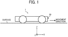
- FIG. 1 is a schematic view of a vehicle 1 mounted with a range sensor 20 such as a time-of-flight (TOF) sensor according to one or more example embodiments.
- the vehicle 1 is, for example, an unmanned transporter for transporting goods and others to a destination. Further, the vehicle 1 can be a manned vehicle depending on application fields.
- the three dimensional rectangular coordinate system "X, Y, Z" is defined by setting a direction perpendicular to a surface as Z-axis direction, and setting the forward direction of the vehicle 1 as +X direction.
- the vehicle 1 mounted with the range sensor 20 can be used in various fields such a factory, an inventory house or the like, but not limited to these.
- the range sensor 20 such as TOF sensor is, for example, disposed at the front end of the vehicle 1 to detect one or more objects existing at the +X direction side of the vehicle 1.
- an area or range detectable by the range sensor 20 is referred to a detection range.
- the range sensor 20 is described as an example of an
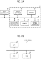
- the vehicle 1 includes, for example, a display 30, a monitoring controller 40, a memory 50, and a sound/alarm generator 60, which are electrically connected with each other via a bus 70 for communicating data.
- a monitoring apparatus 10 can be configured, for example, with the range sensor 20, the display 30, the monitoring controller 40, the memory 50 and the sound/alarm generator 60. Further, the monitoring apparatus 10 can be mounted to the vehicle 1. Further, the monitoring apparatus 10 can be electrically connected with a main controller 80 of the vehicle 1 via wire and/or wirelessly.
- the monitoring apparatus 10 can be devised as a sensor apparatus or a sensor system. When the monitoring apparatus 10 is devised as the sensor apparatus, the sensor apparatus including the range sensor 20, the display 30, the monitoring controller 40, the memory 50 and the sound/alarm generator 60 can be disposed on the vehicle 1.
- the entire or any one of the display 30, the monitoring controller 40, the memory 50 and the sound/alarm generator 60 configuring the sensor system may not be disposed on the vehicle 1 while the range sensor 20 is disposed on the vehicle 1.
- the entire or any one of the display 30, the monitoring controller 40, the memory 50 and the sound/alarm generator 60 configuring the sensor system may not be required to be disposed on the vehicle 1 but can be disposed separately from the vehicle 1.
- the monitoring controller 40 can be used as a controller to control the monitoring apparatus 10, and the monitoring controller 40 can be configured, for example, with a central processing unit (CPU) 110, a read only memory (ROM) 120 and a random access memory (RAM) 130 as illustrated in FIG. 2B .
- the main controller 80 is used as a controller to control the vehicle 1, and the main controller 80 can be also configured, for example, with the central processing unit (CPU) 110, the read only memory (ROM) 120 and the random access memory (RAM) 130 as illustrated in FIG. 2B .
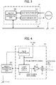
- the range sensor 20 includes, for example, a light emission unit 201, a light detection unit 202, and an object information acquisition unit 203, which are encased in a casing.
- the casing has a window, which may be attached with a translucent member such as glass, with which light emitted from the light emission unit 201 exits outside the range sensor 20 through the window, and light reflected from an object enters the light detection unit 202 through the window.
- the range sensor 20 can use various light for detecting the range to an object.
- the range sensor 20 can use infrared ray, visible range ray, and others depending on application fields.
- the object information acquisition unit 203 can be also configured, for example, with the central processing unit (CPU) 110, the read only memory (ROM) 120 and the random access memory (RAM) 130 as illustrated in FIG. 2B to communicate signals with other units to calculate range or distance information of objects. The calculation of range or distance information will be described later.
- CPU central processing unit
- ROM read only memory
- RAM random access memory
- the light emission unit 201 can be disposed at the - Z side of the light detection unit 202.
- the light emission unit 201 includes, for example, a light source 21, a coupling lens 22, a pulse controller 24, and a light source driver 25.
- the light source 21 can be turned ON and OFF under the control of the light source driver 25. As illustrated in FIG. 4 , the light source 21 can be disposed at a position to emit the light to the +X direction.
- a signal generated by the light source driver 25 used for driving the light source 21 is referred to a "light source drive signal" such as a pulse light.
- the coupling lens 22 can be disposed at the +X side of the light source 21. By passing the light emitted from the light source 21 through the coupling lens 22, the light can be converted to parallel light or slightly diffused light.
- the coupling lens 22 employs a flat-convex lens, which has a flat face at one side and a convex face at the opposite side of the coupling lens 22 as illustrated in FIG. 4 .
- the light passing through the coupling lens 22 can be used as the light emitted from the light emission unit 201.
- an optical coupling system including a plurality of optical elements having the same or similar capabilities can be used instead of the coupling lens 22, an optical coupling system including a plurality of optical elements having the same or similar capabilities can be used.
- the pulse controller 24 generates a signal (hereinafter, "pulse control signal") for controlling a pulse width "W" (i.e., emission time period) of the pulse light emitted from the light source 21 based on the range or distance information received from the object information acquisition unit 203.
- the pulse controller 24 can be also configured, for example, with the central processing unit (CPU) 110, the read only memory (ROM) 120 and the random access memory (RAM) 130 as illustrated in FIG. 2B .
- the pulse controller 24 transmits the pulse control signal to the light source driver 25 and the light detection unit 202.
- the pulse controller 24 when the pulse controller 24 outputs a pulse signal having a given pulse width to the light source driver 25 as the pulse control signal, a pulse light having the given pulse width is emitted from the light source 21 (see FIG. 5 ).
- the pulse controller 24 can be used as a pulse pattern controller to be described later in detail.
- the light source driver 25 generates the light source drive signal (see FIG. 6 ) based on the pulse control signal received from the pulse controller 24, and the light source driver 25 transmits the light source drive signal to the light source 21 and the object information acquisition unit 203.
- the light source 21 emits the pulse light having the pulse width instructed from the pulse controller 24.
- the pulse light emitted from the light source 21 may be referred to the "detection-use light.”
- the main controller 80 of the vehicle 1 transmits a request for starting acquisition of object information to the monitoring controller 40. Then, when the vehicle 1 reaches an intended position, the main controller 80 of the vehicle 1 transmits a request for ending acquisition of the object information to the monitoring controller 40.
- the monitoring controller 40 When the monitoring controller 40 receives the request for starting acquisition of the object information or the request for ending acquisition of the object information, the monitoring controller 40 transmits the request to the object information acquisition unit 203.
- the object information acquisition unit 203 When the object information acquisition unit 203 receives the request for starting acquisition of object information from the monitoring controller 40, the object information acquisition unit 203 transmits a request for starting a drive of the light source 21 to the light source driver 25, and a request for starting a pulse control of pulse light emitted from the light source 21 to the pulse controller 24.
- the object information acquisition unit 203 When the object information acquisition unit 203 receives the request for ending the acquisition of object information from the monitoring controller 40, the object information acquisition unit 203 transmits a request for ending the driving of the light source 21 to the light source driver 25, and a request for ending the pulse control of the pulse light emitted from the light source 21 to the pulse controller 24.
- the light emitted from the range sensor 20 is reflected from the object, and at least a part of the reflection light returns to the range sensor 20.
- the light reflected from the object and returned and received by the range sensor 20 may be referred to a "reflection light" from the object.
- the light detection unit 202 detects the reflection light from the object.
- the light detection unit 202 employs, for example, a TOF camera, which is an example of sensors to find the range to objects.
- the light detection unit 202 includes, for example, an image forming optical system 28, a light receiving unit 29, and an analog-digital (AD) converter 31.
- AD analog-digital
- the image forming optical system 28 is disposed at a position on the light path of the reflection light reflecting from the object to focus the light on the light receiving unit 29.
- the image forming optical system 28 is configured with one lens, but the image forming optical system 28 can be configured with two lenses and three or more lenses, or the image forming optical system 28 can employ a mirror unit.
- the light receiving unit 29 receives the reflection light reflected from the object via the image forming optical system 28.
- the light receiving unit 29 includes a light receiving element such as complementary metal oxide semiconductor (CMOS) image sensor.
- CMOS complementary metal oxide semiconductor
- the AD converter 31 converts analog signals received from the light receiving unit 29 to digital signals, and outputs the digital signals to the object information acquisition unit 203.
- the object information acquisition unit 203 calculates three dimensional information of the object such as two dimensional information of the object along a face perpendicular to the X-axis direction, and the range information of the object in the X-axis direction based on the output signals of the AD converter 31 and the light source drive signal. Since the basic operation of TOF camera and the acquisition method of three dimensional information are known, these are not described in this specification.
- the object information acquisition unit 203 outputs the acquired three dimensional information of the object to the pulse controller 24 and the monitoring controller 40.
- the range finding capability of the range sensor 20 is related to the pulse width "W" that is the emission time period of the pulse light. Specifically, the smaller the pulse width "W,” the higher the distance detection resolution and the higher the measurement precision. However, the smaller the pulse width "W,” the shorter the detectable distance due to the effect of aliasing of the pulse light.
- the aliasing means that reflection light returns at a time point that is longer than a cycle "T" of the pulse light. When the aliasing affects, it cannot determine when the reflection light is received by the range sensor 20. The aliasing effect does not occur if the reflection light is received by the range sensor 20 at a time point within two times of the pulse width "W" of the pulse light.
- the range information of the object is fed back to set the suitable pulse width "W" for the pulse light emitted from the light source 21 depending on the information of the range to the object.
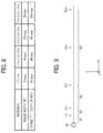
- the pulse controller 24 controls the pulse width "W" with a plurality patterns such as 50 nsec, 25 nsec, 10 nsec, and 5 nsec.
- the light-emission duty for each frequency is set, for example, 50 %, and it is configured to that the reflection light can be detected within a phase "2 ⁇ " of the pulse light. Therefore, in this example case, the cycle "T" of the pulse light can be respectively set with a plurality patterns such as 100 nsec, 50 nsec, 20 nsec, and 10 nsec.
- the maximum range that can be detected by using the reflection light reflected from the object and received by the light detection unit 202 at a time not exceeding the one cycle "T" of the pulse light can be set as follows.
- the detectable maximum range is set 1.5 m.
- the detectable maximum range is set 3 m.
- the detectable maximum range is set 25 nsec (and the cycle "T” is set 50 nsec when the duty is set 50 %).
- the detectable maximum range is set 7.5m.
- the detectable maximum range is set 15 m.
- the pulse controller 24 controls the pulse width "W” to 5 nsec when the distance “d” to the object is “d ⁇ 1 m,” controls the pulse width "W” to 10 nsec when the distance “d” to the object is “1 m ⁇ d ⁇ 2 m,” controls the pulse width "W” to 25 nsec when the distance “d” to the object is “2 m ⁇ d ⁇ 5 m,” and controls the pulse width "W” to 50 nsec when the distance "d” to the object is "5 m ⁇ d ⁇ 15 m.”
- the pulse controller 24 can set a smaller value for the pulse width "W” when the distance to the object becomes shorter, and can set a greater value for the pulse width "W” when the distance to the object becomes farther.
- a range that the distance of the object from the range sensor 20 is 1 m or less (d ⁇ 1 m) is referred to a first range "R1," a range that the distance of the object from the range sensor 20 is greater than 1m and 2 m or less (1m ⁇ d ⁇ 2 m) is referred to a second range "R2," a range that the distance of the object from the range sensor 20 is greater than 2 m and 5 m or less (2 m ⁇ d ⁇ 5 m) is referred to a third range "R3,” and a range that the distance of the object from the range sensor 20 is greater than 5 m and 15 m or less (5 m ⁇ d ⁇ 15 m) is referred to a fourth range "R4".
- the pulse width "W” corresponding to the first range “R1” is set, for example, 5 nsec
- the pulse width "W” corresponding to the second range “R2” is set, for example, 10 nsec
- the pulse width "W” corresponding to the third range “R3” is set, for example, 25 nsec
- the pulse width "W” corresponding to the fourth range “R4" is set, for example, 50 nsec.
- the first to fourth ranges "R1" to “R4" may be collectively referred to the "range information.”
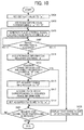
- FIG. 10 is a flowchart illustrating the steps of a process or algorithm performable by the pulse controller 24, in which it is assumed that an object exists at +X side of the range sensor 20.
- a default value is set to a variable "w" where the pulse width of the pulse control signal can be stored. For example, 50 nsec is set as a default value. Further, if another range finding apparatus is disposed, the default value can be determined based on a measurement result by another range finding apparatus. Further, if the range or distance to the object is already known, the pulse width corresponding to the already known distance can be set as the default value. At step S401, any value that is suitable for the range detection process can be set to the variable "w" as the default value as required.
- the range information corresponding the pulse width stored in the variable "w” is set to a variable "R" to store the range information corresponding to the pulse width of the pulse control signal. For example, if the default value of the variable "w” is set with 50 nsec at step S401, the variable “R” is set with "R4" at step S403 based on the information indicated in FIGs. 8 and 9 .
- the pulse controller 24 generates a pulse control signal having the pulse width stored in the variable "w.” Then, the pulse controller 24 transmits the pulse control signal to the light source driver 25 and the light detection unit 202. Then, the light source driver 25 drives the light source 21 to emit the pulse light having the pulse width stored in the variable "w.”
- the pulse controller 24 determines whether the pulse controller 24 receives or acquires the range information from the object information acquisition unit 203. If the pulse controller 24 does not yet receive the range information (step S407: NO(1)), the pulse controller 24 waits to receive the range information. If the pulse controller 24 receives the range information (step S407: YES), the sequence proceeds to step S411.
- the pulse controller 24 calculates the range information corresponding to the distance "d” acquired at step S407. For example, if the distance "d” acquired at step S407 is “10 m,” the pulse controller 24 acquires the range information "R4,” and if the distance "d” acquired at step S407 is "5 m,” the pulse controller 24 acquires the range information "R3.”
- step S413 the pulse controller 24 determines whether the acquired range information and the range information stored in the variable "R" are the same information. If the acquired range information and the range information stored in the variable "R" are not the same information (step S413: NO), the sequence proceeds to step S415.
- the pulse controller 24 sets the acquired range information to the variable "R,” in which the pulse controller 24 updates the contents of the variable "R".
- the pulse controller 24 calculates a pulse width corresponding to the acquired range information. For example, if the acquired range information is "R3,” the pulse controller 24 acquires 25 nsec, and if the acquired range information is "R2,” the pulse controller 24 acquires 50 nsec.
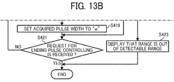
- the pulse controller 24 sets the acquired pulse width to the variable "w,” in which the pulse controller 24 updates the contents of the variable "w.”
- step S421 the pulse controller 24 determines whether a request for ending the pulse control is received. If the request for ending the pulse control is not received (step S421: NO), the sequence returns to step S405.
- step S407 NO(2)
- the sequence proceeds to step S423. Further, if the range information acquired at step S407 is determined abnormal such as the acquired range information exceeds the maximum detectable distance, the sequence also proceeds to step S423.
- the pulse controller 24 determines that the range information is not acquired due to some reasons. In this case, for example, the pulse controller 24 instructs to display that the range is out of the detectable range, and ends the pulse control processing.
- step S413 YES
- the sequence proceeds to step S421, in which the contents of the variable "w" is not updated.
- step S421 YES
- the pulse controller 24 ends the pulse controlling process.
- the monitoring controller 40 receives three dimensional information of the object from the object information acquisition unit 203, the monitoring controller 40 can refer to a plurality of three dimensional information that is acquired most recently, and then the monitoring controller 40 calculates movement information of the object such as relative movement direction and relative movement velocity of the object with respect to the vehicle 1. Then, the monitoring controller 40 displays the three dimensional information and the movement information of the object with respect to the vehicle 1 on the display 30. Further, the monitoring controller 40 outputs the three dimensional information and the movement information of the object with respect to the vehicle 1 to the main controller 80 of the vehicle 1.
- the main controller 80 of the vehicle 1 can control a position of the vehicle 1 relative to the object based on the three dimensional information and the movement information of the object with respect to the vehicle 1 received from the monitoring controller 40.
- the monitoring controller 40 can determine whether a dangerous event such as a collision to other objects is expected to occur based on the three dimensional information and the movement information of the object with respect to the vehicle 1. If the monitoring controller 40 determines that the dangerous event is expected to occur, the monitoring controller 40 reports danger-expecting information to the main controller 80 of the vehicle 1, and the sound/alarm generator 60.
- the main controller 80 of the vehicle 1 receives the danger-expecting information from the monitoring controller 40, the main controller 80 can perform an evasive action, which can be set in advance.
- the sound/alarm generator 60 includes, for example, an audio synthesizing unit 61, an alarm signal generator 62, and a speaker 63.
- the audio synthesizing unit 61 stores a plurality of audio or sound data.
- the audio synthesizing unit 61 selects audio data corresponding to the received danger-expecting information, and outputs the corresponding audio data to the speaker 63, and the speaker 63 outputs audio corresponding to the audio data.
- the alarm signal generator 62 When the alarm signal generator 62 receives the danger-expecting information from the monitoring controller 40, the alarm signal generator 62 generates a corresponding alarm signal, and outputs the alarm signal to the speaker 63, and then the speaker 63 outputs audio corresponding to the alarm signal.
- the light detection unit 202 can be used as the light receiver of the range sensor 20, and the object information acquisition unit 203 can be used as the range information acquisition unit of the range sensor 20.
- the pulse controller 24 can perform a range finding method of one or more example embodiments of the present invention.
- the range sensor 20 includes, for example, the light emission unit 201, the light detection unit 202, and the object information acquisition unit 203.
- the light emission unit 201 includes, for example, the light source 21, the coupling lens 22, the pulse controller 24, and the light source driver 25.
- the object information acquisition unit 203 calculates the distance or range to the object using, for example, the TOF calculation method. Specifically, the object information acquisition unit 203 calculates the range to the object based on a time difference of one time point when the pulse light is emitted from the light source 21 and another time point when the light reflected from the object is detected by the light detection unit 202, and the speed of the pulse light.
- the pulse controller 24 can control a pulse width of the pulse light to be emitted from the light source 21.
- the object information acquisition unit 203 uses one pulse of the pulse light when the range to the object is computed. Therefore, the range information can be calculated without a complex computation and without degrading a real time computation. As to conventional methods, the complex computation may be required and/or the real time computation may not be performed.
- the pulse controller 24 sets a smaller pulse width for the pulse light (i.e., emission time period), and when the distance or range to the object from the range sensor 20 becomes farther, the pulse controller 24 sets a greater pulse width for the pulse light (i.e., emission time period). Therefore, the pulse light can be emitted from the light source 21 with a suitable pulse width depending on the range to the object, with which the detection precision can be enhanced, and the detection range can be enhanced.
- the monitoring apparatus 10 includes the range sensor 20, the monitoring can be performed with higher precision.
- the pulse controller 24 controls the pulse width of the pulse light emitted from the light source 21 based on one range information acquired most recently at one time point, but not limited hereto.
- the pulse controller 24 can predict next range information based on a plurality of range information acquired most recently, and control the pulse width of the pulse light based on a prediction result.
- FIG. 12 is a flowchart illustrating the steps of a process of pulse controlling using the prediction result based on the plurality of range information.
- the plurality of range information acquired most recently can be acquired by detecting range information at a plurality of most recent time points.
- the flowchart of FIG. 12 includes steps S408_1 and S408_2 between steps S407 and S409, which is different from the flowchart of FIG. 10 .
- the range information transmitted from the object information acquisition unit 203 is stored in a memory such as the memory 50, in which the memory stores a plurality of range information acquired in time series.
- the pulse controller 24 calculates the relative movement velocity and acceleration of the object with respect to the vehicle 1 based on the plurality of range information stored in the memory most recently, and predicts next range information, in which a predicted next range information is referred to the distance "d" in FIG. 12 .
- the pulse controller 24 determines whether abnormality occurs to the range sensor 20 based on the prediction result (step S408_3).
- the abnormality means that the detected range has irregularities such as a first range detected for one frame and a second range detected for the next frame have a discrepancy greater than a pre-set threshold, in which a change level of the detected range is determined. If the abnormality of the range sensor 20 is detected (step S408_3: YES), the pulse controller 24 outputs an alarm signal (step S408_4). Specifically, the pulse controller 24 outputs the alarm signal to the monitoring controller 40 via the object information acquisition unit 203.
- the monitoring controller 40 When the monitoring controller 40 receives the alarm signal, the monitoring controller 40 reports the abnormality of the range sensor 20 to the main controller 80 of the vehicle 1, and the sound/alarm generator 60.
- the sound/alarm generator 60 receives the abnormality of the range sensor 20 from the monitoring controller 40, the sound/alarm generator 60 outputs a given audio such as an alarm sound.
- the main controller 80 of the vehicle 1 receives the abnormality of the range sensor 20 from the monitoring controller 40
- the main controller 80 performs a given process set for the abnormality situation in advance.
- the pulse controller 24 sets the pulse width "W" of the pulse light, which is the emission time period, to 50 nsec, 25 nsec, 10 nsec, and 5 nsec, but not limited hereto.
- the pulse width "W" of the pulse light can be set with any values as required.
- the pulse controller 24 sets the pulse width with four types of pulse width but not limited hereto.
- the pulse controller 24 can set the pulse width with any values such as six types of the pulse width as required.
- the light-emission duty is set 50 %, but not limited hereto.
- the light-emission duty can be set with any values such as 30 % as required
- the maximum detectable range of the object is set 15 m, but not limited hereto.
- the maximum detectable range of the object can be set with any values as required.
- the light receiving unit 29 acquires the three dimensional information of the object, but not limited hereto. For example, it may be sufficient if the light receiving unit 29 can acquire information of at least distance or range to the object.
- a part of the processing performed by the object information acquisition unit 203 can be performed by the monitoring controller 40, or a part of the processing performed by the monitoring controller 40 can be performed by the object information acquisition unit 203.
- the AD converter 31 can be integrated with the light receiving unit 29, or can be integrated with the object information acquisition unit 203.
- a part of the processing performed by the object information acquisition unit 203 can be performed by the light receiving unit 29, or a part of the processing performed by the light receiving unit 29 can be performed by the object information acquisition unit 203.
- the monitoring apparatus 10 includes one range sensor, but not limited hereto.
- the monitoring apparatus 10 can include a plurality of the range sensors such as TOF sensors depending on sizes of vehicles and a monitoring range.
- the range sensor 20 is used for the monitoring apparatus 10 that monitors the travel direction of the vehicle, but not limited hereto.
- the range sensor 20 can be used for monitoring apparatuses that monitor the rear and/or sides of the vehicle.
- the range sensor 20 can be applied to the sensor systems or sensor apparatuses not mounted to the vehicles, in which the monitoring controller 40 can output alarm information matched to application fields of the sensor systems or sensor apparatuses.
- the range sensor 20 and the sensor system used for the vehicle 1 may include a plurality of controllers to perform the above described processing as above described with reference to drawings but not limited hereto.
- the range sensor 20 and the sensor system used for the vehicle 1 may include at least one controller that can perform the above described processing.
- the range sensor 20 can be applied to various apparatuses other than the sensor system and sensor apparatuses.
- the range sensor 20 can be applied to a range finding apparatus and a shape measurement apparatus.
- the range information can be calculated without a complex computation and without degrading a real time computation, and thereby the detection precision can be enhanced and the detection range can be enhanced.
- the present invention can be implemented in any convenient form, for example using dedicated hardware, or a mixture of dedicated hardware and software.
- the present invention may be implemented as computer software implemented by one or more networked processing apparatuses.
- the network can comprise any conventional terrestrial or wireless communications network, such as the Internet.
- the processing apparatuses can compromise any suitably programmed apparatuses such as a general purpose computer, personal digital assistant, mobile telephone (such as a WAP or 3G-compliant phone) and so on.
Landscapes
- Physics & Mathematics (AREA)
- Engineering & Computer Science (AREA)
- Electromagnetism (AREA)
- Computer Networks & Wireless Communication (AREA)
- General Physics & Mathematics (AREA)
- Radar, Positioning & Navigation (AREA)
- Remote Sensing (AREA)
- Optical Radar Systems And Details Thereof (AREA)
- Measurement Of Optical Distance (AREA)
Applications Claiming Priority (1)
| Application Number | Priority Date | Filing Date | Title |
|---|---|---|---|
| JP2015122820A JP2017009339A (ja) | 2015-06-18 | 2015-06-18 | センサ、センシング装置及び距離計測方法 |
Publications (1)
| Publication Number | Publication Date |
|---|---|
| EP3112902A1 true EP3112902A1 (de) | 2017-01-04 |
Family
ID=56120973
Family Applications (1)
| Application Number | Title | Priority Date | Filing Date |
|---|---|---|---|
| EP16174229.1A Withdrawn EP3112902A1 (de) | 2015-06-18 | 2016-06-13 | Sensor, sensorsystem und verfahren zum auffinden eines bereichs |
Country Status (3)
| Country | Link |
|---|---|
| US (1) | US20160370460A1 (de) |
| EP (1) | EP3112902A1 (de) |
| JP (1) | JP2017009339A (de) |
Families Citing this family (10)
| Publication number | Priority date | Publication date | Assignee | Title |
|---|---|---|---|---|
| JP2017133853A (ja) | 2016-01-25 | 2017-08-03 | 株式会社リコー | 測距装置 |
| US10481263B2 (en) | 2016-03-10 | 2019-11-19 | Ricoh Company, Ltd. | Range finding apparatus, moveable apparatus, robot, three dimensional measurement apparatus, method of measuring three dimensional information, and storage medium |
| JP6855746B2 (ja) | 2016-10-18 | 2021-04-07 | 株式会社リコー | 測距装置、監視カメラ、3次元計測装置、移動体、ロボット及び測距方法 |
| JP6848364B2 (ja) | 2016-11-10 | 2021-03-24 | 株式会社リコー | 測距装置、移動体、ロボット、3次元計測装置、監視カメラ及び測距方法 |
| JP6988071B2 (ja) | 2016-11-16 | 2022-01-05 | 株式会社リコー | 距離測定装置及び距離測定方法 |
| US10754033B2 (en) * | 2017-06-30 | 2020-08-25 | Waymo Llc | Light detection and ranging (LIDAR) device range aliasing resilience by multiple hypotheses |
| US10627492B2 (en) | 2017-08-01 | 2020-04-21 | Waymo Llc | Use of extended detection periods for range aliasing detection and mitigation in a light detection and ranging (LIDAR) system |
| JP6933045B2 (ja) | 2017-08-18 | 2021-09-08 | 株式会社リコー | 物体検出装置、センシング装置、移動体装置及び物体検出方法 |
| US11802943B2 (en) * | 2017-11-15 | 2023-10-31 | OPSYS Tech Ltd. | Noise adaptive solid-state LIDAR system |
| JP2020153715A (ja) * | 2019-03-18 | 2020-09-24 | 株式会社リコー | 測距装置および測距方法 |
Citations (3)
| Publication number | Priority date | Publication date | Assignee | Title |
|---|---|---|---|---|
| US20130235366A1 (en) * | 2012-03-07 | 2013-09-12 | Vectronix Ag | Distance measuring device |
| JP2013538342A (ja) | 2010-07-21 | 2013-10-10 | マイクロソフト コーポレーション | 階層的な飛行時間(tof)システムのディエリアシング方法およびシステム |
| JP2015501927A (ja) | 2012-01-10 | 2015-01-19 | ソフトキネティック センサー エヌブイ | タイムオブフライト信号の処理における又はこれに関する改良 |
Family Cites Families (15)
| Publication number | Priority date | Publication date | Assignee | Title |
|---|---|---|---|---|
| DE2834660A1 (de) * | 1978-08-08 | 1980-02-21 | Honeywell Gmbh | Laser-entfernungsmesser |
| JPH07134178A (ja) * | 1993-11-12 | 1995-05-23 | Omron Corp | レーザ光を用いた車載用距離測定装置 |
| JPH07260937A (ja) * | 1994-03-22 | 1995-10-13 | Nikon Corp | 距離測定装置 |
| US5717401A (en) * | 1995-09-01 | 1998-02-10 | Litton Systems, Inc. | Active recognition system with optical signal processing |
| JP2004157061A (ja) * | 2002-11-08 | 2004-06-03 | Nikon-Trimble Co Ltd | 距離測定装置 |
| US7323670B2 (en) * | 2004-03-16 | 2008-01-29 | Leica Geosystems Hds Llc | Laser operation for survey instruments |
| JP4525253B2 (ja) * | 2004-08-30 | 2010-08-18 | オムロン株式会社 | 光センサおよび測距方法 |
| DE102005054135A1 (de) * | 2005-11-14 | 2007-05-16 | Bosch Gmbh Robert | Verfahren zur Umfelderfassung |
| US7936448B2 (en) * | 2006-01-27 | 2011-05-03 | Lightwire Inc. | LIDAR system utilizing SOI-based opto-electronic components |
| JP2010107448A (ja) * | 2008-10-31 | 2010-05-13 | Toyota Motor Corp | 距離測定装置 |
| US10571571B2 (en) * | 2010-11-12 | 2020-02-25 | Texas Instruments Incorporated | Method and apparatus for controlling time of flight confidence map based depth noise and depth coverage range |
| JP2012159330A (ja) * | 2011-01-31 | 2012-08-23 | Sanyo Electric Co Ltd | レーザレーダ |
| US20130278441A1 (en) * | 2012-04-24 | 2013-10-24 | Zetta Research and Development, LLC - ForC Series | Vehicle proxying |
| EP2677340A1 (de) * | 2012-06-18 | 2013-12-25 | Hexagon Technology Center GmbH | Distanzmessverfahren mit dynamischer Pulsweitenanpassung |
| KR20150095033A (ko) * | 2014-02-12 | 2015-08-20 | 한국전자통신연구원 | 레이저 레이더 장치 및 그것의 영상 획득 방법 |
-
2015
- 2015-06-18 JP JP2015122820A patent/JP2017009339A/ja active Pending
-
2016
- 2016-06-13 US US15/180,560 patent/US20160370460A1/en not_active Abandoned
- 2016-06-13 EP EP16174229.1A patent/EP3112902A1/de not_active Withdrawn
Patent Citations (3)
| Publication number | Priority date | Publication date | Assignee | Title |
|---|---|---|---|---|
| JP2013538342A (ja) | 2010-07-21 | 2013-10-10 | マイクロソフト コーポレーション | 階層的な飛行時間(tof)システムのディエリアシング方法およびシステム |
| JP2015501927A (ja) | 2012-01-10 | 2015-01-19 | ソフトキネティック センサー エヌブイ | タイムオブフライト信号の処理における又はこれに関する改良 |
| US20130235366A1 (en) * | 2012-03-07 | 2013-09-12 | Vectronix Ag | Distance measuring device |
Also Published As
| Publication number | Publication date |
|---|---|
| JP2017009339A (ja) | 2017-01-12 |
| US20160370460A1 (en) | 2016-12-22 |
Similar Documents
| Publication | Publication Date | Title |
|---|---|---|
| EP3112902A1 (de) | Sensor, sensorsystem und verfahren zum auffinden eines bereichs | |
| US10481263B2 (en) | Range finding apparatus, moveable apparatus, robot, three dimensional measurement apparatus, method of measuring three dimensional information, and storage medium | |
| US20190286145A1 (en) | Method and Apparatus for Dynamic Obstacle Avoidance by Mobile Robots | |
| JP6922187B2 (ja) | 測距装置、監視カメラ、3次元計測装置、移動体、ロボット及び光源駆動条件設定方法 | |
| US10532909B2 (en) | Elevator passenger tracking control and call cancellation system | |
| US6697147B2 (en) | Position measurement apparatus and method using laser | |
| KR101521356B1 (ko) | 거리 측정 장치, 거리 측정 방법 및 컴퓨터 판독 가능한 기억 매체 | |
| JP6855746B2 (ja) | 測距装置、監視カメラ、3次元計測装置、移動体、ロボット及び測距方法 | |
| US20200356094A1 (en) | Methods and systems for machine state related visual feedback in a robotic device | |
| CN103443838B (zh) | 物体识别装置 | |
| US20230090576A1 (en) | Dynamic control and configuration of autonomous navigation systems | |
| US20250035787A1 (en) | Systems And Methods For A Configurable Sensor System | |
| EP4671906A1 (de) | Verfahren und vorrichtung zur trajektorieneinstellung einer autonomen mobilen vorrichtung | |
| CN108430851B (zh) | 夜间图像显示装置及其图像处理方法 | |
| US20230384444A1 (en) | Autonomous movement device and autonomous movement system | |
| JP2017075881A (ja) | 物体認識統合装置および物体認識統合方法 | |
| CN115201786A (zh) | 一种激光雷达的同步控制装置及方法 | |
| US20230078063A1 (en) | Distance measurement device and distance measurement system | |
| CN110497861B (zh) | 传感器系统及检查方法 | |
| CN110174679B (zh) | 用于光学测距的方法和装置 | |
| WO2019127977A1 (zh) | 多线激光测距装置以及机器人 | |
| EP3754377B1 (de) | Steuerungsvorrichtung, bestrahlungssystem, steuerungsverfahren und programm | |
| JP6736682B2 (ja) | センサ装置、センシング方法、プログラム及び記憶媒体 | |
| WO2023079944A1 (ja) | 制御装置、制御方法、制御プログラム | |
| US20220311923A1 (en) | System, position detecting device, position detecting method, and program |
Legal Events
| Date | Code | Title | Description |
|---|---|---|---|
| PUAI | Public reference made under article 153(3) epc to a published international application that has entered the european phase |
Free format text: ORIGINAL CODE: 0009012 |
|
| STAA | Information on the status of an ep patent application or granted ep patent |
Free format text: STATUS: REQUEST FOR EXAMINATION WAS MADE |
|
| 17P | Request for examination filed |
Effective date: 20160613 |
|
| AK | Designated contracting states |
Kind code of ref document: A1 Designated state(s): AL AT BE BG CH CY CZ DE DK EE ES FI FR GB GR HR HU IE IS IT LI LT LU LV MC MK MT NL NO PL PT RO RS SE SI SK SM TR |
|
| AX | Request for extension of the european patent |
Extension state: BA ME |
|
| STAA | Information on the status of an ep patent application or granted ep patent |
Free format text: STATUS: EXAMINATION IS IN PROGRESS |
|
| 17Q | First examination report despatched |
Effective date: 20181011 |
|
| STAA | Information on the status of an ep patent application or granted ep patent |
Free format text: STATUS: THE APPLICATION HAS BEEN WITHDRAWN |
|
| 18W | Application withdrawn |
Effective date: 20190111 |