EP3112191A1 - Reifendrucksensoranordnungen mit einem reifendrucksensor zur anpassung an ein überdruckentlastungsventil in einem flugzeugradsystem - Google Patents
Reifendrucksensoranordnungen mit einem reifendrucksensor zur anpassung an ein überdruckentlastungsventil in einem flugzeugradsystem Download PDFInfo
- Publication number
- EP3112191A1 EP3112191A1 EP16177563.0A EP16177563A EP3112191A1 EP 3112191 A1 EP3112191 A1 EP 3112191A1 EP 16177563 A EP16177563 A EP 16177563A EP 3112191 A1 EP3112191 A1 EP 3112191A1
- Authority
- EP
- European Patent Office
- Prior art keywords
- pressure sensor
- tire pressure
- tire
- sensor
- inflation
- Prior art date
- Legal status (The legal status is an assumption and is not a legal conclusion. Google has not performed a legal analysis and makes no representation as to the accuracy of the status listed.)
- Pending
Links
- 230000000712 assembly Effects 0.000 title description 6
- 238000000429 assembly Methods 0.000 title description 6
- 230000013011 mating Effects 0.000 title description 4
- 239000012530 fluid Substances 0.000 claims abstract description 20
- 238000004891 communication Methods 0.000 claims abstract description 17
- 230000000295 complement effect Effects 0.000 claims description 9
- 230000008878 coupling Effects 0.000 claims description 3
- 238000010168 coupling process Methods 0.000 claims description 3
- 238000005859 coupling reaction Methods 0.000 claims description 3
- 238000000034 method Methods 0.000 description 11
- 230000008901 benefit Effects 0.000 description 6
- 238000010894 electron beam technology Methods 0.000 description 4
- 239000000463 material Substances 0.000 description 4
- 230000008018 melting Effects 0.000 description 4
- 238000002844 melting Methods 0.000 description 4
- 239000002184 metal Substances 0.000 description 4
- 238000010146 3D printing Methods 0.000 description 2
- 229910001369 Brass Inorganic materials 0.000 description 2
- 229910000831 Steel Inorganic materials 0.000 description 2
- 239000000654 additive Substances 0.000 description 2
- 230000000996 additive effect Effects 0.000 description 2
- 238000000149 argon plasma sintering Methods 0.000 description 2
- 239000010951 brass Substances 0.000 description 2
- 238000005266 casting Methods 0.000 description 2
- 229910010293 ceramic material Inorganic materials 0.000 description 2
- 239000002131 composite material Substances 0.000 description 2
- 230000008021 deposition Effects 0.000 description 2
- 238000010100 freeform fabrication Methods 0.000 description 2
- 238000003754 machining Methods 0.000 description 2
- 238000004519 manufacturing process Methods 0.000 description 2
- 238000012544 monitoring process Methods 0.000 description 2
- 238000012545 processing Methods 0.000 description 2
- 230000000717 retained effect Effects 0.000 description 2
- 238000000110 selective laser sintering Methods 0.000 description 2
- 238000005245 sintering Methods 0.000 description 2
- 239000010959 steel Substances 0.000 description 2
- 238000003466 welding Methods 0.000 description 2
- 238000010586 diagram Methods 0.000 description 1
- 238000010297 mechanical methods and process Methods 0.000 description 1
- 238000000926 separation method Methods 0.000 description 1
- 239000012207 thread-locking agent Substances 0.000 description 1
Images


Classifications
-
- B—PERFORMING OPERATIONS; TRANSPORTING
- B60—VEHICLES IN GENERAL
- B60C—VEHICLE TYRES; TYRE INFLATION; TYRE CHANGING; CONNECTING VALVES TO INFLATABLE ELASTIC BODIES IN GENERAL; DEVICES OR ARRANGEMENTS RELATED TO TYRES
- B60C23/00—Devices for measuring, signalling, controlling, or distributing tyre pressure or temperature, specially adapted for mounting on vehicles; Arrangement of tyre inflating devices on vehicles, e.g. of pumps or of tanks; Tyre cooling arrangements
- B60C23/02—Signalling devices actuated by tyre pressure
- B60C23/04—Signalling devices actuated by tyre pressure mounted on the wheel or tyre
- B60C23/0491—Constructional details of means for attaching the control device
- B60C23/0498—Constructional details of means for attaching the control device for rim attachments
-
- B—PERFORMING OPERATIONS; TRANSPORTING
- B60—VEHICLES IN GENERAL
- B60C—VEHICLE TYRES; TYRE INFLATION; TYRE CHANGING; CONNECTING VALVES TO INFLATABLE ELASTIC BODIES IN GENERAL; DEVICES OR ARRANGEMENTS RELATED TO TYRES
- B60C23/00—Devices for measuring, signalling, controlling, or distributing tyre pressure or temperature, specially adapted for mounting on vehicles; Arrangement of tyre inflating devices on vehicles, e.g. of pumps or of tanks; Tyre cooling arrangements
- B60C23/02—Signalling devices actuated by tyre pressure
- B60C23/04—Signalling devices actuated by tyre pressure mounted on the wheel or tyre
- B60C23/0491—Constructional details of means for attaching the control device
- B60C23/0496—Valve stem attachments positioned outside of the tyre chamber
-
- B—PERFORMING OPERATIONS; TRANSPORTING
- B60—VEHICLES IN GENERAL
- B60C—VEHICLE TYRES; TYRE INFLATION; TYRE CHANGING; CONNECTING VALVES TO INFLATABLE ELASTIC BODIES IN GENERAL; DEVICES OR ARRANGEMENTS RELATED TO TYRES
- B60C29/00—Arrangements of tyre-inflating valves to tyres or rims; Accessories for tyre-inflating valves, not otherwise provided for
- B60C29/06—Accessories for tyre-inflating valves, e.g. housings, guards, covers for valve caps, locks, not otherwise provided for
- B60C29/068—Pressure relief devices, i.e. safety devices for overpressure
-
- F—MECHANICAL ENGINEERING; LIGHTING; HEATING; WEAPONS; BLASTING
- F16—ENGINEERING ELEMENTS AND UNITS; GENERAL MEASURES FOR PRODUCING AND MAINTAINING EFFECTIVE FUNCTIONING OF MACHINES OR INSTALLATIONS; THERMAL INSULATION IN GENERAL
- F16K—VALVES; TAPS; COCKS; ACTUATING-FLOATS; DEVICES FOR VENTING OR AERATING
- F16K15/00—Check valves
- F16K15/20—Check valves specially designed for inflatable bodies, e.g. tyres
- F16K15/207—Check valves specially designed for inflatable bodies, e.g. tyres and combined with other valves, e.g. safety valves
-
- F—MECHANICAL ENGINEERING; LIGHTING; HEATING; WEAPONS; BLASTING
- F16—ENGINEERING ELEMENTS AND UNITS; GENERAL MEASURES FOR PRODUCING AND MAINTAINING EFFECTIVE FUNCTIONING OF MACHINES OR INSTALLATIONS; THERMAL INSULATION IN GENERAL
- F16K—VALVES; TAPS; COCKS; ACTUATING-FLOATS; DEVICES FOR VENTING OR AERATING
- F16K17/00—Safety valves; Equalising valves, e.g. pressure relief valves
- F16K17/02—Safety valves; Equalising valves, e.g. pressure relief valves opening on surplus pressure on one side; closing on insufficient pressure on one side
- F16K17/14—Safety valves; Equalising valves, e.g. pressure relief valves opening on surplus pressure on one side; closing on insufficient pressure on one side with fracturing member
- F16K17/16—Safety valves; Equalising valves, e.g. pressure relief valves opening on surplus pressure on one side; closing on insufficient pressure on one side with fracturing member with fracturing diaphragm ; Rupture discs
-
- B—PERFORMING OPERATIONS; TRANSPORTING
- B60—VEHICLES IN GENERAL
- B60C—VEHICLE TYRES; TYRE INFLATION; TYRE CHANGING; CONNECTING VALVES TO INFLATABLE ELASTIC BODIES IN GENERAL; DEVICES OR ARRANGEMENTS RELATED TO TYRES
- B60C23/00—Devices for measuring, signalling, controlling, or distributing tyre pressure or temperature, specially adapted for mounting on vehicles; Arrangement of tyre inflating devices on vehicles, e.g. of pumps or of tanks; Tyre cooling arrangements
- B60C23/02—Signalling devices actuated by tyre pressure
- B60C23/04—Signalling devices actuated by tyre pressure mounted on the wheel or tyre
- B60C23/0408—Signalling devices actuated by tyre pressure mounted on the wheel or tyre transmitting the signals by non-mechanical means from the wheel or tyre to a vehicle body mounted receiver
- B60C23/0484—Detecting an ongoing tyre inflation
-
- B—PERFORMING OPERATIONS; TRANSPORTING
- B60—VEHICLES IN GENERAL
- B60C—VEHICLE TYRES; TYRE INFLATION; TYRE CHANGING; CONNECTING VALVES TO INFLATABLE ELASTIC BODIES IN GENERAL; DEVICES OR ARRANGEMENTS RELATED TO TYRES
- B60C23/00—Devices for measuring, signalling, controlling, or distributing tyre pressure or temperature, specially adapted for mounting on vehicles; Arrangement of tyre inflating devices on vehicles, e.g. of pumps or of tanks; Tyre cooling arrangements
- B60C23/02—Signalling devices actuated by tyre pressure
- B60C23/04—Signalling devices actuated by tyre pressure mounted on the wheel or tyre
- B60C23/0491—Constructional details of means for attaching the control device
- B60C23/0494—Valve stem attachments positioned inside the tyre chamber
Definitions
- the present disclosure relates generally to tire pressure sensors and, more specifically, to tire pressure sensor assemblies including a tire pressure sensor for mating with an over-inflation pressure relief valve in an aircraft wheel system.
- a tire pressure sensor is provided in accordance with various embodiments.
- the tire pressure sensor comprises a sensor housing having a first engagement portion defining an opening.
- a pressure sensing element is within the sensor housing and is in fluid communication with the opening of the sensor housing.
- the tire pressure sensor is configured to engage and be in fluid communication with an over-inflation pressure relief valve.
- the over-inflation relief valve is engagable in a wheel of an aircraft wheel assembly.
- the tire pressure sensor is also disengagable from the over-inflation pressure relief valve.
- a tire pressure sensor assembly comprises an over-inflation pressure relief valve a tire pressure sensor engaged with, and configured to be in fluid communication with, the over-inflation pressure relief valve and disengagable therefrom.
- the over-inflation pressure relief valve is engagable in a wheel of an aircraft wheel assembly.
- the tire pressure sensor comprises a sensor housing having a first engagement portion defining an opening and a pressure sensing element within the sensor housing and in fluid communication with the opening of the sensor housing.
- the aircraft wheel system comprises a wheel having a sensor receptacle.
- An over-inflation pressure relief valve within pressure relief housing has a stem configured to mate with the sensor receptacle and defines a tire inflation gas entry opening.
- the over-inflation pressure relief valve comprises a frangible disk configured to rupture at a predetermined pressure.
- a tire pressure sensor is engageable with and disengagable from the over-inflation pressure relief valve. The tire pressure sensor is in fluid communication with the over-inflation pressure relief valve.
- the present disclosure describes various embodiments of tire pressure sensor assemblies including a tire pressure sensor for mating with an over-inflation pressure relief valve for use with aircraft wheels, as well as aircraft wheel systems.
- Various embodiments may be utilized in new aircraft designs, or retrofit to existing aircraft.
- Various embodiments permit easy replacement of a failed tire pressure sensor or failed over-inflation (OI) pressure relief valve, without having to sacrifice a one-piece unit comprising a combination tire pressure sensor and over-inflation pressure relief valve.
- OEM over-inflation
- wheel system 100 comprises a wheel 102 having a valve receptacle 104.
- Valve receptacle 104 may, for example, receive an over-inflation pressure relief valve 106.
- Valve receptacle 104 may have the same size, shape, and configuration as conventional valve receptacles of conventional aircraft wheel systems.
- valve receptacle 104 may comprise a threaded portion configured to mate with a complementary threaded portion of a sensor and/or valve.
- any configuration of valve receptacle 104 is within the scope of the present disclosure.
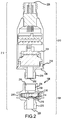
- a tire pressure sensor assembly 212 comprises an over-inflation pressure-relief valve 106 ( FIG. 3 ) engaged with a tire pressure sensor 210.
- the tire pressure sensor 210 is configured to engage and be in fluid communication with the over-inflation pressure relief valve.
- the tire pressure sensor is also disengagable from the over-inflation pressure-relief valve 106.
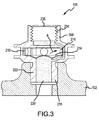
- the over-inflation pressure relief valve 106 may comprise a pressure relief housing 208 in accordance with various embodiments.
- pressure relief housing 208 comprises a metal, such as brass or steel.
- pressure relief housing 208 comprises a composite material.
- pressure relief housing 208 comprises a ceramic material.
- Pressure relief housing 208 may be manufactured using additive manufacturing techniques, such as, for example, fused deposition modeling, polyjet 3D printing, electron beam freeform fabrication, direct metal laser sintering, electron-beam melting, selective laser melting, selective heat sintering, selective laser sintering, stereolithography, multiphoton photopolymerization, and/or digital light processing. Pressure relief housing 208 may also be manufactured using "conventional" techniques such as, for example, casting, machining, welding, or bonding. Any material and configuration of pressure relief housing 208 capable of withstanding pressure associated with inflated aircraft tires (e.g., 30 psi to 350 psi) is within the scope of the present disclosure.
- Pressure relief housing 208 may comprise, for example, a stem 218.
- Stem 218 may be configured to interact with and be retained by valve receptacle 104 such that the over-inflation pressure relief valve is engageable in the wheel 102 of the aircraft wheel assembly (see FIG. 1 ).
- stem 218 comprises a threaded portion 222. Threaded portion 222 may be complementary to a threaded portion of valve receptacle 104 of wheel 102 (see FIG. 1 ). Similar to valve receptacle 104, stem 218 may have the same size, shape, and configuration as that of a conventional over-inflation pressure valve stem so as to fit within and be retained by conventional aircraft wheel systems.
- Stem 218 may be open to and in fluid communication with a tire coupled to wheel 102.
- stem 218 may define a tire inflation gas entry opening 220.
- tire inflation gas passes through tire inflation gas entry opening 220 and into pressure relief housing 208 (of over-inflation pressure relief valve 106).
- the over-inflation pressure relief valve 106 may comprise a second engagement portion 234 defining a tire inflation gas outlet opening 235 in fluid communication with the tire pressure sensor (the tire pressure sensor includes a first engagement portion 230 as hereinafter described).
- Both of the first and second engagement portions may have complementary threaded portions enabling engagement and disengagement of the over-inflation pressure relief valve 106 with the tire pressure sensor 210 (more particularly, engagement and disengagement of the first and second engagement portions). While a threaded mating is illustrated, it is to be understood that other mechanical interfaces may be used to permit engagement and disengagement of the over-inflation pressure relief valve 106 with the tire pressure sensor 210. For example, a quick-connection type mechanism may be used. Lockwire, lock cable, thread locking compounds, or mechanical methods may be used for additionally securing the over-inflation pressure relief valve 106 with the tire pressure sensor 210 so as to substantially prevent unintentional separation of the tire pressure sensor from the over-inflation pressure relief valve. The tire pressure sensor and over-inflation pressure relief valve may be secured, for example, to the wheel. The ability of the tire pressure sensor to disengage from the over-inflation pressure relief valve enables replacement of a failed sensor or valve.
- Over-inflation pressure relief valve 106 may further comprise a frangible disk 214.
- Frangible disk 214 may be configured to rupture upon reaching a predetermined pressure, allowing pressure to be released from a tire coupled to wheel 102.
- the arrow A in FIG. 3 indicates the path by which the pressure is released (through one or more apertures 216 in pressure relief housing 208).
- the predetermined pressure at which frangible disk 214 ruptures is selected to be a pressure below that at which damage may occur to components of wheel system 100.
- frangible disk 214 may be configured to rupture when a tire reaches an inflation pressure of between about 1400 kPa and 2000 kPa, and further, about 1700 kPa.
- frangible disk 214 may be configured to rupture at any predetermined pressure. With the frangible disk 214 intact (i.e., not ruptured), the tire pressure sensor 210 monitors the fluid pressure in the tire pressure sensor assembly 212. Over-inflation pressure relief valve 106 and tire pressure sensor 210 of tire pressure sensor assembly 212 may be in fluid communication with each other, such that the fluid pressure in the over-inflation pressure relief valve 106 is substantially the same as the fluid pressure in the tire pressure sensor 210.
- Tire pressure sensor 210 within a sensor housing 226 may comprise, for example, a pressure sensing element 224.
- the sensor housing 226 has a first engagement portion 230 defining an opening 232.
- pressure sensing element 224 is in fluid communication with tire inflation gas entry opening 220 of pressure relief housing 208 and opening 232, and is configured to sense the pressure of tire inflation gas within a tire coupled to wheel 102.
- the sensor housing 226 in accordance with various embodiments comprises a metal, such as brass or steel.
- sensor housing comprises a composite material.
- sensor housing comprises a ceramic material.
- Sensor housing may be manufactured using additive manufacturing techniques, such as, for example, fused deposition modeling, polyjet 3D printing, electron beam freeform fabrication, direct metal laser sintering, electron-beam melting, selective laser melting, selective heat sintering, selective laser sintering, stereolithography, multiphoton photopolymerization, and/or digital light processing. Sensor housing may also be manufactured using "conventional" techniques such as, for example, casting, machining, welding, or bonding. Any material and configuration of sensor housing capable of withstanding pressure associated with inflated aircraft tires is within the scope of the present disclosure.
- tire pressure sensor 210 may further comprise a connector 228.
- the connector 228 may comprise, for example, an electronic device coupled to pressure sensing element 224 and capable of communicating with and reporting pressure data to an external device.
- the connector may comprise a pinless connector.
- tire pressure sensor 210 may communicate with a sensor reading device 330 to transmit pressure data.
- connector 228 of tire pressure sensor 210 may comprise an electronic device configured to be powered and interrogated by an external magnetic field.
- sensor reading device 330 may provide an external magnetic field when activated in proximity to connector 228, powering and interrogating connector 228 to obtain pressure data from wheel 102.
- Sensor reading device 330 may comprise a handheld device such as, for example, a smart electronic wand.
- Such a sensor reading device 330 may allow an operator to check the pressures of one or more tires without physically coupling each tire pressure sensor 210 to an interface.
- any sensor reading device capable of communicating with tire pressure sensor 210 to obtain pressure data is within the scope of the present disclosure.
- Sensor reading device 330 may be configured to transmit pressure data from tire pressure sensor 210 to an interface 340.
- interface 340 may comprise a display.
- interface 340 comprises a display which is integral with sensor reading device, such as a graphical user interface ("GUI") or display screen.
- sensor reading device 330 is electronically coupled to an interface 340 such as, for example, a data logging computer. Any interface 340 capable of receiving and/or displaying pressure data from sensor reading device 330 is within the scope of the present disclosure.
- Tire pressure sensor assemblies of the present disclosure may provide more cost effective and user-friendly relative to one-piece units comprising a combination tire pressure sensor and over-inflation pressure relief valve.
- one-piece unit comprising the combination tire pressure sensor and over-inflation pressure relief valve
- the still operational sensor or valve may be reused in a tire pressure sensor assembly.
- references to "one embodiment,” “an embodiment,” “an example embodiment,” etc. indicate that the embodiment described may include a particular feature, structure, or characteristic, but every embodiment may not necessarily include the particular feature, structure, or characteristic. Moreover, such phrases are not necessarily referring to the same embodiment. Further, when a particular feature, structure, or characteristic is described in connection with an embodiment, it is submitted that it is within the knowledge of one skilled in the art to affect such feature, structure, or characteristic in connection with other embodiments whether or not explicitly described. After reading the description, it will be apparent to one skilled in the relevant art(s) how to implement the disclosure in alternative embodiments.
Applications Claiming Priority (1)
| Application Number | Priority Date | Filing Date | Title |
|---|---|---|---|
| US14/789,721 US9649894B2 (en) | 2015-07-01 | 2015-07-01 | Tire pressure sensor assemblies including a tire pressure sensor for mating with an over-inflation pressure relief valve in an aircraft wheel system |
Publications (1)
| Publication Number | Publication Date |
|---|---|
| EP3112191A1 true EP3112191A1 (de) | 2017-01-04 |
Family
ID=56292612
Family Applications (1)
| Application Number | Title | Priority Date | Filing Date |
|---|---|---|---|
| EP16177563.0A Pending EP3112191A1 (de) | 2015-07-01 | 2016-07-01 | Reifendrucksensoranordnungen mit einem reifendrucksensor zur anpassung an ein überdruckentlastungsventil in einem flugzeugradsystem |
Country Status (2)
| Country | Link |
|---|---|
| US (1) | US9649894B2 (de) |
| EP (1) | EP3112191A1 (de) |
Cited By (2)
| Publication number | Priority date | Publication date | Assignee | Title |
|---|---|---|---|---|
| EP3636921A1 (de) * | 2018-10-09 | 2020-04-15 | Burckhardt Compression AG | Sitzventil, ventilkomponeten eines sitzventils, sowie verfahren zum herstellen von ventilkomponenten eines sitzventils |
| WO2022001081A1 (zh) * | 2020-07-01 | 2022-01-06 | 肇庆中晶实业有限公司 | 一种外置式胎压计 |
Families Citing this family (4)
| Publication number | Priority date | Publication date | Assignee | Title |
|---|---|---|---|---|
| US9956831B2 (en) | 2014-12-15 | 2018-05-01 | Goodrich Corporation | Combination tire pressure sensor and over-inflation pressure relief valve |
| US10215193B2 (en) * | 2017-01-31 | 2019-02-26 | Meggitt Aerospace Ltd. | Valve assembly |
| CN112238714A (zh) * | 2019-07-16 | 2021-01-19 | 万通智控科技股份有限公司 | 一种商用车tpms气门嘴及tpms传感器部装 |
| TWM593538U (zh) * | 2019-11-04 | 2020-04-11 | 金岱交通器材有限公司 | 機械式胎壓計 |
Citations (5)
| Publication number | Priority date | Publication date | Assignee | Title |
|---|---|---|---|---|
| US3693691A (en) * | 1970-11-23 | 1972-09-26 | Ametek Inc | Pressure relief device |
| FR2551556A1 (fr) * | 1983-09-07 | 1985-03-08 | Heuliez Dea | Dispositif de detection de seuil ou de mesure d'une grandeur sur un objet mobile en rotation |
| US4517834A (en) * | 1983-03-23 | 1985-05-21 | Smiths Industries Public Limited Company | Tire pressure sensing systems |
| US5181977A (en) * | 1988-09-09 | 1993-01-26 | Circle Seal Controls, Inc. | Tire inflation valve having overpressure and flow control |
| US5365967A (en) * | 1993-11-03 | 1994-11-22 | Capital Data | Safety tire valve |
Family Cites Families (10)
| Publication number | Priority date | Publication date | Assignee | Title |
|---|---|---|---|---|
| US1261018A (en) * | 1917-01-31 | 1918-04-02 | William C Gebhardt | Safety-valve mechanism for pneumatic tires. |
| US4064923A (en) | 1976-04-13 | 1977-12-27 | Eaton Corporation | Tire valve assembly |
| FR2469298A1 (fr) | 1979-11-13 | 1981-05-22 | Messier Hispano Sa | Fusible thermique pour roue equipee de pneumatique |
| US4248080A (en) | 1979-11-19 | 1981-02-03 | Htl Industries, Inc. | Wheel-mounting tire pressure gage with failsafe features |
| JP2746988B2 (ja) | 1989-03-02 | 1998-05-06 | バブコツク日立株式会社 | 圧力開放器およびその制御装置 |
| GB9203693D0 (en) * | 1992-02-20 | 1992-04-08 | Westland Aerostructures Ltd | Pressure measurement systems |
| US7509849B2 (en) * | 2005-04-27 | 2009-03-31 | Rutherford Robert B | Tire pressure gauge with data transmitter |
| DE102005036837A1 (de) | 2005-08-04 | 2007-02-15 | Global Dynamix Ag | Snap-In Ventil mit einer Vorrichtung zum Messen eines Reifendrucks |
| EP2608970B1 (de) * | 2010-08-23 | 2015-01-07 | Equalaire Systems, Inc. | Ventilschaft mit hilfsanschluss |
| US9956831B2 (en) | 2014-12-15 | 2018-05-01 | Goodrich Corporation | Combination tire pressure sensor and over-inflation pressure relief valve |
-
2015
- 2015-07-01 US US14/789,721 patent/US9649894B2/en active Active
-
2016
- 2016-07-01 EP EP16177563.0A patent/EP3112191A1/de active Pending
Patent Citations (5)
| Publication number | Priority date | Publication date | Assignee | Title |
|---|---|---|---|---|
| US3693691A (en) * | 1970-11-23 | 1972-09-26 | Ametek Inc | Pressure relief device |
| US4517834A (en) * | 1983-03-23 | 1985-05-21 | Smiths Industries Public Limited Company | Tire pressure sensing systems |
| FR2551556A1 (fr) * | 1983-09-07 | 1985-03-08 | Heuliez Dea | Dispositif de detection de seuil ou de mesure d'une grandeur sur un objet mobile en rotation |
| US5181977A (en) * | 1988-09-09 | 1993-01-26 | Circle Seal Controls, Inc. | Tire inflation valve having overpressure and flow control |
| US5365967A (en) * | 1993-11-03 | 1994-11-22 | Capital Data | Safety tire valve |
Cited By (2)
| Publication number | Priority date | Publication date | Assignee | Title |
|---|---|---|---|---|
| EP3636921A1 (de) * | 2018-10-09 | 2020-04-15 | Burckhardt Compression AG | Sitzventil, ventilkomponeten eines sitzventils, sowie verfahren zum herstellen von ventilkomponenten eines sitzventils |
| WO2022001081A1 (zh) * | 2020-07-01 | 2022-01-06 | 肇庆中晶实业有限公司 | 一种外置式胎压计 |
Also Published As
| Publication number | Publication date |
|---|---|
| US9649894B2 (en) | 2017-05-16 |
| US20170001484A1 (en) | 2017-01-05 |
Similar Documents
| Publication | Publication Date | Title |
|---|---|---|
| EP3112191A1 (de) | Reifendrucksensoranordnungen mit einem reifendrucksensor zur anpassung an ein überdruckentlastungsventil in einem flugzeugradsystem | |
| EP3034917A1 (de) | Kombination aus reifendrucksensor und druckentlastungsventil gegen übermässiges aufpumpen | |
| CN105849452B (zh) | 连接器、释放工具以及包括连接器和释放工具的装置 | |
| CA2921541C (en) | Coupling with components which prevent interchangeability | |
| US8561947B2 (en) | Method and system for a refueling drogue assembly | |
| EP3590785B1 (de) | Verbindungsvorrichtung für zuführungsleitungen | |
| EP2977234A1 (de) | Reifendrucksensoranordnung | |
| WO2005078330A1 (de) | Prüfbare verbindung | |
| CN105480028A (zh) | 用于机动车的轮胎监控系统 | |
| CN110088988A (zh) | 接合箱、连接器以及用于推出连接器的方法 | |
| CN108348826B (zh) | 用于集成压差传感器的系统和方法 | |
| CN103851287B (zh) | 机动车总成及用于制造机动车总成的方法 | |
| CN110035909A (zh) | 充气歧管 | |
| CN212029152U (zh) | 安全系统 | |
| CN109849593A (zh) | 用于测量两轮车辆轮胎、尤其是自行车轮胎的压力的设备 | |
| CN104968984A (zh) | 紧急分离离合器 | |
| US10473251B2 (en) | Multi quick connector for subsea use | |
| US20190338613A1 (en) | Remote operator interface and control unit for fluid connections | |
| US9207136B2 (en) | Brake manufacturer identification system and method | |
| CN103672146A (zh) | 远程可读阀位置指示器 | |
| US10118815B2 (en) | Filling adapter (maintenance check) | |
| US20230349495A1 (en) | Device for connecting a tubular element | |
| CN115742633A (zh) | 用于轮胎充气系统的电子控制模块 | |
| WO2004077615A2 (en) | Quick release electrical connector | |
| US20180230768A1 (en) | Subsea safety node |
Legal Events
| Date | Code | Title | Description |
|---|---|---|---|
| PUAI | Public reference made under article 153(3) epc to a published international application that has entered the european phase |
Free format text: ORIGINAL CODE: 0009012 |
|
| STAA | Information on the status of an ep patent application or granted ep patent |
Free format text: STATUS: THE APPLICATION HAS BEEN PUBLISHED |
|
| AK | Designated contracting states |
Kind code of ref document: A1 Designated state(s): AL AT BE BG CH CY CZ DE DK EE ES FI FR GB GR HR HU IE IS IT LI LT LU LV MC MK MT NL NO PL PT RO RS SE SI SK SM TR |
|
| AX | Request for extension of the european patent |
Extension state: BA ME |
|
| STAA | Information on the status of an ep patent application or granted ep patent |
Free format text: STATUS: REQUEST FOR EXAMINATION WAS MADE |
|
| 17P | Request for examination filed |
Effective date: 20170703 |
|
| RBV | Designated contracting states (corrected) |
Designated state(s): AL AT BE BG CH CY CZ DE DK EE ES FI FR GB GR HR HU IE IS IT LI LT LU LV MC MK MT NL NO PL PT RO RS SE SI SK SM TR |
|
| STAA | Information on the status of an ep patent application or granted ep patent |
Free format text: STATUS: EXAMINATION IS IN PROGRESS |
|
| STAA | Information on the status of an ep patent application or granted ep patent |
Free format text: STATUS: EXAMINATION IS IN PROGRESS |
|
| 17Q | First examination report despatched |
Effective date: 20201013 |
|
| STAA | Information on the status of an ep patent application or granted ep patent |
Free format text: STATUS: EXAMINATION IS IN PROGRESS |
|
| REG | Reference to a national code |
Ref country code: DE Ref legal event code: R079 Free format text: PREVIOUS MAIN CLASS: B60C0023040000 Ipc: F16K0015200000 |
|
| RIC1 | Information provided on ipc code assigned before grant |
Ipc: F16K 17/16 20060101ALI20221207BHEP Ipc: B60C 23/04 20060101ALI20221207BHEP Ipc: B60C 29/06 20060101ALI20221207BHEP Ipc: F16K 15/20 20060101AFI20221207BHEP |
|
| P01 | Opt-out of the competence of the unified patent court (upc) registered |
Effective date: 20230922 |
|
| GRAP | Despatch of communication of intention to grant a patent |
Free format text: ORIGINAL CODE: EPIDOSNIGR1 |
|
| STAA | Information on the status of an ep patent application or granted ep patent |
Free format text: STATUS: GRANT OF PATENT IS INTENDED |
|
| INTG | Intention to grant announced |
Effective date: 20240304 |