EP3111045B1 - Befestigungssystem unter tage umfassend einen gebirgsanker mit anschlageinrichtung - Google Patents
Befestigungssystem unter tage umfassend einen gebirgsanker mit anschlageinrichtung Download PDFInfo
- Publication number
- EP3111045B1 EP3111045B1 EP15716406.2A EP15716406A EP3111045B1 EP 3111045 B1 EP3111045 B1 EP 3111045B1 EP 15716406 A EP15716406 A EP 15716406A EP 3111045 B1 EP3111045 B1 EP 3111045B1
- Authority
- EP
- European Patent Office
- Prior art keywords
- screw
- anchor
- sleeve
- rock bolt
- rock
- Prior art date
- Legal status (The legal status is an assumption and is not a legal conclusion. Google has not performed a legal analysis and makes no representation as to the accuracy of the status listed.)
- Active
Links
- 239000011435 rock Substances 0.000 title claims description 43
- 239000000725 suspension Substances 0.000 claims description 3
- 238000010276 construction Methods 0.000 description 2
- 230000001419 dependent effect Effects 0.000 description 1
- 238000005553 drilling Methods 0.000 description 1
- 230000007613 environmental effect Effects 0.000 description 1
- 238000012423 maintenance Methods 0.000 description 1
- 150000003839 salts Chemical class 0.000 description 1
- 230000035939 shock Effects 0.000 description 1
- 230000007704 transition Effects 0.000 description 1
- 230000005641 tunneling Effects 0.000 description 1
Images

Classifications
-
- E—FIXED CONSTRUCTIONS
- E21—EARTH OR ROCK DRILLING; MINING
- E21D—SHAFTS; TUNNELS; GALLERIES; LARGE UNDERGROUND CHAMBERS
- E21D21/00—Anchoring-bolts for roof, floor in galleries or longwall working, or shaft-lining protection
- E21D21/0093—Accessories
-
- E—FIXED CONSTRUCTIONS
- E21—EARTH OR ROCK DRILLING; MINING
- E21D—SHAFTS; TUNNELS; GALLERIES; LARGE UNDERGROUND CHAMBERS
- E21D21/00—Anchoring-bolts for roof, floor in galleries or longwall working, or shaft-lining protection
- E21D21/008—Anchoring or tensioning means
-
- E—FIXED CONSTRUCTIONS
- E21—EARTH OR ROCK DRILLING; MINING
- E21D—SHAFTS; TUNNELS; GALLERIES; LARGE UNDERGROUND CHAMBERS
- E21D21/00—Anchoring-bolts for roof, floor in galleries or longwall working, or shaft-lining protection
- E21D21/0026—Anchoring-bolts for roof, floor in galleries or longwall working, or shaft-lining protection characterised by constructional features of the bolts
-
- E—FIXED CONSTRUCTIONS
- E21—EARTH OR ROCK DRILLING; MINING
- E21D—SHAFTS; TUNNELS; GALLERIES; LARGE UNDERGROUND CHAMBERS
- E21D21/00—Anchoring-bolts for roof, floor in galleries or longwall working, or shaft-lining protection
- E21D21/02—Anchoring-bolts for roof, floor in galleries or longwall working, or shaft-lining protection having means for indicating tension
Definitions
- the invention relates to a fastening system on the ridge of a route underground or in tunneling, wherein the fastening system comprises a rock anchor, to which a stop device is attached.
- Rock anchors are well known in the art. In this regard, is exemplified on the WO 2012/053965 A1 . US 4958796 and US 2012/155970 directed.
- Rock anchors usually consist of an anchor rod, which projects into the ridge, with an anchor plate attached to the end of the anchor rod with an anchor nut. With the help of these rock anchors, the track is secured in the bump and ridge area.
- rock anchors in particular the falling of plate-shaped rock layers or salt layers should be prevented. That is, such rock anchors serve to stabilize the track.
- rock bolts as load anchors and, for this purpose, to attach load-bearing means (eg lifting hooks) to such rock bolts.
- load-bearing means eg lifting hooks
- Such load-carrying means are used for fastening loads, such as supply lines (pipes), power cables or lighting devices.
- the subject of the present invention is a fastening system for mounting on the ridges underground.
- the object of the invention is therefore that the stop device is connected to the rock anchor freely rotatable with the rock anchor.
- the person secured by the stop device can swing on the safety line. Because the stop device is freely rotatable on the rock bolt (swivel function), there is no risk that it will turn away from the rock bolt when the secured person is connected via harness with the corresponding components by a snap hook with the stop device.
- the fastening system according to the invention can thus be used wherever a personal protection against falling is required. This is the case at a working height of over one meter, if other safety devices are not available or are difficult to use depending on the situation.
- the stop device has a screw-in sleeve for connection to the rock bolt.
- a threaded connection is provided between the rock bolt and the anchor member, wherein in particular a thread called a self-locking thread, for example in the form of a trapezoidal thread is used.
- the stop device is characterized by a screw-in sleeve with internal thread, wherein the screw-in sleeve is screwed onto the anchor rod of the rock anchor.
- it advantageously has a collar for receiving a sleeve-shaped vertebral body, wherein the vertebral body a Einitatiglied, z. B.
- a bearing is arranged between the collar and the vertebral body, in particular an axial ball bearing which minimizes the friction between the sleeve-shaped vertebral body on the one hand and the collar on the screw-in sleeve on the other hand. It is conceivable, however, not only the use of a thrust bearing in the form of a ball bearing, but also the use of a corresponding sliding bearing. This ensures that the vertebral body can rotate freely with low frictional forces, without causing the anchor sleeve detached from the anchor rod of the rock anchor.
- a screw head for attaching a tool is arranged on the collar of the screw-in.
- the screw head can in this case be formed in the manner of the tip of a screwdriver, whereby the possibility is opened from the ground using a rod and the corresponding Aufschraubvorraum, the end has a cross-sectionally U-shaped tool head for receiving the screw head, the attachment eye on the anchor rod of the mountain anchor.
- the stop device is a display element for determining the engagement depth of the screw-in on the anchor rod of the Has rock anchor. That is, by this indicator of the person who makes the untightening of the anchor device on the anchor rod of the rock anchor from the ground by means of the aforementioned rod, it is indicated that for a secure attachment of the anchor device to the rock anchor a corresponding number of threads of Screw-in sleeve and anchor rod of the rock anchor are engaged with each other.
- the screw-in sleeve and the anchor rod engage with each other via at least four threads. The number of threads can also vary depending on the anchor properties.
- the indicator member is in this case designed in particular as a pin, wherein the pin is seated in a bore in the screw head and / or in the collar of the screw-in sleeve and protrudes with one end into the cavity of the screw-in sleeve.
- the fixation of the display element in the stop device takes place in a non-positive manner, for example via friction. It is clear from this that the extent to which the pin protrudes into the screw-in sleeve determines the minimum screw-on depth of the anchor sleeve on the bolt of the rock bolt.
- the rock anchor has a threaded projection projecting over the mountains. If necessary, with the help of a correspondingly long rod, z. B. a telescopic rod, with the corresponding Aufschraubvorraum, the stopper according to the invention screwed. Thereafter, the carabiner hook is connected to the attachment member (eg in the form of a bracket) of the stop device with, if appropriate, the same rod. Then the ascent can begin at working height.
- the stop device can be used several times.
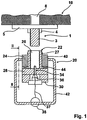
- the rock anchor generally designated 1
- the rock anchor comprises the anchor rod 8 from which a part 3 projects freely downwards out of the ridge.
- an anchor plate 5 is fastened to the protruding part of the anchor rod 3 by means of an anchor nut 4, which construction protects the ridges 10.
- the stopper 20 which can also be referred to as a stop lug, comprises a screw-22, wherein the screw 22 is provided with an internal thread 26, wherein the Screw-22 at the end a collar 28 shows.
- the screw head 30 (eg formed in the manner of the tip of a screwdriver), wherein the screw head 30 of the connection with a Aufschraubvorraum serves to the screw 22 with the Internal thread 26 to screw on the protruding part of the anchor rod 3 of the rock anchor 1 from the bottom can.
- the designated anchor member 40 includes the screw 22 with the collar 28, the screw head 30, the ball bearing 44 and the vertebral body 24th
- the vertebral body 24 has as a suspension member on a movable bracket 42, the attachment of, for example, a snap hook of the safety harness of the e.g. Serving with the assembly of loads.
- a snap hook of the safety harness of the e.g. Serving with the assembly of loads there is an axial ball bearing 44 between the end face of the sleeve-shaped vertebral body 24 and the collar 28 on the screw-in sleeve so that the friction between the vertebral body 24 and the collar 28 is reduced when the vertebral body 24 surrounds the screw-in sleeve fixedly connected to the collar 28 22 turns.
- Secured is the screw 22 with the vertebral body 24 by a locking ring 27 z. B. in the form of a snap ring.
- the collar 28 and the screw head 30 to the screw 22 have a bore 34.
- the bore 34 serves to receive a pin 36 as a display member for determining the depth of screwing the screw 22 on the protruding part 3 of the anchor rod 8 of the rock anchor 1. That is when the pin 36 abuts with its end face against the end face of the anchor rod 8 of the rock anchor 1, this is then ejected from the bore 34. The result is that it falls down and hanging on the safety cable 37, which is attached via a mounting ring 38 on the bracket 42 down. This will cause the person to unscrew the Stop device 20 performs, to recognize that the stopper 20 with the anchor rod 8 over the required number of threads, namely in particular four, is in communication.
Landscapes
- Engineering & Computer Science (AREA)
- Mining & Mineral Resources (AREA)
- Structural Engineering (AREA)
- Life Sciences & Earth Sciences (AREA)
- General Life Sciences & Earth Sciences (AREA)
- Geochemistry & Mineralogy (AREA)
- Geology (AREA)
- Piles And Underground Anchors (AREA)
- Surgical Instruments (AREA)
- Emergency Lowering Means (AREA)
Description
- Die Erfindung betrifft ein Befestigungssystem an der Firste einer Strecke unter Tage oder im Tunnelbau, wobei das Befestigungssystem einen Gebirgsanker umfasst, an dem eine Anschlageinrichtung befestigt wird. Gebirgsanker sind aus dem Stand der Technik hinreichend bekannt. Diesbezüglich wird beispielhaft auf die
WO 2012/053965 A1 ,US 4958796 undUS 2012/155970 verwiesen.
Gebirgsanker bestehen üblicherweise aus einer Ankerstange, die in die Firste hineinragt, wobei endseitig an der Ankerstange mit einer Ankermutter eine Ankerplatte angebracht ist. Mithilfe dieser Gebirgsanker wird die Strecke im Stoß- und Firstbereich gesichert. Durch solche Gebirgsanker soll insbesondere das Herabfallen von plattenförmigen Gesteinsschichten oder auch Salzschichten verhindert werden. Das heißt, derartige Gebirgsanker dienen der Stabilisierung der Strecke.
Nun ist aus dem Stand der Technik ebenfalls bekannt, Gebirgsanker als Lastanker zu verwenden und dazu an derartigen Gebirgsankern Lastaufnahmemittel (z. B. Ösen zum Anhängen von Lasten) anzubringen. Hierbei ist im einfachsten Fall vorgesehen, dass von dem Gebirgsanker ein Teil der mit einem Gewinde versehenen Ankerstange aus der Firste herausragt, auf die die entsprechenden Lastaufnahmemittel mit einem Innengewinde aufgeschraubt werden. Derartige Lastaufnahmemittel dienen der Befestigung von Lasten, wie z.B. von Versorgungsleitungen (Rohren), Stromkabeln oder auch Beleuchtungseinrichtungen. Hieraus wird deutlich, dass der Einsatzzweck derartiger Gebirgsanker vielfältig ist. - Für die Anbringung derartiger Gebirgsanker sowohl im - bzw.Stoß - als auch Firstbereich sind Vorrichtungen bekannt, die vom Boden aus die Einbringung derartiger Anker ermöglichen.
- Bei der Montage, oder Demontage von Anlagen oder auch bei Reparatur- und Instandhaltungsarbeiten ist unter Tage ab 1 m Arbeitshöhe eine ordnungsgemäße Sicherung der dort arbeitenden Personen gegen Absturz vorzunehmen.
- Eine mögliche Vorgehensweise, um z. B. bei der Montage oder Demontage von Anlagen eine Absturzsicherung zu gewährleisten, ist, dass die Personen mit Hilfe einer Hebebühne mit entsprechendem Geländer bis in die Arbeitshöhe angehoben werden, um die entsprechenden Arbeiten vornehmen zu können. Diese und auch andere technische Maßnahmen zum Schutze vor Absturz (wie z.B. der Aufbau von Gerüsten) sind zum Teil sehr aufwendig und umgebungsbedingt bzw. auch situationsbedingt schwierig umzusetzen.
- Um nun eine mit geringem Aufwand nutzbare aber wirksame und den Anforderungen der Arbeitssicherheit genügende Absturzsicherung der die Arbeiten vornehmenden Personen zu ermöglichen, ist Gegenstand der vorliegenden Erfindung ein Befestigungssystem zur Anordnung an der Firste unter Tage. Ein Befestigungssystem als Absturzsicherung, das den Anforderungen des Arbeitsschutzes genügt, zeichnet sich erfindungsgemäß durch die Merkmale des Anspruchs 1 aus.
- Gegenstand der Erfindung ist demzufolge, dass die Anschlageinrichtung zum Gebirgsanker frei drehbar mit dem Gebirgsanker verbunden ist. Dies vor dem folgenden Hintergrund: Die Personen, die die Montagearbeiten ausführen, bewegen sich und sie drehen sich u. U. auch um die eigene Achse. Insbesondere kann im Falle eines Absturzes die durch die Anschlageinrichtung gesicherte Person an der Sicherungsleine schwingen. Dadurch, dass die Anschlageinrichtung auf dem Gebirgsanker frei drehbar ist (Drehwirbelfunktion), besteht nicht die Gefahr, dass sie sich vom Gebirgsanker abdreht, wenn die gesicherte Person über ein Geschirr mit den entsprechenden Komponenten durch einen Karabinerhaken mit der Anschlageinrichtung verbunden ist.
- Aus den oben dargelegten Gründen verbietet es sich, dass sich Personen mittels Karabinerhaken an den Lastaufnahmemitteln sichern, die zur Aufnahme von Lasten am Gebirgsanker befestigt sind oder werden. Die in der zuvor abgehandelten
WO 2012/053965 A1 beschriebene Öse ist durch ein Gewinde unmittelbar und nicht frei drehbar mit dem eigentlichen Gebirgsanker verbunden und somit als Absturzsicherung ungeeignet. - Grundsätzlich ist das erfindungsgemäße Befestigungssystem also überall dort einsetzbar, wo eine Personensicherung gegen Absturz erforderlich ist. Dies ist bei einer Arbeitshöhe von über einem Meter der Fall, wenn sonstigen Sicherungseinrichtungen nicht vorhanden oder situationsbedingt schwer einsetzbar sind.
- Vorteilhafte Merkmale und Ausgestaltungen der Erfindung ergeben sich aus den Unteransprüchen.
- So ist insbesondere vorgesehen, dass die Anschlageinrichtung eine Einschraubhülse zur Verbindung mit dem Gebirgsanker aufweist. Vorteilhaft ist hierbei eine Gewindeverbindung zwischen dem Gebirgsanker und dem Ankerglied vorgesehen, wobei insbesondere als Gewinde ein sogenanntes selbsthemmendes Gewinde, beispielsweise in Form eines Trapezgewindes eingesetzt wird. Dies deshalb, um ein Abdrehen des Gewindes zu vermeiden. Im Einzelnen zeichnet sich die Anschlageinrichtung durch eine Einschraubhülse mit Innengewinde aus, wobei die Einschraubhülse auf die Ankerstange des Gebirgsankers aufschraubbar ist. Des Weiteren besitzt sie vorteilhaft einen Bund zur Aufnahme eines hülsenförmigen Wirbelkörpers, wobei der Wirbelkörper ein Einhängeglied, z. B. in Form eines Bügels aufweist, wobei das Einhängeglied der Aufnahme beispielsweise eines Karabinerhakens des Sicherungsgeschirrs der daran befestigten Person dient. Nach einem besonders vorteilhaften Merkmal ist vorgesehen, dass zwischen Bund und Wirbelkörper ein Lager angeordnet ist, insbesondere ein Axialkugellager, das die Reibung zwischen dem hülsenförmigen Wirbelkörper einerseits und dem Bund an der Einschraubhülse andererseits minimiert. Denkbar ist allerdings nicht nur der Einsatz eines Axiallagers in Form eines Kugellagers, sondern auch der Einsatz eines entsprechenden Gleitlagers. Hierdurch wird erreicht, dass sich der Wirbelkörper mit geringen Reibungskräften frei drehen kann, ohne dass sich die Ankerhülse von der Ankerstange des Gebirgsankers löst.
- Nach einem weiteren vorteilhaften Merkmal ist vorgesehen, dass an dem Bund der Einschraubhülse ein Schraubkopf zum Ansetzen eines Werkzeugs angeordnet ist. Der Schraubkopf kann hierbei nach Art der Spitze eines Schraubendrehers ausgebildet sein, wodurch die Möglichkeit eröffnet wird, vom Boden aus mithilfe einer Stange und der entsprechenden Aufschraubvorrichtung, die endseitig einen im Querschnitt U-förmigen Werkzeugkopf zur Aufnahme des Schraubkopfes aufweist, die Anschlagöse auf die Ankerstange des Gebirgsankers aufzudrehen.
- Nach einem weiteren vorteilhaften Merkmal der Erfindung ist vorgesehen, dass die Anschlageinrichtung ein Anzeigeglied zur Bestimmung der Einschraubtiefe der Einschraubhülse auf der Ankerstange des Gebirgsankers aufweist. Das heißt, dass durch dieses Anzeigeglied der Person, die das Aufdrehen der Anschlageinrichtung auf die Ankerstange des Gebirgsankers vom Boden aus mit Hilfe der zuvor erwähnten Stange vornimmt, kenntlich gemacht wird, dass für eine sichere Anbringung der Anschlageinrichtung am Gebirgsanker eine entsprechende Anzahl von Gewindegängen von Einschraubhülse und Ankerstange des Gebirgsankers miteinander in Eingriff stehen. Insbesondere ist vorgesehen, dass Einschraubhülse und Ankerstange über mindestens vier Gewindegänge miteinander in Eingriff stehen. Die Anzahl der Gewindegänge kann in Abhängigkeit der Ankereigenschaften auch variieren.
- Das Anzeigeglied ist hierbei insbesondere als Stift ausgebildet, wobei der Stift in einer Bohrung im Schraubkopf und / oder im Bund der Einschraubhülse einsitzt und mit einem Ende in den Hohlraum der Einschraubhülse hineinragt. Die Fixierung des Anzeigegliedes in der Anschlageinrichtung erfolgt hierbei kraftschlüssig, beispielsweise über Reibung. Hieraus wird deutlich, dass das Maß, mit welchem der Stift in die Einschraubhülse hineinragt, die minimale Aufschraubtiefe der Ankerhülse auf den Schraubbolzen des Gebirgsankers bestimmt. Denn bei Erreichen der entsprechenden Aufschraubtiefe wird durch die Ankerstange des Gebirgsankers der Stift aus der Bohrung herausgedrückt, er fällt ab (ggf. aufgefangen durch ein Fangseil, welches mit einem Befestigungsring an der Anschlageinrichtung gehalten wird), und die Person, die das Aufschrauben der Anschlageinrichtung vornimmt, weiß, dass die entsprechende minimale Aufschraubtiefe erreicht worden ist.
- D. h. zur Sicherung von Personen bei Arbeiten in größerer Höhe wird nun wie folgt vorgegangen: Der Gebirgsanker weist einen über das Gebirge vorstehenden Gewindeansatz auf. Auf diesen Gewindeansatz wird ggf. mit Hilfe einer entsprechend langen Stange, z. B. einer Teleskopstange, mit der entsprechenden Aufschraubvorrichtung, die erfindungsgemäße Anschlageinrichtung aufgeschraubt. Danach wird mit gegebenenfalls der gleichen Stange der Karabinerhaken mit dem Einhängeglied (z. B. in Form eines Bügels) der Anschlageinrichtung verbunden. Alsdann kann der Aufstieg auf Arbeitshöhe beginnen.
Die Anschlageinrichtung kann mehrfach verwendet werden. - Anhand der Zeichnungen wird die Erfindung beispielhaft näher erläutert.
- Fig. 1
- zeigt hierbei eine Seitenansicht im Schnitt auf das Befestigungssystem, also der Anschlageinrichtung 20 mit dem im Gebirge einsitzenden Gebirgsanker 1;
- Fig. 2
- zeigt eine Ansicht gemäß der Linie II-II aus
Fig. 1 . - Der insgesamt mit 1 bezeichnete Gebirgsanker umfasst die Ankerstange 8 von der ein Teil 3 frei nach unten aus der Firste ragt. Im Bereich des Übergangs zur Firste 10 ist an dem herausragenden Teil der Ankerstange 3 eine Ankerplatte 5 mit Hilfe einer Ankermutter 4 befestigt, welche Konstruktion die Firste 10 absichert. Auf die Fixierung des Gebirgsankers 1 im Gebirge wird an dieser Stelle nicht näher eingegangen. Gegenstand der Erfindung ist nun der Gebirgsanker 1 in Verbindung mit der Anschlageinrichtung 20 bzw. die Anschlageinrichtung selbst. Die Anschlageinrichtung 20, die auch als Anschlagsöse bezeichnet werden kann, umfasst eine Einschraubhülse 22, wobei die Einschraubhülse 22 mit einem Innengewinde 26 versehen ist, wobei die Einschraubhülse 22 endseitig einen Bund 28 zeigt. An dem Bund 28 befindet sich der Schraubkopf 30 (z. B. nach Art der Spitze eines Schraubendrehers ausgebildet), wobei der Schraubkopf 30 der Verbindung mit einer Aufschraubvorrichtung dient, um die Einschraubhülse 22 mit dem Innengewinde 26 auf den herausragenden Teil der Ankerstange 3 des Gebirgsankers 1 vom Boden aus aufschrauben zu können.
- Das mit 40 bezeichnete Ankerglied umfasst die Einschraubhülse 22 mit dem Bund 28, dem Schraubkopf 30, das Kugellager 44 sowie den Wirbelkörper 24.
- Auf dem Bund 28 ruht der mit 24 bezeichnete hülsenförmige Wirbelkörper. Der Wirbelkörper 24 weist als Einhängeglied einen beweglichen Bügel 42 auf, der dem Einhängen beispielsweise eines Karabinerhakens des Sicherungsgeschirres der z.B. mit der Montage von Lasten beschäftigten Person dient. Zwischen der Stirnseite des hülsenförmigen Wirbelkörpers 24 und dem Bund 28 an der Einschraubhülse 22 befindet sich beispielsweise ein Axialkugellager 44, sodass die Reibung zwischen dem Wirbelkörper 24 und dem Bund 28 vermindert ist, wenn sich der Wirbelkörper 24 um die fest mit dem Bund 28 verbundene Einschraubhülse 22 dreht. Insofern besteht ein geringfügiger radialer Abstand zwischen dem hülsenförmigen Wirbelkörper und der Einschraubhülse. Gesichert ist die Einschraubhülse 22 mit dem Wirbelkörper 24 durch einen Sicherungsring 27 z. B. in Form eines Sprengrings.
- Der Bund 28 und der Schraubkopf 30 an der Einschraubhülse 22 besitzen eine Bohrung 34. Die Bohrung 34 dient der Aufnahme eines Stiftes 36 als Anzeigeglied zur Bestimmung der Einschraubtiefe der Einschraubhülse 22 auf dem herausragenden Teil 3 der Ankerstange 8 des Gebirgsankers 1. Das heißt, dass wenn der Stift 36 mit seiner Stirnseite an die Stirnseite der Ankerstange 8 des Gebirgsankers 1 anstößt, dieser dann aus der Bohrung 34 ausgestoßen wird. Die Folge ist, dass er herabfällt und an dem Fangseil 37, welches über einen Befestigungsring 38 am Bügel 42 befestigt ist, herunter hängt. Hierdurch wird der Person, die das Aufschrauben der Anschlageinrichtung 20 durchführt, zu erkennen gegeben, dass die Anschlageinrichtung 20 mit der Ankerstange 8 über die erforderliche Anzahl von Gewindegängen, nämlich insbesondere vier, in Verbindung steht.
-
- 1
- Gebirgsanker
- 3
- aus der Firste herausragendes Ende der Ankerstange
- 4
- Ankermutter
- 5
- Ankerplatte
- 8
- Ankerstange
- 10
- Firste
- 20
- Anschlageinrichtung
- 22
- Einschraubhülse
- 24
- Wirbelkörper
- 26
- Innengewinde
- 27
- Sicherungsring
- 28
- Bund
- 30
- Schraubkopf
- 34
- Bohrung
- 36
- Stift (Anzeigeglied)
- 37
- Fangseil für Stift
- 38
- Befestigungsring für Fangseil
- 40
- Ankerglied
- 42
- Bügel (Einhängeglied)
- 44
- Kugellager
Claims (5)
- Befestigungssystem der Firste (10) einer Strecke unter Tage, wobei das Befestigungssystem einen Gebirgsanker (1) umfasst, an dem eine Anschlageinrichtung (20) befestigbar ist, wobei die Anschlageinrichtung (20) relativ zum Gebirgsanker (1) frei drehbar mit dem Gebirgsanker (1) verbunden ist, dadurch gekennzeichnet
dass die Anschlageinrichtung (20) eine Einschraubhülse (22) mit Innengewinde (26) zur Verbindung mit dem Gebirgsanker (1) aufweist und die Anschlageinrichtung (20) durch eine Gewindeverbindung mit einen herausragenden Teil (3) der Ankerstange (8) des Gebirgsankers (1) in Verbindung steht, wobei die Einschraubhülse (22) einen Bund (28) zur Aufnahme eines hülsenförmigen Wirbelkörpers (24) mit einem Einhängeglied aufweist, dass an dem Bund (28) ein Schraubkopf (30) zum Ansetzen eines Werkzeugs angeordnet ist. - Befestigungssystem nach Anspruch 1,
dadurch gekennzeichnet,
dass die Anschlageinrichtung (20) ein Anzeigeglied zur Bestimmung der Einschraubtiefe zwischen der Einschraubhülse (22) und dem herausragenden Teil (3) der Ankerstange (8) des Gebirgsankers (1) aufweist. - Befestigungssystem nach Anspruch 2,
dadurch gekennzeichnet,
dass das Anzeigeglied als Stift (36) ausgebildet ist. - Befestigungssystem nach Anspruch 3,
dadurch gekennzeichnet,
dass der Stift (36) in einer Bohrung (34) in Schraubkopf (30) und Bund (28) einsitzt und mit einem Ende in den Hohlraum der Einschraubhülse (22) hineinragt - Befestigungssystem nach einem der voranstehenden Ansprüche ,
dadurch gekennzeichnet,
dass das Anzeigeglied (36) kraftschlüssig vom Schraubkopf (30) oder Bund (28) der Anschlageinrichtung (20) aufgenommen wird.
Priority Applications (1)
| Application Number | Priority Date | Filing Date | Title |
|---|---|---|---|
| PL15716406T PL3111045T3 (pl) | 2014-02-26 | 2015-02-25 | Podziemny układ mocujący, zawierający kotwę skalną z urządzeniem zatrzymującym |
Applications Claiming Priority (2)
| Application Number | Priority Date | Filing Date | Title |
|---|---|---|---|
| DE102014002566.7A DE102014002566A1 (de) | 2014-02-26 | 2014-02-26 | Befestigungssystem unter Tage umfassend einen Gebirgsanker mit Anschlageinrichtung |
| PCT/DE2015/000091 WO2015127922A1 (de) | 2014-02-26 | 2015-02-25 | Befestigungssystem unter tage umfassend einen gebirgsanker mit anschlageinrichtung |
Publications (2)
| Publication Number | Publication Date |
|---|---|
| EP3111045A1 EP3111045A1 (de) | 2017-01-04 |
| EP3111045B1 true EP3111045B1 (de) | 2019-04-03 |
Family
ID=52874897
Family Applications (1)
| Application Number | Title | Priority Date | Filing Date |
|---|---|---|---|
| EP15716406.2A Active EP3111045B1 (de) | 2014-02-26 | 2015-02-25 | Befestigungssystem unter tage umfassend einen gebirgsanker mit anschlageinrichtung |
Country Status (7)
| Country | Link |
|---|---|
| US (1) | US20170067340A1 (de) |
| EP (1) | EP3111045B1 (de) |
| CA (1) | CA2940767A1 (de) |
| DE (2) | DE102014002566A1 (de) |
| ES (1) | ES2733487T3 (de) |
| PL (1) | PL3111045T3 (de) |
| WO (1) | WO2015127922A1 (de) |
Families Citing this family (4)
| Publication number | Priority date | Publication date | Assignee | Title |
|---|---|---|---|---|
| CN107191211B (zh) * | 2017-07-10 | 2023-03-31 | 河南理工大学 | 用于锚固破碎顶板煤体的叉形锚杆及其安装方法 |
| AU2018319717B2 (en) | 2017-08-22 | 2023-11-23 | Sandvik Intellectual Property Ab | Rock bolt with meshing adapter |
| AU2018373535B2 (en) | 2017-11-27 | 2023-11-30 | Sandvik Intellectual Property Ab | Rock bolt with meshing adapter |
| CN108915748B (zh) * | 2018-07-10 | 2019-09-13 | 太原理工大学 | 一种监测锚杆安装预紧力的装置及其使用方法 |
Family Cites Families (14)
| Publication number | Priority date | Publication date | Assignee | Title |
|---|---|---|---|---|
| US3504498A (en) * | 1968-07-26 | 1970-04-07 | Lee Triplett | Shaft securement structure |
| GB1592424A (en) * | 1977-01-29 | 1981-07-08 | Shimoda Y | Apparatus for forcing an auger screw into the ground |
| DE7924597U1 (de) * | 1979-08-30 | 1979-11-22 | Saarlaendische Gesellschaft Fuer Grubenausbau Und Technik Mbh, 6682 Ottweiler | Ankerbolzen |
| DE3320272A1 (de) * | 1983-05-11 | 1984-11-22 | Müller & Borggräfe KG, 5820 Gevelsberg | Verfahren und vorrichtung zum aufhaengen von lasten, insbesondere von bahnschienen im untertagebetrieb mit hilfe von gebirgsankern |
| DE3342917A1 (de) * | 1983-11-17 | 1985-05-30 | Müller & Borggräfe KG, 5820 Gevelsberg | Gebirgsanker mit einem fuer den anschluss wenigstens einer lastkette vorgesehenen anschlussblech |
| DE3411238A1 (de) * | 1984-03-27 | 1985-10-10 | Müller & Borggräfe KG, 5820 Gevelsberg | Vorrichtung zur zugstrangbefestigung von aufgehaengten ausruestungen des untertagebetriebes an gebirgsankern |
| US4958796A (en) * | 1989-10-12 | 1990-09-25 | John Bernosky | Coupling or connector for securing a load-bearing support to a head of a bolt |
| DE20011873U1 (de) * | 2000-06-29 | 2000-11-09 | Gebr. Philipp GmbH, 63741 Aschaffenburg | Einschraubanschlagmittel für Betonfertigteile |
| AUPR994002A0 (en) * | 2002-01-11 | 2002-01-31 | Fergusson, Jeffrey Robert | A rock bolt |
| MXPA05003034A (es) * | 2002-09-21 | 2005-09-08 | Patrick W Breslin | Montaje sujetador de tornillo de chaveta seccionada y metodo. |
| US6857176B2 (en) * | 2002-11-19 | 2005-02-22 | John Machado | Tandem wheel unlocking assist device |
| US7510351B2 (en) * | 2006-03-28 | 2009-03-31 | Price Herbert S | Method for supporting a subsurface material |
| AU2011236039B2 (en) | 2010-10-18 | 2012-06-28 | Sandvik Intellectual Property Ab | Rock bolt hanger system |
| US20120155970A1 (en) * | 2010-12-15 | 2012-06-21 | Fci Holdings Delaware, Inc. | Mine Roof Bolt With End Fitting |
-
2014
- 2014-02-26 DE DE102014002566.7A patent/DE102014002566A1/de not_active Withdrawn
-
2015
- 2015-02-25 US US15/122,046 patent/US20170067340A1/en not_active Abandoned
- 2015-02-25 CA CA2940767A patent/CA2940767A1/en not_active Abandoned
- 2015-02-25 WO PCT/DE2015/000091 patent/WO2015127922A1/de not_active Ceased
- 2015-02-25 PL PL15716406T patent/PL3111045T3/pl unknown
- 2015-02-25 EP EP15716406.2A patent/EP3111045B1/de active Active
- 2015-02-25 DE DE112015000988.4T patent/DE112015000988A5/de not_active Withdrawn
- 2015-02-25 ES ES15716406T patent/ES2733487T3/es active Active
Non-Patent Citations (1)
| Title |
|---|
| None * |
Also Published As
| Publication number | Publication date |
|---|---|
| DE102014002566A1 (de) | 2015-08-27 |
| WO2015127922A1 (de) | 2015-09-03 |
| CA2940767A1 (en) | 2015-09-03 |
| US20170067340A1 (en) | 2017-03-09 |
| DE112015000988A5 (de) | 2016-11-03 |
| ES2733487T3 (es) | 2019-11-29 |
| EP3111045A1 (de) | 2017-01-04 |
| PL3111045T3 (pl) | 2020-03-31 |
Similar Documents
| Publication | Publication Date | Title |
|---|---|---|
| DE2635805C2 (de) | ||
| EP3529504A1 (de) | Spannvorrichtung für seile und ketten, mit gewindespindel und ratscheneinheit | |
| WO2015127922A1 (de) | Befestigungssystem unter tage umfassend einen gebirgsanker mit anschlageinrichtung | |
| EP0161652B1 (de) | Ringschraube | |
| EP2844601B1 (de) | Ringschraube mit gleitscheibe | |
| DE202009004831U1 (de) | Bauwerkanker sowie Bauwerkankersystem | |
| EP2698336B1 (de) | Anschlagöse | |
| DE102010061459B4 (de) | Spannschloss eines Ratschenlastspanners zum Verzurren von Ladungen | |
| DE102012105985A1 (de) | Vorrichtung zur Sicherung von Personen gegen Absturz | |
| DE3204930A1 (de) | Aufhaengung, insbesondere fuer bauteile von bergwerksmaschinen | |
| EP2966233A1 (de) | Vorrichtung zur abgehängten befestigung einer zwischendecke eines tunnels | |
| DE202008009273U1 (de) | Zugstabsystem | |
| EP4219863A1 (de) | Sperranker | |
| EP3473779A1 (de) | Verbindungselement mit feststellelement sowie verfahren zum feststellen des verbindungselements | |
| EP2039948A1 (de) | Montagehilfsmittel für Elektrodenstrang-Montage | |
| EP3921570A1 (de) | Fallsicherungsvorrichtung für ein medizinisches tragsystem, tragsystem für ein medizinisches gerät, verfahren zur anbringung einer fallsicherungsvorrichtung an einem tragsystem | |
| DE3146829C2 (de) | Innenbefahrvorrichtung für Großbehälter | |
| DE202012012390U1 (de) | Gurtsystem zur Personensicherung | |
| DE102019113481A1 (de) | Vorrichtung zur Sicherung von Personen gegen Absturz | |
| DE102012104386A1 (de) | Ackerschiene | |
| DE20206551U1 (de) | Seilförmiger Anker | |
| DE860100C (de) | Lasthaken fuer Hebezeuge | |
| AT13457U1 (de) | Anschlagöse | |
| DE202011002965U1 (de) | Vorrichtung zum Aufschrauben von Muttern auf Gewindestangen | |
| DE202025001867U1 (de) | Gelenkadapter für ein modulares Stützensystem |
Legal Events
| Date | Code | Title | Description |
|---|---|---|---|
| PUAI | Public reference made under article 153(3) epc to a published international application that has entered the european phase |
Free format text: ORIGINAL CODE: 0009012 |
|
| STAA | Information on the status of an ep patent application or granted ep patent |
Free format text: STATUS: REQUEST FOR EXAMINATION WAS MADE |
|
| 17P | Request for examination filed |
Effective date: 20160822 |
|
| AK | Designated contracting states |
Kind code of ref document: A1 Designated state(s): AL AT BE BG CH CY CZ DE DK EE ES FI FR GB GR HR HU IE IS IT LI LT LU LV MC MK MT NL NO PL PT RO RS SE SI SK SM TR |
|
| AX | Request for extension of the european patent |
Extension state: BA ME |
|
| DAX | Request for extension of the european patent (deleted) | ||
| REG | Reference to a national code |
Ref country code: DE Ref legal event code: R079 Ref document number: 502015008557 Country of ref document: DE Free format text: PREVIOUS MAIN CLASS: E21D0021000000 Ipc: E21D0021020000 |
|
| GRAP | Despatch of communication of intention to grant a patent |
Free format text: ORIGINAL CODE: EPIDOSNIGR1 |
|
| STAA | Information on the status of an ep patent application or granted ep patent |
Free format text: STATUS: GRANT OF PATENT IS INTENDED |
|
| RIC1 | Information provided on ipc code assigned before grant |
Ipc: E21D 21/00 20060101ALI20180927BHEP Ipc: E21D 21/02 20060101AFI20180927BHEP |
|
| INTG | Intention to grant announced |
Effective date: 20181016 |
|
| GRAS | Grant fee paid |
Free format text: ORIGINAL CODE: EPIDOSNIGR3 |
|
| GRAA | (expected) grant |
Free format text: ORIGINAL CODE: 0009210 |
|
| STAA | Information on the status of an ep patent application or granted ep patent |
Free format text: STATUS: THE PATENT HAS BEEN GRANTED |
|
| AK | Designated contracting states |
Kind code of ref document: B1 Designated state(s): AL AT BE BG CH CY CZ DE DK EE ES FI FR GB GR HR HU IE IS IT LI LT LU LV MC MK MT NL NO PL PT RO RS SE SI SK SM TR |
|
| REG | Reference to a national code |
Ref country code: GB Ref legal event code: FG4D Free format text: NOT ENGLISH |
|
| REG | Reference to a national code |
Ref country code: CH Ref legal event code: EP Ref country code: AT Ref legal event code: REF Ref document number: 1115969 Country of ref document: AT Kind code of ref document: T Effective date: 20190415 |
|
| REG | Reference to a national code |
Ref country code: DE Ref legal event code: R096 Ref document number: 502015008557 Country of ref document: DE |
|
| REG | Reference to a national code |
Ref country code: IE Ref legal event code: FG4D Free format text: LANGUAGE OF EP DOCUMENT: GERMAN |
|
| REG | Reference to a national code |
Ref country code: NL Ref legal event code: MP Effective date: 20190403 |
|
| REG | Reference to a national code |
Ref country code: LT Ref legal event code: MG4D |
|
| PG25 | Lapsed in a contracting state [announced via postgrant information from national office to epo] |
Ref country code: NL Free format text: LAPSE BECAUSE OF FAILURE TO SUBMIT A TRANSLATION OF THE DESCRIPTION OR TO PAY THE FEE WITHIN THE PRESCRIBED TIME-LIMIT Effective date: 20190403 |
|
| PG25 | Lapsed in a contracting state [announced via postgrant information from national office to epo] |
Ref country code: FI Free format text: LAPSE BECAUSE OF FAILURE TO SUBMIT A TRANSLATION OF THE DESCRIPTION OR TO PAY THE FEE WITHIN THE PRESCRIBED TIME-LIMIT Effective date: 20190403 Ref country code: NO Free format text: LAPSE BECAUSE OF FAILURE TO SUBMIT A TRANSLATION OF THE DESCRIPTION OR TO PAY THE FEE WITHIN THE PRESCRIBED TIME-LIMIT Effective date: 20190703 Ref country code: CZ Free format text: LAPSE BECAUSE OF FAILURE TO SUBMIT A TRANSLATION OF THE DESCRIPTION OR TO PAY THE FEE WITHIN THE PRESCRIBED TIME-LIMIT Effective date: 20190403 Ref country code: LT Free format text: LAPSE BECAUSE OF FAILURE TO SUBMIT A TRANSLATION OF THE DESCRIPTION OR TO PAY THE FEE WITHIN THE PRESCRIBED TIME-LIMIT Effective date: 20190403 Ref country code: HR Free format text: LAPSE BECAUSE OF FAILURE TO SUBMIT A TRANSLATION OF THE DESCRIPTION OR TO PAY THE FEE WITHIN THE PRESCRIBED TIME-LIMIT Effective date: 20190403 Ref country code: PT Free format text: LAPSE BECAUSE OF FAILURE TO SUBMIT A TRANSLATION OF THE DESCRIPTION OR TO PAY THE FEE WITHIN THE PRESCRIBED TIME-LIMIT Effective date: 20190803 Ref country code: AL Free format text: LAPSE BECAUSE OF FAILURE TO SUBMIT A TRANSLATION OF THE DESCRIPTION OR TO PAY THE FEE WITHIN THE PRESCRIBED TIME-LIMIT Effective date: 20190403 Ref country code: SE Free format text: LAPSE BECAUSE OF FAILURE TO SUBMIT A TRANSLATION OF THE DESCRIPTION OR TO PAY THE FEE WITHIN THE PRESCRIBED TIME-LIMIT Effective date: 20190403 |
|
| PG25 | Lapsed in a contracting state [announced via postgrant information from national office to epo] |
Ref country code: BG Free format text: LAPSE BECAUSE OF FAILURE TO SUBMIT A TRANSLATION OF THE DESCRIPTION OR TO PAY THE FEE WITHIN THE PRESCRIBED TIME-LIMIT Effective date: 20190703 Ref country code: LV Free format text: LAPSE BECAUSE OF FAILURE TO SUBMIT A TRANSLATION OF THE DESCRIPTION OR TO PAY THE FEE WITHIN THE PRESCRIBED TIME-LIMIT Effective date: 20190403 Ref country code: RS Free format text: LAPSE BECAUSE OF FAILURE TO SUBMIT A TRANSLATION OF THE DESCRIPTION OR TO PAY THE FEE WITHIN THE PRESCRIBED TIME-LIMIT Effective date: 20190403 Ref country code: GR Free format text: LAPSE BECAUSE OF FAILURE TO SUBMIT A TRANSLATION OF THE DESCRIPTION OR TO PAY THE FEE WITHIN THE PRESCRIBED TIME-LIMIT Effective date: 20190704 |
|
| REG | Reference to a national code |
Ref country code: ES Ref legal event code: FG2A Ref document number: 2733487 Country of ref document: ES Kind code of ref document: T3 Effective date: 20191129 |
|
| REG | Reference to a national code |
Ref country code: DE Ref legal event code: R081 Ref document number: 502015008557 Country of ref document: DE Owner name: K+S MINERALS AND AGRICULTURE GMBH, DE Free format text: FORMER OWNER: K+S KALI GMBH, 34131 KASSEL, DE |
|
| PG25 | Lapsed in a contracting state [announced via postgrant information from national office to epo] |
Ref country code: IS Free format text: LAPSE BECAUSE OF FAILURE TO SUBMIT A TRANSLATION OF THE DESCRIPTION OR TO PAY THE FEE WITHIN THE PRESCRIBED TIME-LIMIT Effective date: 20190803 |
|
| REG | Reference to a national code |
Ref country code: DE Ref legal event code: R097 Ref document number: 502015008557 Country of ref document: DE |
|
| PG25 | Lapsed in a contracting state [announced via postgrant information from national office to epo] |
Ref country code: RO Free format text: LAPSE BECAUSE OF FAILURE TO SUBMIT A TRANSLATION OF THE DESCRIPTION OR TO PAY THE FEE WITHIN THE PRESCRIBED TIME-LIMIT Effective date: 20190403 Ref country code: SK Free format text: LAPSE BECAUSE OF FAILURE TO SUBMIT A TRANSLATION OF THE DESCRIPTION OR TO PAY THE FEE WITHIN THE PRESCRIBED TIME-LIMIT Effective date: 20190403 Ref country code: DK Free format text: LAPSE BECAUSE OF FAILURE TO SUBMIT A TRANSLATION OF THE DESCRIPTION OR TO PAY THE FEE WITHIN THE PRESCRIBED TIME-LIMIT Effective date: 20190403 Ref country code: EE Free format text: LAPSE BECAUSE OF FAILURE TO SUBMIT A TRANSLATION OF THE DESCRIPTION OR TO PAY THE FEE WITHIN THE PRESCRIBED TIME-LIMIT Effective date: 20190403 |
|
| PLBE | No opposition filed within time limit |
Free format text: ORIGINAL CODE: 0009261 |
|
| STAA | Information on the status of an ep patent application or granted ep patent |
Free format text: STATUS: NO OPPOSITION FILED WITHIN TIME LIMIT |
|
| PG25 | Lapsed in a contracting state [announced via postgrant information from national office to epo] |
Ref country code: IT Free format text: LAPSE BECAUSE OF FAILURE TO SUBMIT A TRANSLATION OF THE DESCRIPTION OR TO PAY THE FEE WITHIN THE PRESCRIBED TIME-LIMIT Effective date: 20190403 Ref country code: SM Free format text: LAPSE BECAUSE OF FAILURE TO SUBMIT A TRANSLATION OF THE DESCRIPTION OR TO PAY THE FEE WITHIN THE PRESCRIBED TIME-LIMIT Effective date: 20190403 |
|
| 26N | No opposition filed |
Effective date: 20200106 |
|
| PG25 | Lapsed in a contracting state [announced via postgrant information from national office to epo] |
Ref country code: TR Free format text: LAPSE BECAUSE OF FAILURE TO SUBMIT A TRANSLATION OF THE DESCRIPTION OR TO PAY THE FEE WITHIN THE PRESCRIBED TIME-LIMIT Effective date: 20190403 |
|
| PG25 | Lapsed in a contracting state [announced via postgrant information from national office to epo] |
Ref country code: SI Free format text: LAPSE BECAUSE OF FAILURE TO SUBMIT A TRANSLATION OF THE DESCRIPTION OR TO PAY THE FEE WITHIN THE PRESCRIBED TIME-LIMIT Effective date: 20190403 |
|
| REG | Reference to a national code |
Ref country code: CH Ref legal event code: PL |
|
| REG | Reference to a national code |
Ref country code: BE Ref legal event code: MM Effective date: 20200229 |
|
| PG25 | Lapsed in a contracting state [announced via postgrant information from national office to epo] |
Ref country code: LU Free format text: LAPSE BECAUSE OF NON-PAYMENT OF DUE FEES Effective date: 20200225 Ref country code: MC Free format text: LAPSE BECAUSE OF FAILURE TO SUBMIT A TRANSLATION OF THE DESCRIPTION OR TO PAY THE FEE WITHIN THE PRESCRIBED TIME-LIMIT Effective date: 20190403 |
|
| PG25 | Lapsed in a contracting state [announced via postgrant information from national office to epo] |
Ref country code: CH Free format text: LAPSE BECAUSE OF NON-PAYMENT OF DUE FEES Effective date: 20200229 Ref country code: LI Free format text: LAPSE BECAUSE OF NON-PAYMENT OF DUE FEES Effective date: 20200229 |
|
| PG25 | Lapsed in a contracting state [announced via postgrant information from national office to epo] |
Ref country code: IE Free format text: LAPSE BECAUSE OF NON-PAYMENT OF DUE FEES Effective date: 20200225 Ref country code: FR Free format text: LAPSE BECAUSE OF NON-PAYMENT OF DUE FEES Effective date: 20200229 |
|
| PG25 | Lapsed in a contracting state [announced via postgrant information from national office to epo] |
Ref country code: BE Free format text: LAPSE BECAUSE OF NON-PAYMENT OF DUE FEES Effective date: 20200229 |
|
| REG | Reference to a national code |
Ref country code: AT Ref legal event code: MM01 Ref document number: 1115969 Country of ref document: AT Kind code of ref document: T Effective date: 20200225 |
|
| PG25 | Lapsed in a contracting state [announced via postgrant information from national office to epo] |
Ref country code: AT Free format text: LAPSE BECAUSE OF NON-PAYMENT OF DUE FEES Effective date: 20200225 |
|
| REG | Reference to a national code |
Ref country code: ES Ref legal event code: FD2A Effective date: 20210706 |
|
| PG25 | Lapsed in a contracting state [announced via postgrant information from national office to epo] |
Ref country code: ES Free format text: LAPSE BECAUSE OF NON-PAYMENT OF DUE FEES Effective date: 20200226 |
|
| PG25 | Lapsed in a contracting state [announced via postgrant information from national office to epo] |
Ref country code: MT Free format text: LAPSE BECAUSE OF FAILURE TO SUBMIT A TRANSLATION OF THE DESCRIPTION OR TO PAY THE FEE WITHIN THE PRESCRIBED TIME-LIMIT Effective date: 20190403 Ref country code: CY Free format text: LAPSE BECAUSE OF FAILURE TO SUBMIT A TRANSLATION OF THE DESCRIPTION OR TO PAY THE FEE WITHIN THE PRESCRIBED TIME-LIMIT Effective date: 20190403 |
|
| PG25 | Lapsed in a contracting state [announced via postgrant information from national office to epo] |
Ref country code: MK Free format text: LAPSE BECAUSE OF FAILURE TO SUBMIT A TRANSLATION OF THE DESCRIPTION OR TO PAY THE FEE WITHIN THE PRESCRIBED TIME-LIMIT Effective date: 20190403 |
|
| PG25 | Lapsed in a contracting state [announced via postgrant information from national office to epo] |
Ref country code: PL Free format text: LAPSE BECAUSE OF NON-PAYMENT OF DUE FEES Effective date: 20200225 |
|
| PGFP | Annual fee paid to national office [announced via postgrant information from national office to epo] |
Ref country code: GB Payment date: 20230105 Year of fee payment: 9 Ref country code: DE Payment date: 20221230 Year of fee payment: 9 |
|
| REG | Reference to a national code |
Ref country code: DE Ref legal event code: R119 Ref document number: 502015008557 Country of ref document: DE |
|
| GBPC | Gb: european patent ceased through non-payment of renewal fee |
Effective date: 20240225 |
|
| PG25 | Lapsed in a contracting state [announced via postgrant information from national office to epo] |
Ref country code: DE Free format text: LAPSE BECAUSE OF NON-PAYMENT OF DUE FEES Effective date: 20240903 |
|
| PG25 | Lapsed in a contracting state [announced via postgrant information from national office to epo] |
Ref country code: GB Free format text: LAPSE BECAUSE OF NON-PAYMENT OF DUE FEES Effective date: 20240225 |
|
| PG25 | Lapsed in a contracting state [announced via postgrant information from national office to epo] |
Ref country code: GB Free format text: LAPSE BECAUSE OF NON-PAYMENT OF DUE FEES Effective date: 20240225 Ref country code: DE Free format text: LAPSE BECAUSE OF NON-PAYMENT OF DUE FEES Effective date: 20240903 |