US20120155970A1 - Mine Roof Bolt With End Fitting - Google Patents
Mine Roof Bolt With End Fitting Download PDFInfo
- Publication number
- US20120155970A1 US20120155970A1 US12/968,459 US96845910A US2012155970A1 US 20120155970 A1 US20120155970 A1 US 20120155970A1 US 96845910 A US96845910 A US 96845910A US 2012155970 A1 US2012155970 A1 US 2012155970A1
- Authority
- US
- United States
- Prior art keywords
- mine roof
- roof bolt
- nut
- threaded portion
- end fitting
- Prior art date
- Legal status (The legal status is an assumption and is not a legal conclusion. Google has not performed a legal analysis and makes no representation as to the accuracy of the status listed.)
- Abandoned
Links
Images




Classifications
-
- E—FIXED CONSTRUCTIONS
- E21—EARTH OR ROCK DRILLING; MINING
- E21D—SHAFTS; TUNNELS; GALLERIES; LARGE UNDERGROUND CHAMBERS
- E21D21/00—Anchoring-bolts for roof, floor in galleries or longwall working, or shaft-lining protection
- E21D21/008—Anchoring or tensioning means
-
- E—FIXED CONSTRUCTIONS
- E21—EARTH OR ROCK DRILLING; MINING
- E21D—SHAFTS; TUNNELS; GALLERIES; LARGE UNDERGROUND CHAMBERS
- E21D21/00—Anchoring-bolts for roof, floor in galleries or longwall working, or shaft-lining protection
- E21D21/0093—Accessories
Definitions
- the present invention relates to a mine roof bolt and, more particularly, to a mine roof bolt having an end fitting and a method of installing a mine roof bolt with an end fitting.
- the roof of a mine is conventionally supported by tensioning the roof with steel bolts inserted into bore holes drilled in the mine roof that reinforce the unsupported rock formation above the mine roof.
- the mine roof bolt may be anchored mechanically to the rock formation by engagement of an expansion assembly on the distal end of the mine roof bolt with the rock formation.
- the mine roof bolt may be adhesively bonded to the rock formation with a resin bonding material inserted into the bore hole.
- a combination of mechanical anchoring and resin bonding may also be employed by using both an expansion assembly and resin bonding material.
- a mechanically anchored mine roof bolt typically includes an expansion assembly threaded onto one end of the bolt shaft and a drive head for rotating the bolt.
- a mine roof plate is positioned between the drive head and the mine roof surface.
- the expansion assembly generally includes a multi-prong shell supported by a threaded ring and a plug threaded onto the end of the bolt. When the prongs of the shell engage with rock surrounding a bore hole, and the bolt is rotated about its longitudinal axis, the plug threads downwardly on the shaft to expand the shell into tight engagement with the rock thereby placing the bolt in tension between the expansion assembly and the mine roof surface.
- Resin is typically inserted into the mine roof bore hole in the form of a two component plastic cartridge having one component containing a curable resin composition and another component containing a curing agent (catalyst).
- the two component resin cartridge is inserted into the blind end of the bore hole and the mine roof bolt is inserted into the bore hole such that the end of the mine roof bolt ruptures the two component resin cartridge.
- the compartments within the resin cartridge are shredded and the components are mixed.
- the resin mixture fills the annular area between the bore hole wall and the shaft of the mine roof bolt.
- the mixed resin cures and binds the mine roof bolt to the surrounding rock.
- the mine roof bolt is typically rotated via a drive head. With bolts that are point anchored and tensioned, a breakaway nut may be used to rotate the bolt and subsequently tension the bolt upon curing of the resin bonding material.
- the mine roof bolt is provided with an end having an integral eye or a forged eye nut, which may be used as an anchoring point for a fall protection harness.
- U.S. Pat. Nos. 4,958,796 and 5,474,274, both to Bernosky disclose a coupling that attaches to a bolt head for providing a suspension system from mine roof bolts.
- U.S. Pat. No. 4,958,796, for example shows a variety of mechanisms for attaching an eye nut to a coupler that is in turn attached to the mine roof bolt head (see FIGS. 2-6 ).
- U.S. Patent Application Publication No. 2006/0285928 to Kanflod et al. discloses a swellable bolt that has an internally threaded end that can accept a hanger loop.
- U.S. Pat. No. 6,868,647 to Poldmaa is directed to a mechanism for holding an eye bolt to the roof of a building that utilizes locking nuts.
- a mine roof bolt in one embodiment, includes an elongated body, first and second nuts, and an end fitting.
- the elongated body has a first end and a second end with the first end having a threaded portion.
- the first and second nuts are positioned on the threaded portion of the first end of the elongated body.
- the end fitting is positioned on the threaded portion of the first end of the elongated body between the first and second nuts.
- the end fitting may comprise an eye nut having a body that defines an opening configured to receive the threaded portion of the first end of the elongated body and an eyelet.
- the opening in the body of the eye nut may be threaded.
- the second end of the elongated body may include an angled surface.
- the first and second nuts may engage the end fitting and the elongated body may be formed from rebar.
- the first and second nut may define drive faces and the end fitting may extend away from the first end of the elongated body.
- the mine roof bolt may further include a third nut positioned on the threaded portion of the first end of the elongated body. The third nut may be spaced from the first nut toward the second end of the elongated body.
- a method of installing a mine roof bolt includes positioning a cartridge having resin bonding material within a bore hole and inserting a mine roof bolt into the bore hole and rupturing the cartridge.
- the mine roof bolt has a threaded portion with a rotation nut positioned thereon.
- the method further includes rotating the mine roof bolt via the rotation nut thereby mixing the resin bonding material and positioning a first nut on the threaded portion of the mine roof bolt.
- the method also includes positioning an end fitting on the threaded portion of the mine roof bolt and positioning a second nut on the threaded portion of the mine roof bolt such that the end fitting is positioned between the first and second nuts.
- the end fitting may be an eye nut having a body that defines an opening and an eyelet with the threaded portion of the mine roof bolt being positioned through the opening of the eye nut body.
- the opening in the body of the eye nut may be threaded and the eye nut may be threaded onto the threaded portion of the mine roof bolt.
- the second end of the elongated body may include an angled surface that engages the cartridge when the cartridge is ruptured.
- the method may further include the step of engaging the end fitting with the first and second nuts.
- the first nut may be positioned at about the midpoint of the threaded portion of the mine roof bolt.
- the method may further include removing the first and second nuts and end fitting from the threaded portion of the mine roof bolt prior to rotating the mine roof bolt.
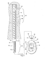
- FIG. 1 is an elevational view of a mine roof bolt according to one embodiment of the present invention
- FIG. 2 is an elevational view of the mine roof bolt of FIG. 1 , showing one step of installing the mine roof bolt in a bore hole;
- FIG. 3 is an elevational view of the mine roof bolt of FIG. 1 , showing a further step of installing the mine roof bolt in a bore hole;
- FIG. 4 is an elevational view of the mine roof bolt of FIG. 1 , showing another step of installing the mine roof bolt in a bore hole;
- FIG. 5 is an elevational view of the mine roof bolt of FIG. 1 , showing yet another step of installing the mine roof bolt in a bore hole;
- FIG. 6 is an elevational view of the mine roof bolt of FIG. 1 , showing the mine roof bolt installed in a bore hole.
- a mine roof bolt 10 includes an elongated body 12 having a first end 14 and a second end 16 .
- the first end 14 includes a threaded portion 18 .
- First and second nuts 20 , 22 are positioned on the threaded portion 18 of the first end 14 of the elongated body 12 .
- the first nut 20 may be positioned at about a midpoint of the threaded portion 18 .
- a third nut or rotation nut 23 is also positioned on the threaded portion 18 of the elongated body 12 .
- the third nut 23 is spaced from the first nut 20 toward the second end 16 of the elongated body 12 . As shown in FIG.
- the third nut 23 is positioned at an end of the threaded portion 18 that is opposite the first end 14 of the elongated body, although the third nut 23 may have other locations along the threaded portion 18 .
- the third nut 23 may be formed integrally with the elongated body 12 .
- An end fitting 24 is positioned on the threaded portion 18 of the first end 14 of the elongated body 12 between the first and second nuts 20 , 22 .
- the end fitting 24 as shown in FIG. 1 , is an eye nut having a body 26 that defines an opening 28 and an eyelet 30 , although other suitable end fittings may be utilized.
- the opening 28 of the body 26 of the end fitting 24 is configured to receive the threaded portion 18 of the first end 14 of the elongated body 12 .
- the opening 28 in the body 26 of the end fitting 24 is threaded and cooperatively engages the threaded portion 18 of the first end 14 of the elongated body 12 .
- the end fitting 24 is a forged steel eye nut having an ultimate load of 50,000 lbs.
- the second end 16 of the elongated body 12 includes an angled surface 32 that is configured to assist in rupturing a resin cartridge, which will be discussed in more detail below. This is not meant to be limiting.
- the second end 16 may alternatively include an expansion assembly mounted on the elongated body 12 , as is known in the art.
- the end fitting 24 is positioned between the first and second nuts 20 , 22 on the threaded portion 18 of the first end 14 of the elongated body 12 such that the end fitting 24 engages the first and second nuts 20 , 22 .
- the first and second nuts 20 , 22 engage the end fitting 24 to sandwich the end fitting 24 between the nuts 20 , 22 .
- the first, second, and third nuts 20 , 22 , 23 define drive faces 34 that are configured to be engaged by a drive tool (not shown).
- the nuts 20 , 22 , 23 are hex jam nuts, although other suitable fasteners may be utilized.
- the elongated body 12 as shown in FIG. 1 , is formed from rebar, although other suitable elongated bodies may be utilized.
- the end fitting 24 extends away from the first end 14 of the elongated body 12 .
- the body 26 of the end fitting 24 and an eyelet 30 extend below the first end 14 of the elongated body 12 with the eyelet 30 being configured to serve as an anchoring point for a fall protection harness (not shown).
- FIGS. 2-6 one embodiment of installing the mine roof bolt 10 in a bore hole 36 defined in rock strata 38 is disclosed.
- the mine roof bolt 10 is installed by positioning a frangible resin cartridge 40 into the bore hole 36 and inserting the mine roof bolt 10 into the bore hole 36 .
- the first and second nuts 20 , 22 and end fitting 24 are removed from the mine roof bolt 10 and the second end 16 of the elongated body 12 of the mine roof bolt 10 is inserted into the bore hole 36 .
- the mine roof bolt 10 is moved axially within the bore hole 36 as indicated by arrow A and is also rotated about a longitudinal axis of the mine roof bolt 10 as indicated by arrow B.
- the mine roof bolt 10 is rotated about its longitudinal axis via the third nut or rotation nut 23 .
- a driving tool (not shown) engages the drive faces 34 of the third nut 23 and rotates the third nut 23 .
- the angled surface 32 on the second end 16 of the elongated body 12 contacts and ruptures the resin cartridge 40 , thereby releasing a curable resin 42 .
- the rotation of the mine roof bolt 10 facilitates the mixing of the contents of the resin cartridge 40 .
- the bolt 10 may also be rotated by repositioning the first and second nuts 20 , 22 on the threaded portion 18 and engaging the second nut 22 with the drive tool such that second nut 22 engages the first nut 20 to cause rotation of the entire mine roof bolt 10 .
- the mine roof bolt 10 is securely anchored within the bore hole 36 .
- the first nut 20 is then positioned on the threaded portion 18 of the mine roof bolt 10 .
- the first nut 20 is positioned at about the midpoint of the threaded portion 18 , although other suitable locations may be utilized.
- the end fitting 24 is positioned on the threaded portion 18 of the first end 14 of the elongated body 12 . More specifically, the threaded portion 18 of the first end 14 of the elongated body 12 is positioned through the opening 28 of the end fitting body 26 such that the first end 14 of the elongated body 26 extends through the body 26 and into the eyelet 30 .
- the opening 28 of the end fitting body 26 may be threaded such that the end fitting 24 is threaded onto the first end 14 of the elongated body 12 .
- the second nut 22 is then positioned on the threaded portion 18 of the first end 14 of the elongated body 12 such that the end fitting 24 is positioned between the first and second nuts 20 , 22 .
- the end fitting 24 engages the first nut 20 upon being positioned on the first end 14 of the elongated body 12 and the second nut 22 engages the end fitting 24 to sandwich the end fitting 24 between the first and second nuts 20 , 22 .
- the threaded portion 18 may extend at least 1 ⁇ 2 inch past the second nut 22 . Referring to FIG.
- the mine roof bolt 10 is shown installed in the bore hole 36 with the end fitting 24 positioned on the first end 14 of the elongated body 12 between the first and second nuts 20 , 22 .
- the sandwiching of the end fitting 24 between the first and second nuts 20 , 22 provides increased strength over conventional mine roof bolt arrangements utilizing an end fitting.
Landscapes
- Engineering & Computer Science (AREA)
- Mining & Mineral Resources (AREA)
- Structural Engineering (AREA)
- Life Sciences & Earth Sciences (AREA)
- General Life Sciences & Earth Sciences (AREA)
- Geochemistry & Mineralogy (AREA)
- Geology (AREA)
- Connection Of Plates (AREA)
Abstract
Description
- 1. Field of the Invention
- The present invention relates to a mine roof bolt and, more particularly, to a mine roof bolt having an end fitting and a method of installing a mine roof bolt with an end fitting.
- 2. Description of Related Art
- The roof of a mine is conventionally supported by tensioning the roof with steel bolts inserted into bore holes drilled in the mine roof that reinforce the unsupported rock formation above the mine roof. The mine roof bolt may be anchored mechanically to the rock formation by engagement of an expansion assembly on the distal end of the mine roof bolt with the rock formation. Alternatively, the mine roof bolt may be adhesively bonded to the rock formation with a resin bonding material inserted into the bore hole. A combination of mechanical anchoring and resin bonding may also be employed by using both an expansion assembly and resin bonding material.
- A mechanically anchored mine roof bolt typically includes an expansion assembly threaded onto one end of the bolt shaft and a drive head for rotating the bolt. A mine roof plate is positioned between the drive head and the mine roof surface. The expansion assembly generally includes a multi-prong shell supported by a threaded ring and a plug threaded onto the end of the bolt. When the prongs of the shell engage with rock surrounding a bore hole, and the bolt is rotated about its longitudinal axis, the plug threads downwardly on the shaft to expand the shell into tight engagement with the rock thereby placing the bolt in tension between the expansion assembly and the mine roof surface.
- When resin bonding material is utilized, the bonding material penetrates the surrounding rock formation to adhesively join the rock strata and to firmly hold the roof bolt within the bore hole. Resin is typically inserted into the mine roof bore hole in the form of a two component plastic cartridge having one component containing a curable resin composition and another component containing a curing agent (catalyst). The two component resin cartridge is inserted into the blind end of the bore hole and the mine roof bolt is inserted into the bore hole such that the end of the mine roof bolt ruptures the two component resin cartridge. Upon rotation of the mine roof bolt about its longitudinal axis, the compartments within the resin cartridge are shredded and the components are mixed. The resin mixture fills the annular area between the bore hole wall and the shaft of the mine roof bolt. The mixed resin cures and binds the mine roof bolt to the surrounding rock. The mine roof bolt is typically rotated via a drive head. With bolts that are point anchored and tensioned, a breakaway nut may be used to rotate the bolt and subsequently tension the bolt upon curing of the resin bonding material. In certain mining environments, the mine roof bolt is provided with an end having an integral eye or a forged eye nut, which may be used as an anchoring point for a fall protection harness.
- U.S. Pat. Nos. 4,958,796 and 5,474,274, both to Bernosky, disclose a coupling that attaches to a bolt head for providing a suspension system from mine roof bolts. U.S. Pat. No. 4,958,796, for example, shows a variety of mechanisms for attaching an eye nut to a coupler that is in turn attached to the mine roof bolt head (see
FIGS. 2-6 ). - U.S. Patent Application Publication No. 2006/0285928 to Kanflod et al. discloses a swellable bolt that has an internally threaded end that can accept a hanger loop.
- U.S. Pat. No. 6,868,647 to Poldmaa is directed to a mechanism for holding an eye bolt to the roof of a building that utilizes locking nuts.
- In one embodiment, a mine roof bolt includes an elongated body, first and second nuts, and an end fitting. The elongated body has a first end and a second end with the first end having a threaded portion. The first and second nuts are positioned on the threaded portion of the first end of the elongated body. The end fitting is positioned on the threaded portion of the first end of the elongated body between the first and second nuts.
- The end fitting may comprise an eye nut having a body that defines an opening configured to receive the threaded portion of the first end of the elongated body and an eyelet. The opening in the body of the eye nut may be threaded. The second end of the elongated body may include an angled surface. The first and second nuts may engage the end fitting and the elongated body may be formed from rebar. The first and second nut may define drive faces and the end fitting may extend away from the first end of the elongated body. The mine roof bolt may further include a third nut positioned on the threaded portion of the first end of the elongated body. The third nut may be spaced from the first nut toward the second end of the elongated body.
- In a further embodiment, a method of installing a mine roof bolt includes positioning a cartridge having resin bonding material within a bore hole and inserting a mine roof bolt into the bore hole and rupturing the cartridge. The mine roof bolt has a threaded portion with a rotation nut positioned thereon. The method further includes rotating the mine roof bolt via the rotation nut thereby mixing the resin bonding material and positioning a first nut on the threaded portion of the mine roof bolt. The method also includes positioning an end fitting on the threaded portion of the mine roof bolt and positioning a second nut on the threaded portion of the mine roof bolt such that the end fitting is positioned between the first and second nuts.
- The end fitting may be an eye nut having a body that defines an opening and an eyelet with the threaded portion of the mine roof bolt being positioned through the opening of the eye nut body. The opening in the body of the eye nut may be threaded and the eye nut may be threaded onto the threaded portion of the mine roof bolt. The second end of the elongated body may include an angled surface that engages the cartridge when the cartridge is ruptured. The method may further include the step of engaging the end fitting with the first and second nuts. The first nut may be positioned at about the midpoint of the threaded portion of the mine roof bolt. The method may further include removing the first and second nuts and end fitting from the threaded portion of the mine roof bolt prior to rotating the mine roof bolt.
-
FIG. 1 is an elevational view of a mine roof bolt according to one embodiment of the present invention; -
FIG. 2 is an elevational view of the mine roof bolt ofFIG. 1 , showing one step of installing the mine roof bolt in a bore hole; -
FIG. 3 is an elevational view of the mine roof bolt ofFIG. 1 , showing a further step of installing the mine roof bolt in a bore hole; -
FIG. 4 is an elevational view of the mine roof bolt ofFIG. 1 , showing another step of installing the mine roof bolt in a bore hole; -
FIG. 5 is an elevational view of the mine roof bolt ofFIG. 1 , showing yet another step of installing the mine roof bolt in a bore hole; and -
FIG. 6 is an elevational view of the mine roof bolt ofFIG. 1 , showing the mine roof bolt installed in a bore hole. - The present invention will now be described with reference to the accompanying figures. For purposes of the description hereinafter, the terms “upper”, “lower”, “right”, “left”, “vertical”, “horizontal”, “top”, “bottom”, and derivatives thereof shall relate to the invention as it is oriented in the drawing figures. However, it is to be understood that the invention may assume various alternative variations and step sequences, except where expressly specified to the contrary. It is to be understood that the specific apparatus illustrated in the attached figures and described in the following specification is simply an exemplary embodiment of the present invention. Hence, specific dimensions and other physical characteristics related to the embodiments disclosed herein are not to be considered as limiting.
- Referring to
FIG. 1 , one embodiment of amine roof bolt 10 includes anelongated body 12 having afirst end 14 and asecond end 16. Thefirst end 14 includes a threadedportion 18. First andsecond nuts portion 18 of thefirst end 14 of theelongated body 12. Thefirst nut 20 may be positioned at about a midpoint of the threadedportion 18. A third nut orrotation nut 23 is also positioned on the threadedportion 18 of theelongated body 12. Thethird nut 23 is spaced from thefirst nut 20 toward thesecond end 16 of theelongated body 12. As shown inFIG. 1 , thethird nut 23 is positioned at an end of the threadedportion 18 that is opposite thefirst end 14 of the elongated body, although thethird nut 23 may have other locations along the threadedportion 18. Although not shown, thethird nut 23 may be formed integrally with theelongated body 12. - An end fitting 24 is positioned on the threaded
portion 18 of thefirst end 14 of theelongated body 12 between the first andsecond nuts FIG. 1 , is an eye nut having abody 26 that defines anopening 28 and aneyelet 30, although other suitable end fittings may be utilized. Theopening 28 of thebody 26 of the end fitting 24 is configured to receive the threadedportion 18 of thefirst end 14 of theelongated body 12. In particular, theopening 28 in thebody 26 of the end fitting 24 is threaded and cooperatively engages the threadedportion 18 of thefirst end 14 of theelongated body 12. In certain embodiments, the end fitting 24 is a forged steel eye nut having an ultimate load of 50,000 lbs. Thesecond end 16 of theelongated body 12 includes anangled surface 32 that is configured to assist in rupturing a resin cartridge, which will be discussed in more detail below. This is not meant to be limiting. Thesecond end 16 may alternatively include an expansion assembly mounted on theelongated body 12, as is known in the art. - The end fitting 24 is positioned between the first and
second nuts portion 18 of thefirst end 14 of theelongated body 12 such that the end fitting 24 engages the first andsecond nuts second nuts third nuts elongated body 12, as shown inFIG. 1 , is formed from rebar, although other suitable elongated bodies may be utilized. The end fitting 24 extends away from thefirst end 14 of theelongated body 12. In particular, thebody 26 of the end fitting 24 and aneyelet 30 extend below thefirst end 14 of theelongated body 12 with theeyelet 30 being configured to serve as an anchoring point for a fall protection harness (not shown). - Referring to
FIGS. 2-6 , one embodiment of installing themine roof bolt 10 in abore hole 36 defined inrock strata 38 is disclosed. Themine roof bolt 10 is installed by positioning afrangible resin cartridge 40 into thebore hole 36 and inserting themine roof bolt 10 into thebore hole 36. As shown inFIG. 2 , the first andsecond nuts mine roof bolt 10 and thesecond end 16 of theelongated body 12 of themine roof bolt 10 is inserted into thebore hole 36. As shown inFIG. 3 , themine roof bolt 10 is moved axially within thebore hole 36 as indicated by arrow A and is also rotated about a longitudinal axis of themine roof bolt 10 as indicated by arrow B. Themine roof bolt 10 is rotated about its longitudinal axis via the third nut orrotation nut 23. In particular, a driving tool (not shown) engages the drive faces 34 of thethird nut 23 and rotates thethird nut 23. As thebolt 10 is moved axially within thebore hole 36, theangled surface 32 on thesecond end 16 of theelongated body 12 contacts and ruptures theresin cartridge 40, thereby releasing acurable resin 42. The rotation of themine roof bolt 10 facilitates the mixing of the contents of theresin cartridge 40. Although not shown, thebolt 10 may also be rotated by repositioning the first andsecond nuts portion 18 and engaging thesecond nut 22 with the drive tool such thatsecond nut 22 engages thefirst nut 20 to cause rotation of the entiremine roof bolt 10. - As shown in
FIG. 4 , upon curing of theresin 42, themine roof bolt 10 is securely anchored within thebore hole 36. Thefirst nut 20 is then positioned on the threadedportion 18 of themine roof bolt 10. In particular, thefirst nut 20 is positioned at about the midpoint of the threadedportion 18, although other suitable locations may be utilized. Referring toFIG. 5 , the end fitting 24 is positioned on the threadedportion 18 of thefirst end 14 of theelongated body 12. More specifically, the threadedportion 18 of thefirst end 14 of theelongated body 12 is positioned through theopening 28 of theend fitting body 26 such that thefirst end 14 of theelongated body 26 extends through thebody 26 and into theeyelet 30. As noted above, theopening 28 of theend fitting body 26 may be threaded such that the end fitting 24 is threaded onto thefirst end 14 of theelongated body 12. Thesecond nut 22 is then positioned on the threadedportion 18 of thefirst end 14 of theelongated body 12 such that the end fitting 24 is positioned between the first andsecond nuts first nut 20 upon being positioned on thefirst end 14 of theelongated body 12 and thesecond nut 22 engages the end fitting 24 to sandwich the end fitting 24 between the first andsecond nuts portion 18 may extend at least ½ inch past thesecond nut 22. Referring toFIG. 6 , themine roof bolt 10 is shown installed in thebore hole 36 with the end fitting 24 positioned on thefirst end 14 of theelongated body 12 between the first andsecond nuts second nuts - While several embodiments of the mine roof bolt were described in the foregoing detailed description, those skilled in the art may make modifications and alterations to these embodiments without departing from the scope and spirit of the invention. Accordingly, the foregoing description is intended to be illustrative rather than restrictive.
Claims (18)
Priority Applications (1)
| Application Number | Priority Date | Filing Date | Title |
|---|---|---|---|
| US12/968,459 US20120155970A1 (en) | 2010-12-15 | 2010-12-15 | Mine Roof Bolt With End Fitting |
Applications Claiming Priority (1)
| Application Number | Priority Date | Filing Date | Title |
|---|---|---|---|
| US12/968,459 US20120155970A1 (en) | 2010-12-15 | 2010-12-15 | Mine Roof Bolt With End Fitting |
Publications (1)
| Publication Number | Publication Date |
|---|---|
| US20120155970A1 true US20120155970A1 (en) | 2012-06-21 |
Family
ID=46234643
Family Applications (1)
| Application Number | Title | Priority Date | Filing Date |
|---|---|---|---|
| US12/968,459 Abandoned US20120155970A1 (en) | 2010-12-15 | 2010-12-15 | Mine Roof Bolt With End Fitting |
Country Status (1)
| Country | Link |
|---|---|
| US (1) | US20120155970A1 (en) |
Cited By (6)
| Publication number | Priority date | Publication date | Assignee | Title |
|---|---|---|---|---|
| WO2015072828A1 (en) * | 2013-11-15 | 2015-05-21 | Aguilar Vera Oscar Octavio | Mining anchor with a threaded tip |
| WO2015072837A1 (en) * | 2013-11-15 | 2015-05-21 | Aguilar Vera Oscar Octavio | Mining anchor with a continuous thread |
| WO2015072826A1 (en) * | 2013-11-15 | 2015-05-21 | Aguilar Vera Oscar Octavio | Mining anchor with an omega-type ring |
| WO2015072829A1 (en) * | 2013-11-15 | 2015-05-21 | Aguilar Vera Oscar Octavio | Mining anchor with a soldered ring |
| WO2015080542A1 (en) * | 2013-11-28 | 2015-06-04 | Aguilar Vera Oscar Octavio | Omega-type ring with a thread for a mining anchor |
| WO2015127922A1 (en) * | 2014-02-26 | 2015-09-03 | K+S Kali Gmbh | Underground securing system comprising a rock bolt that includes an attachment device |
Citations (7)
| Publication number | Priority date | Publication date | Assignee | Title |
|---|---|---|---|---|
| US4815563A (en) * | 1988-03-17 | 1989-03-28 | Figgie International, Inc. | Adjustable post and method of using the post to erect suspension scaffolding |
| US4899972A (en) * | 1986-01-31 | 1990-02-13 | Ernest Cranko | Anchoring |
| US4958796A (en) * | 1989-10-12 | 1990-09-25 | John Bernosky | Coupling or connector for securing a load-bearing support to a head of a bolt |
| US7270501B2 (en) * | 2003-05-12 | 2007-09-18 | Atlas Copco Rock Drills Ab | Expandable rock bolt and rock bolting system |
| US20070297862A1 (en) * | 2006-01-31 | 2007-12-27 | Luis Giraldo | Rock bolt with grout flow geometry |
| US7338234B2 (en) * | 2004-12-20 | 2008-03-04 | Dywidag-Systems International Pty Limited | Rock bolt |
| US8100617B2 (en) * | 2008-01-22 | 2012-01-24 | Nexteer (Beijing) Technology Co., Ltd. | Fastener system with frangible member |
-
2010
- 2010-12-15 US US12/968,459 patent/US20120155970A1/en not_active Abandoned
Patent Citations (7)
| Publication number | Priority date | Publication date | Assignee | Title |
|---|---|---|---|---|
| US4899972A (en) * | 1986-01-31 | 1990-02-13 | Ernest Cranko | Anchoring |
| US4815563A (en) * | 1988-03-17 | 1989-03-28 | Figgie International, Inc. | Adjustable post and method of using the post to erect suspension scaffolding |
| US4958796A (en) * | 1989-10-12 | 1990-09-25 | John Bernosky | Coupling or connector for securing a load-bearing support to a head of a bolt |
| US7270501B2 (en) * | 2003-05-12 | 2007-09-18 | Atlas Copco Rock Drills Ab | Expandable rock bolt and rock bolting system |
| US7338234B2 (en) * | 2004-12-20 | 2008-03-04 | Dywidag-Systems International Pty Limited | Rock bolt |
| US20070297862A1 (en) * | 2006-01-31 | 2007-12-27 | Luis Giraldo | Rock bolt with grout flow geometry |
| US8100617B2 (en) * | 2008-01-22 | 2012-01-24 | Nexteer (Beijing) Technology Co., Ltd. | Fastener system with frangible member |
Cited By (7)
| Publication number | Priority date | Publication date | Assignee | Title |
|---|---|---|---|---|
| WO2015072828A1 (en) * | 2013-11-15 | 2015-05-21 | Aguilar Vera Oscar Octavio | Mining anchor with a threaded tip |
| WO2015072837A1 (en) * | 2013-11-15 | 2015-05-21 | Aguilar Vera Oscar Octavio | Mining anchor with a continuous thread |
| WO2015072826A1 (en) * | 2013-11-15 | 2015-05-21 | Aguilar Vera Oscar Octavio | Mining anchor with an omega-type ring |
| WO2015072829A1 (en) * | 2013-11-15 | 2015-05-21 | Aguilar Vera Oscar Octavio | Mining anchor with a soldered ring |
| WO2015080542A1 (en) * | 2013-11-28 | 2015-06-04 | Aguilar Vera Oscar Octavio | Omega-type ring with a thread for a mining anchor |
| WO2015127922A1 (en) * | 2014-02-26 | 2015-09-03 | K+S Kali Gmbh | Underground securing system comprising a rock bolt that includes an attachment device |
| US20170067340A1 (en) * | 2014-02-26 | 2017-03-09 | K+S Kali Gmbh | Underground securing system comprising a rock bolt that includes an attachment device |
Similar Documents
| Publication | Publication Date | Title |
|---|---|---|
| US4704053A (en) | Versatile roof bolt assembly | |
| US4295761A (en) | Post tensionable grouted anchor assembly | |
| US5511909A (en) | Cable bolt and method of use in supporting a rock formation | |
| US4618291A (en) | Nut member and mine roof support system incorporating same | |
| US4655645A (en) | Method and apparatus for anchoring roof bolts | |
| US4861197A (en) | Roof bolt system | |
| US4299515A (en) | Rock reinforcement system | |
| AU2009201516B2 (en) | Tension assembly | |
| US4023373A (en) | Anchor bolt assembly and utilization | |
| CA2530323C (en) | Rock bolt | |
| US4193715A (en) | Mine roof support method and apparatus | |
| US7927044B2 (en) | Tensioning assembly for a cable bolt | |
| US20110299940A1 (en) | Resin-anchored bolt with indentations | |
| US5052861A (en) | Roof bolt with plastic sleeve and mechanical anchor | |
| US4122681A (en) | Mine roof support assembly | |
| US20090041550A1 (en) | Expansion bail anchor and method | |
| US4595315A (en) | Anchor bolt assembly | |
| AU2012267199B2 (en) | Improvements in self-drilling rock bolts | |
| AU2011236039B2 (en) | Rock bolt hanger system | |
| US8550751B2 (en) | Non-tensionable cable bolt apparatus and related method | |
| US20080260472A1 (en) | Resin Groutable Expansion Anchor and Method of Installing Same | |
| AU2020380573B2 (en) | Visual indicator for correct torsion of a rock bolt | |
| AU605368B2 (en) | Improvements in and relating to the installation of tensioned rockbolts | |
| US5526720A (en) | Wrench device for mine roof bolts | |
| US20100310323A1 (en) | Rock bolt assembly |
Legal Events
| Date | Code | Title | Description |
|---|---|---|---|
| AS | Assignment |
Owner name: PNC BANK, NATIONAL ASSOCIATION, AS AGENT, PENNSYLV Free format text: SECURITY AGREEMENT;ASSIGNOR:FCI HOLDINGS DELAWARE, INC.;REEL/FRAME:026205/0001 Effective date: 20110427 |
|
| STCB | Information on status: application discontinuation |
Free format text: ABANDONED -- FAILURE TO RESPOND TO AN OFFICE ACTION |
|
| AS | Assignment |
Owner name: FCI HOLDINGS DELAWARE, INC., PENNSYLVANIA Free format text: RELEASE OF SECURITY INTEREST IN INTELLECTUAL PROPERTY;ASSIGNOR:PNC BANK, NATIONAL ASSOCIATION;REEL/FRAME:037963/0923 Effective date: 20160229 |