EP3109641B1 - Einrichtung zur automatischen untersuchung von proben auf gel cards - Google Patents
Einrichtung zur automatischen untersuchung von proben auf gel cards Download PDFInfo
- Publication number
- EP3109641B1 EP3109641B1 EP16166497.4A EP16166497A EP3109641B1 EP 3109641 B1 EP3109641 B1 EP 3109641B1 EP 16166497 A EP16166497 A EP 16166497A EP 3109641 B1 EP3109641 B1 EP 3109641B1
- Authority
- EP
- European Patent Office
- Prior art keywords
- card
- cards
- supports
- receptacles
- pipetting
- Prior art date
- Legal status (The legal status is an assumption and is not a legal conclusion. Google has not performed a legal analysis and makes no representation as to the accuracy of the status listed.)
- Active
Links
Images













Classifications
-
- G—PHYSICS
- G01—MEASURING; TESTING
- G01N—INVESTIGATING OR ANALYSING MATERIALS BY DETERMINING THEIR CHEMICAL OR PHYSICAL PROPERTIES
- G01N33/00—Investigating or analysing materials by specific methods not covered by groups G01N1/00 - G01N31/00
- G01N33/48—Biological material, e.g. blood, urine; Haemocytometers
- G01N33/50—Chemical analysis of biological material, e.g. blood, urine; Testing involving biospecific ligand binding methods; Immunological testing
- G01N33/53—Immunoassay; Biospecific binding assay; Materials therefor
- G01N33/5302—Apparatus specially adapted for immunological test procedures
-
- G—PHYSICS
- G01—MEASURING; TESTING
- G01N—INVESTIGATING OR ANALYSING MATERIALS BY DETERMINING THEIR CHEMICAL OR PHYSICAL PROPERTIES
- G01N33/00—Investigating or analysing materials by specific methods not covered by groups G01N1/00 - G01N31/00
- G01N33/48—Biological material, e.g. blood, urine; Haemocytometers
- G01N33/50—Chemical analysis of biological material, e.g. blood, urine; Testing involving biospecific ligand binding methods; Immunological testing
- G01N33/53—Immunoassay; Biospecific binding assay; Materials therefor
- G01N33/543—Immunoassay; Biospecific binding assay; Materials therefor with an insoluble carrier for immobilising immunochemicals
- G01N33/54366—Apparatus specially adapted for solid-phase testing
-
- G—PHYSICS
- G01—MEASURING; TESTING
- G01N—INVESTIGATING OR ANALYSING MATERIALS BY DETERMINING THEIR CHEMICAL OR PHYSICAL PROPERTIES
- G01N35/00—Automatic analysis not limited to methods or materials provided for in any single one of groups G01N1/00 - G01N33/00; Handling materials therefor
- G01N35/02—Automatic analysis not limited to methods or materials provided for in any single one of groups G01N1/00 - G01N33/00; Handling materials therefor using a plurality of sample containers moved by a conveyor system past one or more treatment or analysis stations
- G01N35/026—Automatic analysis not limited to methods or materials provided for in any single one of groups G01N1/00 - G01N33/00; Handling materials therefor using a plurality of sample containers moved by a conveyor system past one or more treatment or analysis stations having blocks or racks of reaction cells or cuvettes
-
- G—PHYSICS
- G01—MEASURING; TESTING
- G01N—INVESTIGATING OR ANALYSING MATERIALS BY DETERMINING THEIR CHEMICAL OR PHYSICAL PROPERTIES
- G01N35/00—Automatic analysis not limited to methods or materials provided for in any single one of groups G01N1/00 - G01N33/00; Handling materials therefor
- G01N35/00029—Automatic analysis not limited to methods or materials provided for in any single one of groups G01N1/00 - G01N33/00; Handling materials therefor provided with flat sample substrates, e.g. slides
-
- G—PHYSICS
- G01—MEASURING; TESTING
- G01N—INVESTIGATING OR ANALYSING MATERIALS BY DETERMINING THEIR CHEMICAL OR PHYSICAL PROPERTIES
- G01N35/00—Automatic analysis not limited to methods or materials provided for in any single one of groups G01N1/00 - G01N33/00; Handling materials therefor
- G01N35/00584—Control arrangements for automatic analysers
- G01N35/00722—Communications; Identification
-
- G—PHYSICS
- G01—MEASURING; TESTING
- G01N—INVESTIGATING OR ANALYSING MATERIALS BY DETERMINING THEIR CHEMICAL OR PHYSICAL PROPERTIES
- G01N35/00—Automatic analysis not limited to methods or materials provided for in any single one of groups G01N1/00 - G01N33/00; Handling materials therefor
- G01N35/00584—Control arrangements for automatic analysers
- G01N35/00722—Communications; Identification
- G01N35/00732—Identification of carriers, materials or components in automatic analysers
-
- G—PHYSICS
- G01—MEASURING; TESTING
- G01N—INVESTIGATING OR ANALYSING MATERIALS BY DETERMINING THEIR CHEMICAL OR PHYSICAL PROPERTIES
- G01N35/00—Automatic analysis not limited to methods or materials provided for in any single one of groups G01N1/00 - G01N33/00; Handling materials therefor
- G01N35/02—Automatic analysis not limited to methods or materials provided for in any single one of groups G01N1/00 - G01N33/00; Handling materials therefor using a plurality of sample containers moved by a conveyor system past one or more treatment or analysis stations
- G01N35/04—Details of the conveyor system
-
- G—PHYSICS
- G01—MEASURING; TESTING
- G01N—INVESTIGATING OR ANALYSING MATERIALS BY DETERMINING THEIR CHEMICAL OR PHYSICAL PROPERTIES
- G01N35/00—Automatic analysis not limited to methods or materials provided for in any single one of groups G01N1/00 - G01N33/00; Handling materials therefor
- G01N35/10—Devices for transferring samples or any liquids to, in, or from, the analysis apparatus, e.g. suction devices, injection devices
- G01N35/1009—Characterised by arrangements for controlling the aspiration or dispense of liquids
-
- G—PHYSICS
- G01—MEASURING; TESTING
- G01N—INVESTIGATING OR ANALYSING MATERIALS BY DETERMINING THEIR CHEMICAL OR PHYSICAL PROPERTIES
- G01N35/00—Automatic analysis not limited to methods or materials provided for in any single one of groups G01N1/00 - G01N33/00; Handling materials therefor
- G01N35/10—Devices for transferring samples or any liquids to, in, or from, the analysis apparatus, e.g. suction devices, injection devices
- G01N35/1079—Devices for transferring samples or any liquids to, in, or from, the analysis apparatus, e.g. suction devices, injection devices with means for piercing stoppers or septums
-
- B—PERFORMING OPERATIONS; TRANSPORTING
- B01—PHYSICAL OR CHEMICAL PROCESSES OR APPARATUS IN GENERAL
- B01L—CHEMICAL OR PHYSICAL LABORATORY APPARATUS FOR GENERAL USE
- B01L2200/00—Solutions for specific problems relating to chemical or physical laboratory apparatus
- B01L2200/14—Process control and prevention of errors
- B01L2200/141—Preventing contamination, tampering
-
- B—PERFORMING OPERATIONS; TRANSPORTING
- B01—PHYSICAL OR CHEMICAL PROCESSES OR APPARATUS IN GENERAL
- B01L—CHEMICAL OR PHYSICAL LABORATORY APPARATUS FOR GENERAL USE
- B01L2200/00—Solutions for specific problems relating to chemical or physical laboratory apparatus
- B01L2200/16—Reagents, handling or storing thereof
-
- B—PERFORMING OPERATIONS; TRANSPORTING
- B01—PHYSICAL OR CHEMICAL PROCESSES OR APPARATUS IN GENERAL
- B01L—CHEMICAL OR PHYSICAL LABORATORY APPARATUS FOR GENERAL USE
- B01L2300/00—Additional constructional details
- B01L2300/06—Auxiliary integrated devices, integrated components
- B01L2300/0672—Integrated piercing tool
-
- B—PERFORMING OPERATIONS; TRANSPORTING
- B01—PHYSICAL OR CHEMICAL PROCESSES OR APPARATUS IN GENERAL
- B01L—CHEMICAL OR PHYSICAL LABORATORY APPARATUS FOR GENERAL USE
- B01L2300/00—Additional constructional details
- B01L2300/08—Geometry, shape and general structure
- B01L2300/0803—Disc shape
-
- B—PERFORMING OPERATIONS; TRANSPORTING
- B01—PHYSICAL OR CHEMICAL PROCESSES OR APPARATUS IN GENERAL
- B01L—CHEMICAL OR PHYSICAL LABORATORY APPARATUS FOR GENERAL USE
- B01L2300/00—Additional constructional details
- B01L2300/08—Geometry, shape and general structure
- B01L2300/0832—Geometry, shape and general structure cylindrical, tube shaped
- B01L2300/0841—Drums
-
- B—PERFORMING OPERATIONS; TRANSPORTING
- B01—PHYSICAL OR CHEMICAL PROCESSES OR APPARATUS IN GENERAL
- B01L—CHEMICAL OR PHYSICAL LABORATORY APPARATUS FOR GENERAL USE
- B01L2300/00—Additional constructional details
- B01L2300/18—Means for temperature control
- B01L2300/1805—Conductive heating, heat from thermostatted solids is conducted to receptacles, e.g. heating plates, blocks
- B01L2300/1822—Conductive heating, heat from thermostatted solids is conducted to receptacles, e.g. heating plates, blocks using Peltier elements
-
- B—PERFORMING OPERATIONS; TRANSPORTING
- B01—PHYSICAL OR CHEMICAL PROCESSES OR APPARATUS IN GENERAL
- B01L—CHEMICAL OR PHYSICAL LABORATORY APPARATUS FOR GENERAL USE
- B01L7/00—Heating or cooling apparatus; Heat insulating devices
- B01L7/52—Heating or cooling apparatus; Heat insulating devices with provision for submitting samples to a predetermined sequence of different temperatures, e.g. for treating nucleic acid samples
-
- B—PERFORMING OPERATIONS; TRANSPORTING
- B01—PHYSICAL OR CHEMICAL PROCESSES OR APPARATUS IN GENERAL
- B01L—CHEMICAL OR PHYSICAL LABORATORY APPARATUS FOR GENERAL USE
- B01L9/00—Supporting devices; Holding devices
- B01L9/06—Test-tube stands; Test-tube holders
-
- G—PHYSICS
- G01—MEASURING; TESTING
- G01N—INVESTIGATING OR ANALYSING MATERIALS BY DETERMINING THEIR CHEMICAL OR PHYSICAL PROPERTIES
- G01N35/00—Automatic analysis not limited to methods or materials provided for in any single one of groups G01N1/00 - G01N33/00; Handling materials therefor
- G01N35/00029—Automatic analysis not limited to methods or materials provided for in any single one of groups G01N1/00 - G01N33/00; Handling materials therefor provided with flat sample substrates, e.g. slides
- G01N2035/00099—Characterised by type of test elements
- G01N2035/00148—Test cards, e.g. Biomerieux or McDonnel multiwell test cards
-
- G—PHYSICS
- G01—MEASURING; TESTING
- G01N—INVESTIGATING OR ANALYSING MATERIALS BY DETERMINING THEIR CHEMICAL OR PHYSICAL PROPERTIES
- G01N35/00—Automatic analysis not limited to methods or materials provided for in any single one of groups G01N1/00 - G01N33/00; Handling materials therefor
- G01N2035/00178—Special arrangements of analysers
- G01N2035/00306—Housings, cabinets, control panels (details)
-
- G—PHYSICS
- G01—MEASURING; TESTING
- G01N—INVESTIGATING OR ANALYSING MATERIALS BY DETERMINING THEIR CHEMICAL OR PHYSICAL PROPERTIES
- G01N35/00—Automatic analysis not limited to methods or materials provided for in any single one of groups G01N1/00 - G01N33/00; Handling materials therefor
- G01N2035/00346—Heating or cooling arrangements
- G01N2035/00356—Holding samples at elevated temperature (incubation)
-
- G—PHYSICS
- G01—MEASURING; TESTING
- G01N—INVESTIGATING OR ANALYSING MATERIALS BY DETERMINING THEIR CHEMICAL OR PHYSICAL PROPERTIES
- G01N35/00—Automatic analysis not limited to methods or materials provided for in any single one of groups G01N1/00 - G01N33/00; Handling materials therefor
- G01N2035/00346—Heating or cooling arrangements
- G01N2035/00356—Holding samples at elevated temperature (incubation)
- G01N2035/00376—Conductive heating, e.g. heated plates
-
- G—PHYSICS
- G01—MEASURING; TESTING
- G01N—INVESTIGATING OR ANALYSING MATERIALS BY DETERMINING THEIR CHEMICAL OR PHYSICAL PROPERTIES
- G01N35/00—Automatic analysis not limited to methods or materials provided for in any single one of groups G01N1/00 - G01N33/00; Handling materials therefor
- G01N2035/00465—Separating and mixing arrangements
- G01N2035/00495—Centrifuges
-
- G—PHYSICS
- G01—MEASURING; TESTING
- G01N—INVESTIGATING OR ANALYSING MATERIALS BY DETERMINING THEIR CHEMICAL OR PHYSICAL PROPERTIES
- G01N35/00—Automatic analysis not limited to methods or materials provided for in any single one of groups G01N1/00 - G01N33/00; Handling materials therefor
- G01N2035/00465—Separating and mixing arrangements
- G01N2035/00524—Mixing by agitating sample carrier
-
- G—PHYSICS
- G01—MEASURING; TESTING
- G01N—INVESTIGATING OR ANALYSING MATERIALS BY DETERMINING THEIR CHEMICAL OR PHYSICAL PROPERTIES
- G01N35/00—Automatic analysis not limited to methods or materials provided for in any single one of groups G01N1/00 - G01N33/00; Handling materials therefor
- G01N35/00584—Control arrangements for automatic analysers
- G01N35/00722—Communications; Identification
- G01N2035/00891—Displaying information to the operator
- G01N2035/009—Displaying information to the operator alarms, e.g. audible
-
- G—PHYSICS
- G01—MEASURING; TESTING
- G01N—INVESTIGATING OR ANALYSING MATERIALS BY DETERMINING THEIR CHEMICAL OR PHYSICAL PROPERTIES
- G01N35/00—Automatic analysis not limited to methods or materials provided for in any single one of groups G01N1/00 - G01N33/00; Handling materials therefor
- G01N35/00584—Control arrangements for automatic analysers
- G01N35/00722—Communications; Identification
- G01N2035/00891—Displaying information to the operator
- G01N2035/0091—GUI [graphical user interfaces]
-
- G—PHYSICS
- G01—MEASURING; TESTING
- G01N—INVESTIGATING OR ANALYSING MATERIALS BY DETERMINING THEIR CHEMICAL OR PHYSICAL PROPERTIES
- G01N35/00—Automatic analysis not limited to methods or materials provided for in any single one of groups G01N1/00 - G01N33/00; Handling materials therefor
- G01N35/02—Automatic analysis not limited to methods or materials provided for in any single one of groups G01N1/00 - G01N33/00; Handling materials therefor using a plurality of sample containers moved by a conveyor system past one or more treatment or analysis stations
- G01N35/04—Details of the conveyor system
- G01N2035/0474—Details of actuating means for conveyors or pipettes
- G01N2035/0477—Magnetic
-
- G—PHYSICS
- G01—MEASURING; TESTING
- G01N—INVESTIGATING OR ANALYSING MATERIALS BY DETERMINING THEIR CHEMICAL OR PHYSICAL PROPERTIES
- G01N35/00—Automatic analysis not limited to methods or materials provided for in any single one of groups G01N1/00 - G01N33/00; Handling materials therefor
- G01N35/10—Devices for transferring samples or any liquids to, in, or from, the analysis apparatus, e.g. suction devices, injection devices
- G01N35/1009—Characterised by arrangements for controlling the aspiration or dispense of liquids
- G01N2035/1025—Fluid level sensing
-
- G—PHYSICS
- G01—MEASURING; TESTING
- G01N—INVESTIGATING OR ANALYSING MATERIALS BY DETERMINING THEIR CHEMICAL OR PHYSICAL PROPERTIES
- G01N35/00—Automatic analysis not limited to methods or materials provided for in any single one of groups G01N1/00 - G01N33/00; Handling materials therefor
- G01N35/10—Devices for transferring samples or any liquids to, in, or from, the analysis apparatus, e.g. suction devices, injection devices
- G01N2035/1027—General features of the devices
- G01N2035/1048—General features of the devices using the transfer device for another function
-
- G—PHYSICS
- G01—MEASURING; TESTING
- G01N—INVESTIGATING OR ANALYSING MATERIALS BY DETERMINING THEIR CHEMICAL OR PHYSICAL PROPERTIES
- G01N35/00—Automatic analysis not limited to methods or materials provided for in any single one of groups G01N1/00 - G01N33/00; Handling materials therefor
- G01N35/10—Devices for transferring samples or any liquids to, in, or from, the analysis apparatus, e.g. suction devices, injection devices
- G01N2035/1027—General features of the devices
- G01N2035/1048—General features of the devices using the transfer device for another function
- G01N2035/1051—General features of the devices using the transfer device for another function for transporting containers, e.g. retained by friction
Definitions
- the present invention relates to the sector of immunohaematological analysis, and in particular to an apparatus intended for the automatic analysis of blood samples on gel cards.
- the purpose of this type of apparatus is the automatic analysis of blood samples in accordance with determined specifications.
- This type of machines must handle the samples, reagents, diluents and gel cards, among other elements.
- the set of components for the storage of the different products and samples and for the performance of the complete analysis process involves substantial mechanical complication, providing the mechanical components for the different functions as well as the electronic components for controlling the different manoeuvres in order to carry out the series of operations involved in an analysis process, read the results and present the same in a way that is useful for the operator.
- these diagnostic techniques require a series of handling operations, some of them (a) relating to the handling of liquids (identification of reagents, diluents and samples, dilution and pipetting of samples, reagents and dilutions in the gel cards), and others (b) involving the handling of gel cards (identification, selection and transport of the necessary cards, incubation of the cards once they have been pipetted, and transfer of the cards to the centrifuges and the reader, and finally the scrapping or retention of the cards for subsequent re-use).
- the machine is provided with two heads, one for each group of tasks (a) and (b) described above.
- the tasks (b) are carried out in a lower compartment or level of the apparatus, while the tasks (a) are carried out in an upper compartment or level, and to this end the incubators have capacity for vertical movement for moving from the lower compartment for the tasks (b) to the upper compartment for the tasks (a), before returning to the lower compartment to continue the tasks (b).
- the inventors have proposed the construction of an apparatus for the automatic testing of blood samples with new features that will make it possible to obtain an apparatus of reduced dimensions and weight, with a significant organic simplification and a lower overall cost, allowing it to be installed and used in different areas of a given hospital or in smaller facilities.
- the apparatus can be easily moved from one area of the clinical facility to another, or between different facilities if necessary.
- the present invention comprises an apparatus according to claim 1.
- Preferred embodiments are object of the subclaims.
- the apparatus forming the subject of the present invention is formed of a single enveloping body essentially of the "benchtop" type, i.e. intended to be attached to a work bench, so that all the elements of the apparatus are within ergonomic reach of the operator in a seated position, this being simply achieved by having an upper floor and a lower floor, between which the various elements and working areas are distributed in such a way that all samples, diluents, reagents and gel cards are handled in the upper floor, having means for receiving all of these elements as well as means for performing the dilutions of the samples and the pipetting of the different liquids, including the pipetting on the gel cards, which are stored in the same upper floor of the apparatus.
- the upper floor is also provided with identification and incubation means, as well as means of access to the means of centrifugation, reading, scrapping or returning of the gel cards to the user.
- Three zones are arranged in said upper floor: one on the left for the reagents, diluents, samples and dilutions; one in the centre for the dispensing and incubation of cards; and one on the right containing the stored cards and the means of access to the centrifuges, the reader and the scrap card area.
- the apparatus has two movable heads in the upper floor, with the movements along both X-Y axes covering the whole of the assigned zone in the upper floor.
- the heads themselves do not require any movement along the Z axis. However, some individual elements of each head do have the ability to move along the Z axis, such as the sample-tube stopper perforating device and the mechanism for moving the gel card holding clamp, as well as others that will be explained.
- both heads are located at the same working compartment; the liquid-handling head requires access only to the left zone and the central incubator zone, while the card-handling head requires access only to the right zone described above and to the central incubator zone. Both heads can therefore perform the corresponding necessary tasks independently and simultaneously without interfering with each other, except in the incubator zone.
- the guide systems of the heads and the design of the same permit that when the liquid-handling head performs any operation in any position in the left zone (regardless of the position of the rack and the dilution well), it does not impede the access of the card-handling head to any of the cards in the incubators (including those located more to the left according to the configuration example), and complementary, when the liquid-handling head moves to dispense any card located in an incubator (including those located more to the right), it does not impede the access of the card-handling head to any of the elements of the right zone, including the card scrapping slot.
- the apparatus For the pipetting of samples and reagents and the movement of cards, the apparatus has, as indicated above, two movable heads in the upper floor, running on upper guides to allow their individual movement in the longitudinal and transverse directions, along two coordinate axes X,Y.
- the apparatus has two centrifuges, which are arranged beneath the card drawers, and a card reader.
- the upper floor of the apparatus has various interchangeable supports for reagents, diluents and samples.
- the reagent supports consist of two removable racks, each housing one of the two different sub-racks, one intended for reagents that must be agitated (17 positions) and the other for diluents (1 position) and reagents that do not have to be agitated (5 positions).
- the removable reagent racks are provided with an agitation mechanism for vials that must be agitated, with magnetic eccentricity for orbital motion and driven by a magnetic-clutch motor located beneath the rack-holding platform.
- the reagent racks have a magnetic guidance/braking system, as well as a magnetic system for detecting the type of rack and a fastening system, as will be explained later.
- the sample supports also allow the samples to be inserted by means of removable racks, each drawer housing two identical interchangeable racks, each of which allows the insertion of 12 samples.
- the sample racks have a magnetic guidance/braking system, as well as a magnetic system for detecting the type of rack and a fastening system, as will be explained later.
- each reagent and sample rack has a magnetic system for detecting the type of rack
- each individual housing has a strap for holding each vial or tube individually in its housing.
- the detection of the type of rack is carried out by means of a double magnetic field sensor, combined with a magnet positioned in the sample or reagent rack.
- the different position of the magnet in each type of rack makes it possible to detect the type of rack in the machine.
- Guidance and braking are achieved by the provision of matched sets of magnetic strips of different polarity both in the base of the upper floor of the apparatus, on which the racks are moved, and in the lower base of the rack itself, in which the magnetic strips are arranged with opposite polarity so as to mate with the strips in the floor of the apparatus.
- Each rack also has a magnetic fastening system, such that the insertion of the rack in the resting position in the upper floor entails the insertion of a rack locking pin. To open the rack, the user must request this operation via the electronic controller of the apparatus. This gives a high level of handling safety.
- the upper floor is also provided with a dilution well, which allows the blood samples to be diluted without the use of disposable elements, being equipped with a washing system.
- the well assembly is provided with an orbital agitation system consisting of a motor-driven magnetic eccentric mass with magnetic clutch located beneath the well-holding platform.
- the upper floor of the apparatus houses two moving heads which have all the suspended connections necessary for its movement along the X and Y axes. This makes it possible to optimise the available surface area in the upper floor of the apparatus. Each head can access the entire surface of its respective floor, without any dead zones.
- the pipetting head contains two probes, one for the pipetting of samples and reagents and one for perforating the stoppers of the sample receptacles, as well as a system for identifying barcodes and detecting the presence of samples, reagents and diluents.
- the pipetting probe has a capacitance level-detecting system and a system for detecting correct pipetting.
- the capacitance system detects the level of liquid in the tube, which will serve as a reference for calculating the penetration height of the aspiration needle in order to achieve the volumetric characteristics determined by the electronic controller of the apparatus.
- the system for detecting correct pipetting is intended to detect any problem in the pipetting operation that might give rise to a pipetting defect, for example a partial blockage due to clots, etc., which will also be reflected in the electronic controller of the apparatus so that the operator can be aware of this fact and take the necessary measures.
- the probe passes through a washing system that allows the internal and external washing of the probe.
- a sample and reagent identification system is incorporated into the head, with a laser proximity detector which allows detection of the presence and diameter of sample tubes and detection of the presence of vials/bottles of reagents/diluents in the racks. This detector is located in a fixed position in the base of the head.
- a barcode reading system is also provided, with a structure that moves vertically relative to the head. Within this structure are housed two barcode readers which, by means of mirrors, are capable of reading in opposite directions. The width of the structure allows it to be lowered with the head situated above a rack, in such a way that the beams of the barcode readers are directed at the tubes/vials/bottles.
- Three incubator blocks arranged in line, again in the upper floor of the apparatus, are intended for incubating the cards at a controlled temperature, for example between 24° and 37° C.
- the incubator unit is made of aluminium to allow good heat transfer, and has two housings for inserting the cards.
- the reaction chamber zone and the card microtube are covered by the incubator unit.
- Temperature regulation is achieved by means of a Peltier cell and two temperature sensors.
- the incubators have multiple modules with slots for receiving cards and heating/cooling elements using Peltier cells, said modules being integrated by means of aluminium elements in contact with the Peltier cells.
- the drawers for the cards which allow the cards to be inserted in their original manufacturing holders, each drawer being capable of housing 4 holders.
- the drawer is screwed to a metal sheet base and is supported by two linear guides that provide rigidity once opened.
- the opening of the drawers is achieved by means of an electric security closer, in such a way that the drawers must be opened by submitting a request to the electronic controller that controls the apparatus.
- the centrifuges are arranged beneath the card drawers, each with various independent tilting holders that allow the centrifugation of the cards in the axis of the wells.
- the top cover has an opening that allows the card transport system to place each card in a holder.
- the top cover also holds the motor that imparts the rotation.
- the rotor is attached to the motor shaft.
- the motor shaft In one example, it has twelve housings for the holders.
- the reader is located beneath the first card drawer and has an opening in its cover that allows the card transport system to insert a card so that it can be read.
- the card transport head is also located in the upper floor and has a rectilinear movement along the X and Y axes, with suspended connections to optimise space use and allow access to any of the intended zones of the upper floor.
- the head has a clamp and a card identification system.
- the lower floor of the apparatus is provided with housings for solutions, especially two different solutions, as well as two housings for waste liquids and one housing for scrapped cards.
- the four liquid housings are identical to each other, and the one intended for the cards receives a container instead of drums.
- the housings are supported by means of linear guides parallel to each other, and a weighing system with a strain gauge is used for checking the quantity of liquid in the drums or the quantity of cards in the scrap drawer.
- each of said housings is located the fluidic system and its electronic controller.
- the electronic control system of the apparatus is located beneath the centrifuges in a metal drawer that houses the bulk of the electronics, the power source and the control computer.
- the fluidic control unit is contained in a methacrylate block in which the pressure sensors, pumps and tubes are connected with an electronic control plate.
- the card drawers are attached to a metal sheet base shared with the centrifuges.
- This base is hinged at its rear and supported by several hydraulic springs to provide maintenance access to its lower portion, as well as to the electronic and fluidic control components located beneath the base.
- the base that supports the sample and reagent inlets, as well as the dilution well and the reagent and well actuation motors with all their electronics, is hinged at its rear and supported by a hydraulic spring to provide maintenance access to all the components located beneath the base.
- the apparatus has a touch screen supported by a mechanical arm that allows it to be pivoted to suit the user's convenience, the user being able to enter parameter values, read information and warnings, and generally interact with the apparatus. It is also provided with a front push-button panel for opening the reagent and sample racks and the gel card drawers.
- the apparatus forming the subject of the present invention is formed of a single body that is easily handled and usable in a benchtop arrangement, in such a way that all the components are essentially at the height of the operator in a seated position.
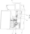
- Figure 1 can be seen the box-shaped body of the apparatus, which comprises an upper operating floor -1 in which are arranged the functional components of the apparatus and a lower floor -2- in which are arranged the containers for washing solutions, waste liquids and the collection of used cards, as well as the electronic control system of the apparatus and the fluidic control system intended particularly for the control of washing fluids.
- a folding touch screen -3-, with an articulated arm -3'-, allows the operator to interact with the apparatus by receiving information and entering instructions or functional requests.
- FIG. 1 various supports or drawers for reagents and samples are incorporated in the left part of the upper floor -1- of the apparatus.
- This drawing shows an example arrangement in which the supports -4- and -5- allow the housing of racks of reagents and diluents and a further two supports -6 and -7- are designed to house the sample receptacles.
- the apparatus is designed for interchangeability of the positions of the reagent, diluent or sample racks in any of the supports.
- the operator could have, for example, a single support for reagents and diluents and the others for samples, or alternatively could use two or three supports for reagents and diluents, bearing in mind that preferably two positions will be fitted with agitators intended for the vials of reagents.
- the apparatus has two heads -10- and -11- respectively for the perforation of tubes with stoppers and the pipetting of liquids and for the handling of the gel cards.
- Said heads are mounted on respective carriages -12- and -13- which can be moved in the longitudinal direction of the apparatus along guides that run in the upper part of the apparatus, which are not visible in Figure 1 and will be explained in more detail later.
- the heads -10-and -11- can be moved on transverse guides of the carriages -12- and -13-, in such a way that said heads can be moved without any impediment over any point of the upper floor in the zone corresponding to each head, i.e.
- the head -10- in the whole of the zone for racks of reagents, diluents and samples and in the card pipetting zone, and the head -11- over the gel card drawers, incubator, centrifuge filling windows and others, which will be explained.
- Figure 1 bis shows the tilting nature of the part -10'- of the upper floor intended for reagents, diluents and samples, as well as the dilution well.
- the tilting is achieved by means of hinges in its rear part, and allows easy access for maintenance, cleaning, etc.
- the front door of the apparatus can be opened as a whole, for example in a guillotine manner.
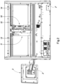
- Figure 2 shows a rear elevation view of the apparatus in which can be seen the heads -10- and -11- with their upper supporting carriages -12- and -13, as well as the upper longitudinal guide -14- along which the carriages -12- and -13- are moved.
- Figure 2 also shows the touch screen -3- which, by means of the articulated arm -3'-, can be positioned folded against one side of the apparatus or in the unfolded position, as shown in said Figure 2 .
- This latter position corresponds to the working position of the apparatus, in which the operator can interact with the screen.
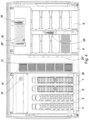
- Figure 3 can be seen the base of the upper floor -1-, with part of the components already described and also the set of incubators -14'- arranged between the reagent and sample zone and the gel card zone, in order to keep the cards at a controlled temperature.
- Figure 3 also shows the dilution well -15-, in which blood samples are diluted without any disposable items, and a support -16- for cards that have only been partially used, i.e. in which some of the wells have not yet been used.
- One of the features of the apparatus forming the subject of the present invention lies in the construction of the base or floor plate of the upper floor, in the part that corresponds to reagents, dilutions and samples, which is smooth and impermeable with respect to the assembly of mechanisms located beneath said floor plate, so as to avoid any possibility of contamination of mechanical and electric or electronic parts and simultaneously facilitate the cleaning of said floor plate.
- the apparatus forming the subject of the present invention is characterised by the magnetic interconnection between the motors located in the lower floor and the components intended to be driven in the upper floor.
- Said base or floor plate is also provided with magnetic elements for guiding and braking the supports or drawers carrying the racks of reagents and diluents, as well as those intended for supporting the sample receptacles. All of this will be explained in more detail below.
- Figure 4 bis shows a cross-section of the part corresponding to the cards, showing card holders -20'-that are held in the working position by the end lugs of the holder, which are retained, respectively, at one end by a flexible claw -9'- of the drawer and at the other end by a fixed lug -8'- of the fixed structure of the upper floor. This arrangement keeps the card holders stable in their housing and facilitates their handling.
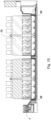
- FIG. 5 shows a plan view of the upper floor of the apparatus in which the right side, i.e. the side corresponding to the gel cards, has been represented schematically, with the floor removed.
- the arrangement of the centrifuges -21- and -22- which will be explained in more detail later.
- Said centrifuges are located beneath the floor plate of the zone intended for the gel cards, being arranged in separate closed containers provided with windows -23- and -24- for the insertion of the cards, which correspond to items -19- and -20- in Figure 4 .
- Figure 5bis represents the tilting arrangement of the right part of the upper floor, in a manner similar to that represented in Figure 1 bis for the left part.
- Figure 6 which shows a representative rear elevation view of the apparatus with the rear covers removed, can be seen the relative position of one of the centrifuges -21-, upper drawers for gel cards, dilution well -15-, and adjacent zone for the reagent, diluent and sample rack supports. Also visible in this view is the arrangement of the card reader -25-, in which a gel card -26- is shown schematically in the reading position.
- a zone -31- is intended to contain the electrical and electronic components of the apparatus.
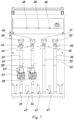
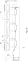
- Figure 7 shows a partial plan view of the zone of the upper floor that houses the reagent and diluent supports (-4-, -5-) and the sample supports (-6-, -7-).
- the base plate of the upper floor which in this figure has been represented with the number -32-, is provided with a series of longitudinal magnetic strips such as those indicated with the numbers -33-, -34-, -35- and -36-.
- the magnetic strips are composed of adjacent strips of different polarity which mate with other strips located in the bottom part of the respective reagent and diluent supports (-4-, -5-) and sample supports (-6-, -7-), as will be seen later in Figures 13 and 17 .
- each removable support for reagents and diluents or for samples
- the corresponding magnetic strips of the base plate -32- of the upper floor provides effective longitudinal guidance of each support within the upper floor when it is inserted, as well as providing braking for said support, avoiding vibrations in the containers of the different liquids arranged in the respective supports (for reagents and diluents or for samples).
- the magnetic-clutch motors -37- and -38- for agitating the supports of racks of reagents that must be shaken.
- Said motors -37- and -38- which are arranged beneath the plate -32-, allow, by means of magnetic coupling through said plate -32-, the agitation of the corresponding reagent racks without any possibility of liquid leaks.
- each reagent support and each sample support comprises a magnetic identifier that allows it to be correspondingly identified by the sensors -43-, -44-, -45- and -46- indicating the presence of one type of support or the other.
- sensors -37'- and -38'- for controlling the movement of the reagent racks actuated by the corresponding motors -37- and -38-.
- Said sensors function in combination with rotating portions of the respective reagent racks, making it possible to detect whether or not the corresponding reagent rack is actually rotating.
- the functioning of said sensors -37'- and -38'- in combination with said rotating portions of the respective reagent racks, as illustrated in Figure 14 will be explained in more detail later.
- the upper floor additionally comprises a system for detecting any improper intrusion of the user's hand or other similar object into any unoccupied cavity for reagent and/or sample supports during the operation of the apparatus forming the subject of the present invention.
- Said system comprises a plurality of infra-red emitters -48- located in the rear face of the upper floor and arranged in line with the spaces between the housings for each pair of adjacent reagent and/or sample racks.
- Said infra-red emitters -48- can also be seen in Figures 3 and 19 .
- the front part of the upper floor is provided with a plurality of infra-red ray reflectors -47-respectively in line with each infra-red emitter -48-, in such a way as to allow the detection of any unpermitted intrusion during the operation of the apparatus.
- An example of unpermitted intrusion would be the hand of a user who, during the operation of the apparatus, wishes to reach from the front part of the apparatus through an unoccupied cavity for reagent and/or sample supports and improperly accesses the containers of reagents, diluents and/or samples in adjacent reagent and/or sample supports.
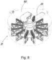
- FIGs 8 and 9 show a centrifuge, in the assembled position in Figure 8 and disassembled into its main components in Figure 9 .
- the centrifuge -21- has a practically closed structure, with a window -23-, as explained previously, for the insertion of gel cards into the centrifuge, and is provided with a turning motor -49-and a top cover -50-.
- a rotor -51- is attached to the motor -49-, and said rotor carries individual tilting supports for the different gel cards -52-, which are loaded from above through the window -23- and which will remain with the wells in an essentially horizontal position during the operation of the centrifuge.
- each of the centrifuges can house 12 cards.
- Figure 10 shows the lower floor -2- which contains the housings for the washing solutions and for waste liquids and scrap cards.
- housings for the washing solutions and for waste liquids and scrap cards.
- four identical housings -53-, -54-, -55- and -56- can be seen.
- solution A is for washing
- solution B is for rinsing.
- the user can choose between two combinations, in one of which there is a housing -53- for solution A and a housing -54-for solution B, with the housings -55- and -56- intended for waste.
- the housings -53-and -54- will be used for solution A and the housings -55-and -56 for solution B, with the provision in this case of an outlet -2'-, represented in Figure 2 , for conveying waste liquids to an external reservoir or drain.
- the four housings intended for liquids are identical to each other.
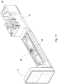
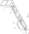
- Figures 11 , 12 and 13 show respectively a perspective view, top view and bottom view of a support for reagent and diluent racks.
- the support is indicated with the number -4-, which corresponds to the front handle.
- the support receives a first module or rack -59- of reagents, Figure 12 , which in the embodiment shown has 17 positions such as position -60-, said first rack -59- being intended for reagents that must be agitated, for which purpose it is combined with one of the motors (-37-, -38-) located beneath the base plate -32- of the upper floor, with magnetic coupling to produce the agitation.
- a second module -61- is intended for reagents that do not need to be agitated, and another housing -62-is intended to receive diluents.
- Figure 11 can be seen the same support for reagent and diluent racks with the module 61- for reagents that do not have to be agitated and the base -63- for the rack of reagents that must be agitated (not illustrated).
- Said base -63- is subject to the action of the eccentric mass 64, which in turn is subject to the action of one of the motors (-37-, -38-) with magnetic coupling, located beneath the plate -32- of the first floor as shown previously in Figure 7 .
- Figure 13 can be seen the lower part of the support for reagent racks, showing the linear magnetic strips -65- and -66- which work in combination with the corresponding linear magnetic strips -33-, -34- shown in Figure 7 . Additionally, the lower part of the support for reagent and diluent racks comprises an identifier -4'- for identifying the type of support.
- Said identifier 4'- is a magnetic element arranged in a specific zone in the lower part of the support in such a way that, when the reagent support is inserted into any one of the cavities for supports on the plate -32-, the respective sensors -43-, -44-, -45- and -46- explained previously in relation to Figure 7 allow the detection by magnetic coupling of the type of support inserted.
- Figure 14 shows a representative view of the overall positioning of the support for reagent racks, illustrating the vials -94- with the module for reagents that must be agitated -59- and the module -61- for reagents that do not have to be agitated, as well as the agitating eccentric mass -64- and the driven disc -67- for actuating said eccentric mass by means of magnetic coupling with one of the motors (-37-, -38-) arranged beneath the base of the upper floor.
- the disc -67- comprises a magnetic element -67'- arranged in an end zone of said disc -67-, which in combination with one of the sensors -37'- and -38'- arranged beneath the plate -32- makes it possible to detect whether or not said disc -67- is being moved by the action of the respective magnetic-clutch motor (-37-, -38-).
- the motors (-37-, -38-) with magnetic-clutch actuate by magnetic coupling the respective disc -67-, which in turn allows the orbital agitation of the eccentric mass -64- actuating the respective rack -59- of reagents to be agitated.
- the respective sensors -37'- and -38'- detect whether the element -67'- is also being agitated.
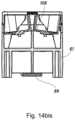
- the vials -94- are arranged at a certain angle relative to the vertical, which allows better pipetting.
- the cross-section view of Figure 14 bis illustrates the arrangement of the support, showing the inclination of the base -106- of each of the housings.
- Figures 15 and 16 show, by way of example, a support for racks of samples, with two racks in place.
- Said support is indicated with the number -7- for correspondence with Figure 1 , and in these figures it can be seen that the support is provided with two housings -68- and -69-, each for one rack of samples -70-, which in the illustrated example is intended to contain 12 tubes of samples.
- the supports are removable, in a manner similar to that described for the reagent supports, and are provided with a magnetic guidance and braking system and a system for detecting the type of rack, as well as a fastening system that will be explained in more detail later.
- Figure 17 shows a bottom view of the support for racks of samples, indicating the magnetic strip -71- which works in combination with the fixed magnetic strips, in a manner similar to that explained previously.
- the lower part of the support for sample racks comprises an identifier -7'- for identifying the type of support.
- Said identifier -7'- is a magnetic element arranged in a specific zone in the lower part of the support in such a way that, when the sample support is inserted into any one of the cavities for supports on the plate -32-, the respective sensors -43-, -44-, -45- and -46- explained previously in relation to Figure 7 allow the detection by magnetic coupling of the type of support inserted.
- the identifier -4'- of the support -4- for racks of reagents and diluents will have a location different from that of the identifier -7'- of the sample support -7-.
- Figures 18 and 18 bis show an incubator device -14'- that has multiple supports -72- for the gel cards -72'- and Peltier units -73- for the heating/cooling of the same, said supports -72- being incorporated into aluminium frames -74- with a structure similar to a U shape and a central arm -75- that allows easy heat transfer.
- Figure 19 shows the dilution well indicated previously with the number -15-.
- the well allows blood samples to be diluted without the use of disposable elements, since it is provided with an automatic post-dilution washing system which comprises a bowl -95- provided with a liquid inlet and outlet (not illustrated).
- the well has an orbital agitation system comprising an upper magnetic disc -15'-actuated by a magnetic-clutch motor -15"-, all located beneath the platform -76- that holds the well.
- Said rotating disc is provided with a position and rotation sensor.
- Figures 20 to 22 show a perforating and pipetting head in a perspective view, a front elevation view and a side elevation view.
- Said head -10- is intended to be suspended and guided by its upper part on a supporting frame of the apparatus by means of the carriage -12- represented in Figures 1 and 2 , which allows it to move in a transverse direction, and a longitudinal guide, which will be explained later.
- This allows optimisation of the space in the upper floor of the apparatus in which said head must work, so that said head can access the entire surface of its respective floor, without any dead or excluded zones.
- the head has a movable assembly -77- which moves on a vertical spindle with its own actuating motor, said movable assembly -77- being provided with an intermediate magnetic clutch -78-, which allows the disconnection of the lower part of the movable assembly carrying the hold-down plate unit -88-, and which has guide means for two concentric probes, namely one probe -80- intended for perforating the rubber stoppers of sample tubes and a second concentric probe -81- intended for pipetting.
- the probe -80- that perforates the rubber stopper of a sample tube is actuated, while said probe is pressed vertically by the hold-down plate unit -88- of said movable assembly -77-, and then the pipetting probe -81-is allowed to move, being moved by its upper end by its own means, generically indicated with the number -83-.
- the head incorporates a system for the identification of samples and reagents.
- both the perforating probe and the pipetting probe must be washed.
- a washing liquid is used, which is collected immediately after washing, without any discontinuity over time. This makes it unnecessary to have any storage space for the washing liquid, since the delivery of washing liquid and the aspiration of the same, immediately after it touches the probe and said probe has been washed, are carried out simultaneously.
- the washing unit 84 of the pipetting needle showing the couplings -85-and -86- for the inlet and outlet of the washing liquid.
- the hold-down plate unit -88- is incorporated the washing device of the perforating probe, which also receives washing liquid that is recovered immediately in a continuous circuit.
- One of the liquid couplings can be seen in Figure 20 , where it is indicated with the number -87-.
- the hold-down plate unit -88- has a lower housing that essentially mates in form with the stoppered head of the sample tube on which it must operate, and also has means for centring the gel card, since the head must also act on the gel cards in the pipetting operation, for which reason the hold-down plate unit -88- has two pairs of centring lugs -88'- (of which only one is visible in Figure 22 ), which make it possible to hold the gel card in place during the operations of insertion and removal of the probe, preventing any movement of said card.
- the pipetting probe -81- is associated with a capacitance level-detecting system and another system for detecting correct pipetting.
- the purpose of the level-detecting system is to determine the level of the fluid in the sample tube, in order to have a reference for the volume that must be removed for the analysis cycle.
- the correct pipetting detector is designed to control the pipetting in terms of fluidic control, indicating any pipetting errors produced by soiling or other factors.
- the perforating and pipetting head is also provided with a sample and reagent identification system with a laser proximity detector housed in the body -79-, which allows detection of the presence of sample tubes and vials/bottles of reagents/diluents in the drawers, being located in a fixed position in the base of the head.
- the head is also provided with a barcode reading system comprising a structure with vertically moving elements -89- and -90- in which are housed two barcode readers which, by means of mirrors, are capable of reading in opposite directions.
- the overall width of the structure allows it to be lowered with the head situated above a rack, in such a way that the beams of the barcode readers are directed at the tubes/vials/bottles.
- the perforating probe has the ability to perforate the rubber stopper of the sample tube and also to regulate the pressure between the interior of the tube and the atmosphere.
- the hold-down plate moves together with the perforating probe, supporting the tube while the probe is withdrawn and having, as indicated previously, means for washing the interior and exterior of the perforating probe.
- the hold-down plate and the perforating probe are moved by the action of a magnetic clutch mechanism, indicated with the number -78- in Figures 20 and 22 , which separates when the hold-down plate reaches the stoppered tube.
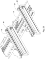
- Figure 23 shows the upper guides of the apparatus which allow the movements of the heads along the X and Y axes.
- the perforation and pipetting and card transport heads move along the respective carriages -12- and -13-, which have the respective transverse guides -91- and -92- along which the respective heads can move, driven by the corresponding motors and toothed belts or similar.
- the carriages -12- and -13- are movable along the longitudinal guide 14-, also shown in Figure 2 , which allows the movements of the heads along the other coordinate axis, allowing them to reach any point in the assigned zone.
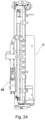
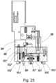
- the card-handling head -11- has a vertically movable unit -96- which is provided with elements for centring and clamping a gel card.
- Said unit -96- has two clamps opposite each other, of which only one clamp -97- is shown in Figure 25 .
- Said clamps are suitable for holding a gel card by its upper edges and are actuated by a magnetic device -98- incorporated in said unit -96-.
- a further pair of retractable arms -99- and -100- are suitable for centring the gel cards by their side edges, stabilising the same for the subsequent action of the holding clamps -97-.
- Said unit -96- has on its bottom surface -101- two pairs of end lugs, indicated with the numbers -102- and -103-, for centring the gel card, and also two pairs of retractable pointed pins -104- and -105- suitable for acting on the flat upper face of the gel card.
- a laser emitter/receiver -96'- which emits a beam through the channel -102'- and is intended to detect the surface of the cards in order to confirm that the clamp is holding a card, as well as serving the function of performing a mobile inventory of cards in the drawers, centrifuges and incubators. The beam returns to the emitter/receiver through the channel -101'-.
- the means with which the apparatus is provided allow it to operate automatically, offering numerous functional and security controls, notably the sample and reagent identification means comprised by both the perforating and pipetting head and the card transport head.
- the apparatus makes it possible, at the start of the work, for the apparatus to recognise each of the tubes, vials, bottles or cards individually, so that the electronic controller knows with precision the elements available for the work and their exact position.
- This information is updated for each movement carried out in the course of an analysis cycle, so that according to the analysis cycle to be conducted for each individual sample, the apparatus has the means for performing all the operations of the cycle, i.e.
- the apparatus has means for warning the operator accordingly and returning the card for visual inspection.
- the card will be removed and deposited in the scrap receptacle.
- the apparatus automatically places the card in a waiting zone, from where it will be automatically retrieved when use can be made of any of the unused wells for the performance of another analysis cycle.
- This way of proceeding helps to save on materials, has influence on the ecological general performance of the apparatus and makes it possible to reduce handling operations performed from the outside of the apparatus to the inside of the same for loading racks of cards, which in some machines were discarded after an analysis cycle regardless of the possibility of their partial recovery.
- the apparatus comprises: According to one aspect, a containing body with a flat upper functional floor for containing receptacles of reagents, diluents and samples, as well as housings for gel cards and incubators for the same; a lower floor containing receptacles for washing liquids and the collection of waste and cards and for housing the fluidic control and electronic control system; a series of longitudinal and transverse guides associated with the upper part of the apparatus, suitable for carrying in suspension the moving heads of the apparatus, said heads being movable on the transverse guides; two heads, respectively for perforation and pipetting and for the transport of gel cards; two centrifuges and a gel card reader; and a folding touch screen providing information and control.
- the base of the upper floor of the apparatus is made impermeable to liquids and has a flat overall structure in order to prevent liquids from reaching any electrical and electronic parts and to facilitate washing.
- the upper floor also has a zone intended to contain the supports for receptacles of samples, diluents and reagents, and another zone intended to contain the gel cards, said zones being separated by an intermediate zone occupied by the card incubators.
- the base of the upper floor is provided, in the zones that are to be occupied by the respective supports, with flat magnetic strips which combine with flat magnetic strips of mating polarity located in the base of the movable supports for said reagent, diluent and sample receptacles, providing linear magnetic guidance during the insertion and extraction of each of said supports and braking of the same on completion of their insertion, avoiding the need for mechanical guides for said supports.
- the supports for the reagent, diluent and sample receptacles comprise:
- the reagent receptacles are slightly inclined relative to the vertical.
- the bottoms of the housings for the reagent receptacles are slightly inclined, in order to impart an inclination to the receptacles.
- the upper floor is provided with a system of infra-red emitters in a bottom wall and sensors in a wall adjoining the front of the apparatus in order to detect any uncontrolled intrusions, triggering an alarm signal in the event of any such intrusion.
- the gel card centrifuge devices are coupled in suspension from the base of the upper floor of the apparatus beneath the card drawers, having an opening for each of said centrifuge devices that is accessible to the card-handling head through corresponding openings in the base of the upper floor of the apparatus.
- the incubators arranged between the reagent, diluent and sample zone and the card zone have multiple modules with slots for receiving cards and heating/cooling elements using Peltier cells, said modules being integrated by means of aluminium elements in contact with the Peltier cells and carriers of the card-receiving slots.
- Each of the supports for racks of sample tubes comprises a base containing two housings, each of these being intended to receive an individual rack for multiple sample tubes, said support having on its lower face longitudinal magnetic strips mating with the magnetic strips of the base of the upper floor for longitudinal guidance and braking of said support on completion of the insertion, said support also having a magnetic fastening which is automatically activated after the insertion of the support and can be deactivated via the touch screen.
- the system of guides for guiding the movements of the heads along two coordinate axes consists of a longitudinal guide attached to the top part of the apparatus, on which can move, driven by individual actuation means, respective carriages for the perforating and pipetting head and the card transport head, which are movable by their own actuation means on respective guides of said carriages, which are arranged transversely, so that together the heads can perform a bi-directional movement covering all the zones of the plane assigned to each of them.
- the head for perforating and pipetting reagent, diluent and sample tubes has an outer tubular probe provided with its own drive means, intended for perforating the rubber stoppers of the sample tubes, which contains within itself a pipetting probe that is actuated axially in an independent manner, making it possible to perform separately the perforation of the rubber stopper and the subsequent movement of the pipetting probe in order to detect the level of liquid in the receptacle and then to pipette said liquid.
- the pipetting probe is associated with means for detecting the level of liquid in the receptacle and with means for controlling the pipetting, said level-detecting means being a capacitance level-detecting device.
- the movable assembly of the perforating and pipetting head is provided with a magnetic clutch which allows the separation of the assembly when the hold-down plate reaches the sample tube.
- the perforating head has a hold-down plate unit suitable for pressing on the stopper of a sample tube during the operation of perforation and pipetting, and said hold-down plate unit also has projections shaped to mate with the upper edge of a gel card in order to immobilise said card when the pipetting is performed on it.
- Both the perforating and pipetting head and the card transport head have means for identifying individual vials of reagents, diluents and samples and cards, said receptacle identification means allowing a first step of identifying all the available receptacles in the upper floor of the apparatus, this information being incorporated into the central electronic controller for the purposes of performing a mobile inventory of each of the positions.
- the touch screen is arranged on a support with an articulated arm on one side of the apparatus, and can be unfolded for operational availability or folded up against the side of the apparatus, thus reducing the space occupied.
- the card transport head has a vertically movable unit carrying means for clamping and centring the card before and during its transport, comprising a laser detection system for detecting the presence of a card while it is transported by the clamp, as well as detecting the cards in the card drawers, incubators and centrifuges, situating the clamp at the corresponding height, two magnetically actuated clamps suitable for holding the gel card by the edges of its upper base and also having retractable means for prior centring, means for securing the gel card and fixed posts for centring the same, in such a way that the prior centring posts are retractable by means of a return spring and are suitable for adapting to the opposite sides of the upper base of the gel card prior to the actuation of the magnetic actuation posts for holding the card and the card securing means associated with the lower face of the movable unit of the head consist of pairs of retractable pointed pins suitable for acting on the upper face of the gel card being handled.
- the lower face has respective pairs of fixed posts near the ends of the
Landscapes
- Health & Medical Sciences (AREA)
- Life Sciences & Earth Sciences (AREA)
- Immunology (AREA)
- Chemical & Material Sciences (AREA)
- Analytical Chemistry (AREA)
- Biochemistry (AREA)
- General Health & Medical Sciences (AREA)
- General Physics & Mathematics (AREA)
- Pathology (AREA)
- Physics & Mathematics (AREA)
- Engineering & Computer Science (AREA)
- Biomedical Technology (AREA)
- Hematology (AREA)
- Molecular Biology (AREA)
- Urology & Nephrology (AREA)
- Chemical Kinetics & Catalysis (AREA)
- Biotechnology (AREA)
- Cell Biology (AREA)
- Microbiology (AREA)
- Food Science & Technology (AREA)
- Medicinal Chemistry (AREA)
- Automatic Analysis And Handling Materials Therefor (AREA)
- Sampling And Sample Adjustment (AREA)
- Centrifugal Separators (AREA)
Claims (28)
- Vorrichtung zur automatischen immunhämatologischen Analyse auf Gelkarten, die einen Aufnahmekörper umfassen, wobei der Aufnahmekörper umfasst:a) eine flache obere funktionalen Etage (1) mit Gefäßen für Reagenzien, Verdünnungsmittel und Proben sowie Schubladen (8, 9) für die Gelkarten (19, 20, 26, 52) und Inkubatoren (14') für die Gelkarten (19, 20, 26, 52);b) eine untere Ebene (2) mit Behältern (27, 28, 29, 30) zum Waschen von Flüssigkeiten und zum Sammeln von Abfallflüssigkeiten und ausrangierten Karten sowie zur Aufnahme eines fluidischen und elektronischen Steuersystems;c) zwei bewegliche Köpfe (10, 11), die in der oberen Etage untergebracht sind und jeweils zum Perforieren von Gummistopfen von Probenröhrchen und zum Pipettieren sowie zum Transportieren der Karten (19, 20, 26, 52) geeignet sind;d) eine Reihe von Längs- und Querführungen (91, 92), die mit dem oberen Teil der Vorrichtung verknüpft sind, geeignet zur Aufhängung der beweglichen Köpfe (10, 11) der Vorrichtung, die auf den Querführungen (91, 92) beweglich sind;e) zwei Zentrifugen (21, 22) und ein Gelkartenlesegerät (25); undf) einen faltbaren Informations- und Steuer-Touchscreen (3), wobei die obere funktionale Etage (1) mit einer einzelnen Arbeitsebene versehen ist, die auf einer ersten Seite Gefäße für Reagenzien und Verdünnungen, die Probenröhrchen und eine Verdünnungsvertiefung (15) hat, in einem Zentralbereich die Inkubatoren (14') hat, wobei der Dosierkopf (10) konfiguriert ist, jede Gelkarte (19, 20, 26, 52) zu dosieren, die in den Inkubatoren (14') vorhanden ist, und auf einer zweiten Seite die Kartenschubladen (8, 9), Zugänge zu Zentrifugen (21, 22), Zugang zum Kartenleser (25) und Zugang zur Aufnahme für ausrangierte Karten und zur vorübergehenden Aufbewahrung von Karten für ihre eventuelle Wiederverwendung hat.
- Vorrichtung nach Anspruch 1, bei dem eine Basis der oberen funktionalen Etage (1) der Vorrichtung flüssigkeitsundurchlässig ist und eine flache Gesamtstruktur aufweist, um zu verhindern, dass Flüssigkeiten an elektrische und elektronische Teile gelangen, und um ein Waschen zu erleichtern.
- Vorrichtung nach Anspruch 1, wobei die erste Seite der obere funktionalen Etage Stützen (6, 7) für Probenröhrchen und Stützen (4, 5) für Verdünnungsmittel und Reagenzien umfasst.
- Vorrichtung nach Anspruch 3, wobei zur linearen Führung und Abbremsung beim Fertigstellen des Einsetzens der Stützen für Reagenzien- und Verdünnungsgefäße (4, 5) und der Stützen (6, 7) für Probenröhrchen, die Basis der oberen funktionalen Etage (1) in den Bereichen, die von den jeweiligen Stützen eingenommen werden, mit flachen Magnetstreifen (33, 34, 35, 36) bereitgestellt wird, die sich mit flachen Magnetstreifen gleicher Polarität verbinden, die sich in der Basis der beweglichen Stützen für die Reagenzien- und Verdünnungsgefäße sowie für die Röhrchen befinden, wodurch eine lineare magnetische Führung während des Einsetzens und Herausziehens jeder dieser Stützen und ein Abbremsen derselben nach Abschluss ihres Einsetzens bereitgestellt wird, wodurch die Notwendigkeit mechanischer Führungen für diese Stützen vermieden wird.
- Vorrichtung nach Anspruch 3 oder 4, wobei der die Stützen (4, 5) für Reagenz- und Verdünnungsgefäße und die Stützen (6, 7) für Probenröhrchen folgendes aufweisen:- einen Bereich, der dazu bestimmt ist, eine Stütze für Reagenzgefäße aufzunehmen, und der Mittel zur Durchmischung aufweist,- einen Bereich zur Aufnahme einer Stütze für Reagenzgefäße, die nicht durchmischt werden müssen, und- einen weiteren Bereich, der zur Aufnahme von Verdünnungsaufnahmen bestimmt ist.
- Vorrichtung nach Anspruch 5, wobei die Reagenzgefäße gegenüber der Vertikalen leicht geneigt sind.
- Vorrichtung nach Anspruch 6, wobei die Stützen (4, 5) für Reagenzgefäße Gehäuse für die Reagenzgefäße aufweisen, deren Boden leicht geneigt ist, um den Reagenzgefäßen eine Neigung zu verleihen.
- Vorrichtung nach Anspruch 5, wobei jede Stütze für Reagenz- und Verdünnungsgefäße an ihrer unteren Basis mit Magnetstreifen ausgestattet ist, deren Polarität mit der des Bodens der Vorrichtung zusammenpasst, um eine magnetische Führung und Abbremsung der Stütze zu ermöglichen.
- Vorrichtung nach einem der Ansprüche 3 bis 8, wobei jede Stütze für Reagenzien- und Verdünnungsgefäße eine magnetische Befestigungsvorrichtung aufweist, die in der Position des maximalen Einsetzens der Stütze automatisch aktiviert wird und zu ihrer Deaktivierung Anweisungen des Touchscreens (3) benötigt, wodurch sie geöffnet werden kann.
- Vorrichtung nach Anspruch 1, wobei die obere funktionale Etage (1) mit einem System von Infrarotsendern (48) in einer unteren Wand und Sensoren (43, 44, 45, 46) in einer an die Front der Vorrichtung angrenzenden Wand bereitgestellt wird, um ein unkontrolliertes Eindringen zu detektieren, wobei im Falle eines solchen Eindringens ein Alarmsignal ausgelöst wird.
- Vorrichtung nach Anspruch 1, wobei die Zentrifugen (21, 22) an der Basis (32) der oberen funktionalen Etage (1) der Vorrichtung unterhalb der Kartenschubladen (8, 9) hängend verbunden sind, wobei jede der Zentrifugen eine Öffnung aufweist, die für den Kartentransportkopf (11) durch entsprechende Öffnungen in der Basis (32) der oberen funktionalen Etage (1) der Vorrichtung zugänglich ist.
- Vorrichtung nach Anspruch 1, wobei die zwischen dem Reagenz-, Verdünnungs- und Probenbereich und dem Kartenbereich angeordneten Inkubatoren (14') mehrere Module mit Schlitzen zum Aufnehmen von Karten Heiz-/Kühlelementen unter Verwendung von Peltier-Zellen (73) aufweisen, wobei die Module mittels Aluminiumelementen in Kontakt mit den Peltier-Zellen (73) und Trägern der Kartenaufnahmeschlitze integriert sind.
- Vorrichtung nach Anspruch 1, umfassend Stützen für Gestelle für Probenröhrchen, wobei jede der Stützen für Gestelle für Probenröhrchen eine Basis aufweist, die zwei Gehäuse aufweist, von denen jedes dazu bestimmt ist, ein einzelnes Gestell für mehrere Probenröhrchen aufzunehmen, wobei die Stütze auf ihrer Unterseite magnetische Längsstreifen aufweist, die mit den magnetischen Streifen der Basis der oberen Etage zusammenpassen, um die Stütze in Längsrichtung zu führen und nach Abschluss des Einsetzens abzubremsen, wobei die Stütze auch eine magnetische Befestigung aufweist, die nach dem Einsetzen der Stütze automatisch aktiviert wird und über den Touchscreen deaktiviert werden kann.
- Vorrichtung nach Anspruch 1, wobei das System der Führungen (91, 92) zur Führung der Bewegungen der Köpfe entlang zweier Koordinatenachsen aus einer am oberen Teil der Vorrichtung angebrachten Längsführung besteht, auf der sich angetrieben durch individuelle Betätigungsmittel die jeweiligen Schlitten (12, 13) für den Perforier- und Pipettier-Kopf (10) und den Kartentransportkopf (11) bewegen können, die durch ihre eigenen Betätigungsmittel auf den jeweiligen Führungen der Schlitten (12, 13), die quer angeordnet sind, beweglich sind, sodass die Köpfe (10, 11) zusammen eine bidirektionale Bewegung ausführen können, die alle Zonen der jedem von ihnen zugewiesenen Ebene abdeckt.
- Vorrichtung nach Anspruch 1, wobei der Kopf (10) zum Pipettieren und zum Perforieren von Gummistopfen von Probenröhrchen eine äußere rohrförmige Sonde (80) aufweist, die mit einem eigenen Antrieb versehen ist, der zum Perforieren der Gummistopfen der Probenröhrchen bestimmt ist und in seinem Inneren eine Pipettiersonde (81) enthält, die axial unabhängig betätigt wird, wodurch ermöglicht wird, das Perforieren des Gummistopfens und die anschließende Bewegung der Pipettiersonde (81) getrennt durchzuführen, um das Niveau der Flüssigkeit in dem Gefäß zu detektieren und dann diese Flüssigkeit zu pipettieren.
- Vorrichtung nach Anspruch 15, wobei die Pipettiersonde (81) mit Mitteln zum Detekteiren des Niveaus der Flüssigkeit in dem Gefäß und mit Mitteln zum Steuern des Pipettierens verknüpft ist.
- Vorrichtung nach Anspruch 15, wobei die Mittel zur Niveau-Detektion aus einer kapazitiven Niveau-Detektionsvorrichtung bestehen.
- Vorrichtung nach den Ansprüchen 1 und 15, wobei der Perforier- und Pipettierkopf eine Niederhalteplatte (88) und eine bewegliche Baugruppe (77) aufweist, wobei die bewegliche Baugruppe (77) mit einer Magnetkupplung (78) bereitgestellt wird, die die Trennung der Baugruppe (77) ermöglicht, wenn die Niederhalteplatte (88) das Probenröhrchen erreicht.
- Vorrichtung nach Anspruch 15, wobei der Perforierkopf (10) eine Niederhalteplatteneinheit (88) aufweist, die geeignet ist, während des Betriebs des Perforierens und Pipettierens auf den Stopfen eines Probenröhrchens zu drücken.
- Vorrichtung nach Anspruch 18, wobei die Niederhalteplatteneinheit (88) auch Vorsprünge aufweist, die so geformt sind, dass sie mit dem oberen Rand einer Gelkarte (19, 20, 26, 52) zusammenwirken, um die Karte (19, 20, 26, 52) zu fixieren, wenn das Pipettieren auf ihr durchgeführt wird.
- Vorrichtung nach Anspruch 1, wobei sowohl der Perforier- und Pipettierkopf (10) als auch der Kartentransportkopf (11) Mittel zur Identifizierung einzelner Reagenz-, Verdünnungs- und Probengefäße und Karten aufweisen.
- Vorrichtung nach Anspruch 21, wobei die Gefäßdetektiermittel in einem ersten Schritt die Identifizierung aller verfügbaren Gefäße in der oberen funktionalen Etage (1) der Vorrichtung ermöglichen, wobei diese Informationen in die zentrale elektronische Steuerung aufgenommen werden, um eine mobile Bestandsaufnahme jeder der Positionen durchzuführen.
- Vorrichtung nach Anspruch 1, wobei der Touchscreen (3) auf einer Stütze mit einem Gelenkarm (3') an einer Seite der Vorrichtung angeordnet ist und für die Betriebsverfügbarkeit ausgeklappt oder an der Seite der Vorrichtung eingeklappt werden kann, wodurch der Platzbedarf reduziert wird.
- Vorrichtung nach Anspruch 1, wobei der Kartentransportkopf (11) eine vertikal bewegliche Einheit (96) aufweist, die Mittel zum Einklemmen (97) und Zentrieren (99, 100) der Karte vor und während des Transports trägt, umfassend ein Laserdetektionssystem (96') zum Detektieren des Vorhandenseins einer Karte (19, 20, 26, 52) während des Transports durch die Klemme (97), sowie zum Detektieren der Karten (19, 20, 26, 52) in den Kartenschubladen (8, 9), die Inkubatoren (14') und Zentrifugen (21, 22) trägt, wobei die Klammer (97) in der entsprechenden Höhe angebracht wird, die zwei magnetisch betätigte Klammern trägt, die geeignet sind, die Gelkarte (19, 20, 26, 52) an den Rändern ihrer oberen Basis zu halten, und die außerdem einziehbare Mittel zur vorherigen Zentrierung (99, 100), Mittel zur Befestigung der Gelkarte (19, 20, 26, 52) und feste Laschen (102, 103) zur Zentrierung derselben trägt.
- Vorrichtung nach Anspruch 24, wobei die Vorzentrierzungszapfen (102, 103) mittels einer Rückholfeder einziehbar sind und geeignet sind, sich an die gegenüberliegenden Seiten der oberen Basis der Gelkarte (19, 20, 26, 52) vor der Betätigung der magnetischen Betätigungsstifte zum Halten der Karte anzupassen.
- Vorrichtung nach Anspruch 24, wobei die Kartenbefestigungsmittel, das mit der Unterseite der beweglichen Einheit (96) des Kopfes (11) verknüpft ist, aus Paaren von einziehbaren spitzen Stiften (104, 105) bestehen, die geeignet sind, auf die Oberseite der gehandhabten Gelkarte einzuwirken.
- Vorrichtung nach Anspruch 24, umfassend jeweilige Paare von festen Stiften (104, 105) in der Nähe der Enden der beweglichen Einheit (96) zum Zentrieren der Gelkarte an den Enden ihrer oberen Basis.
- Vorrichtung nach Anspruch 1, wobei die Kartenschubladen (8, 9) Kartengestelle enthalten und wobei die Kartengestelle in der Arbeitsposition durch die Endzapfen des Gestells gehalten werden, die jeweils an einem Ende durch eine flexible Klammer der Schublade und am anderen Ende durch einen festen Zapfen der festen Struktur der oberen Etage gehalten werden.
Applications Claiming Priority (1)
| Application Number | Priority Date | Filing Date | Title |
|---|---|---|---|
| ES201530927A ES2560110B1 (es) | 2015-06-26 | 2015-06-26 | Aparato para la realización automática de análisis de inmunohematología en tarjetas de gel |
Publications (2)
| Publication Number | Publication Date |
|---|---|
| EP3109641A1 EP3109641A1 (de) | 2016-12-28 |
| EP3109641B1 true EP3109641B1 (de) | 2023-07-26 |
Family
ID=55299810
Family Applications (1)
| Application Number | Title | Priority Date | Filing Date |
|---|---|---|---|
| EP16166497.4A Active EP3109641B1 (de) | 2015-06-26 | 2016-04-21 | Einrichtung zur automatischen untersuchung von proben auf gel cards |
Country Status (14)
| Country | Link |
|---|---|
| US (1) | US10107806B2 (de) |
| EP (1) | EP3109641B1 (de) |
| JP (1) | JP6491138B2 (de) |
| CN (1) | CN106290815B (de) |
| AR (1) | AR104526A1 (de) |
| AU (1) | AU2016202916B2 (de) |
| BR (1) | BR102016010809B1 (de) |
| CA (1) | CA2928845C (de) |
| CL (1) | CL2016001268A1 (de) |
| ES (2) | ES2560110B1 (de) |
| HU (1) | HUE063825T2 (de) |
| MX (1) | MX364959B (de) |
| PL (1) | PL3109641T3 (de) |
| PT (1) | PT3109641T (de) |
Families Citing this family (28)
| Publication number | Priority date | Publication date | Assignee | Title |
|---|---|---|---|---|
| DE202017002012U1 (de) * | 2016-05-17 | 2017-08-21 | Brand Gmbh + Co Kg | Gehäuse für ein Laborgerät |
| CN106546757A (zh) * | 2016-09-19 | 2017-03-29 | 嘉兴科瑞迪医疗器械有限公司 | 一种全自动血型分析仪 |
| CN106596987B (zh) * | 2016-12-17 | 2018-03-02 | 深圳市宇诺生物技术有限公司 | 一种适用于血型自动检测设备的血型卡移动及定位装置 |
| CN106959234B8 (zh) * | 2017-05-25 | 2024-03-12 | 烟台艾德康生物科技有限公司 | 一种血型检测卡打孔装置 |
| KR102199639B1 (ko) * | 2017-08-29 | 2021-01-07 | 가톨릭대학교 산학협력단 | 상이한 규격을 가진 래피드 키트들의 범용 판독 장치 |
| CN107831326B (zh) * | 2017-10-20 | 2024-07-02 | 厦门市波生生物技术有限公司 | 全自动化学发光免疫分析仪 |
| EP3701270B1 (de) * | 2017-10-23 | 2024-08-14 | F. Hoffmann-La Roche AG | Laborsystem zur automatischen verarbeitung biologischer proben, verwendung davon und verfahren zur verarbeitung biologischer proben mittels eines solchen laborsystems |
| ES2995478T3 (en) * | 2017-11-22 | 2025-02-10 | Grifols Diagnostic Solutions Inc | Systems and methods for biological sample laboratory screening |
| CN108031502B (zh) * | 2017-12-12 | 2021-03-12 | 迪瑞医疗科技股份有限公司 | 一种多功能试剂架 |
| JP1618169S (de) * | 2018-01-26 | 2018-11-19 | ||
| JP1630239S (de) * | 2018-07-27 | 2019-05-07 | ||
| US12313643B2 (en) | 2019-05-28 | 2025-05-27 | Roche Diagnostics Operations, Inc. | Reagent drawer and associated detector mounted to a slider capable of extending from an automatic analyzer housing |
| JP7453995B2 (ja) * | 2019-05-28 | 2024-03-21 | エフ. ホフマン-ラ ロシュ アーゲー | 自動分析装置 |
| CN110531069B (zh) * | 2019-08-09 | 2022-07-26 | 厦门市波生生物技术有限公司 | 一种分条多项联合免疫荧光层析检测系统 |
| CN110538679B (zh) * | 2019-08-19 | 2025-01-14 | 昆山汇先医药技术有限公司 | 一种微流控样品处理设备的机械臂移液系统 |
| JP7431534B2 (ja) * | 2019-08-23 | 2024-02-15 | シスメックス株式会社 | 試料処理装置、ホルダ、および試料測定システム |
| US12005432B2 (en) | 2019-10-10 | 2024-06-11 | Coopersurgical, Inc. | Configurable workstations |
| LU101493B1 (en) * | 2019-11-22 | 2021-05-26 | Stratec Se | Rack for automated analyzer |
| USD978369S1 (en) * | 2020-09-21 | 2023-02-14 | Cepheid | Diagnostic assay system |
| CN112206850A (zh) * | 2020-09-30 | 2021-01-12 | 苏州莱博睿思生物科技有限公司 | 一种样本收集装置 |
| CN112776072A (zh) * | 2020-12-27 | 2021-05-11 | 江苏贝索生物工程有限公司 | 一种全自动血型分析仪的凝胶卡打孔装置 |
| JP1718576S (ja) * | 2021-01-14 | 2022-06-29 | 試料処理機 | |
| US20220268796A1 (en) * | 2021-02-19 | 2022-08-25 | Roche Molecular Systems, Inc. | Method of Operating a Laboratory Instrument |
| LU103025B1 (en) * | 2022-09-27 | 2024-03-28 | Stratec Se | Drawer for bulk liquid supply |
| CN115814874A (zh) * | 2022-12-15 | 2023-03-21 | 北京雷奥顶峰生物科技有限责任公司 | 一种可变距移液装置 |
| LU103182B1 (en) * | 2023-08-08 | 2025-02-10 | Stratec Se | Modular sample rack |
| CN116984050B (zh) * | 2023-09-27 | 2023-12-26 | 中国人民解放军总医院第二医学中心 | 一种血气分析仪及其使用方法 |
| CN117563699A (zh) * | 2023-12-29 | 2024-02-20 | 深圳迎凯生物科技有限公司 | 样本架组件及医用分析设备 |
Citations (1)
| Publication number | Priority date | Publication date | Assignee | Title |
|---|---|---|---|---|
| US20150111198A1 (en) * | 2012-03-08 | 2015-04-23 | Bio-Rad Innovations | Medical analysis method |
Family Cites Families (31)
| Publication number | Priority date | Publication date | Assignee | Title |
|---|---|---|---|---|
| US5578269A (en) | 1993-06-11 | 1996-11-26 | Ortho Diagnostic Systems Inc. | Automated blood analysis system with an integral centrifuge |
| EP0629858A1 (de) * | 1993-06-16 | 1994-12-21 | Kabushiki Kaisha Nittec | Vorrichtung zur Probenvorbereitung |
| JP3348949B2 (ja) * | 1993-12-28 | 2002-11-20 | オリンパス光学工業株式会社 | 吸引吐出装置 |
| AU715627B2 (en) * | 1996-02-21 | 2000-02-03 | Biomerieux Vitek, Inc. | Automatic sample testing machine |
| JP3295014B2 (ja) * | 1997-03-19 | 2002-06-24 | 株式会社大日本精機 | 液体試料中の成分物質の自動抽出装置および液体試料中の成分物質の自動濃度測定装置 |
| FR2760844B1 (fr) * | 1997-03-17 | 1999-05-21 | Genethon Ii | Dispositif et procede d'analyse automatique d'echantillons sur gels |
| ES2150339B1 (es) * | 1997-07-30 | 2001-06-01 | Grifols Grupo Sa | "maquina universal para analisis clinicos". |
| CA2244397A1 (en) * | 1997-08-01 | 1999-02-01 | Mykola Myroslaw Yaremko | An automated blood analysis system |
| ES2252925T3 (es) * | 1999-05-14 | 2006-05-16 | F. Hoffmann-La Roche Ag | Sistema de analizador automatico. |
| JP2001074750A (ja) | 1999-09-07 | 2001-03-23 | Kyowa Medex Co Ltd | 恒温装置及びこれを用いた恒温ユニット |
| JP2002286728A (ja) | 2001-03-27 | 2002-10-03 | Sysmex Corp | 液体吸引装置およびそれを備えた液体分析装置 |
| US6571934B1 (en) * | 2001-11-14 | 2003-06-03 | Dade Behring Inc. | Bi-directional magnetic sample rack conveying system |
| JP3896983B2 (ja) | 2003-04-18 | 2007-03-22 | 松下電器産業株式会社 | 自動分析装置 |
| AU2006244476B2 (en) * | 2005-05-06 | 2011-09-29 | Instrumentation Laboratory Company | Telescoping closed-tube sampling assembly |
| JP4618001B2 (ja) | 2005-05-25 | 2011-01-26 | 株式会社安川電機 | 自動化学分析装置 |
| US7520164B1 (en) * | 2006-05-05 | 2009-04-21 | E.I. Spectra, Llc | Thin film particle sensor |
| US7560071B2 (en) * | 2006-03-29 | 2009-07-14 | Nichols Michael J | Instrument docking station for an automated testing system |
| JP2007303885A (ja) | 2006-05-09 | 2007-11-22 | Olympus Corp | 分析装置と侵入検知装置 |
| JP5198094B2 (ja) * | 2008-03-07 | 2013-05-15 | シスメックス株式会社 | 分析装置 |
| ES2371185B1 (es) * | 2008-05-30 | 2012-08-07 | Grifols, S.A. | Aparato para la realizacion automatica de analisis de muestras en tarjetas de gel. |
| FR2932273B1 (fr) * | 2008-06-06 | 2011-10-07 | Noviloire Sa | Pince adaptee pour saisir un support d'echantillons biologiques, ensemble d'un support echantillons biologiques et d'une pince adaptee pour le saisir, et automate de traitement et/ou d'analyse d'echantillons biologiques |
| US8658417B2 (en) * | 2009-09-15 | 2014-02-25 | Qiagen Gaithersburg, Inc. | Multiple-input analytical system |
| JP5880435B2 (ja) * | 2010-07-13 | 2016-03-09 | 株式会社湯山製作所 | 分注装置 |
| US9679317B2 (en) * | 2011-08-11 | 2017-06-13 | Aow Holdings, Llc | Mobile assay facility and method of using same to procure and assay precious metals |
| EP2589967A1 (de) | 2011-11-04 | 2013-05-08 | Roche Diagnostics GmbH | Laborprobenverteilungssystem und entsprechendes Betriebsverfahren |
| EP2713166B1 (de) * | 2012-10-01 | 2019-05-22 | Eppendorf Ag | Laborautomat und Verfahren zur automatischen Behandlung von Laborproben |
| EP2719461B8 (de) * | 2012-10-12 | 2023-08-16 | F. Hoffmann-La Roche AG | Pipettiereinheit und Verfahren zum Pipettieren einer Testflüssigkeit |
| US20140162374A1 (en) | 2012-12-11 | 2014-06-12 | Ortho-Clinical Diagnostics, Inc. | Method for holding multiple types of diagnostic test consumables in a random access single container |
| US9731847B2 (en) * | 2012-12-11 | 2017-08-15 | Ortho-Clinical Diagnostics, Inc. | Method for holding multiple types of diagnostic test consumables in a random access single container |
| AU2013202805B2 (en) * | 2013-03-14 | 2015-07-16 | Gen-Probe Incorporated | System and method for extending the capabilities of a diagnostic analyzer |
| CN104360089B (zh) * | 2014-11-05 | 2016-04-20 | 合肥天一生物技术研究所 | 一种全自动微柱凝胶卡检测仪 |
-
2015
- 2015-06-26 ES ES201530927A patent/ES2560110B1/es active Active
-
2016
- 2016-04-21 ES ES16166497T patent/ES2961132T3/es active Active
- 2016-04-21 HU HUE16166497A patent/HUE063825T2/hu unknown
- 2016-04-21 PL PL16166497.4T patent/PL3109641T3/pl unknown
- 2016-04-21 EP EP16166497.4A patent/EP3109641B1/de active Active
- 2016-04-21 PT PT161664974T patent/PT3109641T/pt unknown
- 2016-05-03 CA CA2928845A patent/CA2928845C/en active Active
- 2016-05-04 MX MX2016005802A patent/MX364959B/es active IP Right Grant
- 2016-05-05 AR ARP160101275A patent/AR104526A1/es active IP Right Grant
- 2016-05-06 US US15/148,994 patent/US10107806B2/en active Active
- 2016-05-06 AU AU2016202916A patent/AU2016202916B2/en active Active
- 2016-05-09 JP JP2016093689A patent/JP6491138B2/ja active Active
- 2016-05-12 BR BR102016010809-8A patent/BR102016010809B1/pt active IP Right Grant
- 2016-05-18 CN CN201610329927.9A patent/CN106290815B/zh active Active
- 2016-05-25 CL CL2016001268A patent/CL2016001268A1/es unknown
Patent Citations (1)
| Publication number | Priority date | Publication date | Assignee | Title |
|---|---|---|---|---|
| US20150111198A1 (en) * | 2012-03-08 | 2015-04-23 | Bio-Rad Innovations | Medical analysis method |
Also Published As
| Publication number | Publication date |
|---|---|
| CA2928845A1 (en) | 2016-12-26 |
| PT3109641T (pt) | 2023-11-03 |
| JP2017015691A (ja) | 2017-01-19 |
| HUE063825T2 (hu) | 2024-02-28 |
| CL2016001268A1 (es) | 2016-10-14 |
| ES2560110A1 (es) | 2016-02-17 |
| JP6491138B2 (ja) | 2019-03-27 |
| US10107806B2 (en) | 2018-10-23 |
| AU2016202916A1 (en) | 2017-01-19 |
| BR102016010809B1 (pt) | 2021-04-06 |
| US20170023561A1 (en) | 2017-01-26 |
| PL3109641T3 (pl) | 2024-04-08 |
| CN106290815B (zh) | 2020-06-16 |
| AU2016202916B2 (en) | 2019-08-15 |
| AR104526A1 (es) | 2017-07-26 |
| CN106290815A (zh) | 2017-01-04 |
| MX364959B (es) | 2019-05-15 |
| ES2961132T3 (es) | 2024-03-08 |
| BR102016010809A2 (pt) | 2017-11-07 |
| CA2928845C (en) | 2020-03-24 |
| ES2560110B1 (es) | 2016-09-09 |
| EP3109641A1 (de) | 2016-12-28 |
| MX2016005802A (es) | 2016-12-26 |
Similar Documents
| Publication | Publication Date | Title |
|---|---|---|
| CA2928845C (en) | Apparatus for the automatic performance of immunohaematology analysis on gel cards | |
| CA2662674C (en) | Apparatus for the automatic analysis of samples on gel cards | |
| CN109073669B (zh) | 自动化诊断分析仪和用于自动化诊断分析仪的操作的方法 | |
| JP6170511B2 (ja) | 細胞を調製するためのシステム、装置及びデバイス | |
| US7641855B2 (en) | System for automatically storing and reprocessing patient samples in an automatic clinical analyzer | |
| JP4712363B2 (ja) | 着脱自在なホルダ又は遠心機を備えた分析器 | |
| EP2743703B1 (de) | Verfahren zum Halten mehrerer Arten von Diagnosetestverbrauchsartikeln in einem einzelnen Direktzugriffsbehälter | |
| US9731847B2 (en) | Method for holding multiple types of diagnostic test consumables in a random access single container | |
| CA2244397A1 (en) | An automated blood analysis system | |
| EP3814778B1 (de) | Automatischer analysator | |
| HK1228511B (en) | Apparatus for the automatic performance of immunohematology analysis on gel cards | |
| HK1228511A1 (en) | Apparatus for the automatic performance of immunohematology analysis on gel cards | |
| HK1138639B (en) | Apparatus for the automatic analysis of samples on gel cards | |
| HK1201917B (en) | System, apparatuses and devices for pretreating cells |
Legal Events
| Date | Code | Title | Description |
|---|---|---|---|
| PUAI | Public reference made under article 153(3) epc to a published international application that has entered the european phase |
Free format text: ORIGINAL CODE: 0009012 |
|
| STAA | Information on the status of an ep patent application or granted ep patent |
Free format text: STATUS: THE APPLICATION HAS BEEN PUBLISHED |
|
| AK | Designated contracting states |
Kind code of ref document: A1 Designated state(s): AL AT BE BG CH CY CZ DE DK EE ES FI FR GB GR HR HU IE IS IT LI LT LU LV MC MK MT NL NO PL PT RO RS SE SI SK SM TR |
|
| AX | Request for extension of the european patent |
Extension state: BA ME |
|
| STAA | Information on the status of an ep patent application or granted ep patent |
Free format text: STATUS: REQUEST FOR EXAMINATION WAS MADE |
|
| 17P | Request for examination filed |
Effective date: 20170621 |
|
| RBV | Designated contracting states (corrected) |
Designated state(s): AL AT BE BG CH CY CZ DE DK EE ES FI FR GB GR HR HU IE IS IT LI LT LU LV MC MK MT NL NO PL PT RO RS SE SI SK SM TR |
|
| REG | Reference to a national code |
Ref country code: HK Ref legal event code: DE Ref document number: 1228511 Country of ref document: HK |
|
| STAA | Information on the status of an ep patent application or granted ep patent |
Free format text: STATUS: EXAMINATION IS IN PROGRESS |
|
| 17Q | First examination report despatched |
Effective date: 20210503 |
|
| GRAP | Despatch of communication of intention to grant a patent |
Free format text: ORIGINAL CODE: EPIDOSNIGR1 |
|
| STAA | Information on the status of an ep patent application or granted ep patent |
Free format text: STATUS: GRANT OF PATENT IS INTENDED |
|
| INTG | Intention to grant announced |
Effective date: 20230206 |
|
| GRAJ | Information related to disapproval of communication of intention to grant by the applicant or resumption of examination proceedings by the epo deleted |
Free format text: ORIGINAL CODE: EPIDOSDIGR1 |
|
| STAA | Information on the status of an ep patent application or granted ep patent |
Free format text: STATUS: EXAMINATION IS IN PROGRESS |
|
| INTC | Intention to grant announced (deleted) | ||
| GRAP | Despatch of communication of intention to grant a patent |
Free format text: ORIGINAL CODE: EPIDOSNIGR1 |
|
| STAA | Information on the status of an ep patent application or granted ep patent |
Free format text: STATUS: GRANT OF PATENT IS INTENDED |
|
| P01 | Opt-out of the competence of the unified patent court (upc) registered |
Effective date: 20230329 |
|
| GRAS | Grant fee paid |
Free format text: ORIGINAL CODE: EPIDOSNIGR3 |
|
| GRAA | (expected) grant |
Free format text: ORIGINAL CODE: 0009210 |
|
| STAA | Information on the status of an ep patent application or granted ep patent |
Free format text: STATUS: THE PATENT HAS BEEN GRANTED |
|
| INTG | Intention to grant announced |
Effective date: 20230605 |
|
| AK | Designated contracting states |
Kind code of ref document: B1 Designated state(s): AL AT BE BG CH CY CZ DE DK EE ES FI FR GB GR HR HU IE IS IT LI LT LU LV MC MK MT NL NO PL PT RO RS SE SI SK SM TR |
|
| REG | Reference to a national code |
Ref country code: GB Ref legal event code: FG4D |
|
| REG | Reference to a national code |
Ref country code: CH Ref legal event code: EP |
|
| REG | Reference to a national code |
Ref country code: IE Ref legal event code: FG4D |
|
| REG | Reference to a national code |
Ref country code: DE Ref legal event code: R096 Ref document number: 602016081294 Country of ref document: DE |
|
| REG | Reference to a national code |
Ref country code: NL Ref legal event code: FP |
|
| REG | Reference to a national code |
Ref country code: PT Ref legal event code: SC4A Ref document number: 3109641 Country of ref document: PT Date of ref document: 20231103 Kind code of ref document: T Free format text: AVAILABILITY OF NATIONAL TRANSLATION Effective date: 20231025 |
|
| REG | Reference to a national code |
Ref country code: LT Ref legal event code: MG9D |
|
| REG | Reference to a national code |
Ref country code: SE Ref legal event code: TRGR |
|
| REG | Reference to a national code |
Ref country code: AT Ref legal event code: MK05 Ref document number: 1592503 Country of ref document: AT Kind code of ref document: T Effective date: 20230726 |
|
| PG25 | Lapsed in a contracting state [announced via postgrant information from national office to epo] |
Ref country code: GR Free format text: LAPSE BECAUSE OF FAILURE TO SUBMIT A TRANSLATION OF THE DESCRIPTION OR TO PAY THE FEE WITHIN THE PRESCRIBED TIME-LIMIT Effective date: 20231027 |
|
| PG25 | Lapsed in a contracting state [announced via postgrant information from national office to epo] |
Ref country code: IS Free format text: LAPSE BECAUSE OF FAILURE TO SUBMIT A TRANSLATION OF THE DESCRIPTION OR TO PAY THE FEE WITHIN THE PRESCRIBED TIME-LIMIT Effective date: 20231126 |
|
| PG25 | Lapsed in a contracting state [announced via postgrant information from national office to epo] |
Ref country code: RS Free format text: LAPSE BECAUSE OF FAILURE TO SUBMIT A TRANSLATION OF THE DESCRIPTION OR TO PAY THE FEE WITHIN THE PRESCRIBED TIME-LIMIT Effective date: 20230726 Ref country code: NO Free format text: LAPSE BECAUSE OF FAILURE TO SUBMIT A TRANSLATION OF THE DESCRIPTION OR TO PAY THE FEE WITHIN THE PRESCRIBED TIME-LIMIT Effective date: 20231026 Ref country code: LV Free format text: LAPSE BECAUSE OF FAILURE TO SUBMIT A TRANSLATION OF THE DESCRIPTION OR TO PAY THE FEE WITHIN THE PRESCRIBED TIME-LIMIT Effective date: 20230726 Ref country code: LT Free format text: LAPSE BECAUSE OF FAILURE TO SUBMIT A TRANSLATION OF THE DESCRIPTION OR TO PAY THE FEE WITHIN THE PRESCRIBED TIME-LIMIT Effective date: 20230726 Ref country code: IS Free format text: LAPSE BECAUSE OF FAILURE TO SUBMIT A TRANSLATION OF THE DESCRIPTION OR TO PAY THE FEE WITHIN THE PRESCRIBED TIME-LIMIT Effective date: 20231126 Ref country code: HR Free format text: LAPSE BECAUSE OF FAILURE TO SUBMIT A TRANSLATION OF THE DESCRIPTION OR TO PAY THE FEE WITHIN THE PRESCRIBED TIME-LIMIT Effective date: 20230726 Ref country code: GR Free format text: LAPSE BECAUSE OF FAILURE TO SUBMIT A TRANSLATION OF THE DESCRIPTION OR TO PAY THE FEE WITHIN THE PRESCRIBED TIME-LIMIT Effective date: 20231027 Ref country code: FI Free format text: LAPSE BECAUSE OF FAILURE TO SUBMIT A TRANSLATION OF THE DESCRIPTION OR TO PAY THE FEE WITHIN THE PRESCRIBED TIME-LIMIT Effective date: 20230726 Ref country code: AT Free format text: LAPSE BECAUSE OF FAILURE TO SUBMIT A TRANSLATION OF THE DESCRIPTION OR TO PAY THE FEE WITHIN THE PRESCRIBED TIME-LIMIT Effective date: 20230726 |
|
| REG | Reference to a national code |
Ref country code: HU Ref legal event code: AG4A Ref document number: E063825 Country of ref document: HU |
|
| REG | Reference to a national code |
Ref country code: ES Ref legal event code: FG2A Ref document number: 2961132 Country of ref document: ES Kind code of ref document: T3 Effective date: 20240308 |
|
| REG | Reference to a national code |
Ref country code: DE Ref legal event code: R097 Ref document number: 602016081294 Country of ref document: DE |
|
| PG25 | Lapsed in a contracting state [announced via postgrant information from national office to epo] |
Ref country code: SM Free format text: LAPSE BECAUSE OF FAILURE TO SUBMIT A TRANSLATION OF THE DESCRIPTION OR TO PAY THE FEE WITHIN THE PRESCRIBED TIME-LIMIT Effective date: 20230726 Ref country code: RO Free format text: LAPSE BECAUSE OF FAILURE TO SUBMIT A TRANSLATION OF THE DESCRIPTION OR TO PAY THE FEE WITHIN THE PRESCRIBED TIME-LIMIT Effective date: 20230726 Ref country code: EE Free format text: LAPSE BECAUSE OF FAILURE TO SUBMIT A TRANSLATION OF THE DESCRIPTION OR TO PAY THE FEE WITHIN THE PRESCRIBED TIME-LIMIT Effective date: 20230726 Ref country code: DK Free format text: LAPSE BECAUSE OF FAILURE TO SUBMIT A TRANSLATION OF THE DESCRIPTION OR TO PAY THE FEE WITHIN THE PRESCRIBED TIME-LIMIT Effective date: 20230726 Ref country code: CZ Free format text: LAPSE BECAUSE OF FAILURE TO SUBMIT A TRANSLATION OF THE DESCRIPTION OR TO PAY THE FEE WITHIN THE PRESCRIBED TIME-LIMIT Effective date: 20230726 Ref country code: SK Free format text: LAPSE BECAUSE OF FAILURE TO SUBMIT A TRANSLATION OF THE DESCRIPTION OR TO PAY THE FEE WITHIN THE PRESCRIBED TIME-LIMIT Effective date: 20230726 |
|
| PLBE | No opposition filed within time limit |
Free format text: ORIGINAL CODE: 0009261 |
|
| STAA | Information on the status of an ep patent application or granted ep patent |
Free format text: STATUS: NO OPPOSITION FILED WITHIN TIME LIMIT |
|
| 26N | No opposition filed |
Effective date: 20240429 |
|
| PG25 | Lapsed in a contracting state [announced via postgrant information from national office to epo] |
Ref country code: SI Free format text: LAPSE BECAUSE OF FAILURE TO SUBMIT A TRANSLATION OF THE DESCRIPTION OR TO PAY THE FEE WITHIN THE PRESCRIBED TIME-LIMIT Effective date: 20230726 |
|
| PG25 | Lapsed in a contracting state [announced via postgrant information from national office to epo] |
Ref country code: BG Free format text: LAPSE BECAUSE OF FAILURE TO SUBMIT A TRANSLATION OF THE DESCRIPTION OR TO PAY THE FEE WITHIN THE PRESCRIBED TIME-LIMIT Effective date: 20230726 |
|
| PG25 | Lapsed in a contracting state [announced via postgrant information from national office to epo] |
Ref country code: MC Free format text: LAPSE BECAUSE OF FAILURE TO SUBMIT A TRANSLATION OF THE DESCRIPTION OR TO PAY THE FEE WITHIN THE PRESCRIBED TIME-LIMIT Effective date: 20230726 |
|
| PG25 | Lapsed in a contracting state [announced via postgrant information from national office to epo] |
Ref country code: MC Free format text: LAPSE BECAUSE OF FAILURE TO SUBMIT A TRANSLATION OF THE DESCRIPTION OR TO PAY THE FEE WITHIN THE PRESCRIBED TIME-LIMIT Effective date: 20230726 Ref country code: BG Free format text: LAPSE BECAUSE OF FAILURE TO SUBMIT A TRANSLATION OF THE DESCRIPTION OR TO PAY THE FEE WITHIN THE PRESCRIBED TIME-LIMIT Effective date: 20230726 |
|
| PG25 | Lapsed in a contracting state [announced via postgrant information from national office to epo] |
Ref country code: LU Free format text: LAPSE BECAUSE OF NON-PAYMENT OF DUE FEES Effective date: 20240421 |
|
| PG25 | Lapsed in a contracting state [announced via postgrant information from national office to epo] |
Ref country code: LU Free format text: LAPSE BECAUSE OF NON-PAYMENT OF DUE FEES Effective date: 20240421 |
|
| PGFP | Annual fee paid to national office [announced via postgrant information from national office to epo] |
Ref country code: NL Payment date: 20250427 Year of fee payment: 10 |
|
| PGFP | Annual fee paid to national office [announced via postgrant information from national office to epo] |
Ref country code: PL Payment date: 20250408 Year of fee payment: 10 Ref country code: DE Payment date: 20250429 Year of fee payment: 10 |
|
| PGFP | Annual fee paid to national office [announced via postgrant information from national office to epo] |
Ref country code: GB Payment date: 20250428 Year of fee payment: 10 Ref country code: ES Payment date: 20250505 Year of fee payment: 10 |
|
| PGFP | Annual fee paid to national office [announced via postgrant information from national office to epo] |
Ref country code: HU Payment date: 20250422 Year of fee payment: 10 |
|
| PGFP | Annual fee paid to national office [announced via postgrant information from national office to epo] |
Ref country code: BE Payment date: 20250428 Year of fee payment: 10 Ref country code: IT Payment date: 20250422 Year of fee payment: 10 |
|
| PGFP | Annual fee paid to national office [announced via postgrant information from national office to epo] |
Ref country code: PT Payment date: 20250402 Year of fee payment: 10 |
|
| PGFP | Annual fee paid to national office [announced via postgrant information from national office to epo] |
Ref country code: FR Payment date: 20250425 Year of fee payment: 10 |
|
| PGFP | Annual fee paid to national office [announced via postgrant information from national office to epo] |
Ref country code: CH Payment date: 20250501 Year of fee payment: 10 |
|
| PGFP | Annual fee paid to national office [announced via postgrant information from national office to epo] |
Ref country code: TR Payment date: 20250418 Year of fee payment: 10 |
|
| PGFP | Annual fee paid to national office [announced via postgrant information from national office to epo] |
Ref country code: IE Payment date: 20250428 Year of fee payment: 10 |
|
| PGFP | Annual fee paid to national office [announced via postgrant information from national office to epo] |
Ref country code: SE Payment date: 20250430 Year of fee payment: 10 |
|
| PG25 | Lapsed in a contracting state [announced via postgrant information from national office to epo] |
Ref country code: CY Free format text: LAPSE BECAUSE OF FAILURE TO SUBMIT A TRANSLATION OF THE DESCRIPTION OR TO PAY THE FEE WITHIN THE PRESCRIBED TIME-LIMIT; INVALID AB INITIO Effective date: 20160421 |
|
| REG | Reference to a national code |
Ref country code: CH Ref legal event code: U11 Free format text: ST27 STATUS EVENT CODE: U-0-0-U10-U11 (AS PROVIDED BY THE NATIONAL OFFICE) Effective date: 20260501 |