EP3109572B1 - Réfrigérateur - Google Patents
Réfrigérateur Download PDFInfo
- Publication number
- EP3109572B1 EP3109572B1 EP16172645.0A EP16172645A EP3109572B1 EP 3109572 B1 EP3109572 B1 EP 3109572B1 EP 16172645 A EP16172645 A EP 16172645A EP 3109572 B1 EP3109572 B1 EP 3109572B1
- Authority
- EP
- European Patent Office
- Prior art keywords
- evaporator
- pipe
- refrigerant
- valve unit
- condenser
- Prior art date
- Legal status (The legal status is an assumption and is not a legal conclusion. Google has not performed a legal analysis and makes no representation as to the accuracy of the status listed.)
- Active
Links
Images


Classifications
-
- F—MECHANICAL ENGINEERING; LIGHTING; HEATING; WEAPONS; BLASTING
- F25—REFRIGERATION OR COOLING; COMBINED HEATING AND REFRIGERATION SYSTEMS; HEAT PUMP SYSTEMS; MANUFACTURE OR STORAGE OF ICE; LIQUEFACTION SOLIDIFICATION OF GASES
- F25B—REFRIGERATION MACHINES, PLANTS OR SYSTEMS; COMBINED HEATING AND REFRIGERATION SYSTEMS; HEAT PUMP SYSTEMS
- F25B47/00—Arrangements for preventing or removing deposits or corrosion, not provided for in another subclass
- F25B47/02—Defrosting cycles
- F25B47/022—Defrosting cycles hot gas defrosting
- F25B47/025—Defrosting cycles hot gas defrosting by reversing the cycle
-
- F—MECHANICAL ENGINEERING; LIGHTING; HEATING; WEAPONS; BLASTING
- F25—REFRIGERATION OR COOLING; COMBINED HEATING AND REFRIGERATION SYSTEMS; HEAT PUMP SYSTEMS; MANUFACTURE OR STORAGE OF ICE; LIQUEFACTION SOLIDIFICATION OF GASES
- F25B—REFRIGERATION MACHINES, PLANTS OR SYSTEMS; COMBINED HEATING AND REFRIGERATION SYSTEMS; HEAT PUMP SYSTEMS
- F25B39/00—Evaporators; Condensers
-
- F—MECHANICAL ENGINEERING; LIGHTING; HEATING; WEAPONS; BLASTING
- F25—REFRIGERATION OR COOLING; COMBINED HEATING AND REFRIGERATION SYSTEMS; HEAT PUMP SYSTEMS; MANUFACTURE OR STORAGE OF ICE; LIQUEFACTION SOLIDIFICATION OF GASES
- F25B—REFRIGERATION MACHINES, PLANTS OR SYSTEMS; COMBINED HEATING AND REFRIGERATION SYSTEMS; HEAT PUMP SYSTEMS
- F25B41/00—Fluid-circulation arrangements
- F25B41/20—Disposition of valves, e.g. of on-off valves or flow control valves
-
- F—MECHANICAL ENGINEERING; LIGHTING; HEATING; WEAPONS; BLASTING
- F25—REFRIGERATION OR COOLING; COMBINED HEATING AND REFRIGERATION SYSTEMS; HEAT PUMP SYSTEMS; MANUFACTURE OR STORAGE OF ICE; LIQUEFACTION SOLIDIFICATION OF GASES
- F25B—REFRIGERATION MACHINES, PLANTS OR SYSTEMS; COMBINED HEATING AND REFRIGERATION SYSTEMS; HEAT PUMP SYSTEMS
- F25B41/00—Fluid-circulation arrangements
- F25B41/30—Expansion means; Dispositions thereof
- F25B41/385—Dispositions with two or more expansion means arranged in parallel on a refrigerant line leading to the same evaporator
-
- F—MECHANICAL ENGINEERING; LIGHTING; HEATING; WEAPONS; BLASTING
- F25—REFRIGERATION OR COOLING; COMBINED HEATING AND REFRIGERATION SYSTEMS; HEAT PUMP SYSTEMS; MANUFACTURE OR STORAGE OF ICE; LIQUEFACTION SOLIDIFICATION OF GASES
- F25D—REFRIGERATORS; COLD ROOMS; ICE-BOXES; COOLING OR FREEZING APPARATUS NOT OTHERWISE PROVIDED FOR
- F25D11/00—Self-contained movable devices, e.g. domestic refrigerators
- F25D11/02—Self-contained movable devices, e.g. domestic refrigerators with cooling compartments at different temperatures
-
- F—MECHANICAL ENGINEERING; LIGHTING; HEATING; WEAPONS; BLASTING
- F25—REFRIGERATION OR COOLING; COMBINED HEATING AND REFRIGERATION SYSTEMS; HEAT PUMP SYSTEMS; MANUFACTURE OR STORAGE OF ICE; LIQUEFACTION SOLIDIFICATION OF GASES
- F25D—REFRIGERATORS; COLD ROOMS; ICE-BOXES; COOLING OR FREEZING APPARATUS NOT OTHERWISE PROVIDED FOR
- F25D21/00—Defrosting; Preventing frosting; Removing condensed or defrost water
- F25D21/14—Collecting or removing condensed and defrost water; Drip trays
-
- F—MECHANICAL ENGINEERING; LIGHTING; HEATING; WEAPONS; BLASTING
- F25—REFRIGERATION OR COOLING; COMBINED HEATING AND REFRIGERATION SYSTEMS; HEAT PUMP SYSTEMS; MANUFACTURE OR STORAGE OF ICE; LIQUEFACTION SOLIDIFICATION OF GASES
- F25D—REFRIGERATORS; COLD ROOMS; ICE-BOXES; COOLING OR FREEZING APPARATUS NOT OTHERWISE PROVIDED FOR
- F25D23/00—General constructional features
- F25D23/006—General constructional features for mounting refrigerating machinery components
-
- F—MECHANICAL ENGINEERING; LIGHTING; HEATING; WEAPONS; BLASTING
- F28—HEAT EXCHANGE IN GENERAL
- F28D—HEAT-EXCHANGE APPARATUS, NOT PROVIDED FOR IN ANOTHER SUBCLASS, IN WHICH THE HEAT-EXCHANGE MEDIA DO NOT COME INTO DIRECT CONTACT
- F28D1/00—Heat-exchange apparatus having stationary conduit assemblies for one heat-exchange medium only, the media being in contact with different sides of the conduit wall, in which the other heat-exchange medium is a large body of fluid, e.g. domestic or motor car radiators
- F28D1/02—Heat-exchange apparatus having stationary conduit assemblies for one heat-exchange medium only, the media being in contact with different sides of the conduit wall, in which the other heat-exchange medium is a large body of fluid, e.g. domestic or motor car radiators with heat-exchange conduits immersed in the body of fluid
- F28D1/04—Heat-exchange apparatus having stationary conduit assemblies for one heat-exchange medium only, the media being in contact with different sides of the conduit wall, in which the other heat-exchange medium is a large body of fluid, e.g. domestic or motor car radiators with heat-exchange conduits immersed in the body of fluid with tubular conduits
- F28D1/047—Heat-exchange apparatus having stationary conduit assemblies for one heat-exchange medium only, the media being in contact with different sides of the conduit wall, in which the other heat-exchange medium is a large body of fluid, e.g. domestic or motor car radiators with heat-exchange conduits immersed in the body of fluid with tubular conduits the conduits being bent, e.g. in a serpentine or zig-zag
- F28D1/0477—Heat-exchange apparatus having stationary conduit assemblies for one heat-exchange medium only, the media being in contact with different sides of the conduit wall, in which the other heat-exchange medium is a large body of fluid, e.g. domestic or motor car radiators with heat-exchange conduits immersed in the body of fluid with tubular conduits the conduits being bent, e.g. in a serpentine or zig-zag the conduits being bent in a serpentine or zig-zag
-
- F—MECHANICAL ENGINEERING; LIGHTING; HEATING; WEAPONS; BLASTING
- F28—HEAT EXCHANGE IN GENERAL
- F28F—DETAILS OF HEAT-EXCHANGE AND HEAT-TRANSFER APPARATUS, OF GENERAL APPLICATION
- F28F1/00—Tubular elements; Assemblies of tubular elements
- F28F1/10—Tubular elements and assemblies thereof with means for increasing heat-transfer area, e.g. with fins, with projections, with recesses
- F28F1/12—Tubular elements and assemblies thereof with means for increasing heat-transfer area, e.g. with fins, with projections, with recesses the means being only outside the tubular element
- F28F1/24—Tubular elements and assemblies thereof with means for increasing heat-transfer area, e.g. with fins, with projections, with recesses the means being only outside the tubular element and extending transversely
- F28F1/32—Tubular elements and assemblies thereof with means for increasing heat-transfer area, e.g. with fins, with projections, with recesses the means being only outside the tubular element and extending transversely the means having portions engaging further tubular elements
- F28F1/325—Fins with openings
-
- F—MECHANICAL ENGINEERING; LIGHTING; HEATING; WEAPONS; BLASTING
- F28—HEAT EXCHANGE IN GENERAL
- F28F—DETAILS OF HEAT-EXCHANGE AND HEAT-TRANSFER APPARATUS, OF GENERAL APPLICATION
- F28F9/00—Casings; Header boxes; Auxiliary supports for elements; Auxiliary members within casings
- F28F9/007—Auxiliary supports for elements
- F28F9/013—Auxiliary supports for elements for tubes or tube-assemblies
- F28F9/0131—Auxiliary supports for elements for tubes or tube-assemblies formed by plates
-
- F—MECHANICAL ENGINEERING; LIGHTING; HEATING; WEAPONS; BLASTING
- F25—REFRIGERATION OR COOLING; COMBINED HEATING AND REFRIGERATION SYSTEMS; HEAT PUMP SYSTEMS; MANUFACTURE OR STORAGE OF ICE; LIQUEFACTION SOLIDIFICATION OF GASES
- F25B—REFRIGERATION MACHINES, PLANTS OR SYSTEMS; COMBINED HEATING AND REFRIGERATION SYSTEMS; HEAT PUMP SYSTEMS
- F25B39/00—Evaporators; Condensers
- F25B39/02—Evaporators
-
- F—MECHANICAL ENGINEERING; LIGHTING; HEATING; WEAPONS; BLASTING
- F25—REFRIGERATION OR COOLING; COMBINED HEATING AND REFRIGERATION SYSTEMS; HEAT PUMP SYSTEMS; MANUFACTURE OR STORAGE OF ICE; LIQUEFACTION SOLIDIFICATION OF GASES
- F25D—REFRIGERATORS; COLD ROOMS; ICE-BOXES; COOLING OR FREEZING APPARATUS NOT OTHERWISE PROVIDED FOR
- F25D2321/00—Details or arrangements for defrosting; Preventing frosting; Removing condensed or defrost water, not provided for in other groups of this subclass
- F25D2321/14—Collecting condense or defrost water; Removing condense or defrost water
- F25D2321/144—Collecting condense or defrost water; Removing condense or defrost water characterised by the construction of drip water collection pans
- F25D2321/1441—Collecting condense or defrost water; Removing condense or defrost water characterised by the construction of drip water collection pans inside a refrigerator
Definitions
- This application relates to a refrigerator.
- a refrigerator has a plurality of storage compartments which accommodate stored goods and keep food refrigerated or frozen, and one surface of each of the storage compartments is formed to be opened, such that the food is accommodated or taken out therethrough.
- the plurality of storage compartments includes a freezer compartment in which the food is kept frozen, and a refrigerator compartment in which the food is kept refrigerated.
- a refrigeration system in which a refrigerant is circulated is driven in the refrigerator.
- the refrigeration system includes a compressor, a condenser, an expander and an evaporator. Cooling air stored in the freezer compartment is cooled while passing through the evaporator, and then supplied again into the freezer compartment, and at least some of the cooled cooling air may be supplied into the refrigerator compartment.
- DD 288 207 A5 a refrigerator according to the preamble of claim 1 is disclosed.
- US 3 213 637 A and US 4 215 555 A further describe related technology.
- the present disclosure is directed to a refrigerator that is able to perform a defrosting operation of an evaporator using a high temperature refrigerant.
- FIGS. 1-3 illustrate example refrigerators.
- FIG. 4 illustrates an A portion of FIG. 3 .
- FIG. 5 illustrates a B portion of FIG. 3 .
- a refrigerator 10 includes a cabinet 11 which forms a storage compartment.
- the storage compartment includes a refrigerator compartment 20 and a freezer compartment 30.
- the refrigerator compartment 20 may be disposed at an upper side of the freezer compartment 30.
- positions of the refrigerator compartment 20 and the freezer compartment 30 are not limited thereto.
- the refrigerator compartment 20 and the freezer compartment 30 may be divided by a partition wall 28.
- the refrigerator 10 includes a refrigerator compartment door 25 which opens and closes the refrigerator compartment 20 and a freezer compartment door 35 which opens and closes the freezer compartment 30.
- the refrigerator compartment door 25 may be hinge-coupled to a front of the cabinet 11 and may be formed to be rotatable, and the freezer compartment door 35 may be formed in a drawer type to be withdrawn forward.
- a direction is defined. Based on the cabinet 11 of FIG. 1 , a direction at which the refrigerator compartment door 25 is located is defined as a "front side”, and an opposite direction thereof is defined as a “rear side”, and a direction toward a side surface of the cabinet 11 is defined as a "lateral side”.
- the cabinet 11 includes an outer case 12 which forms an exterior of the refrigerator 10, and an inner case 13 which is disposed inside the outer case 12 and forms at least a part of an inner surface of the refrigerator compartment 20 or the freezer compartment 30.
- the inner case 13 includes a refrigerator compartment side inner case which forms the inner surface of the refrigerator compartment 20, and a freezer compartment side inner case which forms the inner surface of the freezer compartment 30.
- a panel 15 is provided at a rear surface of the refrigerator compartment 20.
- the panel 15 may be installed at a position which is spaced forward from a rear of the refrigerator compartment side inner case.
- a refrigerator compartment cooling air discharge part 22 for discharging cooling air to the refrigerator compartment 20 is provided at the panel 15.
- the refrigerator compartment cooling air discharge part 22 may be formed of a duct, and may be disposed to be coupled to an approximately central portion of the panel 15.
- a freezer compartment side panel may be installed at a rear wall of the freezer compartment 30, and a freezer compartment cooling air discharge part for discharging the cooling air to the freezer compartment 30 may be formed at the freezer compartment side panel.
- An installation space in which an evaporator 150 is installed may be formed at a space between the freezer compartment side panel and a rear portion of the freezer compartment side inner case.
- the refrigerator 10 includes the evaporator 150 which cools each of the refrigerator compartment 20 and the freezer compartment 30.
- the evaporator 150 is disposed at a rear of the freezer compartment 30, and the cooling air generated from the evaporator 150 may be supplied into each of the refrigerator compartment 20 and the freezer compartment 30 through the refrigerator compartment cooling air discharge part 22 and the freezer compartment cooling air discharge part.
- the evaporator 150 may be hooked to the inner case 13.
- the evaporator 150 includes hooks 162 and 167 (referring to FIG. 6 ) which are hooked to the inner case 13.
- the refrigerator 10 includes a plurality of devices for driving a refrigeration cycle.
- the refrigerator 10 includes a compressor 101 which compresses a refrigerant, a condenser 102 which condenses the refrigerant compressed by the compressor 101, a plurality of expanders 105 and 106 which depressurize the refrigerant, and the evaporator 150 which evaporates the refrigerant.
- the refrigerator 10 further includes a refrigerant pipe 100a which connects the compressor 101, the condenser 102, the expanders 105 and 106 and the evaporator 150 and guides a flow of the refrigerant.
- the plurality of expanders 105 and 106 include a first expander 105 for expanding the refrigerant which will be introduced into the evaporator 150 in a first operation mode (a cooling mode) of the refrigerator 10, and a second expander 106 for expanding the refrigerant which will be introduced into the condenser 102 in a second operation mode (a defrosting mode) of the refrigerator 10.
- Each of the first and second expanders 105 and 106 include a capillary tube.
- the first expander 105 is installed at an evaporator inlet pipe 197 installed at an inlet side of the evaporator 150. It is understood that the evaporator inlet pipe 197 is a pipe which extends from a second valve unit 130 to the evaporator 150. And the second expander 106 is installed at a second connection path 184.
- the refrigerator 10 further includes a first valve unit 120 which is disposed at an outlet side of the compressor 101 to guide the refrigerant compressed in the compressor 101 to the condenser 102 or the evaporator 150.
- the first valve unit 120 is installed at the refrigerant pipe which connects the compressor 101 with the condenser 102.
- the first valve unit 120 includes a four-way valve having four ports through which the refrigerant is introduced or discharged.
- the refrigerator 10 further includes the second valve unit 130 which is installed at the refrigerant pipe connecting the condenser 102 with the evaporator 150, and guides the refrigerant condensed in the condenser 102 to the first expander 105 when the refrigerator 10 performs the first operation mode.
- the second valve unit 130 includes a three-way valve having three ports through which the refrigerant is introduced or discharged. Based on a refrigerant path during the first operation mode of the refrigerator 10, the first expander 105 is located between the second valve unit 130 and the evaporator 150.
- the refrigerator 10 further includes a first connection path 182 which extends from the first valve unit 120 to the evaporator 150, and the second connection path 184 which is connected to the first connection path 182 and extends from the evaporator 150 to the second valve unit 130.
- the second connection path 184 and the evaporator inlet pipe 197 may be disposed in parallel. That is, each of the evaporator inlet pipe 197 and the second connection path 184 is a pipe which extends from the second valve unit 130 to the evaporator 150, and the second connection path 184 is connected in parallel with the evaporator inlet pipe 197.
- the evaporator inlet pipe 197 is connected to a first pipe 151 of the evaporator 150, and the second connection path 184 is connected to a second pipe 170 of the evaporator 150.
- the first connection path 182 and the second connection path 184 are understood as "hot gas paths" which supply the high temperature refrigerant compressed in the compressor 101 during the second operation mode of the refrigerator 10 and defrost the evaporator 150.
- the hot gas paths 182 and 184 may be coupled to the evaporator 150.
- the refrigerator 10 further includes a third connection path 186 which extends from the first valve unit 120 to a suction side pipe of the compressor 101.
- the third connection path 186 guides the refrigerant passed through the condenser 102 to an inlet side of the compressor 101.
- the refrigerant pipe 100a provided at the inlet side of the compressor 101 includes a combination part 110 to which the third connection path 186 is connected. During the second operation mode of the refrigerator 10, the refrigerant flowing through the third connection path 186 may be suctioned into the compressor 101 via the combination part 110.
- the first valve unit 120 includes four ports 121, 123, 125 and 127 which guide introduction or discharge of the refrigerant.
- the first valve unit 120 includes a first port 121 connected to a compressor outlet pipe 191 which extends from the outlet side of the compressor 101 to the first valve unit 120.
- the first port 121 is understood as an inlet port which guides the high temperature refrigerant compressed in the compressor 101 to be introduced into the first valve unit 120.
- the first valve unit 120 further includes a second port 123 connected to a condenser inlet pipe 193 which extends from the first valve unit 120 to the condenser 102.
- the second port 123 is understood as an outlet port which guides the refrigerant introduced into the first valve unit 120 to the condenser inlet pipe 193 during the first operation mode of the refrigerator 10.
- the second port 123 may be understood as an inlet port which introduces the refrigerant passed through the condenser 102 into the first valve unit 120 during the second operation mode of the refrigerator 10.
- the first valve unit 120 further includes a third port 125 which is connected to the first connection path 182.
- the third port 125 is understood as an outlet port which guides the refrigerant introduced into the first valve unit 120 to the first connection path 182 during the second operation mode of the refrigerator 10.
- the first valve unit 120 further includes a fourth port 127 which is connected to the third connection path 186.
- the fourth port 127 is understood as an outlet port which guides the refrigerant introduced into the first valve unit 120 to the third connection path 186 during the second operation mode of the refrigerator 10.
- the second valve unit 130 includes three ports 131, 133 and 135.
- the second valve unit 130 includes a first port 131 connected to a condenser outlet pipe 195 which extends from the condenser 102 to the second valve unit 130.
- the first port 131 is understood as an inlet port which introduces the refrigerant passed through the condenser 102 to the second valve unit 130 during the first operation mode of the refrigerator 10.
- the first port 131 is understood as an outlet port which discharges the refrigerant introduced into the second valve unit 130 to the condenser outlet pipe 195 during the second operation mode of the refrigerator 10.
- the second valve unit 130 further includes a second port 133 which is connected to the evaporator inlet pipe 197.
- the second port 133 is understood as an outlet port which discharges the refrigerant introduced into the second valve unit 130 to the evaporator inlet pipe 197 during the first operation mode of the refrigerator 10.
- the second valve unit 130 further includes a third port 135 which is connected to the second connection path 184.
- the third port 135 is understood as an inlet port which introduces the refrigerant of the second connection path 184 into the second valve unit 130 during the second operation mode of the refrigerator 10.
- the refrigerator 10 further includes fans 102a and 150a which are provided at one side of each of heat exchangers 102 and 150 to blow air.
- the fans 102a and 150a include a condenser fan 102a which is provided at one side of the condenser 102, and an evaporator fan 150a which is provided at one side of the evaporator 150.
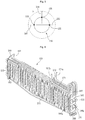
- FIG. 6 illustrates an example.
- FIG. 7 illustrate an example first pipe and an example second pipe.
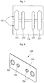
- FIG. 8 illustrates an example fin.
- the evaporator 150 includes a plurality of refrigerant pipes 151 and 170 through which the refrigerants having different states from each other flow, and a fin 155 which is coupled to the plurality of refrigerant pipes 151 and 170 and increases a heat exchange area between the refrigerant and a fluid.
- the plurality of refrigerant pipes 151 and 170 include the first pipe 151 through which the refrigerant depressurized in the first expander 105 flows during the first operation mode of the refrigerator 10, and the second pipe 170 through which the refrigerant flowing the first connection path 182 is supplied during the second operation mode of the refrigerator 10.
- the second pipe 170 forms at least a part of the hot gas paths 182 and 184, and may be referred to as a "hot gas pipe".
- the refrigerant of the second pipe 170 is the high temperature refrigerant compressed in the compressor 101, and may be depressurized in the first expander 105, and may have a higher temperature than that of the refrigerant flowing through the first pipe 151.
- the evaporator 150 further includes coupling plates 160 and 165 which fix the first pipe 151 and the second pipe 170.
- a plurality of coupling plates 160 and 165 may be provided at both sides of the evaporator 150.
- the coupling plates 160 and 165 include a first plate 160 which supports one side of each of the first pipe 151 and the second pipe 170, and a second plate 165 which supports the other side of each of the first pipe 151 and the second pipe 170.
- the first and second plates 160 and 165 may be disposed to be spaced apart from each other.
- the first pipe 151 and the second pipe 170 may be formed to be bent in one direction from the first plate 160 toward the second plate 165 and the other direction from the second plate 165 toward the first plate 160.
- first and second plates 160 and 165 serve to fix both sides of the first pipe 151 and the second pipe 170, and to prevent shaking of the first pipe 151 and the second pipe 170.
- first pipe 151 and the second pipe 170 may be disposed to pass through the first and second plates 160 and 165.
- Each of the first and second plates 160 and 165 has a plate shape which extends longitudinally, and may have through-holes 166a and 166b through which at least parts of the first pipe 151 and 170 pass.
- the through-holes 166a and 166b include a first through-hole 166a through which the first pipe 151 passes, and the second through-hole 166b through which the second pipe 170 passes.
- the first pipe 151 may be disposed to pass through the first through-hole 166a of the first plate 160, to extend toward the second plate 165, and to pass through the first through-hole 166a of the second plate 165, and then a direction thereof may be changed so as to extend again toward the first plate 160.
- the second pipe 170 may be disposed to pass through the second through-hole 166b of the first plate 160, to extend toward the second plate 165, and to pass through the second through-hole 166b of the second plate 165, and then a direction thereof may be changed so as to extend again toward the first plate 160.
- the evaporator 150 includes a first inlet part 151a which guides the introduction of the refrigerant into the first pipe 151, and a first outlet part 151b which guides the discharge of the refrigerant flowed through the first pipe 151.
- the first inlet part 151a and the first outlet part 151b form at least a part of the first pipe 151.
- the first inlet part 151a may be connected to the evaporator inlet pipe 197, and the first outlet part 151b may be connected to an evaporator outlet pipe 198 which is installed at an outlet side of the evaporator 150.
- the two-phase refrigerant depressurized in the first expander 105 is introduced into the evaporator 150 through the first inlet part 151a, evaporated therein, discharged from the evaporator 150 through the first outlet part 151b, and flows through the evaporator outlet pipe 198.
- the evaporator 150 includes a second inlet part 171 which guides the introduction of the refrigerant into the second pipe 170, and a second outlet part 172 which guides the discharge of the refrigerant flowed through the second pipe 170.
- the second inlet part 171 and the second outlet part 172 form at least a part of the second pipe 170.
- the second inlet part 171 may be connected to the first connection path 182, and the second outlet part 172 may be connected to the second connection path 184.
- the high temperature refrigerant flowing through the first connection path 182 is introduced into the evaporator 150 through the second inlet part 171, removes frost formed on the evaporator 150 while heat is exchanged, is discharged from the evaporator 150 through the second outlet part 172, and flows through the second connection path 184.
- a plurality of fins 155 are provided to be spaced apart from each other. And the first pipe 151 and the second pipe 170 are disposed to pass through the plurality of fins 155. In some implementations, the fins 155 may be disposed to vertically and horizontally form a plurality of rows.
- the coupling plates 160 and 165 include the hooks 162 and 167 which are coupled to the inner case 13.
- the hooks 162 and 167 are disposed at upper portions of the coupling plates 160 and 165, respectively.
- the hooks 162 and 167 include a first hook 162 which is provided at the first plate 160, and a second hook 167 which is provided at the second plate 165.
- First and second support parts 163 and 168 through which the second pipe 170 passes are formed at the coupling plates 160 and 165, respectively.
- the first and second support parts 163 and 168 are disposed at lower portions of the coupling plates 160 and 165, respectively.
- the first and second support parts 163 and 168 include a first support part 163 which is provided at the first plate 160, and a second support part 168 which is provided at the second plate 165.
- the second pipe 170 includes an extension part 175 which forms a lower end of the evaporator 150.
- the extension part 175 is formed to extend downward further than a lowermost fin 155 of the plurality of fins 155.
- the extension part 175 is located inside a water collection part 180 (referring to FIG. 11 ) which will be described later, and may supply heat to remaining frost in the water collection part 180. Defrosted water may be drained to a machinery compartment 50.
- the second pipe 170 may have a shape which is inserted into the first and second support parts 163 and 168 and extends to a central portion of the evaporator 150. That is, due to a configuration in which the second pipe 170 passes and extends through the first and second support parts 163 and 168, the extension part 175 may be stably supported by the evaporator 150.
- the first pipe 151 and the second pipe 170 may be installed to pass through the plurality of fins 155.
- the plurality of the fins 155 may be disposed to be spaced apart from each other at a predetermined distance.
- each of the fins 155 includes a fin body 156 having an approximately quadrangular plate shape, and a plurality of through-holes 157 and 158 which are formed at the fin body 156 and through which the first pipe 151 and the second pipe 170 pass.
- the plurality of through-holes 157 and 158 includes a first through-hole 157 through which the first pipe 151 passes, and a second through-hole 158 through which the second pipe 170 passes.
- the plurality of through-holes 157 and 158 may be disposed in one row.
- An inner diameter of the first through-hole 157 may have a size different from that of an inner diameter of the second through-hole 158.
- the inner diameter of the first through-hole 157 may be formed larger than that of the second through-hole 158.
- an outer diameter of the first pipe 151 may be formed larger than that of the second pipe 170.
- the first pipe 151 guides the flow of the refrigerant which performs an innate function of the evaporator 150, and thus a relatively large flow rate of the refrigerant is required.
- the second pipe 170 guides the flow of the high temperature refrigerant for a predetermined time only when the defrosting operation of the evaporator 150 is required, a relatively small flow rate of the refrigerant is required.
- the fin 155 further includes a collar 159 which protrudes from each of the first and second through-holes 157 and 158.
- the collar 159 may be understood as a structure which increases a contact area of each of the first and second pipes 151 and 170 inserted into the first and second through-holes 157 and 158, and reduces thermal resistance.
- the first and second pipes 151 and 170 may be inserted into the first and second through-holes 157 and 158, respectively, and then may be in close contact with the collar 159 through a pipe expanding process.
- a plurality of first through-holes 157 and a plurality of second through-holes 158 are formed.
- two second through-holes 158 may be disposed to be arranged between two first through-holes 157.
- the plurality of second through-holes 158 may be disposed between one first through-hole 157 and other first through-hole 157.
- a plurality of second pipes 170 may be located between a plurality of first pipes 151.
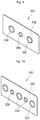
- FIGS. 9 and 10 illustrate example fins.
- a fin 255 includes a fin body 256, and a plurality of through-holes 257 and 258 which are formed at the fin body 256 and through which the first pipe 151 and the second pipe 170 pass.
- the plurality of through-holes 257 and 258 include a first through-hole 257 through which the first pipe 151 passes, and a second through-hole 258 through which the second pipe 170 passes.
- the plurality of through-holes 257 and 258 may be disposed in one row.
- An inner diameter of the first through-hole 257 may be formed larger than that of the second through-hole 258.
- the fin 255 further includes a collar 259 which protrudes from each of the first and second through-holes 257 and 258.
- the second through-hole 258 may be disposed between a plurality of first through-holes 257.
- one second through-hole 258 may be disposed to be arranged between two first through-holes 257.
- the second pipe 170 may be located between a plurality of first pipes 151.
- a fin 355 includes a fin body 356, and a plurality of through-holes 357 and 358 which are formed at the fin body 356 and through which the first pipe 151 and the second pipe 170 pass.
- the plurality of through-holes 357 and 358 include a first through-hole 357 through which the first pipe 151 passes, and a second through-hole 358 through which the second pipe 170 passes.
- the plurality of through-holes 357 and 358 may be disposed in one row.
- An inner diameter of the first through-hole 357 may be formed larger than that of the second through-hole 358.
- the fin 355 further includes a collar 359 which protrudes from each of the first and second through-holes 357 and 358.
- a plurality of first through-holes 357 and a plurality of second through-holes 358 are formed.
- the plurality of first through-holes 357 and the plurality of second through-holes 358 may be alternately disposed.
- three first through-holes 357 may be disposed to be spaced apart from each other, and two second through-holes 358 may be disposed to be spaced apart from each other.
- one second through-hole 358 may be disposed between two first through-holes 357.
- the first pipes 151 may be transversely disposed in three rows, and the second pipes 170 may be disposed in two rows, and each row of the first and second pipes 151 and 170 may be alternately disposed.
- FIGS. 11 and 12 illustrate example freezer compartment evaporators.
- the refrigerator 10 further includes the water collection part 180 which is installed at a lower side of the evaporator 150 to collect ice or water removed from the evaporator 150.
- the water collection part 180 extends in left and right directions to have a width corresponding to a transverse width of the evaporator 150.
- the water collection part 180 includes an inclined surface 183 which extends to be inclined downward toward an approximately central portion of the water collection part 180. Due to the inclined surface 182, the ice or the water removed from the evaporator 150 may flow toward the approximately central portion of the water collection part 180.
- a discharge part 185 through which the water stored in the water collection part 180 is discharged downward is formed at the approximately central portion of the water collection part 180. That is, the inclined surface 182 may extend to be inclined from both sides of the water collection part 180 toward the discharge part 185.
- the water discharged through the discharge part 185 may be introduced into the machinery compartment 50.
- a drainage pipe may be connected to the discharge part 185.
- the drainage pipe may extend downward from the discharge part 185, and may guide the water to a defrosted water pan installed at the machinery compartment 50.
- the extension part 175 of the second pipe 170 may be located inside the water collection part 180.
- the extension part 175 of the second pipe 170 includes a portion which extends to be inclined downward corresponding to an inclined shape of the water collection part 180.
- the extension part 175 may extend to be close to an upper surface of the water collection part 180 or to be spaced apart therefrom in a preset distance.
- the refrigerant flowing through the extension part 175 serves to melt the ice removed from the evaporator 150 and falling into the water collection part 180.
- a phase of the ice may be changed by heat supplied from the extension part 175 of the second pipe 170.
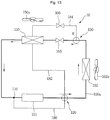
- FIGS. 13 and 14 illustrate example flows of a refrigerant during example operation modes.
- the first valve unit 120 and the second valve unit 130 may be controlled in a predetermined operation mode.
- the first operation mode may be referring to as a "general mode".
- the first valve unit 120 may be controlled in the first operation mode.
- the refrigerant compressed in the compressor 101 is introduced into the first port 121 of the first valve unit 120, and discharged through the second port 123.
- the refrigerant discharged from the first valve unit 120 may be introduced into the condenser 102, and then may be condensed.
- the refrigerant passed through the condenser 102 is introduced into the second valve unit 130.
- the second valve unit 130 may be controlled in the first operation mode.
- the refrigerant passed through the condenser 102 is introduced into the first port 131 of the second valve unit 130, and discharged through the second port 133.
- the refrigerant discharged from the second valve unit 130 is introduced into the first pipe 151 of the evaporator 150 via the evaporator inlet pipe 197. At this point, the refrigerant may be depressurized while passing through the first expander 105, and then may be introduced into the evaporator 150.
- the refrigerant is evaporated while flowing through the first pipe 151, then discharged from the evaporator 150, and flows through the evaporator outlet pipe 198. And the refrigerant may be suctioned into the compressor 101 and then may be compressed. This cycle may be repeated. That is, when the refrigerator 10 performs the first operation mode, the first valve unit 120 and the second valve unit 130 may be operated to restrict the flow of the refrigerant in the first and second connection paths 182 and 184.
- the first valve unit 120 and the second valve unit 130 may be controlled in a predetermined operation mode.
- the first valve unit 120 may be controlled in the second operation mode.
- the refrigerant compressed in the compressor 101 is introduced into the first port 121 of the first valve unit 120, and discharged through the third port 125.
- the refrigerant discharged from the first valve unit 120 flows through the first connection path 182.
- the refrigerant in the first connection path 182 is introduced into the evaporator 150 through the second pipe 170 of the evaporator 150. That is, the high temperature refrigerator compressed in the compressor 101 may be introduced into the evaporator 150. In this process, the refrigerant may supply heat to the evaporator 150, and thus may remove the ice formed on the evaporator 150. And the refrigerant flowing through the second pipe 170 of the evaporator 150 is discharged into the second connection path 184, and is depressurized in the second expander 106.
- the second valve unit 130 may be controlled in the second operation mode.
- the refrigerant in the second connection path 184 is introduced into the third port 135 of the second valve unit 130, and discharged through the first port 131.
- the refrigerant discharged from the second valve unit 130 is introduced into the condenser 102, and may be evaporated while passing through the condenser 102.
- the condenser fan 102a may be operated in a preset RPM.
- the refrigerant discharged from the condenser 102 may be introduced into the second port 123 of the first valve unit 120, and may be discharged through the fourth port 127 thereof.
- the refrigerant discharged from the first valve unit 120 may flow through the third connection path 186, and may be suctioned into the compressor 101 via the combination part 110. This cycle may be repeated.
- the high temperature refrigerant compressed in the compressor 101 may defrost the evaporator 150 while passing through the evaporator 150.
- the refrigerant may be condensed, is depressurized while passing through the second expander 106, and may be evaporated while passing through the condenser 102. Consequently, during the second operation mode of the refrigerator 10, functions of the condenser 102 and the evaporator 150 are changed contrary to a case of the first operation mode, e.g., the condenser 102 and the evaporator 150 may serve as the evaporator and the condenser, respectively. In this process, the evaporator 150 may be effectively defrosted.
- FIGS. 15 to 19 are graphs of example results of an experiment performed under example conditions in a refrigerator.
- a flow rate of the refrigerant, a defrosting time, and a temperature of the condenser 102 may be changed according to a design dimension, for example, a length or a diameter of the second expander 106 operated to depressurize the refrigerant when the refrigerator 10 performs the second operation mode
- the design dimension of the second expander 106 may be determined in advance so that the operation efficiency of the compressor 101 is improved while reducing the defrosting time.
- FIG. 15 is an experimental graph illustrating a state in which the flow rate kg/s of the refrigerant is changed according to a length mm of the second expander 106.
- a diameter of the second expander 106 has a constant value of A mm.
- the value of A may be 0.75 mm.
- input work or input power (hereinafter, referred to as input work) of the compressor 101 is fixed at a set value.
- the flow rate of the refrigerant is reduced. That is, when the length of the second expander 106 is increased, the resistance is increased in an aspect of the flow of the refrigerant, and thus the flow of the refrigerant is reduced.
- the flow of the refrigerant should have a set flow rate value m1 or more.
- the length of the second expander 106 which obtains the set flow rate value m1 is determined to be L1.
- the set flow rate value m1 is 0.00033 kg/s
- L1 is 2,000 mm
- the length of the second expander 106 may be determined to be 2,000 mm or less.
- FIG. 16 is an experimental graph illustrating the state in which the flow rate kg/s of the refrigerant is changed according to a diameter mm of the second expander 106.
- a length of the second expander 106 has a constant value of B mm.
- the value of B may be 2,000 mm.
- the input work of the compressor 101 is fixed at a set value.
- the flow rate of the refrigerant is increased. That is, when the diameter of the second expander 106 is increased, the resistance is reduced in the aspect of the flow of the refrigerant, and thus the flow of the refrigerant is increased.
- the flow of the refrigerant should have the set flow rate value m1 or more.
- the diameter of the second expander 106 which obtains the set flow rate value m1 or more is determined to be D1.
- D1 is 0.70 mm, and thus the diameter of the second expander 106 may be determined to be 0.70 mm or more.
- FIG. 17 is an experimental graph illustrating a change of the flow rate kg/s of the refrigerant which circulates in the refrigeration cycle of the refrigerator 10 according to an increase in a pressure drop bar with respect to a predetermined input work of the compressor 101.
- An experiment is performed four times while the input work of the compressor 101 is changed.
- the input work is increased from a first input work to a fourth input work of the compressor 101.
- a second input work may be determined larger by 20% than the first input work
- a third input work may be determined larger by 40% than the first input work
- the fourth input work may be determined larger by 60% than the first input work. This definition may be equally applied to FIG. 13 .
- the pressure drop of a horizontal axis indicates a pressure which is reduced in the second expander 106 after the evaporator 150 is defrosted. Based on a predetermined pressure drop, it may be understood that the flow rate of the refrigerant is increased as the input work of the compressor 101 is increased.
- the flow rate of the refrigerant is increased. That is, as an opening degree of the second expander 106 is increased, the pressure drop is reduced, but the flow rate of the refrigerant is increased.
- the second expander 106 is formed of a capillary tube, as a diameter of the capillary tube becomes larger or a length of the capillary tube becomes shorter, the pressure drop may be reduced, and the flow rate of the refrigerant may be increased.
- the defrosting time becomes shorter. That is, as the pressure drop becomes smaller, the flow rate of the refrigerant flowing through the hot gas paths 182 and 184 is increased. Accordingly, the defrosting performance is improved, and thus the defrosting time becomes shorter. And as the work input to the compressor 101 is increased, the flow rate of the refrigerant circulating the system is increased, and the defrosting time may be shorter.
- an evaporation temperature of the condenser 102 during the defrosting operation which is indicated at a vertical axis is reduced, as the pressure drop of the horizontal axis is increased.
- the evaporation temperature of the condenser 102 serves as a factor which determines a suction temperature of the refrigerant suctioned into the compressor 101, and thus it is important.
- the refrigerator 10 may be designed so that the pressure drop is maintained at a set value Po or more. That is, the length or an inner diameter of the second expander 106 may be determined so that the pressure drop is maintained at the set value Po or more.
- the set value To of the evaporation temperature may be about -5°C
- the set value Po of the pressure drop may be about 2.5 bar.
- the flow rate of the refrigerant may be increased, and the defrosting time may be shorter.
- the pressure drop is too small, the evaporation temperature or an evaporation pressure of the refrigerant is increased, and thus a load of the compressor 101 may be increased. Therefore, to maintain the pressure drop at the preset value or more when considering the operation efficiency of the compressor 101, the inner diameter of the second expander 106 should be determined to be the preset value or less and the length thereof should be determined to be the preset value or more.
- the inner diameter of the second expander 106 is determined to be 0.70 mm or more and 0.90 mm or less, and the length thereof is determined to be 1,700 mm or more and 2,000 mm or less.
- the preset input power of the compressor 101 may be 60 W.
- the defrosting of the evaporator can be performed using the high temperature refrigerant (or the hot gas), it is not necessary to install the conventional defrosting heater, and thus it is possible to reduce the cost.
- a reverse cycle is driven, and the high temperature refrigerant discharged from the compressor can flow to the evaporator which will be defrosted, can perform the defrosting operation, can be condensed during the defrosting operation, then can be depressurized, and can be evaporated while passing through the condenser.
- valve unit is provided at the inlet side and the outlet side of the condenser, and the flowing of the refrigerant can be controlled during the general operation or the defrosting operation, and thus the cooling operation of the storage compartment and the defrosting operation of the evaporator can be effectively performed.
- the evaporator includes the first pipe through which the refrigerant to be evaporated flows, the second pipe through which the high temperature refrigerant flows, and the fin to which the first and second pipes are coupled, and the ice formed on the evaporator can be melted during the defrosting operation using the high temperature refrigerant, and thus the defrosting efficiency can be improved.
- the defrosting of the evaporator is performed in a convection current method or a radiant method using the defrosting heater.
- the heat of the high temperature refrigerant can be transferred to the evaporator in a heat conduction method, and the defrosting efficiency is improved, and thus the defrosting time becomes shorter, and a temperature of the storage compartment can be prevented from being excessively increased during the defrosting operation.
- the fin and the first and second pipes are coupled through the collar provided at the fin, and the first and second pipes are in close contact with the collar of the fin through the pipe expanding process, contact thermal resistance can be reduced, and thus the defrosting time can be shortened.
- the extension part formed by extending at least a part of the second pipe is provided at the lower portion of the evaporator, and the high temperature refrigerant flows therethrough, the remaining ice in the water collection part can be effectively melted, and the defrosted water can be drained to the defrosted water pan.
- the defrosting of the evaporator using the high temperature refrigerant can be effectively performed.
- the cooling of the refrigerator compartment can be performed by driving the refrigerator compartment evaporator
- the cooling of the freezer compartment can be performed by driving the freezer compartment evaporator.
- the cooling performance can be prevented from being excessively degraded by the defrosting operation.
Landscapes
- Engineering & Computer Science (AREA)
- Physics & Mathematics (AREA)
- Mechanical Engineering (AREA)
- Thermal Sciences (AREA)
- General Engineering & Computer Science (AREA)
- Chemical & Material Sciences (AREA)
- Combustion & Propulsion (AREA)
- Geometry (AREA)
- Defrosting Systems (AREA)
Claims (12)
- Réfrigérateur (10) comprenant :un compresseur (101) qui est configuré pour comprimer un réfrigérant ;un condenseur (102) qui est configuré pour condenser un réfrigérant comprimé ;un premier tube capillaire (105) qui est configuré pour dépressuriser un réfrigérant condensé ;un évaporateur (150) qui est configuré pour évaporer un réfrigérant dépressurisé ;une première unité de soupape (120) qui est située au niveau d'un côté de sortie du compresseur (101) et qui est configurée pour guider un réfrigérant comprimé du compresseur (101) au condenseur (102) ;une seconde unité de soupape (130) qui est située au niveau d'un côté de sortie du condenseur (102) et qui est configurée pour guider un réfrigérant condensé du condenseur (102) à l'évaporateur (150) ; etun trajet de gaz chaud qui est raccordé à la première unité de soupape (120) et qui est configuré pour fournir un réfrigérant comprimé du compresseur (101) à l'évaporateur (150), un tuyau d'entrée d'évaporateur (197) s'étendant de la seconde unité de soupape (130) à l'évaporateur (150) ; et un tuyau de sortie d'évaporateur (198) qui est installé au niveau d'un côté de sortie de l'évaporateur (150) et configuré pour guider un réfrigérant de l'évaporateur (150) au compresseur (101),caractérisé en ce que :le trajet de gaz chaud comprend : un premier trajet de raccordement (182) qui s'étend de la première unité de soupape (120) à l'évaporateur (150) ; et un second trajet de raccordement (184) qui est raccordé au premier trajet de raccordement (182) ets'étend de l'évaporateur (150) à la seconde unité de soupape (130),le tube capillaire (105) est installé au niveau du tuyau d'entrée d'évaporateur (197) et un second tube capillaire (106) est installé au niveau du second trajet de raccordement (184).
- Réfrigérateur selon la revendication 1, dans lequel la première unité de soupape (120) comprend une soupape à quatre voies qui inclut quatre orifices, et qui comprend :un premier orifice (121) qui est raccordé à un tuyau de sortie du compresseur (101) ;un deuxième orifice (123) qui est raccordé à un tuyau d'entrée du condenseur (102) ; etun troisième orifice (125) qui est raccordé au premier trajet de raccordement (182).
- Réfrigérateur selon la revendication 2, comprenant en outre un troisième trajet de raccordement (186) qui s'étend de la première unité de soupape (120) à un tuyau côté aspiration du compresseur (101),
dans lequel la première unité de soupape (120) comprend en outre un quatrième orifice (127) qui est raccordé au troisième trajet de raccordement (186). - Réfrigérateur selon la revendication 1, dans lequel l'évaporateur (150) comprend :un premier tuyau (151) qui est raccordé au tuyau d'entrée d'évaporateur (197) ;un second tuyau (170) qui est raccordé au premier trajet de raccordement (182) et qui est raccordé au deuxième trajet de raccordement (184) ; etune ailette (155 ; 255 ; 355) qui est accouplée au premier tuyau (151) et au second tuyau (170).
- Réfrigérateur selon la revendication 1, dans lequel la seconde unité de soupape (130) comprend une soupape à trois voies qui inclut trois orifices, et qui comprend :un premier orifice (131) qui est raccordé à un tuyau qui raccorde le condenseur (102) à la seconde unité de soupape (130) ;un deuxième orifice (133) qui est raccordé au tuyau d'entrée d'évaporateur (197) ; etun troisième orifice (135) qui est raccordé au deuxième trajet de raccordement (184).
- Réfrigérateur selon l'une quelconque des revendications précédentes, dans lequel, sur la base de la réalisation d'un premier mode de fonctionnement :la première unité de soupape (120) est configurée pour guider un réfrigérant du compresseur (101) au condenseur (102), etla seconde unité de soupape (130) est configurée pour guider un réfrigérant du condenseur (102) au premier détendeur (105).
- Réfrigérateur selon la revendication 6, dans lequel, sur la base de la réalisation d'un second mode de fonctionnement :la première unité de soupape (120) est configurée pour guider un réfrigérant du compresseur (101) au trajet de gaz chaud et est configurée pour guider un réfrigérant du condenseur (102) à un tuyau côté aspiration du compresseur (101), etla seconde unité de soupape (130) est configurée pour guider un réfrigérant du trajet de gaz chaud au condenseur (102).
- Réfrigérateur selon l'une quelconque des revendications 4 à 7, dans lequel l'ailette (155 ; 255 ; 355) comprend :un premier trou traversant (157 ; 257 ; 357) qui est configuré pour recevoir le premier tuyau (151) ; etun second trou traversant (158 ; 258 ; 358) qui est configuré pour recevoir le second tuyau (170) et qui présente un diamètre intérieur qui est inférieur à un diamètre intérieur du premier trou traversant (157 ; 257 ; 357),dans lequel le premier trou traversant (157 ; 257 ; 357) et le second trou traversant (158 ; 258 ; 358) sont alignés le long d'un axe qui est perpendiculaire à un avant du réfrigérateur.
- Réfrigérateur selon la revendication 8, dans lequel l'ailette (155 ; 255 ; 355) comprend en outre :une pluralité de trous traversants supplémentaires (157 ; 257 ; 357) qui sont similaires au premier trou traversant (157 ; 257 ; 357),dans lequel le second trou traversant (158 ; 258 ; 358) est situé parmi la pluralité de trous traversants supplémentaires et le premier trou traversant (157 ; 257 ; 357).
- Réfrigérateur selon l'une quelconque des revendications précédentes, comprenant en outre :une partie de collecte d'eau (180) qui est située au niveau d'un côté inférieur de l'évaporateur (150) et qui est configurée pour recevoir de la glace ou de l'eau condensée sur l'évaporateur (150) ; etune partie d'extension (175) qui est située au niveau du second tuyau, qui est située à l'intérieur de la partie de collecte d'eau (180), et qui est configurée pour faire fondre la glace dans la partie de collecte d'eau (180) en fournissant de la chaleur.
- Réfrigérateur selon la revendication 10, dans lequel la partie d'extension (175) est située sous l'ailette (155 ; 255 ; 355).
- Réfrigérateur selon la revendication 10, ou 11, dans lequel la partie de collecte d'eau (180) comprend une partie de décharge (185) qui est configurée pour recevoir de l'eau décongelée de la partie de collecte d'eau (180), et qui inclut une surface inclinée (182) qui est inclinée vers le bas à partir des deux côtés de la partie de collecte d'eau (180) vers la partie de décharge (185),
dans lequel la partie d'extension (175) inclut une surface inclinée qui est inclinée selon un angle similaire à la surface inclinée de la partie de collecte d'eau (180).
Applications Claiming Priority (2)
| Application Number | Priority Date | Filing Date | Title |
|---|---|---|---|
| KR1020150088507A KR102329452B1 (ko) | 2015-06-22 | 2015-06-22 | 냉장고 |
| KR1020150106879A KR102407651B1 (ko) | 2015-07-28 | 2015-07-28 | 냉장고 |
Publications (2)
| Publication Number | Publication Date |
|---|---|
| EP3109572A1 EP3109572A1 (fr) | 2016-12-28 |
| EP3109572B1 true EP3109572B1 (fr) | 2019-05-01 |
Family
ID=56116261
Family Applications (1)
| Application Number | Title | Priority Date | Filing Date |
|---|---|---|---|
| EP16172645.0A Active EP3109572B1 (fr) | 2015-06-22 | 2016-06-02 | Réfrigérateur |
Country Status (2)
| Country | Link |
|---|---|
| US (1) | US10746445B2 (fr) |
| EP (1) | EP3109572B1 (fr) |
Families Citing this family (4)
| Publication number | Priority date | Publication date | Assignee | Title |
|---|---|---|---|---|
| EP3109572B1 (fr) * | 2015-06-22 | 2019-05-01 | Lg Electronics Inc. | Réfrigérateur |
| US11221151B2 (en) * | 2019-01-15 | 2022-01-11 | Johnson Controls Technology Company | Hot gas reheat systems and methods |
| KR20210001150A (ko) * | 2019-06-27 | 2021-01-06 | 삼성전자주식회사 | 열교환기 및 이를 포함하는 냉장고 |
| CN111964338A (zh) * | 2020-08-03 | 2020-11-20 | 星崎电机(苏州)有限公司 | 一种冰箱库内电加热联动控制系统 |
Family Cites Families (47)
| Publication number | Priority date | Publication date | Assignee | Title |
|---|---|---|---|---|
| DE288207C (fr) | ||||
| US2969959A (en) * | 1957-01-11 | 1961-01-31 | Gen Motors Corp | Refrigerating apparatus |
| US2875595A (en) * | 1957-08-19 | 1959-03-03 | Dole Refrigerating Co | Eutectic blower unit for refrigerating spaces |
| US3015939A (en) * | 1959-06-22 | 1962-01-09 | Maurice W Brainard | Heating and freezing system |
| US3167930A (en) * | 1962-11-19 | 1965-02-02 | Freightliner Corp | Refrigeration system |
| US3209814A (en) * | 1963-04-03 | 1965-10-05 | Transicold Corp | Refrigeration system |
| US3213637A (en) * | 1963-10-28 | 1965-10-26 | Recold Corp | Refrigeration defrost system |
| US3386259A (en) * | 1966-06-20 | 1968-06-04 | Cummins Engine Co Inc | Air conditioning apparatus with hot gas heating means |
| US3677025A (en) * | 1971-01-13 | 1972-07-18 | Borg Warner | Defrosting arrangement and method for a refrigeration system |
| US3978684A (en) * | 1975-04-17 | 1976-09-07 | Thermo King Corporation | Refrigeration system |
| US4043144A (en) * | 1976-06-17 | 1977-08-23 | Dole Refrigerating Company | Hot gas defrost system |
| US4215555A (en) * | 1978-10-02 | 1980-08-05 | Carrier Corporation | Hot gas defrost system |
| JPS589911B2 (ja) * | 1978-11-29 | 1983-02-23 | 株式会社日立製作所 | 冷凍機用蒸発器 |
| FR2571127B3 (fr) * | 1984-09-28 | 1986-11-21 | Leroy Somer Moteurs | Machine frigorifique reversible a quantite variable de fluide refrigerant utile |
| US4722388A (en) * | 1986-09-08 | 1988-02-02 | Drury Chauncey R | Heat exchanger |
| DD288207A5 (de) * | 1989-09-29 | 1991-03-21 | Veb Maschinenfabrik Halle,De | Einrichtung zum gasdichten absperren der druckleitung einer kompressionskaelteanlage |
| US5050400A (en) * | 1990-02-26 | 1991-09-24 | Bohn, Inc. | Simplified hot gas defrost refrigeration system |
| US5315836A (en) * | 1993-01-15 | 1994-05-31 | Mccormack Manufacturing Co., Inc. | Air cooling unit having a hot gas defrost circuit |
| US5784896A (en) * | 1996-10-18 | 1998-07-28 | White Consolidated Industries, Inc. | Freezer or refrigerator construction suitable for food service use |
| US5896753A (en) * | 1996-10-18 | 1999-04-27 | Lg Electronics Inc. | Freezing cycle apparatus having quick freezing and thawing functions |
| US5809789A (en) * | 1997-05-07 | 1998-09-22 | Baker; Philip L. | Refrigeration module |
| US6705107B2 (en) * | 1998-10-06 | 2004-03-16 | Manitowoc Foodservice Companies, Inc. | Compact ice making machine with cool vapor defrost |
| US6318107B1 (en) * | 1999-06-15 | 2001-11-20 | D. S. Inc. (Defrost Systems Inc.) | Advanced defrost system |
| JP2001173977A (ja) * | 1999-12-10 | 2001-06-29 | Samsung Electronics Co Ltd | 冷凍サイクル用熱交換器及びその製造方法 |
| KR100506610B1 (ko) * | 2003-12-12 | 2005-08-08 | 삼성전자주식회사 | 냉동장치 및 그 냉동장치를 갖는 냉장고 |
| TW200532153A (en) * | 2004-01-07 | 2005-10-01 | Shinmaywa Ind Ltd | Ultra-low temperature refrigerating equipment, refrigerating system, and vacuum plant |
| US8561420B2 (en) * | 2009-05-08 | 2013-10-22 | Honda Motor Co., Ltd. | Evaporator assembly for an HVAC system |
| AU2011258052B2 (en) * | 2010-05-27 | 2016-06-16 | XDX Global, LLC | Surged heat pump systems |
| US20120023993A1 (en) * | 2010-07-27 | 2012-02-02 | Palmer Roger C | Evaporator with integrated heating element |
| JP5619295B2 (ja) * | 2011-10-03 | 2014-11-05 | 三菱電機株式会社 | 冷凍サイクル装置 |
| WO2013171803A1 (fr) * | 2012-05-18 | 2013-11-21 | 三菱電機株式会社 | Dispositif de pompe à chaleur |
| KR20140070012A (ko) * | 2012-11-30 | 2014-06-10 | 엘지전자 주식회사 | 열 교환기 및 그 제조 방법 |
| US9046287B2 (en) * | 2013-03-15 | 2015-06-02 | Whirlpool Corporation | Specialty cooling features using extruded evaporator |
| EP2985559B1 (fr) * | 2013-04-09 | 2019-06-12 | Panasonic Intellectual Property Management Co., Ltd. | Ailette de transfert de chaleur, échangeur de chaleur et dispositif à cycle frigorifique |
| JP6204111B2 (ja) * | 2013-08-09 | 2017-09-27 | 株式会社日本クライメイトシステムズ | 車両用空調装置 |
| US10442272B2 (en) * | 2014-08-22 | 2019-10-15 | Thermo King Corporation | Method and system for defrosting a heat exchanger |
| US20160061536A1 (en) * | 2014-08-26 | 2016-03-03 | Cerro Flow Products Llc | Heat Exchanger and Method of Assembling the Same |
| JP6478544B2 (ja) * | 2014-09-29 | 2019-03-06 | サンデンホールディングス株式会社 | 自動販売機 |
| EP3209957B1 (fr) * | 2014-10-21 | 2021-04-07 | LG Electronics Inc. | Dispositif de dégivrage et réfrigérateur le comprenant |
| CN107076477B (zh) * | 2014-11-24 | 2021-04-27 | 开利公司 | 用于自由和积极除霜的系统和方法 |
| DE102014225102A1 (de) * | 2014-12-08 | 2016-06-09 | BSH Hausgeräte GmbH | No-Frost-Kältegerät |
| KR102336200B1 (ko) * | 2014-12-24 | 2021-12-08 | 삼성전자주식회사 | 냉장고 |
| US10935329B2 (en) * | 2015-01-19 | 2021-03-02 | Hussmann Corporation | Heat exchanger with heater insert |
| EP3109572B1 (fr) * | 2015-06-22 | 2019-05-01 | Lg Electronics Inc. | Réfrigérateur |
| KR102479532B1 (ko) * | 2015-07-28 | 2022-12-21 | 엘지전자 주식회사 | 냉장고 |
| KR102480701B1 (ko) * | 2015-07-28 | 2022-12-23 | 엘지전자 주식회사 | 냉장고 |
| KR102493237B1 (ko) * | 2015-11-11 | 2023-01-30 | 엘지전자 주식회사 | 제상 장치 및 이를 구비하는 냉장고 |
-
2016
- 2016-06-02 EP EP16172645.0A patent/EP3109572B1/fr active Active
- 2016-06-21 US US15/188,248 patent/US10746445B2/en active Active
Non-Patent Citations (1)
| Title |
|---|
| None * |
Also Published As
| Publication number | Publication date |
|---|---|
| US20160370046A1 (en) | 2016-12-22 |
| EP3109572A1 (fr) | 2016-12-28 |
| US10746445B2 (en) | 2020-08-18 |
Similar Documents
| Publication | Publication Date | Title |
|---|---|---|
| US11867447B2 (en) | Refrigerator | |
| US11578903B2 (en) | Refrigerator | |
| US11073317B2 (en) | Refrigerator | |
| KR101631904B1 (ko) | 냉장고 | |
| KR101649624B1 (ko) | 냉장고 | |
| EP3109572B1 (fr) | Réfrigérateur | |
| US10041716B2 (en) | Refrigerator | |
| JP6687384B2 (ja) | 冷蔵庫 | |
| KR102289303B1 (ko) | 냉장고 및 그 제어방법 | |
| KR102407651B1 (ko) | 냉장고 | |
| KR102329452B1 (ko) | 냉장고 | |
| JP6697040B2 (ja) | 冷蔵庫 | |
| KR20160141583A (ko) | 냉장고 |
Legal Events
| Date | Code | Title | Description |
|---|---|---|---|
| PUAI | Public reference made under article 153(3) epc to a published international application that has entered the european phase |
Free format text: ORIGINAL CODE: 0009012 |
|
| STAA | Information on the status of an ep patent application or granted ep patent |
Free format text: STATUS: REQUEST FOR EXAMINATION WAS MADE |
|
| 17P | Request for examination filed |
Effective date: 20160702 |
|
| AK | Designated contracting states |
Kind code of ref document: A1 Designated state(s): AL AT BE BG CH CY CZ DE DK EE ES FI FR GB GR HR HU IE IS IT LI LT LU LV MC MK MT NL NO PL PT RO RS SE SI SK SM TR |
|
| AX | Request for extension of the european patent |
Extension state: BA ME |
|
| RBV | Designated contracting states (corrected) |
Designated state(s): AL AT BE BG CH CY CZ DE DK EE ES FI FR GB GR HR HU IE IS IT LI LT LU LV MC MK MT NL NO PL PT RO RS SE SI SK SM TR |
|
| GRAP | Despatch of communication of intention to grant a patent |
Free format text: ORIGINAL CODE: EPIDOSNIGR1 |
|
| STAA | Information on the status of an ep patent application or granted ep patent |
Free format text: STATUS: GRANT OF PATENT IS INTENDED |
|
| RIC1 | Information provided on ipc code assigned before grant |
Ipc: F25B 47/02 20060101AFI20181109BHEP |
|
| INTG | Intention to grant announced |
Effective date: 20181130 |
|
| GRAS | Grant fee paid |
Free format text: ORIGINAL CODE: EPIDOSNIGR3 |
|
| GRAA | (expected) grant |
Free format text: ORIGINAL CODE: 0009210 |
|
| STAA | Information on the status of an ep patent application or granted ep patent |
Free format text: STATUS: THE PATENT HAS BEEN GRANTED |
|
| AK | Designated contracting states |
Kind code of ref document: B1 Designated state(s): AL AT BE BG CH CY CZ DE DK EE ES FI FR GB GR HR HU IE IS IT LI LT LU LV MC MK MT NL NO PL PT RO RS SE SI SK SM TR |
|
| REG | Reference to a national code |
Ref country code: GB Ref legal event code: FG4D |
|
| REG | Reference to a national code |
Ref country code: CH Ref legal event code: EP Ref country code: AT Ref legal event code: REF Ref document number: 1127479 Country of ref document: AT Kind code of ref document: T Effective date: 20190515 |
|
| REG | Reference to a national code |
Ref country code: DE Ref legal event code: R096 Ref document number: 602016013054 Country of ref document: DE |
|
| REG | Reference to a national code |
Ref country code: IE Ref legal event code: FG4D |
|
| REG | Reference to a national code |
Ref country code: NL Ref legal event code: MP Effective date: 20190501 |
|
| REG | Reference to a national code |
Ref country code: LT Ref legal event code: MG4D |
|
| PG25 | Lapsed in a contracting state [announced via postgrant information from national office to epo] |
Ref country code: FI Free format text: LAPSE BECAUSE OF FAILURE TO SUBMIT A TRANSLATION OF THE DESCRIPTION OR TO PAY THE FEE WITHIN THE PRESCRIBED TIME-LIMIT Effective date: 20190501 Ref country code: HR Free format text: LAPSE BECAUSE OF FAILURE TO SUBMIT A TRANSLATION OF THE DESCRIPTION OR TO PAY THE FEE WITHIN THE PRESCRIBED TIME-LIMIT Effective date: 20190501 Ref country code: AL Free format text: LAPSE BECAUSE OF FAILURE TO SUBMIT A TRANSLATION OF THE DESCRIPTION OR TO PAY THE FEE WITHIN THE PRESCRIBED TIME-LIMIT Effective date: 20190501 Ref country code: NO Free format text: LAPSE BECAUSE OF FAILURE TO SUBMIT A TRANSLATION OF THE DESCRIPTION OR TO PAY THE FEE WITHIN THE PRESCRIBED TIME-LIMIT Effective date: 20190801 Ref country code: SE Free format text: LAPSE BECAUSE OF FAILURE TO SUBMIT A TRANSLATION OF THE DESCRIPTION OR TO PAY THE FEE WITHIN THE PRESCRIBED TIME-LIMIT Effective date: 20190501 Ref country code: PT Free format text: LAPSE BECAUSE OF FAILURE TO SUBMIT A TRANSLATION OF THE DESCRIPTION OR TO PAY THE FEE WITHIN THE PRESCRIBED TIME-LIMIT Effective date: 20190901 Ref country code: ES Free format text: LAPSE BECAUSE OF FAILURE TO SUBMIT A TRANSLATION OF THE DESCRIPTION OR TO PAY THE FEE WITHIN THE PRESCRIBED TIME-LIMIT Effective date: 20190501 Ref country code: LT Free format text: LAPSE BECAUSE OF FAILURE TO SUBMIT A TRANSLATION OF THE DESCRIPTION OR TO PAY THE FEE WITHIN THE PRESCRIBED TIME-LIMIT Effective date: 20190501 Ref country code: NL Free format text: LAPSE BECAUSE OF FAILURE TO SUBMIT A TRANSLATION OF THE DESCRIPTION OR TO PAY THE FEE WITHIN THE PRESCRIBED TIME-LIMIT Effective date: 20190501 |
|
| PG25 | Lapsed in a contracting state [announced via postgrant information from national office to epo] |
Ref country code: BG Free format text: LAPSE BECAUSE OF FAILURE TO SUBMIT A TRANSLATION OF THE DESCRIPTION OR TO PAY THE FEE WITHIN THE PRESCRIBED TIME-LIMIT Effective date: 20190801 Ref country code: RS Free format text: LAPSE BECAUSE OF FAILURE TO SUBMIT A TRANSLATION OF THE DESCRIPTION OR TO PAY THE FEE WITHIN THE PRESCRIBED TIME-LIMIT Effective date: 20190501 Ref country code: LV Free format text: LAPSE BECAUSE OF FAILURE TO SUBMIT A TRANSLATION OF THE DESCRIPTION OR TO PAY THE FEE WITHIN THE PRESCRIBED TIME-LIMIT Effective date: 20190501 Ref country code: GR Free format text: LAPSE BECAUSE OF FAILURE TO SUBMIT A TRANSLATION OF THE DESCRIPTION OR TO PAY THE FEE WITHIN THE PRESCRIBED TIME-LIMIT Effective date: 20190802 |
|
| REG | Reference to a national code |
Ref country code: AT Ref legal event code: MK05 Ref document number: 1127479 Country of ref document: AT Kind code of ref document: T Effective date: 20190501 |
|
| PG25 | Lapsed in a contracting state [announced via postgrant information from national office to epo] |
Ref country code: IS Free format text: LAPSE BECAUSE OF FAILURE TO SUBMIT A TRANSLATION OF THE DESCRIPTION OR TO PAY THE FEE WITHIN THE PRESCRIBED TIME-LIMIT Effective date: 20190901 |
|
| PG25 | Lapsed in a contracting state [announced via postgrant information from national office to epo] |
Ref country code: RO Free format text: LAPSE BECAUSE OF FAILURE TO SUBMIT A TRANSLATION OF THE DESCRIPTION OR TO PAY THE FEE WITHIN THE PRESCRIBED TIME-LIMIT Effective date: 20190501 Ref country code: SK Free format text: LAPSE BECAUSE OF FAILURE TO SUBMIT A TRANSLATION OF THE DESCRIPTION OR TO PAY THE FEE WITHIN THE PRESCRIBED TIME-LIMIT Effective date: 20190501 Ref country code: EE Free format text: LAPSE BECAUSE OF FAILURE TO SUBMIT A TRANSLATION OF THE DESCRIPTION OR TO PAY THE FEE WITHIN THE PRESCRIBED TIME-LIMIT Effective date: 20190501 Ref country code: DK Free format text: LAPSE BECAUSE OF FAILURE TO SUBMIT A TRANSLATION OF THE DESCRIPTION OR TO PAY THE FEE WITHIN THE PRESCRIBED TIME-LIMIT Effective date: 20190501 Ref country code: AT Free format text: LAPSE BECAUSE OF FAILURE TO SUBMIT A TRANSLATION OF THE DESCRIPTION OR TO PAY THE FEE WITHIN THE PRESCRIBED TIME-LIMIT Effective date: 20190501 Ref country code: MC Free format text: LAPSE BECAUSE OF FAILURE TO SUBMIT A TRANSLATION OF THE DESCRIPTION OR TO PAY THE FEE WITHIN THE PRESCRIBED TIME-LIMIT Effective date: 20190501 Ref country code: CZ Free format text: LAPSE BECAUSE OF FAILURE TO SUBMIT A TRANSLATION OF THE DESCRIPTION OR TO PAY THE FEE WITHIN THE PRESCRIBED TIME-LIMIT Effective date: 20190501 |
|
| REG | Reference to a national code |
Ref country code: CH Ref legal event code: PL |
|
| REG | Reference to a national code |
Ref country code: DE Ref legal event code: R097 Ref document number: 602016013054 Country of ref document: DE |
|
| PG25 | Lapsed in a contracting state [announced via postgrant information from national office to epo] |
Ref country code: SM Free format text: LAPSE BECAUSE OF FAILURE TO SUBMIT A TRANSLATION OF THE DESCRIPTION OR TO PAY THE FEE WITHIN THE PRESCRIBED TIME-LIMIT Effective date: 20190501 |
|
| PLBE | No opposition filed within time limit |
Free format text: ORIGINAL CODE: 0009261 |
|
| STAA | Information on the status of an ep patent application or granted ep patent |
Free format text: STATUS: NO OPPOSITION FILED WITHIN TIME LIMIT |
|
| REG | Reference to a national code |
Ref country code: BE Ref legal event code: MM Effective date: 20190630 |
|
| PG25 | Lapsed in a contracting state [announced via postgrant information from national office to epo] |
Ref country code: TR Free format text: LAPSE BECAUSE OF FAILURE TO SUBMIT A TRANSLATION OF THE DESCRIPTION OR TO PAY THE FEE WITHIN THE PRESCRIBED TIME-LIMIT Effective date: 20190501 |
|
| 26N | No opposition filed |
Effective date: 20200204 |
|
| PG25 | Lapsed in a contracting state [announced via postgrant information from national office to epo] |
Ref country code: IE Free format text: LAPSE BECAUSE OF NON-PAYMENT OF DUE FEES Effective date: 20190602 Ref country code: PL Free format text: LAPSE BECAUSE OF FAILURE TO SUBMIT A TRANSLATION OF THE DESCRIPTION OR TO PAY THE FEE WITHIN THE PRESCRIBED TIME-LIMIT Effective date: 20190501 |
|
| PG25 | Lapsed in a contracting state [announced via postgrant information from national office to epo] |
Ref country code: CH Free format text: LAPSE BECAUSE OF NON-PAYMENT OF DUE FEES Effective date: 20190630 Ref country code: SI Free format text: LAPSE BECAUSE OF FAILURE TO SUBMIT A TRANSLATION OF THE DESCRIPTION OR TO PAY THE FEE WITHIN THE PRESCRIBED TIME-LIMIT Effective date: 20190501 Ref country code: BE Free format text: LAPSE BECAUSE OF NON-PAYMENT OF DUE FEES Effective date: 20190630 Ref country code: LU Free format text: LAPSE BECAUSE OF NON-PAYMENT OF DUE FEES Effective date: 20190602 Ref country code: LI Free format text: LAPSE BECAUSE OF NON-PAYMENT OF DUE FEES Effective date: 20190630 |
|
| PG25 | Lapsed in a contracting state [announced via postgrant information from national office to epo] |
Ref country code: CY Free format text: LAPSE BECAUSE OF FAILURE TO SUBMIT A TRANSLATION OF THE DESCRIPTION OR TO PAY THE FEE WITHIN THE PRESCRIBED TIME-LIMIT Effective date: 20190501 |
|
| PG25 | Lapsed in a contracting state [announced via postgrant information from national office to epo] |
Ref country code: MT Free format text: LAPSE BECAUSE OF FAILURE TO SUBMIT A TRANSLATION OF THE DESCRIPTION OR TO PAY THE FEE WITHIN THE PRESCRIBED TIME-LIMIT Effective date: 20190501 Ref country code: HU Free format text: LAPSE BECAUSE OF FAILURE TO SUBMIT A TRANSLATION OF THE DESCRIPTION OR TO PAY THE FEE WITHIN THE PRESCRIBED TIME-LIMIT; INVALID AB INITIO Effective date: 20160602 |
|
| PG25 | Lapsed in a contracting state [announced via postgrant information from national office to epo] |
Ref country code: MK Free format text: LAPSE BECAUSE OF FAILURE TO SUBMIT A TRANSLATION OF THE DESCRIPTION OR TO PAY THE FEE WITHIN THE PRESCRIBED TIME-LIMIT Effective date: 20190501 |
|
| P01 | Opt-out of the competence of the unified patent court (upc) registered |
Effective date: 20230524 |
|
| PGFP | Annual fee paid to national office [announced via postgrant information from national office to epo] |
Ref country code: IT Payment date: 20230509 Year of fee payment: 8 Ref country code: FR Payment date: 20230510 Year of fee payment: 8 Ref country code: DE Payment date: 20230508 Year of fee payment: 8 |
|
| PGFP | Annual fee paid to national office [announced via postgrant information from national office to epo] |
Ref country code: GB Payment date: 20230509 Year of fee payment: 8 |