EP3109499B1 - Scheibenbremse, insbesondere für nutzfahrzeuge - Google Patents
Scheibenbremse, insbesondere für nutzfahrzeuge Download PDFInfo
- Publication number
- EP3109499B1 EP3109499B1 EP15001864.6A EP15001864A EP3109499B1 EP 3109499 B1 EP3109499 B1 EP 3109499B1 EP 15001864 A EP15001864 A EP 15001864A EP 3109499 B1 EP3109499 B1 EP 3109499B1
- Authority
- EP
- European Patent Office
- Prior art keywords
- brake
- disc
- shaft
- pressure piece
- stop
- Prior art date
- Legal status (The legal status is an assumption and is not a legal conclusion. Google has not performed a legal analysis and makes no representation as to the accuracy of the status listed.)
- Active
Links
Images



Classifications
-
- F—MECHANICAL ENGINEERING; LIGHTING; HEATING; WEAPONS; BLASTING
- F16—ENGINEERING ELEMENTS AND UNITS; GENERAL MEASURES FOR PRODUCING AND MAINTAINING EFFECTIVE FUNCTIONING OF MACHINES OR INSTALLATIONS; THERMAL INSULATION IN GENERAL
- F16D—COUPLINGS FOR TRANSMITTING ROTATION; CLUTCHES; BRAKES
- F16D55/00—Brakes with substantially-radial braking surfaces pressed together in axial direction, e.g. disc brakes
- F16D55/02—Brakes with substantially-radial braking surfaces pressed together in axial direction, e.g. disc brakes with axially-movable discs or pads pressed against axially-located rotating members
- F16D55/22—Brakes with substantially-radial braking surfaces pressed together in axial direction, e.g. disc brakes with axially-movable discs or pads pressed against axially-located rotating members by clamping an axially-located rotating disc between movable braking members, e.g. movable brake discs or brake pads
-
- B—PERFORMING OPERATIONS; TRANSPORTING
- B60—VEHICLES IN GENERAL
- B60T—VEHICLE BRAKE CONTROL SYSTEMS OR PARTS THEREOF; BRAKE CONTROL SYSTEMS OR PARTS THEREOF, IN GENERAL; ARRANGEMENT OF BRAKING ELEMENTS ON VEHICLES IN GENERAL; PORTABLE DEVICES FOR PREVENTING UNWANTED MOVEMENT OF VEHICLES; VEHICLE MODIFICATIONS TO FACILITATE COOLING OF BRAKES
- B60T1/00—Arrangements of braking elements, i.e. of those parts where braking effect occurs specially for vehicles
- B60T1/02—Arrangements of braking elements, i.e. of those parts where braking effect occurs specially for vehicles acting by retarding wheels
- B60T1/06—Arrangements of braking elements, i.e. of those parts where braking effect occurs specially for vehicles acting by retarding wheels acting otherwise than on tread, e.g. employing rim, drum, disc, or transmission or on double wheels
-
- B—PERFORMING OPERATIONS; TRANSPORTING
- B60—VEHICLES IN GENERAL
- B60T—VEHICLE BRAKE CONTROL SYSTEMS OR PARTS THEREOF; BRAKE CONTROL SYSTEMS OR PARTS THEREOF, IN GENERAL; ARRANGEMENT OF BRAKING ELEMENTS ON VEHICLES IN GENERAL; PORTABLE DEVICES FOR PREVENTING UNWANTED MOVEMENT OF VEHICLES; VEHICLE MODIFICATIONS TO FACILITATE COOLING OF BRAKES
- B60T13/00—Transmitting braking action from initiating means to ultimate brake actuator with power assistance or drive; Brake systems incorporating such transmitting means, e.g. air-pressure brake systems
- B60T13/10—Transmitting braking action from initiating means to ultimate brake actuator with power assistance or drive; Brake systems incorporating such transmitting means, e.g. air-pressure brake systems with fluid assistance, drive, or release
- B60T13/12—Transmitting braking action from initiating means to ultimate brake actuator with power assistance or drive; Brake systems incorporating such transmitting means, e.g. air-pressure brake systems with fluid assistance, drive, or release the fluid being liquid
-
- F—MECHANICAL ENGINEERING; LIGHTING; HEATING; WEAPONS; BLASTING
- F16—ENGINEERING ELEMENTS AND UNITS; GENERAL MEASURES FOR PRODUCING AND MAINTAINING EFFECTIVE FUNCTIONING OF MACHINES OR INSTALLATIONS; THERMAL INSULATION IN GENERAL
- F16D—COUPLINGS FOR TRANSMITTING ROTATION; CLUTCHES; BRAKES
- F16D65/00—Parts or details
- F16D65/14—Actuating mechanisms for brakes; Means for initiating operation at a predetermined position
- F16D65/16—Actuating mechanisms for brakes; Means for initiating operation at a predetermined position arranged in or on the brake
- F16D65/18—Actuating mechanisms for brakes; Means for initiating operation at a predetermined position arranged in or on the brake adapted for drawing members together, e.g. for disc brakes
-
- F—MECHANICAL ENGINEERING; LIGHTING; HEATING; WEAPONS; BLASTING
- F16—ENGINEERING ELEMENTS AND UNITS; GENERAL MEASURES FOR PRODUCING AND MAINTAINING EFFECTIVE FUNCTIONING OF MACHINES OR INSTALLATIONS; THERMAL INSULATION IN GENERAL
- F16D—COUPLINGS FOR TRANSMITTING ROTATION; CLUTCHES; BRAKES
- F16D2121/00—Type of actuator operation force
- F16D2121/14—Mechanical
-
- F—MECHANICAL ENGINEERING; LIGHTING; HEATING; WEAPONS; BLASTING
- F16—ENGINEERING ELEMENTS AND UNITS; GENERAL MEASURES FOR PRODUCING AND MAINTAINING EFFECTIVE FUNCTIONING OF MACHINES OR INSTALLATIONS; THERMAL INSULATION IN GENERAL
- F16D—COUPLINGS FOR TRANSMITTING ROTATION; CLUTCHES; BRAKES
- F16D2125/00—Components of actuators
- F16D2125/18—Mechanical mechanisms
- F16D2125/20—Mechanical mechanisms converting rotation to linear movement or vice versa
- F16D2125/22—Mechanical mechanisms converting rotation to linear movement or vice versa acting transversely to the axis of rotation
- F16D2125/26—Cranks
-
- F—MECHANICAL ENGINEERING; LIGHTING; HEATING; WEAPONS; BLASTING
- F16—ENGINEERING ELEMENTS AND UNITS; GENERAL MEASURES FOR PRODUCING AND MAINTAINING EFFECTIVE FUNCTIONING OF MACHINES OR INSTALLATIONS; THERMAL INSULATION IN GENERAL
- F16D—COUPLINGS FOR TRANSMITTING ROTATION; CLUTCHES; BRAKES
- F16D2125/00—Components of actuators
- F16D2125/18—Mechanical mechanisms
- F16D2125/20—Mechanical mechanisms converting rotation to linear movement or vice versa
- F16D2125/22—Mechanical mechanisms converting rotation to linear movement or vice versa acting transversely to the axis of rotation
- F16D2125/28—Cams; Levers with cams
- F16D2125/32—Cams; Levers with cams acting on one cam follower
-
- F—MECHANICAL ENGINEERING; LIGHTING; HEATING; WEAPONS; BLASTING
- F16—ENGINEERING ELEMENTS AND UNITS; GENERAL MEASURES FOR PRODUCING AND MAINTAINING EFFECTIVE FUNCTIONING OF MACHINES OR INSTALLATIONS; THERMAL INSULATION IN GENERAL
- F16D—COUPLINGS FOR TRANSMITTING ROTATION; CLUTCHES; BRAKES
- F16D2125/00—Components of actuators
- F16D2125/18—Mechanical mechanisms
- F16D2125/58—Mechanical mechanisms transmitting linear movement
- F16D2125/64—Levers
Definitions
- the invention relates to a disc brake, in particular for commercial vehicles according to the preamble of claim 1 ( EP 1 160 447 ).
- Similar disc brakes are for example from the CN 102 242 786 A. and the DE 10 2010 005 909 A1 known. Thereafter, so-called guide strips are provided which limit the displaceability of both the pressure piece and the brake shaft with respect to the brake disc in a direction parallel to the axis of rotation of the brake shaft to a predetermined dimension.
- the predetermined dimension is zero or close to zero, because the guide strips - according to their designation - should guide the pressure piece or the brake shaft in the axial direction when braking or applying the brakes, but at the same time it must be ensured that the components mentioned are not jam.
- the part of the guide strips which is intended to restrict the displaceability of the brake shaft lies deep inside the brake caliper, which is why precise machining to ensure proper functioning is difficult.
- a deformation of the brake parts involved, in particular the brake caliper, as a result of the braking tension in the sense of a reduction in the play between in particular the brake shaft and the relevant section of the guide bar which can lead to jamming.
- the invention has for its object to improve the disc brake of the type mentioned in such a way that, on the one hand, the manufacture is simplified and, on the other hand, jamming as a result of deformations when tightening is avoided.
- the second restriction device that is, the restriction device that limits the displaceability of the brake shaft to the predetermined second dimension
- the restriction device for the pressure piece can be designed as conventional.
- the displaceability of the pressure piece is limited, and the brake shaft is coupled to the pressure piece in such a way that this movement is not restricted absolutely, but only with respect to the pressure piece.
- the desired displacement restriction for both elements that is to say both for the pressure piece and for the brake shaft, is achieved without, for example, guide strips for the brake shaft having to be provided inside a brake caliper.
- the first stop lies outside the area into which a braking force originating from the brake shaft is introduced into the pressure piece during braking. This configuration has considerable mechanical advantages.
- the second restriction device has one, two or more attachments on the pressure piece.
- the first stop can then be formed on such an attachment (or on several attachments), with which the second stop interacts in the sense of restricting the displaceability of the brake shaft.
- such an attachment (or else two or more) can be formed on the brake shaft in order to implement the second stop.
- the distance between the two approaches is greater than the distance of the distance of the outer edges of the area measured in the direction parallel to the axis of rotation of the brake shaft, in which a braking force emanating from the brake shaft when braking the pressure piece is initiated.
- the two approaches with the respective stop are further apart than the force application area is wide. Mechanical advantages are again achieved.
- the disc brake according to the invention preferably has a brake caliper, in particular a sliding caliper. In other words, it is preferably a sliding caliper disc brake.
- the brake shaft is supported according to the invention when actuated on the brake caliper, in particular on its rear wall.
- the application force can be transmitted to a further brake pad located on the rim side of the brake disc.
- the brake shaft is supported on the brake caliper via a sliding block.
- a sliding block can optionally prevent the elements involved in the application of the brake from jamming by appropriate sliding.
- a third restriction device which limits the displaceability of the sliding block with respect to the brake disk to a predetermined third dimension in at least one direction lying parallel to the main plane of the brake disk.
- a restriction device can be helpful in particular when mounting the brake, namely, for example, as a protection against loss for the sliding block.
- the third restriction device has a projection which projects into a recess in the assembled state.
- the projection can be formed on the sliding block, while the recess is formed on the brake caliper.
- the recess is formed on the brake caliper.
- it is also the other way around with a recess on the sliding block and a projection on the brake caliper.
- the predetermined third dimension is again to be selected in such a way that, if necessary, there is sufficient play for compensating sliding movements.
- the recess is a blind hole.
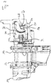
- the disc brake shown in the drawing includes a brake lining 10 on the application side and a brake lining 12 on the rim side, which lie on opposite sides of a brake disk not shown in the drawing.
- the main plane of the brake disc is, however, shown and provided with the reference symbol E.
- the disc brake also includes a caliper 14, which is a sliding caliper.
- a brake shaft belonging to an application device is designated by the reference number 16.
- the axis of rotation bears the reference symbol D.
- the brake shaft 16 On the side facing away from the brake lining 10 on the application side, the brake shaft 16 is supported on the brake caliper 14 via sliding blocks 18, 20.
- the sliding blocks each have a projection 22, 24, which is in a blind hole 26 or 28.
- the brake shaft 16 On the side facing the brake lining 10 on the application side, the brake shaft 16 is supported on a pressure piece 34 via rotary bearings 30, 32.
- the pressure piece 34 is supported by an adjusting screw 36 and a pressure ram 38 on the brake lining 10 on the application side.
- the pressure piece 34 has a first extension 40 and a second extension 42.
- a first stop 44 is formed on the first attachment 40, which interacts with a second stop 46 on the brake shaft 16 in such a way that it displaces the brake shaft parallel to its axis of rotation D in Figure 1 capped.
- a third stop 48 is formed on the second extension 42, which interacts with a fourth stop 50 on the brake shaft 16 in such a way that it moves the brake shaft 16 parallel to the axis of rotation D in Figure 1 limited down.
- a slight play is provided, which allows the brake shaft 16 to be rotated about the axis of rotation D, but at the same time the brake shaft 16 in the direction parallel to the axis of rotation D secures against displacement.
- the pressure piece 34 is also secured in the direction parallel to the axis of rotation D against displacement.
- a fifth stop 52, a sixth stop 54, a seventh stop 56 and an eighth stop 58 are used for this purpose.
- the fifth stop 52 and the seventh stop 56 are formed on the brake caliper 14 or are held immovably thereto, while the sixth stop 54 and the Eighth stop 58 are formed on the pressure piece 34, which is why the pressure piece 34 is held reliably in the direction parallel to the axis of rotation D.
- the fifth and the sixth stops 52, 54 represent a first restriction device for the displaceability of the pressure piece 34.
- the first attachment 40 with the first stop 44 and the second stop 46 represent represents a second restriction device for the displaceability of the brake shaft 16.
- the pressure piece 34 is secured against displacement with respect to the brake caliper 14 in the direction parallel to the axis of rotation D and the brake shaft 16 is secured against displacement with respect to the pressure piece 34 parallel to the axis of rotation D, the brake shaft 16 as a whole is against displacement with respect to of the brake caliper 14 secured in the direction parallel to the axis of rotation D, without it being necessary to attach or design corresponding stops, guide strips or the like in the inner region of the brake caliper 14 which is difficult to access, so that the manufacture of the brake is particularly simple.
- deformations of the brake caliper 14 which occur when the brake is applied in the area of the brake shaft 16, cannot impair the functional mobility of the brake shaft 16 because there are no guide strips or the like in this area.
- the deformations of the brake caliper 14 that usually occur when the brake is applied rather lead to an increase in the play between the fifth stop 52 and the sixth stop 54 or between the seventh stop 56 and the eighth stop 58, so that the brake is applied particularly reliably can.
- the application force is introduced into the pressure piece 34 by the brake shaft 16 via the rotary bearings 30 and 32.
- the outer edges of the rotary bearings 30 and 32 thus also represent the limits of the area B into which a braking force emanating from the brake shaft 16 is introduced into the pressure piece 34 during braking.
- the first approach 40 and the second approach 42 lie outside the area B mentioned, which brings considerable mechanical advantages.
- the distance a between the first attachment 40 and the second attachment 42 is greater than the distance b between the two outer edges of the rotary bearings 30, 32 which limit the area B of the application of the application force.
Landscapes
- Engineering & Computer Science (AREA)
- General Engineering & Computer Science (AREA)
- Mechanical Engineering (AREA)
- Transportation (AREA)
- Braking Arrangements (AREA)
Description
- Die Erfindung betrifft eine Scheibenbremse, insbesondere für Nutzfahrzeuge nach dem Oberbegriff von Anspruch 1 (
EP 1 160 447 ). - Ähnliche Scheibenbremsen sind beispielsweise aus der
CN 102 242 786 A und derDE 10 2010 005 909 A1 bekannt. Danach sind sogenannte Führungsleisten vorgesehen, die die Verschieblichkeit sowohl des Druckstücks als auch der Bremswelle bezüglich der Bremsscheibe in Richtung parallel zur Drehachse der Bremswelle auf ein vorbestimmtes Maß beschränken. Das vorbestimmte Maß liegt dabei bei Null bzw. nahe Null, weil die Führungsleisten - entsprechend ihrer Bezeichnung - das Druckstück bzw. die Bremswelle in Axialrichtung beim Bremsen bzw. Zuspannen der Bremsen führen sollen, gleichzeitig aber gewährleistet sein muss, dass die genannten Bauteile sich nicht verklemmen. - Bei den bekannten Scheibenbremsen liegt derjenige Teil der Führungsleisten, der die Verschieblichkeit der Bremswelle beschränken soll, tief im Inneren des Bremssattels, weshalb eine präzise Bearbeitung zur Sicherstellung der einwandfreien Funktion schwierig ist. Darüber hinaus wirkt eine Verformung der beteiligten Bremsenteile, insbesondere des Bremssattels, infolge der Zuspannung beim Bremsen im Sinne einer Verkleinerung des Spiels zwischen insbesondere der Bremswelle und dem einschlägigen Abschnitt der Führungsleiste, was zu einem Verklemmen führen kann.
- Der Erfindung liegt die Aufgabe zugrunde, die Scheibenbremse der eingangs genannten Art derart zu verbessern, dass zum einen die Herstellung vereinfacht ist und zum anderen ein Verklemmen infolge Verformungen beim Zuspannen vermieden ist.
- Erfindungsgemäß wird die gestellte Aufgabe mit einer Scheibenbremse nach Anspruch 1 gelöst.
- Mit anderen Worten wird die zweite Beschränkungseinrichtung, also diejenige Beschränkungseinrichtung, die die Verschieblichkeit der Bremswelle auf das vorbestimmte zweite Maß beschränkt, dadurch realisiert, dass die Verschieblichkeit der Bremswelle bezüglich des Druckstücks beschränkt wird. Die Beschränkungseinrichtung für das Druckstück kann dabei wie herkömmlich ausgestaltet sein. Mit anderen Worten wird die Verschieblichkeit des Druckstücks beschränkt, und die Bremswelle wird derart mit dem Druckstück gekoppelt, dass diese Verschieblichkeit nicht etwa absolut, sondern nur bezüglich des Druckstücks beschränkt ist. Im Ergebnis wird die gewünschte Verschieblichkeitsbeschränkung für beide Elemente, also sowohl für das Druckstück als auch für die Bremswelle erzielt, ohne dass beispielsweise im Inneren eines Bremssattels Führungsleisten für die Bremswelle vorgesehen werden müssten.
- Dadurch, dass die Führungsleisten für die Bremswelle entbehrlich sind, ist der Herstellungsaufwand verringert. Darüber hinaus besteht nicht die Gefahr des Verklemmens mit den genannten Führungsleisten. Im Gegenteil: Die Anschläge (erster Anschlag an dem Druckstück und zweiter Anschlag an der Bremswelle) werden sich wegen der gegebenen Geometrien infolge von Verformungen während des Zuspannens der Bremse im Sinne einer Spielvergrößerung verschieben, so dass ein Verklemmen zuverlässig ausgeschlossen ist.
- Aus der
EP 1 789 695 B1 ist eine Scheibenbremse bekannt, bei der nicht wie nach der vorliegenden Erfindung das Druckstück die Bremswelle hält, sondern umgekehrt die Bremswelle das Druckstück. Auch diese bekannte Scheibenbremse bringt die oben beschriebenen Probleme hinsichtlich des Herstellungsaufwands und hinsichtlich der Verklemmsicherheit mit sich. - Dabei kann erfindungsgemäß vorgesehen sein, dass der erste Anschlag außerhalb desjenigen Bereichs liegt, in den beim Bremsen eine von der Bremswelle ausgehende Zuspannkraft in das Druckstück eingeleitet wird. Diese Ausgestaltung hat erhebliche mechanische Vorteile.
- Erfindungsgemäß bevorzugt ist vorgesehen, dass die zweite Beschränkungseinrichtung einen, zwei oder mehr Ansätze an dem Druckstück aufweist. An einem solchen Ansatz (oder an mehreren Ansätzen) kann dann der erste Anschlag ausgebildet werden, mit dem der zweite Anschlag im Sinne eines Beschränkens der Verschieblichkeit der Bremswelle zusammenwirkt.
- Selbstverständlich kann im Sinne einer mechanischen Umkehr ein solcher Ansatz (oder auch zwei oder mehrere) an der Bremswelle ausgebildet sein, um den zweiten Anschlag zu realisieren.
- Im Falle von zwei Ansätzen kann es erfindungsgemäß vorgesehen sein, dass der Abstand der beiden Ansätze voneinander größer ist als der Abstand der in Richtung parallel zur Drehachse der Bremswelle gemessene Abstand der äußeren Ränder desjenigen Bereichs, in dem beim Bremsen eine von der Bremswelle ausgehende Zuspannkraft in das Druckstück eingeleitet wird.
- Mit anderen Worten liegen bei dieser Ausgestaltung der Erfindung die beiden Ansätze mit dem jeweiligen Anschlag weiter auseinander, als der Krafteinleitungsbereich breit ist. Wiederum werden mechanische Vorteile erzielt.
- Die erfindungsgemäße Scheibenbremse weist bevorzugt einen Bremssattel, insbesondere einen Gleitsattel auf. Mit anderen Worten handelt es sich bevorzugt um eine Gleitsattelscheibenbremse.
- Die Bremswelle stützt sich erfindungsgemäß bei Betätigung an dem Bremssattel ab, insbesondere an dessen Rückwand. Dadurch kann die Zuspannkraft auf einen auf der Felgenseite der Bremsscheibe gelegenen weiteren Bremsbelag übertragen werden.
- Die Abstützung der Bremswelle an dem Bremssattel erfolgt über einen Gleitstein. Ein solcher Gleitstein kann gegebenenfalls durch entsprechendes Gleiten ein Verklemmen der an der Zuspannung der Bremse beteiligten Elemente vermeiden.
- Erfindungsgemäß ist eine dritte Beschränkungseinrichtung vorgesehen, die die Verschieblichkeit des Gleitsteins bezüglich der Bremsscheibe in mindestens einer parallel zur Hauptebene der Bremsscheibe liegenden Richtung auf ein vorbestimmtes drittes Maß beschränkt. Eine solche Beschränkungseinrichtung kann insbesondere bei der Montage der Bremse hilfreich sein, nämlich beispielsweise als Verliersicherung für den Gleitstein.
- Dabei ist es erfindungsgemäß vorgesehen , dass die dritte Beschränkungseinrichtung einen Vorsprung aufweist, der in montiertem Zustand in eine Ausnehmung hineinragt.
- Dabei gibt es wiederum zwei Möglichkeiten: Der Vorsprung kann an dem Gleitstein ausgebildet sein, während die Ausnehmung an dem Bremssattel ausgebildet ist. Selbstverständlich geht es auch umgekehrt mit einer Ausnehmung an dem Gleitstein und einem Vorsprung an dem Bremssattel.
- Das vorbestimmte dritte Maß ist dabei wiederum derart zu wählen, dass nötigenfalls ausreichend Spiel für Ausgleichs-Gleitbewegungen vorhanden ist.
- Bei der Ausnehmung handelt es sich erfindungsgemäß um ein Sackloch.
- Im Folgenden ist die Erfindung anhand eines bevorzugten Ausführungsbeispiels unter Bezugnahme auf die beiliegende Zeichnung mit weiteren Einzelheiten näher erläutert. Dabei zeigen
- Figur 1
- eine schematische Schnittansicht eines bevorzugten Ausführungsbeispiels der erfindungsgemäßen Scheibenbremse von oben,
- Figur 2
- eine schematische Schnittansicht der Scheibenbremse nach
Figur 1 von der Seite, - Figur 3
- eine schematische perspektivische Ansicht der Zuspanneinrichtung der Scheibenbremse nach
Figur 1 und - Figur 4
- eine schematische perspektivische Ansicht eines Gleitsteins der Scheibenbremse nach
Figur 1 . - Zu der in der Zeichnung dargestellten Scheibenbremse gehören ein zuspannseitiger Bremsbelag 10 und ein felgenseitiger Bremsbelag 12, die auf einander gegenüberliegenden Seiten einer nicht in der Zeichnung dargestellten Bremsscheibe liegen. Die Hauptebene der Bremsscheibe ist jedoch eingezeichnet und mit dem Bezugszeichen E versehen. Ferner gehört zu der Scheibenbremse ein Bremssattel 14, bei dem es sich um einen Gleitsattel handelt. Eine zu einer Zuspanneinrichtung gehörende Bremswelle ist mit der Bezugszahl 16 bezeichnet. Ihre Drehachse trägt das Bezugszeichen D. Auf der dem zuspannseitigen Bremsbelag 10 abgewandten Seite stützt sich die Bremswelle 16 über Gleitsteine 18, 20 an dem Bremssattel 14 ab. Die Gleitsteine weisen jeweils einen Vorsprung 22, 24 auf, der in einem Sackloch 26 bzw. 28 steckt.
- Auf der dem zuspannseitigen Bremsbelag 10 zugewandten Seite stützt sich die Bremswelle 16 über Drehlager 30, 32 an einem Druckstück 34 ab. Das Druckstück 34 stützt sich über eine Nachstellschraube 36 und einen Druckstempel 38 an dem zuspannseitigen Bremsbelag 10 ab.
- Wird die Bremswelle 16 verdreht, so tritt wegen ihrer exzentrischen Ausgestaltung eine Spreizung auf, durch die die Drehlager 30, 32, das Druckstück 34, die Nachstellschraube 36, der Druckstempel 38 und schließlich der zuspannseitige Bremsbelag in
Figur 1 nach links gegen die Bremsscheibe gedrückt werden, wohingegen sich der Bremssattel 14 nach rechts bewegt und dadurch den felgenseitigen Bremsbelag 12 von der anderen Seite gegen die Bremsscheibe drückt. - Das Druckstück 34 weist einen ersten Ansatz 40 und einen zweiten Ansatz 42 auf. An dem ersten Ansatz 40 ist ein erster Anschlag 44 ausgebildet, der mit einem zweiten Anschlag 46 an der Bremswelle 16 derart zusammenwirkt, dass er eine Verschiebung der Bremswelle parallel zu ihrer Drehachse D in
Figur 1 nach oben beschränkt. - In gleicher Weise ist an dem zweiten Ansatz 42 ein dritter Anschlag 48 ausgebildet, der mit einem vierten Anschlag 50 an der Bremswelle 16 derart zusammenwirkt, dass er ein Verschieben der Bremswelle 16 parallel zur Drehachse D in
Figur 1 nach unten beschränkt. Zwischen dem ersten Anschlag 44 und dem zweiten Anschlag 46 bzw. zwischen dem dritten Anschlag 48 und dem vierten Anschlag 50 ist jeweils ein geringes Spiel vorgesehen, das zwar ein Verdrehen der Bremswelle 16 um die Drehachse D erlaubt, gleichzeitig aber die Bremswelle 16 in Richtung parallel zu der Drehachse D gegen Verschieben sichert. - Auch das Druckstück 34 ist in Richtung parallel zu der Drehachse D gegen Verschieben gesichert. Dazu dienen ein fünfter Anschlag 52, ein sechster Anschlag 54, ein siebter Anschlag 56 und ein achter Anschlag 58. Der fünfte Anschlag 52 und der siebte Anschlag 56 sind dabei an dem Bremssattel 14 ausgebildet oder unverschieblich dazu gehalten, während der sechste Anschlag 54 und der achte Anschlag 58 an dem Druckstück 34 ausgebildet sind, weshalb das Druckstück 34 in Richtung parallel zur Drehachse D zuverlässig gehalten ist. Wiederum gilt, dass ein Spiel zwischen dem fünften Anschlag 52 und dem sechsten Anschlag 54 bzw. zwischen dem siebten Anschlag 56 und dem achten Anschlag 58 derart beschaffen ist, dass zwar eine zuverlässige Verschiebesicherung gewährleistet ist, dennoch aber eine Bewegung des Druckstücks 34 in Rechts-Links-Richtung in
Figur 1 , also senkrecht zur Hauptebene E der Bremsscheibe gewährleistet ist. - Der fünfte und der sechste Anschlag 52, 54 stellen eine erste Beschränkungseinrichtung für die Verschieblichkeit des Druckstücks 34 dar. Das gleiche gilt für den siebten und den achten Anschlag 56, 58. Der erste Ansatz 40 mit dem ersten Anschlag 44 und der zweite Anschlag 46 stellen eine zweite Beschränkungseinrichtung für die Verschieblichkeit der Bremswelle 16 dar. Das gleiche gilt für den zweiten Ansatz 42 mit dem dritten Anschlag 48 und dem vierten Anschlag 50.
- Da entsprechend den obigen Darlegungen das Druckstück 34 gegen ein Verschieben bezüglich des Bremssattels 14 in Richtung parallel zur Drehachse D gesichert ist und die Bremswelle 16 gegen ein Verschieben bezüglich des Druckstücks 34 parallel zur Drehachse D gesichert ist, ist insgesamt die Bremswelle 16 gegen ein Verschieben bezüglich des Bremssattels 14 in Richtung parallel zur Drehachse D gesichert, ohne dass es erforderlich wäre, im schwer zugänglichen inneren Bereich des Bremssattels 14 entsprechende Anschläge, Führungsleisten oder dergleichen anzubringen oder auszubilden, so dass die Herstellung der Bremse besonders einfach ist. Darüber hinaus können Verformungen des Bremssattels 14, die beim Zuspannen der Bremse im Bereich der Bremswelle 16 auftreten, die funktionelle Beweglichkeit der Bremswelle 16 nicht beeinträchtigen, weil in diesem Bereich keine Führungsleisten oder dergleichen vorhanden sind. Im Gegenteil: Die beim Zuspannen üblicherweile auftretenden Verformungen des Bremssattels 14 führen vielmehr zu einer Vergrößerung des Spiels zwischen dem fünften Anschlag 52 und dem sechsten Anschlag 54 bzw. zwischen dem siebten Anschlag 56 und dem achten Anschlag 58, so dass die Bremse besonders zuverlässig zugespannt werden kann.
- Wie oben erläutert, wird die Zuspannkraft von der Bremswelle 16 über die Drehlager 30 und 32 in das Druckstück 34 eingeleitet. Die äußeren Ränder der Drehlager 30 und 32 stellen damit auch die Grenzen desjenigen Bereichs B dar, in den beim Bremsen eine von der Bremswelle 16 ausgehende Zuspannkraft in das Druckstück 34 eingeleitet wird. Der erste Ansatz 40 und der zweite Ansatz 42 liegen außerhalb des genannten Bereichs B, was erhebliche mechanische Vorteile mit sich bringt. Der Abstand a zwischen dem ersten Ansatz 40 und dem zweiten Ansatz 42 ist größer als der Abstand b der beiden genannten Außenränder der Drehlager 30, 32, die den genannten Bereich B der Zuspannkrafteinleitung begrenzen.
- Die in der obigen Beschreibung, den Ansprüchen sowie der Zeichnung offenbarten Merkmale der Erfindung können sowohl einzeln als auch in beliebigen Kombinationen für die Verwirklichung der Erfindung in ihren verschiedenen Ausführungsformen wesentlich sein.
Claims (4)
- Scheibenbremse, insbesondere für Nutzfahrzeuge, mit
einer Bremsscheibe,
einer Bremswelle (16), deren Drehachse (D) parallel zu einer Hauptebene (E) der Bremsscheibe liegt,
einem Bremssattel (14), insbesondere einem Gleitsattel, an dem sich die Bremswelle (16) bei Betätigung über einen Gleitstein (18, 20) abstützt,
einem bezüglich der Bremsscheibe auf derselben Seite wie die Bremswelle liegenden Bremsbelag (10),
einem Druckstück (34) zwischen der Bremswelle und dem Bremsbelag,
einer ersten Beschränkungseinrichtung (52, 54; 56, 58), die die Verschieblichkeit des Druckstücks bezüglich der Bremsscheibe in Richtung parallel zur Drehachse der Bremswelle auf ein vorbestimmtes erstes Maß beschränkt und
einer zweiten Beschränkungseinrichtung (40, 44, 46; 42, 48, 50), die die Verschieblichkeit der Bremswelle bezüglich der Bremsscheibe in Richtung parallel zur Drehachse der Bremswelle auf ein vorbestimmtes zweites Maß beschränkt, wobei
die Bremswelle bei Betätigung das Druckstück und damit den Bremsbelag gegen die Bremsscheibe drückt,
die zweite Beschränkungseinrichtung (40, 44, 46; 42, 48, 50) einen ersten Anschlag (44) an dem Druckstück (34) und einen mit dem ersten Anschlag im Sinne eines Beschränkens der Verschieblichkeit zusammenwirkenden zweiten Anschlag (46) an der Bremswelle (16) aufweist,
eine dritte Beschränkungseinrichtung (22, 24; 26, 28) vorgesehen ist, die die Verschieblichkeit des Gleitsteins (18, 20) bezüglich der Bremsscheibe in mindestens einer parallel zur Hauptebene (E) der Bremsscheibe liegenden Richtung auf ein vorbestimmtes drittes Maß beschränkt und
die dritte Beschränkungseinrichtung (22, 24; 26, 28) einen Vorsprung (22; 24) aufweist, der in montiertem Zustand in eine Ausnehmung (26; 28) hineinragt,
dadurch gekennzeichnet, dass
die Ausnehmung (26; 28) ein Sackloch ist. - Scheibenbremse nach Anspruch 1, dadurch gekennzeichnet, dass der erste Anschlag (44) außerhalb desjenigen Bereichs (B) liegt, in dem beim Bremsen eine von der Bremswelle (16) ausgehende Zuspannkraft in das Druckstück (34) eingeleitet wird.
- Scheibenbremse nach Anspruch 1 oder 2, dadurch gekennzeichnet, dass die zweite Beschränkungseinrichtung (40, 44, 46; 42, 48, 50) einen, zwei oder mehr Ansätze (40, 42) an dem Druckstück (34) aufweist.
- Scheibenbremse nach Anspruch 3, dadurch gekennzeichnet, dass im Falle von zwei Ansätzen (40, 42) der Abstand (a) der beiden Ansätze voneinander größer ist als der in Richtung parallel zur Drehachse (D) der Bremswelle (10) gemessene Abstand (b) der äußeren Ränder desjenigen Bereichs (B), in dem beim Bremsen eine von der Bremswelle ausgehende Zuspannkraft in das Druckstück (34) eingeleitet wird.
Priority Applications (4)
| Application Number | Priority Date | Filing Date | Title |
|---|---|---|---|
| EP15001864.6A EP3109499B1 (de) | 2015-06-23 | 2015-06-23 | Scheibenbremse, insbesondere für nutzfahrzeuge |
| PCT/EP2016/000935 WO2016206778A1 (de) | 2015-06-23 | 2016-06-06 | Scheibenbremse, insbesondere für nutzfahrzeuge |
| CN201680022801.5A CN107532667B (zh) | 2015-06-23 | 2016-06-06 | 盘式制动器 |
| US15/578,713 US10634201B2 (en) | 2015-06-23 | 2016-06-06 | Disc brake, more particularly for commercial vehicles |
Applications Claiming Priority (1)
| Application Number | Priority Date | Filing Date | Title |
|---|---|---|---|
| EP15001864.6A EP3109499B1 (de) | 2015-06-23 | 2015-06-23 | Scheibenbremse, insbesondere für nutzfahrzeuge |
Publications (2)
| Publication Number | Publication Date |
|---|---|
| EP3109499A1 EP3109499A1 (de) | 2016-12-28 |
| EP3109499B1 true EP3109499B1 (de) | 2019-12-25 |
Family
ID=53488107
Family Applications (1)
| Application Number | Title | Priority Date | Filing Date |
|---|---|---|---|
| EP15001864.6A Active EP3109499B1 (de) | 2015-06-23 | 2015-06-23 | Scheibenbremse, insbesondere für nutzfahrzeuge |
Country Status (4)
| Country | Link |
|---|---|
| US (1) | US10634201B2 (de) |
| EP (1) | EP3109499B1 (de) |
| CN (1) | CN107532667B (de) |
| WO (1) | WO2016206778A1 (de) |
Families Citing this family (4)
| Publication number | Priority date | Publication date | Assignee | Title |
|---|---|---|---|---|
| DE102017116112A1 (de) * | 2017-07-18 | 2019-01-24 | Bpw Bergische Achsen Kg | Scheibenbremse mit darin angeordneter Zuspannvorrichtung sowie Stützrolle für die Zuspannvorrichtung |
| EP3772599B1 (de) | 2019-08-05 | 2024-05-01 | ZF CV Systems Europe BV | Bremssattel für eine fahrzeugbremse und verfahren zur montage eines bremssattels |
| DE102020006379A1 (de) * | 2019-10-18 | 2021-04-22 | Haldex Brake Products Ab | Scheibenbremse und Herstellungsverfahren für eine Scheibenbremse |
| DE102023119861A1 (de) | 2023-07-26 | 2025-01-30 | Zf Cv Systems Europe Bv | Gleitlagerkomponente für eine Zuspannvorrichtung einer Scheibenbremse für ein Fahrzeug, insbesondere Nutzfahrzeug, Bremssattel, Scheibenbremse und Fahrzeug |
Citations (2)
| Publication number | Priority date | Publication date | Assignee | Title |
|---|---|---|---|---|
| WO1996012900A1 (en) * | 1994-10-24 | 1996-05-02 | Haldex Ab | A disc brake caliper |
| WO2015040652A1 (ja) * | 2013-09-19 | 2015-03-26 | 株式会社Tbk | ディスクブレーキ装置 |
Family Cites Families (17)
| Publication number | Priority date | Publication date | Assignee | Title |
|---|---|---|---|---|
| US5379867A (en) | 1992-05-08 | 1995-01-10 | Deutsche Perrot-Bremse Gmbh | Re-adjusting mechanism for a disc brake |
| DE59508013D1 (de) * | 1994-01-18 | 2000-04-20 | Meritor Automotive Inc | Zuspannvorrichtung einer Scheibenbremse, insbesondere für schwere Nutzfahrzeuge |
| GB9716363D0 (en) * | 1997-08-02 | 1997-10-08 | Lucas Ind Plc | Improvements relating to disc brakes |
| SE516495C2 (sv) * | 2000-05-31 | 2002-01-22 | Haldex Brake Prod Ab | Bromsmekanism och bromsok för en skivbroms |
| DE102004042576A1 (de) | 2004-09-02 | 2006-03-30 | Knorr-Bremse Systeme für Nutzfahrzeuge GmbH | Scheibenbremse für ein Fahrzeug, insbesondere ein Nutzfahrzeug |
| CN201096156Y (zh) * | 2007-09-12 | 2008-08-06 | 内蒙古北方重型汽车股份有限公司 | 井下防爆工程自卸车液压盘式制动器装置 |
| ATE531968T1 (de) * | 2008-08-14 | 2011-11-15 | Wabco Radbremsen Gmbh | Scheibenbremse |
| DE102009023416A1 (de) * | 2009-05-29 | 2010-12-23 | Knorr-Bremse Systeme für Nutzfahrzeuge GmbH | Pneumatisch oder elektromechanisch betätigbare Scheibenbremse |
| DE102010005909C5 (de) | 2010-01-27 | 2017-02-16 | Wabco Europe Bvba-Sprl | Scheibenbremse, insbesondere für Nutzfahrzeuge |
| CN102242786A (zh) * | 2011-07-13 | 2011-11-16 | 浙江万安科技股份有限公司 | 一种气压盘式制动器 |
| CN202295176U (zh) * | 2011-11-03 | 2012-07-04 | 时利 | 一种双作用自行车碟刹装置 |
| CN102518721A (zh) * | 2012-01-13 | 2012-06-27 | 冠亚机械工业(昆山)有限公司 | 盘式制动器 |
| DE202014002459U1 (de) * | 2014-03-19 | 2014-04-17 | Haldex Brake Products Ab | Scheibenbremse und Bremsbetätigungsmechanismus für eine Scheibenbremse |
| DE102014112241A1 (de) * | 2014-08-26 | 2016-03-03 | Bpw Bergische Achsen Kg | Lagerung eines mit einem Schwenkarm versehenen Hebels gegenüber einem Druckstück |
| DE102014017430A1 (de) * | 2014-11-25 | 2016-05-25 | Wabco Europe Bvba | Scheibenbremse, insbesondere für Nutzfahrzeuge |
| DE102014017438A1 (de) * | 2014-11-25 | 2016-05-25 | Wabco Europe Bvba | Scheibenbremse. insbesondere für Nutzfahrzeuge |
| DE102015013240A1 (de) * | 2015-10-12 | 2017-04-13 | Wabco Europe Bvba | Scheibenbremse, insbesondere für Nutzfahrzeuge |
-
2015
- 2015-06-23 EP EP15001864.6A patent/EP3109499B1/de active Active
-
2016
- 2016-06-06 US US15/578,713 patent/US10634201B2/en active Active
- 2016-06-06 CN CN201680022801.5A patent/CN107532667B/zh active Active
- 2016-06-06 WO PCT/EP2016/000935 patent/WO2016206778A1/de not_active Ceased
Patent Citations (3)
| Publication number | Priority date | Publication date | Assignee | Title |
|---|---|---|---|---|
| WO1996012900A1 (en) * | 1994-10-24 | 1996-05-02 | Haldex Ab | A disc brake caliper |
| WO2015040652A1 (ja) * | 2013-09-19 | 2015-03-26 | 株式会社Tbk | ディスクブレーキ装置 |
| EP3048324A1 (de) * | 2013-09-19 | 2016-07-27 | TBK Co., Ltd. | Scheibenbremsenvorrichtung |
Also Published As
| Publication number | Publication date |
|---|---|
| EP3109499A1 (de) | 2016-12-28 |
| WO2016206778A1 (de) | 2016-12-29 |
| CN107532667B (zh) | 2020-08-07 |
| CN107532667A (zh) | 2018-01-02 |
| US20180106307A1 (en) | 2018-04-19 |
| US10634201B2 (en) | 2020-04-28 |
Similar Documents
| Publication | Publication Date | Title |
|---|---|---|
| EP3020998B2 (de) | Scheibenbremse | |
| EP2997278B2 (de) | Sattelscheibenbremse eines fahrzeugs | |
| EP1982087B1 (de) | Scheibenbremse und bremsbelag für eine scheibenbremse, insbesondere für ein nutzfahrzeug | |
| EP2761201B1 (de) | Scheibenbremse, insbesondere für nutzfahrzeuge, sowie niederhaltefeder einer solchen scheibenbremse | |
| DE102012209341B4 (de) | Bremszange | |
| DE112016000657T5 (de) | Bremsclip für scheibenbremsanordnung und eine einen solchen bremsclip umfassende scheibenbremsanordnung | |
| WO2016206778A1 (de) | Scheibenbremse, insbesondere für nutzfahrzeuge | |
| EP3344895A1 (de) | Scheibenbremse mit synchronisationseinheit | |
| DE102004045218B4 (de) | Bremsenträger und scheibenbremse mit einem solchen bremsenträger | |
| EP3027926B1 (de) | Scheibenbremse, insbesondere für nutzfahrzeuge, sowie bremsbelag einer solchen scheibenbremse | |
| EP0681662B1 (de) | Befestigungsvorrichtung für scheibenbremsen | |
| DE102004052541B4 (de) | Bremssattel für eine Scheibenbremse | |
| WO2016107666A1 (de) | Scheibenbremse, insbesondere für nutzfahrzeuge | |
| DE102015002892A1 (de) | Achse eines Landfahrzeugs, Landfahrzeug mit einer solchen Achse sowie Scheibenbremse und Bremsenträger eines solchen Landfahrzeugs | |
| EP2334524B1 (de) | Pneumatische bremseinrichtung | |
| WO2013079376A2 (de) | Funktionseinheit zum nachstellen eines bremsbelages einer scheibenbremse | |
| EP2420690A1 (de) | Scheibenbremse, insbesondere für ein Nutzfahrzeug | |
| DE2756856A1 (de) | Schwimmsattel-scheibenbremse | |
| EP3625474B1 (de) | Anordnung einer scheibenbremse für ein nutzfahrzeug | |
| DE102005054402B4 (de) | Scheibenbremse, insbesondere für ein Nutzfahrzeug | |
| DE10242231B4 (de) | Trommelbremse | |
| DE102007040586B4 (de) | Bremsvorrichtung sowie Bremsenträger für eine solche Bremsvorrichtung | |
| WO2013159838A1 (de) | Trägerrahmendichtung mit verringertem platzbedarf | |
| DE102012220437B4 (de) | Seilklemmeinrichtung | |
| EP3146228B2 (de) | Trägereinheit |
Legal Events
| Date | Code | Title | Description |
|---|---|---|---|
| PUAI | Public reference made under article 153(3) epc to a published international application that has entered the european phase |
Free format text: ORIGINAL CODE: 0009012 |
|
| STAA | Information on the status of an ep patent application or granted ep patent |
Free format text: STATUS: THE APPLICATION HAS BEEN PUBLISHED |
|
| AK | Designated contracting states |
Kind code of ref document: A1 Designated state(s): AL AT BE BG CH CY CZ DE DK EE ES FI FR GB GR HR HU IE IS IT LI LT LU LV MC MK MT NL NO PL PT RO RS SE SI SK SM TR |
|
| AX | Request for extension of the european patent |
Extension state: BA ME |
|
| STAA | Information on the status of an ep patent application or granted ep patent |
Free format text: STATUS: REQUEST FOR EXAMINATION WAS MADE |
|
| 17P | Request for examination filed |
Effective date: 20170302 |
|
| STAA | Information on the status of an ep patent application or granted ep patent |
Free format text: STATUS: EXAMINATION IS IN PROGRESS |
|
| 17Q | First examination report despatched |
Effective date: 20180612 |
|
| GRAP | Despatch of communication of intention to grant a patent |
Free format text: ORIGINAL CODE: EPIDOSNIGR1 |
|
| STAA | Information on the status of an ep patent application or granted ep patent |
Free format text: STATUS: GRANT OF PATENT IS INTENDED |
|
| INTG | Intention to grant announced |
Effective date: 20190917 |
|
| GRAS | Grant fee paid |
Free format text: ORIGINAL CODE: EPIDOSNIGR3 |
|
| GRAA | (expected) grant |
Free format text: ORIGINAL CODE: 0009210 |
|
| STAA | Information on the status of an ep patent application or granted ep patent |
Free format text: STATUS: THE PATENT HAS BEEN GRANTED |
|
| AK | Designated contracting states |
Kind code of ref document: B1 Designated state(s): AL AT BE BG CH CY CZ DE DK EE ES FI FR GB GR HR HU IE IS IT LI LT LU LV MC MK MT NL NO PL PT RO RS SE SI SK SM TR |
|
| REG | Reference to a national code |
Ref country code: GB Ref legal event code: FG4D Free format text: NOT ENGLISH |
|
| REG | Reference to a national code |
Ref country code: CH Ref legal event code: EP |
|
| REG | Reference to a national code |
Ref country code: AT Ref legal event code: REF Ref document number: 1217458 Country of ref document: AT Kind code of ref document: T Effective date: 20200115 |
|
| REG | Reference to a national code |
Ref country code: DE Ref legal event code: R096 Ref document number: 502015011290 Country of ref document: DE |
|
| REG | Reference to a national code |
Ref country code: IE Ref legal event code: FG4D Free format text: LANGUAGE OF EP DOCUMENT: GERMAN |
|
| REG | Reference to a national code |
Ref country code: NL Ref legal event code: MP Effective date: 20191225 |
|
| PG25 | Lapsed in a contracting state [announced via postgrant information from national office to epo] |
Ref country code: LT Free format text: LAPSE BECAUSE OF FAILURE TO SUBMIT A TRANSLATION OF THE DESCRIPTION OR TO PAY THE FEE WITHIN THE PRESCRIBED TIME-LIMIT Effective date: 20191225 Ref country code: NO Free format text: LAPSE BECAUSE OF FAILURE TO SUBMIT A TRANSLATION OF THE DESCRIPTION OR TO PAY THE FEE WITHIN THE PRESCRIBED TIME-LIMIT Effective date: 20200325 Ref country code: GR Free format text: LAPSE BECAUSE OF FAILURE TO SUBMIT A TRANSLATION OF THE DESCRIPTION OR TO PAY THE FEE WITHIN THE PRESCRIBED TIME-LIMIT Effective date: 20200326 Ref country code: BG Free format text: LAPSE BECAUSE OF FAILURE TO SUBMIT A TRANSLATION OF THE DESCRIPTION OR TO PAY THE FEE WITHIN THE PRESCRIBED TIME-LIMIT Effective date: 20200325 Ref country code: SE Free format text: LAPSE BECAUSE OF FAILURE TO SUBMIT A TRANSLATION OF THE DESCRIPTION OR TO PAY THE FEE WITHIN THE PRESCRIBED TIME-LIMIT Effective date: 20191225 Ref country code: LV Free format text: LAPSE BECAUSE OF FAILURE TO SUBMIT A TRANSLATION OF THE DESCRIPTION OR TO PAY THE FEE WITHIN THE PRESCRIBED TIME-LIMIT Effective date: 20191225 Ref country code: FI Free format text: LAPSE BECAUSE OF FAILURE TO SUBMIT A TRANSLATION OF THE DESCRIPTION OR TO PAY THE FEE WITHIN THE PRESCRIBED TIME-LIMIT Effective date: 20191225 |
|
| REG | Reference to a national code |
Ref country code: LT Ref legal event code: MG4D |
|
| PG25 | Lapsed in a contracting state [announced via postgrant information from national office to epo] |
Ref country code: RS Free format text: LAPSE BECAUSE OF FAILURE TO SUBMIT A TRANSLATION OF THE DESCRIPTION OR TO PAY THE FEE WITHIN THE PRESCRIBED TIME-LIMIT Effective date: 20191225 Ref country code: HR Free format text: LAPSE BECAUSE OF FAILURE TO SUBMIT A TRANSLATION OF THE DESCRIPTION OR TO PAY THE FEE WITHIN THE PRESCRIBED TIME-LIMIT Effective date: 20191225 |
|
| PG25 | Lapsed in a contracting state [announced via postgrant information from national office to epo] |
Ref country code: AL Free format text: LAPSE BECAUSE OF FAILURE TO SUBMIT A TRANSLATION OF THE DESCRIPTION OR TO PAY THE FEE WITHIN THE PRESCRIBED TIME-LIMIT Effective date: 20191225 |
|
| PG25 | Lapsed in a contracting state [announced via postgrant information from national office to epo] |
Ref country code: EE Free format text: LAPSE BECAUSE OF FAILURE TO SUBMIT A TRANSLATION OF THE DESCRIPTION OR TO PAY THE FEE WITHIN THE PRESCRIBED TIME-LIMIT Effective date: 20191225 Ref country code: PT Free format text: LAPSE BECAUSE OF FAILURE TO SUBMIT A TRANSLATION OF THE DESCRIPTION OR TO PAY THE FEE WITHIN THE PRESCRIBED TIME-LIMIT Effective date: 20200520 Ref country code: NL Free format text: LAPSE BECAUSE OF FAILURE TO SUBMIT A TRANSLATION OF THE DESCRIPTION OR TO PAY THE FEE WITHIN THE PRESCRIBED TIME-LIMIT Effective date: 20191225 Ref country code: CZ Free format text: LAPSE BECAUSE OF FAILURE TO SUBMIT A TRANSLATION OF THE DESCRIPTION OR TO PAY THE FEE WITHIN THE PRESCRIBED TIME-LIMIT Effective date: 20191225 Ref country code: RO Free format text: LAPSE BECAUSE OF FAILURE TO SUBMIT A TRANSLATION OF THE DESCRIPTION OR TO PAY THE FEE WITHIN THE PRESCRIBED TIME-LIMIT Effective date: 20191225 |
|
| PG25 | Lapsed in a contracting state [announced via postgrant information from national office to epo] |
Ref country code: SM Free format text: LAPSE BECAUSE OF FAILURE TO SUBMIT A TRANSLATION OF THE DESCRIPTION OR TO PAY THE FEE WITHIN THE PRESCRIBED TIME-LIMIT Effective date: 20191225 Ref country code: IS Free format text: LAPSE BECAUSE OF FAILURE TO SUBMIT A TRANSLATION OF THE DESCRIPTION OR TO PAY THE FEE WITHIN THE PRESCRIBED TIME-LIMIT Effective date: 20200425 Ref country code: SK Free format text: LAPSE BECAUSE OF FAILURE TO SUBMIT A TRANSLATION OF THE DESCRIPTION OR TO PAY THE FEE WITHIN THE PRESCRIBED TIME-LIMIT Effective date: 20191225 |
|
| REG | Reference to a national code |
Ref country code: DE Ref legal event code: R097 Ref document number: 502015011290 Country of ref document: DE |
|
| PG25 | Lapsed in a contracting state [announced via postgrant information from national office to epo] |
Ref country code: ES Free format text: LAPSE BECAUSE OF FAILURE TO SUBMIT A TRANSLATION OF THE DESCRIPTION OR TO PAY THE FEE WITHIN THE PRESCRIBED TIME-LIMIT Effective date: 20191225 Ref country code: DK Free format text: LAPSE BECAUSE OF FAILURE TO SUBMIT A TRANSLATION OF THE DESCRIPTION OR TO PAY THE FEE WITHIN THE PRESCRIBED TIME-LIMIT Effective date: 20191225 |
|
| PLBE | No opposition filed within time limit |
Free format text: ORIGINAL CODE: 0009261 |
|
| STAA | Information on the status of an ep patent application or granted ep patent |
Free format text: STATUS: NO OPPOSITION FILED WITHIN TIME LIMIT |
|
| PG25 | Lapsed in a contracting state [announced via postgrant information from national office to epo] |
Ref country code: SI Free format text: LAPSE BECAUSE OF FAILURE TO SUBMIT A TRANSLATION OF THE DESCRIPTION OR TO PAY THE FEE WITHIN THE PRESCRIBED TIME-LIMIT Effective date: 20191225 |
|
| 26N | No opposition filed |
Effective date: 20200928 |
|
| PG25 | Lapsed in a contracting state [announced via postgrant information from national office to epo] |
Ref country code: MC Free format text: LAPSE BECAUSE OF FAILURE TO SUBMIT A TRANSLATION OF THE DESCRIPTION OR TO PAY THE FEE WITHIN THE PRESCRIBED TIME-LIMIT Effective date: 20191225 Ref country code: IT Free format text: LAPSE BECAUSE OF FAILURE TO SUBMIT A TRANSLATION OF THE DESCRIPTION OR TO PAY THE FEE WITHIN THE PRESCRIBED TIME-LIMIT Effective date: 20191225 |
|
| REG | Reference to a national code |
Ref country code: CH Ref legal event code: PL |
|
| PG25 | Lapsed in a contracting state [announced via postgrant information from national office to epo] |
Ref country code: PL Free format text: LAPSE BECAUSE OF FAILURE TO SUBMIT A TRANSLATION OF THE DESCRIPTION OR TO PAY THE FEE WITHIN THE PRESCRIBED TIME-LIMIT Effective date: 20191225 |
|
| PG25 | Lapsed in a contracting state [announced via postgrant information from national office to epo] |
Ref country code: LU Free format text: LAPSE BECAUSE OF NON-PAYMENT OF DUE FEES Effective date: 20200623 |
|
| REG | Reference to a national code |
Ref country code: BE Ref legal event code: MM Effective date: 20200630 |
|
| PG25 | Lapsed in a contracting state [announced via postgrant information from national office to epo] |
Ref country code: LI Free format text: LAPSE BECAUSE OF NON-PAYMENT OF DUE FEES Effective date: 20200630 Ref country code: FR Free format text: LAPSE BECAUSE OF NON-PAYMENT OF DUE FEES Effective date: 20200630 Ref country code: IE Free format text: LAPSE BECAUSE OF NON-PAYMENT OF DUE FEES Effective date: 20200623 Ref country code: CH Free format text: LAPSE BECAUSE OF NON-PAYMENT OF DUE FEES Effective date: 20200630 |
|
| PG25 | Lapsed in a contracting state [announced via postgrant information from national office to epo] |
Ref country code: BE Free format text: LAPSE BECAUSE OF NON-PAYMENT OF DUE FEES Effective date: 20200630 |
|
| REG | Reference to a national code |
Ref country code: AT Ref legal event code: MM01 Ref document number: 1217458 Country of ref document: AT Kind code of ref document: T Effective date: 20200623 |
|
| PG25 | Lapsed in a contracting state [announced via postgrant information from national office to epo] |
Ref country code: AT Free format text: LAPSE BECAUSE OF NON-PAYMENT OF DUE FEES Effective date: 20200623 |
|
| PG25 | Lapsed in a contracting state [announced via postgrant information from national office to epo] |
Ref country code: TR Free format text: LAPSE BECAUSE OF FAILURE TO SUBMIT A TRANSLATION OF THE DESCRIPTION OR TO PAY THE FEE WITHIN THE PRESCRIBED TIME-LIMIT Effective date: 20191225 Ref country code: MT Free format text: LAPSE BECAUSE OF FAILURE TO SUBMIT A TRANSLATION OF THE DESCRIPTION OR TO PAY THE FEE WITHIN THE PRESCRIBED TIME-LIMIT Effective date: 20191225 Ref country code: CY Free format text: LAPSE BECAUSE OF FAILURE TO SUBMIT A TRANSLATION OF THE DESCRIPTION OR TO PAY THE FEE WITHIN THE PRESCRIBED TIME-LIMIT Effective date: 20191225 |
|
| PG25 | Lapsed in a contracting state [announced via postgrant information from national office to epo] |
Ref country code: MK Free format text: LAPSE BECAUSE OF FAILURE TO SUBMIT A TRANSLATION OF THE DESCRIPTION OR TO PAY THE FEE WITHIN THE PRESCRIBED TIME-LIMIT Effective date: 20191225 |
|
| P01 | Opt-out of the competence of the unified patent court (upc) registered |
Effective date: 20230528 |
|
| REG | Reference to a national code |
Ref country code: DE Ref legal event code: R081 Ref document number: 502015011290 Country of ref document: DE Owner name: ZF CV SYSTEMS EUROPE BV, BE Free format text: FORMER OWNER: WABCO EUROPE BVBA, BRUESSEL, BE Ref country code: DE Ref legal event code: R082 Ref document number: 502015011290 Country of ref document: DE Representative=s name: SCHAEFERJOHANN, VOLKER WILLI, DIPL.-PHYS., DE |
|
| PGFP | Annual fee paid to national office [announced via postgrant information from national office to epo] |
Ref country code: GB Payment date: 20260409 Year of fee payment: 12 |
|
| PGFP | Annual fee paid to national office [announced via postgrant information from national office to epo] |
Ref country code: DE Payment date: 20260402 Year of fee payment: 12 |