EP3108951A1 - Luftfilteranlage - Google Patents
Luftfilteranlage Download PDFInfo
- Publication number
- EP3108951A1 EP3108951A1 EP16020245.3A EP16020245A EP3108951A1 EP 3108951 A1 EP3108951 A1 EP 3108951A1 EP 16020245 A EP16020245 A EP 16020245A EP 3108951 A1 EP3108951 A1 EP 3108951A1
- Authority
- EP
- European Patent Office
- Prior art keywords
- air
- separator
- vertical
- air filter
- filter system
- Prior art date
- Legal status (The legal status is an assumption and is not a legal conclusion. Google has not performed a legal analysis and makes no representation as to the accuracy of the status listed.)
- Granted
Links
Images


Classifications
-
- B—PERFORMING OPERATIONS; TRANSPORTING
- B01—PHYSICAL OR CHEMICAL PROCESSES OR APPARATUS IN GENERAL
- B01D—SEPARATION
- B01D45/00—Separating dispersed particles from gases or vapours by gravity, inertia, or centrifugal forces
- B01D45/04—Separating dispersed particles from gases or vapours by gravity, inertia, or centrifugal forces by utilising inertia
- B01D45/06—Separating dispersed particles from gases or vapours by gravity, inertia, or centrifugal forces by utilising inertia by reversal of direction of flow
-
- B—PERFORMING OPERATIONS; TRANSPORTING
- B01—PHYSICAL OR CHEMICAL PROCESSES OR APPARATUS IN GENERAL
- B01D—SEPARATION
- B01D45/00—Separating dispersed particles from gases or vapours by gravity, inertia, or centrifugal forces
- B01D45/04—Separating dispersed particles from gases or vapours by gravity, inertia, or centrifugal forces by utilising inertia
- B01D45/08—Separating dispersed particles from gases or vapours by gravity, inertia, or centrifugal forces by utilising inertia by impingement against baffle separators
-
- B—PERFORMING OPERATIONS; TRANSPORTING
- B01—PHYSICAL OR CHEMICAL PROCESSES OR APPARATUS IN GENERAL
- B01D—SEPARATION
- B01D46/00—Filters or filtering processes specially modified for separating dispersed particles from gases or vapours
- B01D46/24—Particle separators, e.g. dust precipitators, using rigid hollow filter bodies
- B01D46/2403—Particle separators, e.g. dust precipitators, using rigid hollow filter bodies characterised by the physical shape or structure of the filtering element
-
- B—PERFORMING OPERATIONS; TRANSPORTING
- B01—PHYSICAL OR CHEMICAL PROCESSES OR APPARATUS IN GENERAL
- B01D—SEPARATION
- B01D50/00—Combinations of methods or devices for separating particles from gases or vapours
- B01D50/20—Combinations of devices covered by groups B01D45/00 and B01D46/00
Definitions
- the invention relates to an air filter system with a vertical structure.
- a high particle content leads to premature clogging of the filter provided in such extraction systems.
- air is problematic that these may still contain hot or glowing particles and particles, which can lead to burnup of the filter or the air flow exposed parts such as hoses or the like of the system.
- From the DE 25 33 827 A1 is an apparatus for separating liquid droplets and solid particles from a gas stream with a plurality of Abscheidellamellen, known, wherein the leading edges of the Abscheidelamellen are provided with gutters, which are arranged offset from each other.
- FR2778580A1 and the JPHO3-146108A is a filter unit known in the interior of a plurality of sheets offset side by side and arranged one above the other.
- a cylindrical filter element is known that can adjust the water flow rate through it so that it can be used in different regions.
- the object of the invention is therefore to provide an air filter system in which a simple and compact construction enables the most effective selection of particles possible.
- an air filter system with a vertical structure wherein at the upper part of the system a suction is provided can be sucked through the loaded with particles to be separated air, wherein in the interior of the plant a vertical channel is provided by which sucked polluted air inside the plant after is guided below, wherein the vertical channel in the lower part of the system laterally has an opening through which the air flow is directed to a arranged in the region of the opening Materialvorabscheider and is passed therethrough, wherein in the air path to the material pre-separator a process space is provided in the the air flow passes to the material pre-separator, wherein one or more filter bodies is / are arranged in the process space, wherein a blower driving the air flow is provided in the air path to the process space, which is characterized in that the material pre-separator e entrance side and one exit side for a particle-laden air flow and consists of a plurality of vertically stacked strip-shaped separation elements, wherein the separation elements are arranged
- a collecting tray is provided under the vertical channel and / or the particle impact, which is designed in particular similar to a drawer. hereby Maintenance and emptying of the system is very easy.
- the arrangement of the separation elements of the air flow is deflected targeted. This achieves separation of the fractions (air and particles contained therein). This has the consequence that the air flow is cleaned.
- At least one of the separation elements has at its lower edge a lower groove opening to the exit side.
- at least one of the separation elements on its upper edge on an upper channel, which opens to the entrance side.
- the angle of employment of the separation elements to the vertical between 21 ° to 31 °, as well as selected between 31 ° and 41 ° and between -7 ° to -13 °.
- a preferred embodiment of the invention provides that the separation elements are seen from the inlet side with an overlap behind and below each other.
- a variant of the invention provides that two separation elements are arranged one above the other at the same angle of attack against the vertical.
- the material pre-separator is preferably flowed on the inlet side from the front and / or from above.
- the separation elements are formed by sheets.
- a particularly advantageous embodiment of the invention provides that the opening width of the lower edge of the separating elements is reduced from separating element to separating element against a common vertical from above and widens again at the lowest separating element.
- Fig. 1 is a schematic sectional view through an air filter system 7 according to the invention shown.
- Fig. 1 and 2 shows an exemplary air filter system 7 with a vertical structure, wherein at the top of the system on the upper side of the housing, a suction port 71 is provided through which can be sucked with particle-laden air.
- Fig. 1 The inner structure of the system is shown in more detail.
- a vertical channel 72 is provided through which the sucked loaded air inside the system is guided vertically downwards, the vertical channel 72 in the lower part of the system laterally has an opening 73 through which the air flow (shown by the arrows) is directed to a arranged in the region of the opening Materialvorabscheider 1, which is formed from the deposition elements 5, 2, 3 and 4, is guided and is passed therethrough.
- the drip tray 76 is designed similar to an outwardly extendable drawer.
- a process space 74 is provided into which the air flow passes to the material pre-separator.
- a plurality of filter bodies 77 are arranged in the process chamber 74, wherein the air flow through the filter body 77 through the above arranged, the air flow driving, fan 75 is withdrawn.
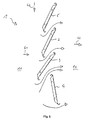
- Fig. 3 an explanatory side view of the material pre-separator 1 is shown, the particle-laden air stream can flow through the material pre-separator 1 from an inlet side 11 to an outlet side 12.
- deposition elements 5, 2, 3, 4 - formed in the example by sheets - arranged vertically one above the other.
- the separation elements 5, 2, 3, 4 are strip-shaped and seen from the inlet side 11 ago with an overlap behind and arranged below each other (see also Fig. 4 ).
- the separation elements 2, 3 and 4 form the central group of Materialvorabscheiders.
- the separation elements 2, 3 are arranged from top to bottom first with a rising positive angle W2, W3 against the vertical V and a lower separation element 4 has at a negative angle W4 against the vertical V.
- angles of employment of the separation elements 2, 3 and 4 to the vertical are in the example to 26 °, 36 ° and -10 ° has been chosen. These angles have been shown to be very effective in experiments.
- a separating element 5 has additionally been provided with the same angle of attack against the vertical above the separating element 2 arranged underneath.
- the separating elements 2, 3, 4, 5 have at their lower edge a lower channel 21, 31, 41, 51 which opens to the exit side 12. Also, the separation elements 2, 3, 4, 5 at its upper edge an upper channel 22, 32, 42, 52 which opens to the inlet side 11 towards.
- the air is forced to redirect again due to the edging, which in turn leads to further particles being able to be separated off.
- FIG. 5 is appropriate
- Fig. 3 illustrates that the opening width A1 to A3 of the lower edge of the separation elements 5, 2, 3, 4 against a common vertical V seen from above decreases from separation element to separation element 5, 2, 3 and widens again at the lowest deposition element 4 (A4 ).
- Fig. 6 shows again the air flow path from the intake at the inlet side 11 from the front 61 and mainly from above 62 and the discharge 63 at the exit side 12.
Abstract
Description
- Die Erfindung betrifft eine Luftfilteranlage mit einem vertikalen Aufbau.
- Absaug- und Luftfilteranlagen für industrielle Anwendungen wie beispielsweise Werkhallen werden oft durch Partikel-belasteten Luftstrom in der Funktion beeinträchtigt. So führt ein hoher Partikelanteil zu vorschnellem Zusetzen der in solchen Absauganlagen vorgesehenen Filter. Zudem ist gerade bei mit Schweißrauch belasteter Luft problematisch, dass diese noch heiße oder glühende Partikel und Teilchen enthalten kann, welche zu einem Abbrand des Filters oder dem Luftstrom ausgesetzten Teilen wie Schläuche oder dergleichen der Anlage führen können.
- Wünschenswert wäre es bei den von der Bauform her möglichst platzsparend konstruierten Absauganlagen eine effektivere und selektive Ausscheidung von Partikeln durch einen Materialvorabscheider zu ermöglichen.
- Aus der
DE 20 2010 009 611 U1 ist eine Schweissrauchabsauganlage bekannt bei der nach einem senkrechten Ansaugkanal ein Prallabscheider angeordnet ist, wobei der vorbekannte Prallabscheider gegenüber angeordnete v-förmige Profile aufweist. - Aus der
DE 25 33 827 A1 ist eine Vorrichtung zum Abscheiden von Flüssigkeitstropfen und Feststoffpartikeln aus einem Gasstrom mit mehreren Abscheidelamellen, bekannt, wobei die Anströmkanten der Abscheidelamellen mit Fangrinnen versehen sind, welche gegeneinander versetzt angeordnet sind. - Aus der
EP2363190A1 ist ein Filter für die Behandlung von Abgasen bekannt, mit einem Rahmen, in dem mehrere Profile sich überdeckend längs nebeneinander gehalten sind. - Aus der
FR2778580A1 JPHO3-146108A - Aus der
CN000201684485U - Aufgabe der Erfindung ist es daher eine Luftfilteranlage zur Verfügung zu stellen, bei dem eine einfache und kompakte Konstruktion eine möglichst effektive Selektion von Partikeln ermöglicht.
- Diese Aufgabe wird durch eine Luftfilteranlage nach den Merkmalen des Anspruchs 1 gelöst.
- Erfindungsgemäß ist eine Luftfilteranlage mit einem vertikalen Aufbau, wobei am oberen Bereich der Anlage eine Ansaugöffnung vorgesehen ist durch die mit abzuscheidenden Partikeln belastete Luft angesaugt werden kann, wobei im Innern der Anlage ein Vertikalkanal vorgesehen ist durch welchen die angesaugte belastete Luft im Innern der Anlage nach unten geführt wird, wobei der Vertikalkanal im unteren Bereich der Anlage seitlich eine Öffnung aufweist, durch welchen der Luftstrom auf einen im Bereich der Öffnung angeordneten Materialvorabscheider gelenkt wird und durch diesen hindurchgeführt wird, wobei im Luftweg nach dem Materialvorabscheider ein Prozessraum vorgesehen ist, in den der Luftstrom nach dem Materialvorabscheider gelangt, wobei in dem Prozessraum ein oder mehrere Filterkörper angeordnet ist/sind, wobei im Luftweg nach dem Prozessraum ein den Luftstrom antreibendes Gebläse vorgesehen ist, vorgeschlagen, der sich dadurch auszeichnet, dass der Materialvorabscheider eine Eintrittsseite und eine Austrittsseite für einen partikelbelasteten Luftstrom aufweist und aus mehreren vertikal übereinander angeordneten streifenförmigen Abscheideelementen, besteht, wobei die Abscheideelemente von oben nach unten zunächst mit einem ansteigenden positiven Winkel gegen die Vertikale angeordnet sind und wenigstens ein unteres Abscheideelement in einem negativen Winkel gegen die Vertikale aufweist. Hierdurch ist auf besonders effektive Weise die hohe selektive Auslese von Partikeln durch die Luftfilteranlage ermöglicht.
- Mit der Erfindung wird eine sehr effektive Reinigung gewährleistet, wodurch die Staubbeladung des Luftstroms deutlich sinkt und die Filterelemente nur noch mit feinen Staubpartikeln beaufschlagt werden. Dies führt zu einer deutlichen Verlängerung der Filterstandzeit und einer Reduktion der Betriebskosten, da weniger Druckluft für die Filterreinigung erforderlich ist und die Lebensdauer der Filter verlängert wird.
- Durch die Umlenkung des Luftstroms auf einen im Bereich der Öffnung angeordneten Partikelprallabscheider, wodurch schwerere Teilchen zum einen im Vertikalkanal nach weiter nach unten Fallen, und kleinere noch durch den Luftstrom mitgeführte Teilchen im Prallabscheider gebremst werden und im Prallabscheider nach unten fallen, wird ein Großteil der Partikel noch vor Erreichen der Filterkörper ausgeschieden und die Standzeit der Anlage erheblich verlängert.
- Von Vorteil ist unter dem Vertikalkanal und/oder dem Partikelprallabscheider eine Auffangschale vorgesehen, welche insbesondere ähnlich einer Schublade ausgeführt ist. Hierdurch ist eine Wartung und Leerung der Anlage sehr leicht möglich.
- Durch die Anordnung der Abscheideelemente wird der Luftvolumenstrom gezielt abgelenkt. Dadurch wird eine Trennung der Fraktionen (Luft und darin enthaltene Partikel) erreicht. Dies hat zur Folge, dass der Luftstrom gereinigt wird.
- Bevorzugterweise weist wenigstens eins der Abscheideelemente an seiner unteren Kante eine sich zur Austrittsseite öffnende untere Rinne auf. Dem folgend weist ebenso bevorzugterweise wenigstens eins der Abscheideelemente an seiner oberen Kante eine obere Rinne auf, die zur Eintrittsseite hin sich öffnet.
- Von Vorteil sind die Winkel der Anstellung der Abscheideelemente zur Vertikalen zwischen 21° bis 31°, sowie zwischen 31° bis 41° und sowie zwischen -7° bis -13° gewählt.
- Eine bevorzugte Ausgestaltung der Erfindung sieht vor, dass die Abscheideelemente von der Eintrittsseite her gesehen mit einem Überlapp hinter und untereinander angeordnet sind.
- Eine Variante der Erfindung sieht vor, dass zwei Abscheideelemente mit dem gleichen Anstellwinkel gegen die Vertikale übereinander angeordnet sind.
- Der Materialvorabscheider wird bevorzugterweise an der Eintrittsseite von vorne und/oder von oben angeströmt.
- Von Vorteil sind die Abscheideelemente durch Bleche gebildet.
- Eine besonders vorteilhafte Ausgestaltung der Erfindung sieht vor, dass sich die Öffnungsweite der unteren Kante der Abscheideelemente gegen eine gemeinsame Vertikale von oben her gesehen von Abscheideelement zu Abscheideelement verringert und sich beim untersten Abscheideelement wieder weitet.
- Weitere vorteilhafte Ausgestaltungen ergeben sich aus den weiteren Unteransprüchen oder deren mögliche Unterkombinationen.
- Nachfolgend wird die Erfindung anhand der Zeichnungen weiter erläutert. Im Einzelnen zeigt die schematische Darstellung in:
- Fig.1
- eine schematische Schnittdarstellung durch die erfindungsgemäße Luftfilteranlage mit Materialvorabscheider,
- Fig. 2
- eine schematische Schnittdarstellung durch die Luftfilteranlage aus
Fig. 1 in Schrägansicht, - Fig. 3
- eine schematische Seitenansicht des Materialvorabscheiders,
- Fig. 4
- den Materialvorabscheider aus
Fig. 3 mit Blickrichtung von vorne auf die Eintrittsseite, - Fig. 5
- einen schematische Darstellung der Öffnungsweiten der unteren Enden der Abscheideelemente gegen eine gemeinsame Vertikale, und
- Fig. 6
- eine schematische Darstellung des Luftstroms durch den Materialvorabscheider von Eintritts- nach Austrittsseite.
- Die in den Figuren gleichen Bezugsziffern bezeichnen gleiche oder gleich wirkende Elemente.
- In
Fig. 1 ist eine schematische Schnittdarstellung durch eine erfindungsgemäße Luftfilteranlage 7 gezeigt. -
Fig. 1 und2 zeigt eine beispielhafte Luftfilteranlage 7 mit einem vertikalen Aufbau, wobei am oberen Bereich der Anlage auf der Oberseite des Gehäuses eine Ansaugöffnung 71 vorgesehen ist durch die mit partikelbelastete Luft angesaugt werden kann. - In
Fig. 1 ist der innere Aufbau der Anlage näher gezeigt. Im Innern der Anlage ist ein Vertikalkanal 72 vorgesehen durch welchen die angesaugte belastete Luft im Innern der Anlage senkrecht nach unten geführt wird, wobei der Vertikalkanal 72 im unteren Bereich der Anlage seitlich eine Öffnung 73 aufweist, durch welchen der Luftstrom (dargestellt durch die Pfeile) auf einen im Bereich der Öffnung angeordneten Materialvorabscheider 1, der aus den Abscheideelementen 5, 2, 3 und 4 gebildet ist, gelenkt wird und durch diesen hindurchgeführt wird. - Hierdurch werden größere Partikel gleich abgeschieden, da diese nach unten in die Auffangschale 76 fallen und nicht der Umlenkung des Luftstromes folgen. Die Auffangschale 76 ist ähnlich einer nach außen ausziehbaren Schublade ausgeführt.
- Im Luftweg nach dem Materialvorabscheider 1 ist ein Prozessraum 74 vorgesehen, in die der Luftstrom nach dem Materialvorabscheider gelangt. Dabei sind in dem Prozessraum 74 mehrere Filterkörper 77 angeordnet, wobei der Luftstrom durch die Filterkörper 77 durch das darüber angeordnete, den Luftstrom antreibende, Gebläse 75 abgezogen wird.
- In
Fig. 3 ist eine erläuternde Seitenansicht des Materialvorabscheiders 1 gezeigt, der partikelbelastete Luftstrom kann den Materialvorabscheider 1 von einer Eintrittsseite 11 zu einer Austrittsseite 12 durchströmen. - Dabei sind Abscheideelemente 5, 2, 3, 4 - im Beispiel durch Bleche gebildet - vertikal übereinander angeordnet. Die Abscheideelemente 5, 2, 3, 4 sind streifenförmig ausgebildet und von der Eintrittsseite 11 her gesehen mit einem Überlapp hinter und untereinander angeordnet (siehe hierzu auch
Fig. 4 ). - Die Abscheideelemente 2, 3 und 4 bilden die zentrale Gruppe des Materialvorabscheiders. Die Abscheideelemente 2, 3 sind von oben nach unten zunächst mit einem ansteigenden positiven Winkel W2,W3 gegen die Vertikale V angeordnet und ein unteres Abscheideelement 4 weist in einem negativen Winkel W4 gegen die Vertikale V auf.
- Die Winkel der Anstellung der Abscheideelemente 2, 3 und 4 zur Vertikalen sind dabei im Beispiel zu 26°, 36° und -10° gewählt worden. Diese Winkel haben sich als sehr effektiv in Versuchen gezeigt.
- Im gezeigten Beispiel ist zusätzlich ein Abscheideelement 5 mit dem gleichen Anstellwinkel gegen die Vertikale über dem darunter angeordnetem Abscheideelement 2 vorgesehen worden.
- Die Abscheideelemente 2, 3, 4, 5 weisen an seiner unteren Kante eine sich zur Austrittsseite 12 öffnende untere Rinne 21, 31, 41, 51 auf. Ebenfalls weisen die Abscheideelemente 2, 3, 4, 5 an ihrer oberen Kante eine obere Rinne 22, 32, 42, 52 auf, die zur Eintrittsseite 11 hin sich öffnet.
- Durch die am Ende der Abscheideelemente befindlichen Kantungen oder Rinnen, die sich in horizontaler und vertikaler Richtung auch überschneiden, entstehen weitere positive Effekte. Zum einen können harte Abrisskanten vermieden werden, da sich am unteren Ende der Bleche die Luft an die Kantung "anschmiegen" kann. Dies verbessert die Umlenkung.
- Am oberen Ende der Abscheideelemente wird durch die Kantung die Luft zu einer erneuten Umlenkung gezwungen, was wiederum dazu führt, dass weitere Partikel abgeschieden werden können.
- In
Fig. 5 ist entsprechendFig. 3 verdeutlicht, dass sich die Öffnungsweite A1 bis A3 der unteren Kante der Abscheideelemente 5, 2, 3, 4 gegen eine gemeinsame Vertikale V von oben her gesehen von Abscheideelement zu Abscheideelement 5, 2, 3 verringert und sich beim untersten Abscheideelement 4 wieder weitet (A4). - Durch die Kombination von Querschnittsverengung und Querschnittserweiterung entsteht eine Art Sichtereffekt. Dieser ist am untersten Blech am ausgeprägtesten. Zudem wird durch die Stellung des untersten Bleches weitestgehend verhindert, dass bereits abgeschiedenes Material wieder in den Luftvolumenstrom zurückgeführt wird.
-
Fig. 6 zeigt nochmals den Luftstromweg von der Ansaugung an der Eintrittsseite 11 von vorne 61 und hauptsächlich von oben 62 und den Ausstoß 63 an der Austrittsseite 12. Durch die Umlenkung an den Abscheideelementen 5, 2, 3, 4 und den Richtungswechsel von vertikal von oben nach horizontal zum Ausstoß werden vom kommenden Luftstrom 61, 62 mitgeführte Partikel gut vor und am Materialvorabscheider 1 abgetrennt. -
- 1
- Materialvorabscheider
- 11
- Eintrittsseite
- 12
- Austrittsseite
- 2
- Abscheideelement
- 21
- untere Rinne
- 22
- obere Rinne
- 3
- Abscheideelement
- 31
- untere Rinne
- 32
- obere Rinne
- 4
- Abscheideelement
- 41
- untere Rinne
- 42
- obere Rinne
- 5
- Abscheideelement
- 51
- untere Rinne
- 52
- obere Rinne
- 61
- Anströmung von vorne
- 62
- Anströmung von oben
- 63
- Ausstoß
- 7
- Luftfilteranlage
- 71
- Ansaugöffnung
- 72
- Vertikalkanal
- 73
- Öffnung
- 74
- Prozessraum
- 75
- Gebläse
- 76
- Auffangschale
- 77
- Filterkörper
- A1 bis A4
- Öffnungsweite
- Wi
- Winkel des Abscheideelements gegen die Vertikale
- V
- Vertikale
Claims (10)
- Luftfilteranlage (7) mit einem vertikalen Aufbau,
wobei am oberen Bereich der Anlage eine Ansaugöffnung (71) vorgesehen ist durch die mit abzuscheidenden Partikeln belastete Luft angesaugt werden kann,
wobei im Innern der Anlage ein Vertikalkanal (72) vorgesehen ist durch welchen die angesaugte belastete Luft im Innern der Anlage nach unten geführt wird,
wobei der Vertikalkanal (72) im unteren Bereich der Anlage seitlich eine Öffnung (73) aufweist, durch welche der Luftstrom auf einen im Bereich der Öffnung angeordneten Materialvorabscheider (1) gelenkt wird und durch diesen hindurchgeführt wird,
wobei im Luftweg nach dem Materialvorabscheider (1) ein Prozessraum (74) vorgesehen ist, in den der Luftstrom nach dem Materialvorabscheider (1) gelangt, wobei in dem Prozessraum (74) ein oder mehrere Filterkörper (77) angeordnet ist/sind, wobei im Luftweg nach dem Prozessraum (74) ein den Luftstrom antreibendes Gebläse (75) vorgesehen ist,
dadurch gekennzeichnet,
dass der Materialvorabscheider (1) eine Eintrittsseite (11) und eine Austrittsseite (12) für einen partikelbelasteten Luftstrom aufweist und aus mehreren vertikal übereinander angeordneten streifenförmigen Abscheideelementen (2, 3, 4), besteht, wobei die Abscheideelemente (2, 3) von oben nach unten zunächst mit einem ansteigenden positiven Winkel (W2,W3) gegen die Vertikale (V) angeordnet sind und wenigstens ein unteres Abscheideelement (4) in einem negativen Winkel (W4) gegen die Vertikale (V) aufweist. - Luftfilteranlage nach Anspruch 1,
dadurch gekennzeichnet,
dass unter dem Vertikalkanal (72) und/oder dem Materialvorabscheider (1) eine Auffangschale (76) vorgesehen ist, welche insbesondere ähnlich einer Schublade ausgeführt ist. - Luftfilteranlage nach Anspruch 1 oder 2,
dadurch gekennzeichnet,
dass wenigstens eins der Abscheideelemente (2, 3, 4, 5) an seiner unteren Kante eine sich zur Austrittsseite (12) öffnende untere Rinne (21, 31, 41, 51) aufweist. - Luftfilteranlage nach Anspruch 1, 2 oder 3,
dadurch gekennzeichnet,
dass wenigstens eins der Abscheideelemente (2, 3, 4, 5) an seiner oberen Kante eine obere Rinne (22, 32, 42, 52) aufweist, die zur Eintrittsseite (11) hin sich öffnet. - Luftfilteranlage nach einem der Ansprüche 1 bis 4,
dadurch gekennzeichnet,
dass die Winkel der Anstellung der Abscheideelemente (2, 3 und 4) zur Vertikalen zwischen 21° bis 31°, sowie zwischen 31° bis 41° und sowie zwischen -7° bis -13° gewählt sind. - Luftfilteranlage nach einem der Ansprüche 1 bis 5,
dadurch gekennzeichnet,
dass die Abscheideelemente (2, 3, 4, 5) von der Eintrittsseite (11) her gesehen mit einem Überlapp hinter und untereinander angeordnet sind. - Luftfilteranlage nach einem der Ansprüche 1 bis 6,
dadurch gekennzeichnet,
dass zwei Abscheideelemente (2, 5) mit dem gleichen Anstellwinkel gegen die Vertikale übereinander angeordnet sind. - Luftfilteranlage nach einem der Ansprüche 1 bis 7,
dadurch gekennzeichnet,
dass der Materialvorabscheider (1) an der Eintrittsseite (11) von vorne und/oder von oben angeströmt wird. - Luftfilteranlage nach einem der Ansprüche 1 bis 8,
dadurch gekennzeichnet,
dass die Abscheideelemente (2, 3, 4, 5) durch Bleche gebildet sind. - Luftfilteranlage nach einem der Ansprüche 1 bis 9,
dadurch gekennzeichnet,
dass sich die Öffnungsweite (A1 bis A3) der unteren Kante der Abscheideelemente gegen eine gemeinsame Vertikale (V) von oben her gesehen von Abscheideelement zu Abscheideelement (5, 2, 3) verringert und sich beim untersten Abscheideelement (4) wieder weitet (A4).
Priority Applications (1)
| Application Number | Priority Date | Filing Date | Title |
|---|---|---|---|
| PL16020245T PL3108951T3 (pl) | 2015-06-22 | 2016-06-22 | Urządzenie do filtrowania powietrza |
Applications Claiming Priority (1)
| Application Number | Priority Date | Filing Date | Title |
|---|---|---|---|
| DE202015103277.3U DE202015103277U1 (de) | 2015-06-22 | 2015-06-22 | Luftfilteranlage |
Publications (2)
| Publication Number | Publication Date |
|---|---|
| EP3108951A1 true EP3108951A1 (de) | 2016-12-28 |
| EP3108951B1 EP3108951B1 (de) | 2018-06-13 |
Family
ID=53782920
Family Applications (1)
| Application Number | Title | Priority Date | Filing Date |
|---|---|---|---|
| EP16020245.3A Not-in-force EP3108951B1 (de) | 2015-06-22 | 2016-06-22 | Luftfilteranlage |
Country Status (3)
| Country | Link |
|---|---|
| EP (1) | EP3108951B1 (de) |
| DE (1) | DE202015103277U1 (de) |
| PL (1) | PL3108951T3 (de) |
Families Citing this family (1)
| Publication number | Priority date | Publication date | Assignee | Title |
|---|---|---|---|---|
| DE102019107169A1 (de) * | 2019-03-20 | 2020-09-24 | Novus air GmbH | Entstaubungsanlage |
Citations (6)
| Publication number | Priority date | Publication date | Assignee | Title |
|---|---|---|---|---|
| DE2533827A1 (de) | 1975-07-29 | 1977-02-10 | Kloeckner Humboldt Deutz Ag | Vorrichtung zum abscheiden von fluessigkeitstropfen und/oder feststoffpartikeln aus einem gasstrom |
| FR2778580A1 (fr) | 1998-05-15 | 1999-11-19 | Ceai Conception Execution Aera | Procede de filtration dynamique d'air charge et dispositif de filtration dynamique d'air charge |
| DE202010009611U1 (de) | 2010-06-28 | 2010-10-28 | Esta Apparatebau Gmbh & Co. Kg | Schweißrauchabsauganlage |
| CN201684485U (zh) | 2010-06-04 | 2010-12-29 | 林立祥 | 一种水流调整滤芯 |
| EP2363190A1 (de) | 2010-03-03 | 2011-09-07 | SIFIM S.r.l. | Filter für die Behandlung von Abgasen |
| US20140224123A1 (en) * | 2013-02-13 | 2014-08-14 | Camfil Farr, Inc. | Dust collector with spark arrester |
-
2015
- 2015-06-22 DE DE202015103277.3U patent/DE202015103277U1/de not_active Expired - Lifetime
-
2016
- 2016-06-22 PL PL16020245T patent/PL3108951T3/pl unknown
- 2016-06-22 EP EP16020245.3A patent/EP3108951B1/de not_active Not-in-force
Patent Citations (6)
| Publication number | Priority date | Publication date | Assignee | Title |
|---|---|---|---|---|
| DE2533827A1 (de) | 1975-07-29 | 1977-02-10 | Kloeckner Humboldt Deutz Ag | Vorrichtung zum abscheiden von fluessigkeitstropfen und/oder feststoffpartikeln aus einem gasstrom |
| FR2778580A1 (fr) | 1998-05-15 | 1999-11-19 | Ceai Conception Execution Aera | Procede de filtration dynamique d'air charge et dispositif de filtration dynamique d'air charge |
| EP2363190A1 (de) | 2010-03-03 | 2011-09-07 | SIFIM S.r.l. | Filter für die Behandlung von Abgasen |
| CN201684485U (zh) | 2010-06-04 | 2010-12-29 | 林立祥 | 一种水流调整滤芯 |
| DE202010009611U1 (de) | 2010-06-28 | 2010-10-28 | Esta Apparatebau Gmbh & Co. Kg | Schweißrauchabsauganlage |
| US20140224123A1 (en) * | 2013-02-13 | 2014-08-14 | Camfil Farr, Inc. | Dust collector with spark arrester |
Also Published As
| Publication number | Publication date |
|---|---|
| PL3108951T3 (pl) | 2018-10-31 |
| DE202015103277U1 (de) | 2015-07-20 |
| EP3108951B1 (de) | 2018-06-13 |
Similar Documents
| Publication | Publication Date | Title |
|---|---|---|
| EP2422865B1 (de) | Schweissrauchabsauganlage | |
| EP0178316B1 (de) | Fliehkraftabscheider | |
| DE102015109999B4 (de) | Luftfilteranlage | |
| EP0014782A1 (de) | Entstaubungseinrichtung | |
| EP1286779B1 (de) | Elektrostatischer staubabscheider | |
| CH677500A5 (de) | ||
| EP1364696B1 (de) | Vorrichtung zur Reinigung eines Gasstromes | |
| EP1496240B1 (de) | Abscheidesystem | |
| EP3108951B1 (de) | Luftfilteranlage | |
| DE2542300C2 (de) | ||
| DE602004012047T2 (de) | Abfalltrennvorrichtung für Staubsauger | |
| DE1421310A1 (de) | Nassstaubabscheider | |
| DE102015110000B4 (de) | Materialvorabscheider | |
| DE19850320C2 (de) | Kompaktanlage für die mechanische Reinigung von Abwasser | |
| EP0125620A1 (de) | Luftfiltersystem | |
| EP3108950B1 (de) | Materialabscheider | |
| EP0392455A1 (de) | Reinigungsmaschine | |
| EP3721968B1 (de) | Funkenvorabscheider und entstaubungsanlage | |
| DE1906295C3 (de) | Entrippvorrichtung für Tabakblätter | |
| DE3333898A1 (de) | Verfahren zum reinigen von abluft | |
| EP2399660A2 (de) | Partikelprallabscheider | |
| EP3508266B1 (de) | Trockenfilter mit erhöhter abscheideleistung und günstigen abmessungen | |
| EP2332626B1 (de) | Vorrichtung zum Abscheiden von Verunreinigungen aus einem Luftstrom | |
| EP3323916A1 (de) | Schwerteilabscheider | |
| WO2006099752A1 (de) | Vorabscheider |
Legal Events
| Date | Code | Title | Description |
|---|---|---|---|
| PUAI | Public reference made under article 153(3) epc to a published international application that has entered the european phase |
Free format text: ORIGINAL CODE: 0009012 |
|
| AK | Designated contracting states |
Kind code of ref document: A1 Designated state(s): AL AT BE BG CH CY CZ DE DK EE ES FI FR GB GR HR HU IE IS IT LI LT LU LV MC MK MT NL NO PL PT RO RS SE SI SK SM TR |
|
| AX | Request for extension of the european patent |
Extension state: BA ME |
|
| 17P | Request for examination filed |
Effective date: 20170626 |
|
| RBV | Designated contracting states (corrected) |
Designated state(s): AL AT BE BG CH CY CZ DE DK EE ES FI FR GB GR HR HU IE IS IT LI LT LU LV MC MK MT NL NO PL PT RO RS SE SI SK SM TR |
|
| GRAP | Despatch of communication of intention to grant a patent |
Free format text: ORIGINAL CODE: EPIDOSNIGR1 |
|
| INTG | Intention to grant announced |
Effective date: 20180201 |
|
| GRAS | Grant fee paid |
Free format text: ORIGINAL CODE: EPIDOSNIGR3 |
|
| GRAA | (expected) grant |
Free format text: ORIGINAL CODE: 0009210 |
|
| AK | Designated contracting states |
Kind code of ref document: B1 Designated state(s): AL AT BE BG CH CY CZ DE DK EE ES FI FR GB GR HR HU IE IS IT LI LT LU LV MC MK MT NL NO PL PT RO RS SE SI SK SM TR |
|
| REG | Reference to a national code |
Ref country code: GB Ref legal event code: FG4D Free format text: NOT ENGLISH |
|
| REG | Reference to a national code |
Ref country code: CH Ref legal event code: EP Ref country code: AT Ref legal event code: REF Ref document number: 1007881 Country of ref document: AT Kind code of ref document: T Effective date: 20180615 |
|
| REG | Reference to a national code |
Ref country code: IE Ref legal event code: FG4D Free format text: LANGUAGE OF EP DOCUMENT: GERMAN |
|
| REG | Reference to a national code |
Ref country code: DE Ref legal event code: R096 Ref document number: 502016001200 Country of ref document: DE |
|
| REG | Reference to a national code |
Ref country code: CH Ref legal event code: NV Representative=s name: MEYER AND KOLLEGEN, CH |
|
| REG | Reference to a national code |
Ref country code: FR Ref legal event code: PLFP Year of fee payment: 3 |
|
| REG | Reference to a national code |
Ref country code: NL Ref legal event code: MP Effective date: 20180613 |
|
| REG | Reference to a national code |
Ref country code: LT Ref legal event code: MG4D |
|
| PG25 | Lapsed in a contracting state [announced via postgrant information from national office to epo] |
Ref country code: FI Free format text: LAPSE BECAUSE OF FAILURE TO SUBMIT A TRANSLATION OF THE DESCRIPTION OR TO PAY THE FEE WITHIN THE PRESCRIBED TIME-LIMIT Effective date: 20180613 Ref country code: LT Free format text: LAPSE BECAUSE OF FAILURE TO SUBMIT A TRANSLATION OF THE DESCRIPTION OR TO PAY THE FEE WITHIN THE PRESCRIBED TIME-LIMIT Effective date: 20180613 Ref country code: SE Free format text: LAPSE BECAUSE OF FAILURE TO SUBMIT A TRANSLATION OF THE DESCRIPTION OR TO PAY THE FEE WITHIN THE PRESCRIBED TIME-LIMIT Effective date: 20180613 Ref country code: NO Free format text: LAPSE BECAUSE OF FAILURE TO SUBMIT A TRANSLATION OF THE DESCRIPTION OR TO PAY THE FEE WITHIN THE PRESCRIBED TIME-LIMIT Effective date: 20180913 Ref country code: ES Free format text: LAPSE BECAUSE OF FAILURE TO SUBMIT A TRANSLATION OF THE DESCRIPTION OR TO PAY THE FEE WITHIN THE PRESCRIBED TIME-LIMIT Effective date: 20180613 Ref country code: BG Free format text: LAPSE BECAUSE OF FAILURE TO SUBMIT A TRANSLATION OF THE DESCRIPTION OR TO PAY THE FEE WITHIN THE PRESCRIBED TIME-LIMIT Effective date: 20180913 Ref country code: CY Free format text: LAPSE BECAUSE OF FAILURE TO SUBMIT A TRANSLATION OF THE DESCRIPTION OR TO PAY THE FEE WITHIN THE PRESCRIBED TIME-LIMIT Effective date: 20180613 |
|
| PG25 | Lapsed in a contracting state [announced via postgrant information from national office to epo] |
Ref country code: GR Free format text: LAPSE BECAUSE OF FAILURE TO SUBMIT A TRANSLATION OF THE DESCRIPTION OR TO PAY THE FEE WITHIN THE PRESCRIBED TIME-LIMIT Effective date: 20180914 Ref country code: RS Free format text: LAPSE BECAUSE OF FAILURE TO SUBMIT A TRANSLATION OF THE DESCRIPTION OR TO PAY THE FEE WITHIN THE PRESCRIBED TIME-LIMIT Effective date: 20180613 Ref country code: HR Free format text: LAPSE BECAUSE OF FAILURE TO SUBMIT A TRANSLATION OF THE DESCRIPTION OR TO PAY THE FEE WITHIN THE PRESCRIBED TIME-LIMIT Effective date: 20180613 Ref country code: LV Free format text: LAPSE BECAUSE OF FAILURE TO SUBMIT A TRANSLATION OF THE DESCRIPTION OR TO PAY THE FEE WITHIN THE PRESCRIBED TIME-LIMIT Effective date: 20180613 |
|
| PG25 | Lapsed in a contracting state [announced via postgrant information from national office to epo] |
Ref country code: NL Free format text: LAPSE BECAUSE OF FAILURE TO SUBMIT A TRANSLATION OF THE DESCRIPTION OR TO PAY THE FEE WITHIN THE PRESCRIBED TIME-LIMIT Effective date: 20180613 |
|
| PG25 | Lapsed in a contracting state [announced via postgrant information from national office to epo] |
Ref country code: EE Free format text: LAPSE BECAUSE OF FAILURE TO SUBMIT A TRANSLATION OF THE DESCRIPTION OR TO PAY THE FEE WITHIN THE PRESCRIBED TIME-LIMIT Effective date: 20180613 Ref country code: IS Free format text: LAPSE BECAUSE OF FAILURE TO SUBMIT A TRANSLATION OF THE DESCRIPTION OR TO PAY THE FEE WITHIN THE PRESCRIBED TIME-LIMIT Effective date: 20181013 Ref country code: RO Free format text: LAPSE BECAUSE OF FAILURE TO SUBMIT A TRANSLATION OF THE DESCRIPTION OR TO PAY THE FEE WITHIN THE PRESCRIBED TIME-LIMIT Effective date: 20180613 Ref country code: CZ Free format text: LAPSE BECAUSE OF FAILURE TO SUBMIT A TRANSLATION OF THE DESCRIPTION OR TO PAY THE FEE WITHIN THE PRESCRIBED TIME-LIMIT Effective date: 20180613 Ref country code: SK Free format text: LAPSE BECAUSE OF FAILURE TO SUBMIT A TRANSLATION OF THE DESCRIPTION OR TO PAY THE FEE WITHIN THE PRESCRIBED TIME-LIMIT Effective date: 20180613 |
|
| PG25 | Lapsed in a contracting state [announced via postgrant information from national office to epo] |
Ref country code: SM Free format text: LAPSE BECAUSE OF FAILURE TO SUBMIT A TRANSLATION OF THE DESCRIPTION OR TO PAY THE FEE WITHIN THE PRESCRIBED TIME-LIMIT Effective date: 20180613 Ref country code: IT Free format text: LAPSE BECAUSE OF FAILURE TO SUBMIT A TRANSLATION OF THE DESCRIPTION OR TO PAY THE FEE WITHIN THE PRESCRIBED TIME-LIMIT Effective date: 20180613 |
|
| REG | Reference to a national code |
Ref country code: BE Ref legal event code: MM Effective date: 20180630 |
|
| REG | Reference to a national code |
Ref country code: DE Ref legal event code: R097 Ref document number: 502016001200 Country of ref document: DE |
|
| REG | Reference to a national code |
Ref country code: IE Ref legal event code: MM4A |
|
| PG25 | Lapsed in a contracting state [announced via postgrant information from national office to epo] |
Ref country code: MC Free format text: LAPSE BECAUSE OF FAILURE TO SUBMIT A TRANSLATION OF THE DESCRIPTION OR TO PAY THE FEE WITHIN THE PRESCRIBED TIME-LIMIT Effective date: 20180613 Ref country code: LU Free format text: LAPSE BECAUSE OF NON-PAYMENT OF DUE FEES Effective date: 20180622 |
|
| PLBE | No opposition filed within time limit |
Free format text: ORIGINAL CODE: 0009261 |
|
| STAA | Information on the status of an ep patent application or granted ep patent |
Free format text: STATUS: NO OPPOSITION FILED WITHIN TIME LIMIT |
|
| PG25 | Lapsed in a contracting state [announced via postgrant information from national office to epo] |
Ref country code: IE Free format text: LAPSE BECAUSE OF NON-PAYMENT OF DUE FEES Effective date: 20180622 |
|
| 26N | No opposition filed |
Effective date: 20190314 |
|
| PG25 | Lapsed in a contracting state [announced via postgrant information from national office to epo] |
Ref country code: SI Free format text: LAPSE BECAUSE OF FAILURE TO SUBMIT A TRANSLATION OF THE DESCRIPTION OR TO PAY THE FEE WITHIN THE PRESCRIBED TIME-LIMIT Effective date: 20180613 Ref country code: DK Free format text: LAPSE BECAUSE OF FAILURE TO SUBMIT A TRANSLATION OF THE DESCRIPTION OR TO PAY THE FEE WITHIN THE PRESCRIBED TIME-LIMIT Effective date: 20180613 Ref country code: BE Free format text: LAPSE BECAUSE OF NON-PAYMENT OF DUE FEES Effective date: 20180630 |
|
| PG25 | Lapsed in a contracting state [announced via postgrant information from national office to epo] |
Ref country code: AL Free format text: LAPSE BECAUSE OF FAILURE TO SUBMIT A TRANSLATION OF THE DESCRIPTION OR TO PAY THE FEE WITHIN THE PRESCRIBED TIME-LIMIT Effective date: 20180613 |
|
| PG25 | Lapsed in a contracting state [announced via postgrant information from national office to epo] |
Ref country code: MT Free format text: LAPSE BECAUSE OF FAILURE TO SUBMIT A TRANSLATION OF THE DESCRIPTION OR TO PAY THE FEE WITHIN THE PRESCRIBED TIME-LIMIT Effective date: 20180613 |
|
| PG25 | Lapsed in a contracting state [announced via postgrant information from national office to epo] |
Ref country code: TR Free format text: LAPSE BECAUSE OF FAILURE TO SUBMIT A TRANSLATION OF THE DESCRIPTION OR TO PAY THE FEE WITHIN THE PRESCRIBED TIME-LIMIT Effective date: 20180613 |
|
| PG25 | Lapsed in a contracting state [announced via postgrant information from national office to epo] |
Ref country code: PT Free format text: LAPSE BECAUSE OF FAILURE TO SUBMIT A TRANSLATION OF THE DESCRIPTION OR TO PAY THE FEE WITHIN THE PRESCRIBED TIME-LIMIT Effective date: 20180613 |
|
| PG25 | Lapsed in a contracting state [announced via postgrant information from national office to epo] |
Ref country code: MK Free format text: LAPSE BECAUSE OF NON-PAYMENT OF DUE FEES Effective date: 20180613 Ref country code: HU Free format text: LAPSE BECAUSE OF FAILURE TO SUBMIT A TRANSLATION OF THE DESCRIPTION OR TO PAY THE FEE WITHIN THE PRESCRIBED TIME-LIMIT; INVALID AB INITIO Effective date: 20160622 |
|
| PGFP | Annual fee paid to national office [announced via postgrant information from national office to epo] |
Ref country code: FR Payment date: 20200623 Year of fee payment: 5 Ref country code: DE Payment date: 20200320 Year of fee payment: 5 Ref country code: CH Payment date: 20200514 Year of fee payment: 5 |
|
| PGFP | Annual fee paid to national office [announced via postgrant information from national office to epo] |
Ref country code: GB Payment date: 20200625 Year of fee payment: 5 Ref country code: PL Payment date: 20200415 Year of fee payment: 5 |
|
| REG | Reference to a national code |
Ref country code: DE Ref legal event code: R119 Ref document number: 502016001200 Country of ref document: DE |
|
| REG | Reference to a national code |
Ref country code: CH Ref legal event code: PL |
|
| GBPC | Gb: european patent ceased through non-payment of renewal fee |
Effective date: 20210622 |
|
| PG25 | Lapsed in a contracting state [announced via postgrant information from national office to epo] |
Ref country code: LI Free format text: LAPSE BECAUSE OF NON-PAYMENT OF DUE FEES Effective date: 20210630 Ref country code: GB Free format text: LAPSE BECAUSE OF NON-PAYMENT OF DUE FEES Effective date: 20210622 Ref country code: DE Free format text: LAPSE BECAUSE OF NON-PAYMENT OF DUE FEES Effective date: 20220101 Ref country code: CH Free format text: LAPSE BECAUSE OF NON-PAYMENT OF DUE FEES Effective date: 20210630 |
|
| PG25 | Lapsed in a contracting state [announced via postgrant information from national office to epo] |
Ref country code: FR Free format text: LAPSE BECAUSE OF NON-PAYMENT OF DUE FEES Effective date: 20210630 |
|
| REG | Reference to a national code |
Ref country code: AT Ref legal event code: MM01 Ref document number: 1007881 Country of ref document: AT Kind code of ref document: T Effective date: 20210622 |
|
| PG25 | Lapsed in a contracting state [announced via postgrant information from national office to epo] |
Ref country code: AT Free format text: LAPSE BECAUSE OF NON-PAYMENT OF DUE FEES Effective date: 20210622 |
|
| PG25 | Lapsed in a contracting state [announced via postgrant information from national office to epo] |
Ref country code: PL Free format text: LAPSE BECAUSE OF NON-PAYMENT OF DUE FEES Effective date: 20210622 |