EP3721968B1 - Funkenvorabscheider und entstaubungsanlage - Google Patents
Funkenvorabscheider und entstaubungsanlage Download PDFInfo
- Publication number
- EP3721968B1 EP3721968B1 EP20166105.5A EP20166105A EP3721968B1 EP 3721968 B1 EP3721968 B1 EP 3721968B1 EP 20166105 A EP20166105 A EP 20166105A EP 3721968 B1 EP3721968 B1 EP 3721968B1
- Authority
- EP
- European Patent Office
- Prior art keywords
- housing
- gas
- flow
- flow divider
- spark
- Prior art date
- Legal status (The legal status is an assumption and is not a legal conclusion. Google has not performed a legal analysis and makes no representation as to the accuracy of the status listed.)
- Active
Links
- 239000000428 dust Substances 0.000 title description 2
- 238000000605 extraction Methods 0.000 title description 2
- 239000002245 particle Substances 0.000 claims description 37
- 238000009434 installation Methods 0.000 claims description 11
- 239000002184 metal Substances 0.000 claims description 5
- 229910052751 metal Inorganic materials 0.000 claims description 5
- RYGMFSIKBFXOCR-UHFFFAOYSA-N Copper Chemical compound [Cu] RYGMFSIKBFXOCR-UHFFFAOYSA-N 0.000 claims description 3
- 229910052802 copper Inorganic materials 0.000 claims description 3
- 239000010949 copper Substances 0.000 claims description 3
- 238000009423 ventilation Methods 0.000 claims description 3
- 230000005484 gravity Effects 0.000 description 3
- 238000000926 separation method Methods 0.000 description 3
- 239000000779 smoke Substances 0.000 description 3
- 230000000694 effects Effects 0.000 description 2
- 238000004519 manufacturing process Methods 0.000 description 2
- 229910000831 Steel Inorganic materials 0.000 description 1
- 230000001154 acute effect Effects 0.000 description 1
- 238000004140 cleaning Methods 0.000 description 1
- 238000005520 cutting process Methods 0.000 description 1
- 239000003344 environmental pollutant Substances 0.000 description 1
- 238000011044 inertial separation Methods 0.000 description 1
- 210000004072 lung Anatomy 0.000 description 1
- 238000012423 maintenance Methods 0.000 description 1
- 239000000463 material Substances 0.000 description 1
- 238000005555 metalworking Methods 0.000 description 1
- 231100000719 pollutant Toxicity 0.000 description 1
- 230000000717 retained effect Effects 0.000 description 1
- 239000010959 steel Substances 0.000 description 1
- 238000003466 welding Methods 0.000 description 1
Images
Classifications
-
- B—PERFORMING OPERATIONS; TRANSPORTING
- B01—PHYSICAL OR CHEMICAL PROCESSES OR APPARATUS IN GENERAL
- B01D—SEPARATION
- B01D46/00—Filters or filtering processes specially modified for separating dispersed particles from gases or vapours
- B01D46/02—Particle separators, e.g. dust precipitators, having hollow filters made of flexible material
- B01D46/06—Particle separators, e.g. dust precipitators, having hollow filters made of flexible material with means keeping the working surfaces flat
- B01D46/08—Particle separators, e.g. dust precipitators, having hollow filters made of flexible material with means keeping the working surfaces flat the working surfaces forming a star shape
-
- F—MECHANICAL ENGINEERING; LIGHTING; HEATING; WEAPONS; BLASTING
- F23—COMBUSTION APPARATUS; COMBUSTION PROCESSES
- F23J—REMOVAL OR TREATMENT OF COMBUSTION PRODUCTS OR COMBUSTION RESIDUES; FLUES
- F23J15/00—Arrangements of devices for treating smoke or fumes
- F23J15/02—Arrangements of devices for treating smoke or fumes of purifiers, e.g. for removing noxious material
- F23J15/022—Arrangements of devices for treating smoke or fumes of purifiers, e.g. for removing noxious material for removing solid particulate material from the gasflow
-
- F—MECHANICAL ENGINEERING; LIGHTING; HEATING; WEAPONS; BLASTING
- F23—COMBUSTION APPARATUS; COMBUSTION PROCESSES
- F23J—REMOVAL OR TREATMENT OF COMBUSTION PRODUCTS OR COMBUSTION RESIDUES; FLUES
- F23J2217/00—Intercepting solids
- F23J2217/20—Intercepting solids by baffles
Definitions
- the invention relates to a spark pre-separator for separating a heavy particle fraction from a gas volume flow and a dedusting system for cleaning air contaminated with particles, for example welding smoke or laser smoke, which has such a spark pre-separator.
- Such polluted air is cleaned in dedusting systems, which usually have a housing delimited by housing walls, which has a raw gas inlet opening and a clean gas outlet opening and which is divided by a filter arrangement into a raw gas space and a clean gas space, the filter arrangement comprising a plurality of filter elements .
- Such filter elements can be, for example, filter bags, filter cartridges or filter cassettes, which often consist of combustible filter materials.
- a spark pre-separator is an assembly that collects sparks, incandescent particles, etc. of the heavy Particle fraction is separated from the raw gas stream before it is fed into the dedusting system or into a ventilation duct.
- spark pre-separators are based on the principle of inertial separation, in which the air flow is set in rotation by swirl blades, whereby the heavy particles are moved radially outwards and then separated from the raw gas flow.
- Such spark separators have a relatively complex structure, and are therefore expensive to manufacture, heavy and require a large amount of space.
- DE 10 2013 017 868 A1 describes a spark separation chamber of a filter device with a vertically aligned plate-shaped baffle element, lateral passage openings being provided adjacent to the longitudinal edges of the baffle element so that a horizontal gas flow impinging on the baffle element is deflected in the same horizontal plane along the baffle element and through the passage openings in the direction of a filter chamber of the Filter device is performed.
- This solution is rather unfavorable in terms of flow and therefore unsuitable for installation in pipelines.
- One object of the present invention is therefore to provide an improved spark pre-separator with which the described disadvantages of the prior art are eliminated, which is therefore simple and inexpensive to manufacture, has a low weight and requires little installation space.
- a spark pre-separator for separating a heavy particle fraction from one Gas flow which comprises a housing delimited by housing walls with a gas flow inlet and a gas flow outlet arranged horizontally opposite the gas flow inlet, a flow divider and two baffles being arranged in the housing between the gas flow inlet and the gas flow outlet, the flow divider in the middle based on a flow cross-section defined by the housing is arranged, covers a partial cross-section of this flow cross-section, has a V-shaped flow profile in the view from above and is thus designed to split the gas flow into two horizontally side-by-side partial flows and to displace the partial flows laterally, and the two scenes on both sides of the flow divider and are arranged downstream behind the flow divider and cover a residual cross-section of the flow cross-section that is not covered by the flow divider, in the view from above parallel to the legs of the V-shaped flow profile Run through the flow divider and thereby form a spark trap in the angle enclosed by a gate and the adjoining housing
- the gas flow is not set in rotation in the spark pre-separator according to the invention.
- the gas flow is guided through a housing with a flow divider and two scenes, which together completely cover the flow cross-section. So if you look into the housing in the direction of flow of the gas flow through the gas flow inlet, the gas flow outlet cannot be seen.
- the sparks and particles are separated by diverting the gas flow to the side and downwards through the flow divider arranged in the middle of the flow cross-section, whereby the gas flow, including the sparks and particles it contains, is divided into two partial flows. These two partial flows are displaced laterally outward onto the housing walls by the flow divider.
- the two partial flows meet one of the two laterally arranged scenes.
- the scenes destroy the remaining kinetic energy of the sparks and particles, so that they fall down and are separated from the gas flow. Only the remaining gas and the light particle fraction contained therein still have enough kinetic energy to flow around the scenes and then to leave the housing of the spark pre-separator through the gas flow outlet.
- the Flow divider is made from a sheet metal strip which extends from an upper side to a lower side of the housing.
- the scenes can each be made from a sheet metal strip which extends from an upper side to a lower side of the housing.
- the flow divider has a V-shaped flow profile when viewed from above.
- the gas flow is not slowed down and swirled unnecessarily, so that as little kinetic energy as possible is lost.
- the scenes in the view from above run parallel to the legs of the V-shaped flow profile of the flow divider.
- a spark trap is formed in the angle enclosed by a backdrop and the adjoining housing wall, which intensifies the retaining effect of the backdrop, because the heavy particles would have to move against the general gas flow in order to overcome the backdrop.
- the flow divider and the scenes are made of copper.
- the flow divider and the scenes are inclined relative to the vertical in such a way that particles falling on it fall due to the force of gravity.
- the sparks are already deflected downwards by the flow divider and then hit the scenes, which are also inclined.
- the inclined arrangement of the flow divider and the scenes also directs the air flow downwards, which further supports the separation effect.
- the proposed spark pre-separator has a particle collection opening arranged on the underside of the housing for removing separated particles.
- This particle collection opening can be designed particularly advantageously for the detachable attachment of a particle collection container. The sparks and particles fall down from the housing into the particle collection container, the gas flow downstream behind the scenes leading back up to the gas flow outlet.
- the housing can have housing walls arranged at an angle so that the lower part of the housing is approximately funnel-shaped.
- a dedusting system for dedusting raw gas is also proposed, with a system housing delimited by housing walls, which has a raw gas inlet opening and a clean gas outlet opening and which is divided by a filter arrangement into a raw gas space and a clean gas space, the dedusting system having a spark pre-separator Comprises separation of a heavy particle fraction from the gas volume flow of the type described above.
- the dedusting system can therefore also be manufactured relatively inexpensively.
- the gas flow outlet of the spark pre-separator is directly connected to the raw gas inlet opening of the system housing.
- the spark pre-separator is arranged at a location remote from the system housing, for example the location of the smoke emission, and is connected to the raw gas inlet opening of the system housing by a ventilation duct.
- the spark pre-separator has a housing 1 delimited by housing walls with a gas flow inlet 11 and a gas flow outlet 12 arranged horizontally opposite the gas flow inlet 11.
- a flow divider 2 and two slides 3 are arranged in the housing 1 between the gas flow inlet 11 and the gas flow outlet 12.
- the flow divider 2 is arranged centrally in relation to a flow cross section defined by the housing 1 and covers a partial cross section of this flow cross section.
- the two slides 3 are arranged in such a way that they cover the remaining cross-section of the flow cross-section that is not covered by the flow divider 2.
- the flow divider 2 and the scenes 3 are each made of sheet metal strips made of steel or copper, which extend from an upper side to an underside of the housing. In the exemplary embodiment, however, the flow divider 2 and the scenes 3 do not extend as far as the underside of the housing 1.
- the flow divider 2 has a V-shaped flow profile when viewed from above and the slides 3 run parallel to the legs of the V-shaped flow profile of the flow splitter 2 when viewed from above inclined to fall from particles due to gravity.
- a particle collection opening 13 arranged on the underside of the housing 1 serves to remove separated particles.
- the particle collection opening 13 is designed for the detachable attachment of a particle collection container.
Description
- Die Erfindung betrifft einen Funkenvorabscheider zur Abscheidung einer schweren Partikelfraktion aus einem Gas-Volumenstrom sowie eine Entstaubungsanlage zur Reinigung von mit Partikeln, beispielsweise Schweißrauch oder Laserrauch, belasteter Luft, die einen derartigen Funkenvorabscheider aufweist.
- Bei der Metallbearbeitung, z.B. beim Schleifen oder beim Schneiden, entstehen neben den lungengängigen Schadstoffen (leichte Partikelfraktion) auch Funken und glühende Teile (schwere Partikelfraktion). Derartig verunreinigte Luft wird in Entstaubungsanlagen gereinigt, die üblicherweise ein von Gehäusewänden begrenztes Gehäuse aufweist, das eine Rohgas-Eintrittsöffnung und eine Reingas-Austrittsöffnung aufweist und das durch eine Filteranordnung in einen Rohgasraum und einen Reingasraum unterteilt ist, wobei die Filteranordnung eine Mehrzahl von Filterelementen umfasst. Solche Filterelemente können beispielsweise Filtersäcke, Filterpatronen oder Filterkassetten sein, die oftmals aus brennbaren Filtermaterialien bestehen.
- Geraten glühend heiße Partikel in das Innere einer solchen Entstaubungsanlage, so besteht akute Brandgefahr. Dieser Brandgefahr kann durch Verwendung eines Funkenvorabscheiders begegnet werden. Ein Funkenvorabscheider ist eine Baugruppe, die Funken, glühende Partikel usw. der schweren Partikelfraktion aus dem Rohgasstrom abtrennt, bevor dieser in die Entstaubungsanlage oder in einen Lüftungskanal geleitet wird.
- Bekannte Funkenvorabscheider beruhen auf dem Prinzip der Trägheitsabscheidung, bei dem der Luftstrom durch Drallschaufeln in Rotation versetzt wird, wodurch die schweren Partikel radial auswärts bewegt und dann aus dem Rohgasstrom abgetrennt werden. Derartige Funkenabscheider sind relativ kompliziert aufgebaut, daher teuer in der Herstellung, schwergewichtig und benötigen einen großen Bauraum.
-
DE 10 2013 017 868 A1 beschreibt eine Funkenabscheidekammer einer Filtervorrichtung mit einem vertikal ausgerichteten plattenförmigen Prallelement, wobei seitliche Durchtrittsöffnungen benachbart zu den Längsrändern des Prallelements vorgesehen sind, so dass ein auf das Prallelement auftreffender horizontaler Gasstrom in derselben horizontalen Ebene entlang des Prallelements umgelenkt und durch die Durchtrittsöffnungen in Richtung einer Filterkammer der Filtervorrichtung geführt wird. Diese Lösung ist strömungstechnisch eher ungünstig und daher zum Einbau in Rohrleitungen ungeeignet. - Eine Aufgabe der vorliegenden Erfindung besteht daher darin, einen verbesserten Funkenvorabscheider anzugeben, mit dem die beschriebenen Nachteile des Standes der Technik behoben werden, der also einfach und kostengünstig herstellbar ist, ein geringes Gewicht und geringen Bauraumbedarf hat.
- Vorgeschlagen wird daher ein Funkenvorabscheider zur Abscheidung einer schweren Partikelfraktion aus einem Gasstrom, der ein von Gehäusewänden begrenztes Gehäuse mit einem Gasstromeingang und einem dem Gasstromeingang horizontal gegenüberliegend angeordneten Gasstromausgang umfasst, wobei in dem Gehäuse zwischen dem Gasstromeingang und dem Gasstromausgang ein Strömungsteiler und zwei Kulissen angeordnet sind, der Strömungsteiler bezogen auf einen von dem Gehäuse definierten Strömungsquerschnitt mittig angeordnet ist, einen Teilquerschnitt dieses Strömungsquerschnitts überdeckt, in der Ansicht von oben ein V-förmiges Strömungsprofil aufweist und dadurch dazu ausgebildet ist, den Gasstrom in zwei horizontal nebeneinander strömende Teilströme aufzuteilen und die Teilströme seitlich zu verdrängen, und die beiden Kulissen beiderseits des Strömungsteilers und stromabwärts hinter dem Strömungsteiler angeordnet sind und einen nicht von dem Strömungsteiler überdeckten Restquerschnitt des Strömungsquerschnitts überdecken, in der Ansicht von oben parallel zu den Schenkeln des V-förmigen Strömungsprofils des Strömungsteilers verlaufen und dadurch in dem von einer Kulisse und der angrenzenden Gehäusewand eingeschlossenen Winkel eine Funkenfalle gebildet ist.
- Der vorgeschlagene Funkenvorabscheider ist extrem einfach aufgebaut und daher sehr kostengünstig herstellbar, leichtgewichtig und benötigt nur sehr wenig Bauraum.
- Der Funkenvorabscheider verhindert den Eintrag von Funken in das Rohrsystem oder die Entstaubungsanlage. Die abgesaugte Luft wird über den Strömungsteiler zu den Kulissen geleitet und durch die Kulissen abgebremst. Dadurch werden eingesaugte Funken zurückgehalten und zuverlässig in Richtung der Schwerkraft abgeschieden. Das Risiko eines Filterbrandes kann damit deutlich gesenkt werden. Durch die spezielle Konstruktion kann außerdem eine Ablagerung der abgeschiedenen Teilchen verhindert und der Wartungsaufwand nahezu auf null reduziert werden.
- Anders als bei bekannten Funkenvorabscheidern wird bei dem erfindungsgemäßen Funkenvorabscheider der Gasstrom nicht in Rotation versetzt. Der Gasstrom wird durch ein Gehäuse mit einem Strömungsteiler und zwei Kulissen geführt, die gemeinsam den Strömungsquerschnitt vollständig überdecken. Wenn man also in der Strömungsrichtung des Gasstroms durch den Gasstromeingang in das Gehäuse schaut, ist der Gasstromausgang nicht zu sehen. Die Abscheidung der Funken und Partikel erfolgt durch die Umleitung des Gasstroms zur Seite und nach unten durch den mittig im Strömungsquerschnitt angeordneten Strömungsteiler, wodurch der Gasstrom mitsamt den darin enthaltenen Funken und Partikeln in zwei Teilströme aufgeteilt wird. Diese beiden Teilströme werden durch den Strömungsteiler seitlich nach außen auf die Gehäusewände zu verdrängt. Stromabwärts des Strömungsteilers treffen die beiden Teilströme auf je eine der beiden seitlich angeordneten Kulissen. Die Kulissen vernichten die restliche kinetische Energie der Funken und Partikel, so dass diese herunterfallen und damit aus dem Gasstrom abgeschieden werden. Nur das verbleibende Gas und die darin enthaltene leichte Partikelfraktion haben noch genügend kinetische Energie, um die Kulissen zu umströmen und anschließend das Gehäuse des Funkenvorabscheiders durch den Gasstromausgang zu verlassen.
- In einer Ausgestaltung des vorgeschlagenen Funkenvorabscheiders kann vorgesehen sein, dass der Strömungsteiler aus einem Blechstreifen gefertigt ist, der sich von einer Oberseite zu einer Unterseite des Gehäuses erstreckt. Analog können die Kulissen aus je einem Blechstreifen gefertigt sein, die sich von einer Oberseite zu einer Unterseite des Gehäuses erstrecken.
- Der Strömungsteiler weist in der Ansicht von oben ein V-förmiges Strömungsprofil auf. Dadurch wird der Gasstrom nicht unnötig abgebremst und verwirbelt, so dass möglichst wenig kinetische Energie verloren geht. Außerdem verlaufen die Kulissen in der Ansicht von oben parallel zu den Schenkeln des V-förmigen Strömungsprofils des Strömungsteilers. Hierdurch bildet sich jeweils in dem von einer Kulisse und der angrenzenden Gehäusewand eingeschlossenen Winkel eine Funkenfalle, die die Rückhaltewirkung der Kulissen noch verstärkt, weil sich die schweren Partikel, um die Kulissen zu überwinden, entgegen der generellen Gasströmung bewegen müssten.
- In einer weiteren Ausgestaltung des vorgeschlagenen Funkenvorabscheiders sind der Strömungsteiler und die Kulissen aus Kupfer gefertigt. Dadurch wird den schweren Partikeln besonders schnell so viel Wärme entzogen, dass sie keine Brandgefahr mehr darstellen, selbst wenn sie die Kulissen überwinden würden.
- In einer bevorzugten Ausgestaltung des vorgeschlagenen Funkenabscheiders sind der Strömungsteiler und die Kulissen gegenüber der Vertikalen so geneigt, dass auftreffende Partikel aufgrund der Schwerkraft abfallen. Durch diese Schrägstellung werden die Funken bereits durch den Strömungsteiler nach unten abgelenkt und treffen dann auf die Kulissen, welche ebenfalls schräg gestellt sind. Durch die schräge Anordnung des Strömungsteilers und der Kulissen wird auch der Luftstrom nach unten gelenkt, was die Abscheidewirkung noch unterstützt.
- Gemäß einer weiteren Ausgestaltung weist der vorgeschlagene Funkenvorabscheider eine an der Unterseite des Gehäuses angeordnete Partikelsammelöffnung zur Entfernung abgeschiedener Partikel auf. Besonders vorteilhaft kann diese Partikelsammelöffnung zur lösbaren Anbringung eines Partikelsammelbehälters ausgebildet sein. Die Funken und Partikel fallen nach unten aus dem Gehäuse in den Partikelsammelbehälter, wobei der Gasstrom stromabwärts hinter den Kulissen wieder nach oben zum Gasstromausgang führt. Zur Unterstützung dieser Gasstromführung kann das Gehäuse entsprechend schräg angeordnete Gehäusewände aufweisen, so dass der untere Teil des Gehäuses annähernd trichterförmig ist.
- Die Vorteile des vorgeschlagenen Funkenvorabscheiders können besonders bei der Verwendung des Funkenvorabscheiders in einer Entstaubungsanlage genutzt werden. Vorgeschlagen wird daher des Weiteren eine Entstaubungsanlage zur Entstaubung von Rohgas, mit einem von Gehäusewänden begrenzten Anlagengehäuse, das eine Rohgas-Eintrittsöffnung und eine Reingas-Austrittsöffnung aufweist und das durch eine Filteranordnung in einen Rohgasraum und einen Reingasraum unterteilt ist, wobei die Entstaubungsanlage einen Funkenvorabscheider zur Abscheidung einer schweren Partikelfraktion aus dem Gas-Volumenstrom der oben beschriebenen Art umfasst. Die Entstaubungsanlage kann daher ebenfalls relativ kostengünstig hergestellt werden.
- Dabei kann weiter vorteilhaft beispielsweise vorgesehen sein, dass der Gasstromausgang des Funkenvorabscheiders unmittelbar mit der Rohgas-Eintrittsöffnung des Anlagengehäuses verbunden ist. Es ergibt sich eine kompakte Entstaubungsanlage mit integriertem Funkenvorabscheider.
- Alternativ kann aber auch vorgesehen sein, dass der Funkenvorabscheider an einem vom Anlagengehäuse entfernten Ort, beispielsweise dem Ort der Rauchemission, angeordnet und durch einen Lüftungskanal mit der Rohgas-Eintrittsöffnung des Anlagengehäuses verbunden ist.
- Nachfolgend wird die Erfindung anhand eines Ausführungsbeispiels und zugehöriger Zeichnungen näher erläutert. Darin zeigen
-
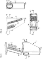
Fig. 1 eine Explosionsdarstellung, und -
Fig. 2 drei Ansichten des Funkenvorabscheiders gemäß Ausführungsbeispiel. - Der Funkenvorabscheider weist ein von Gehäusewänden begrenztes Gehäuse 1 mit einem Gasstromeingang 11 und einem dem Gasstromeingang 11 horizontal gegenüberliegend angeordneten Gasstromausgang 12 auf. In dem Gehäuse 1 zwischen dem Gasstromeingang 11 und dem Gasstromausgang 12 sind ein Strömungsteiler 2 und zwei Kulissen 3 angeordnet. Der Strömungsteiler 2 ist, bezogen auf einen von dem Gehäuse 1 definierten Strömungsquerschnitt, mittig angeordnet und überdeckt einen Teilquerschnitt dieses Strömungsquerschnitts.
- Der Strömungsteiler 2 ist dazu ausgebildet, den Gasstrom 4 in zwei horizontal nebeneinander strömende Teilströme 4a, 4b aufzuteilen und die Teilströme 4a, 4b seitlich zu verdrängen.
- Beiderseits des Strömungsteilers 2 und stromabwärts hinter dem Strömungsteiler 2 sind die beiden Kulissen 3 so angeordnet, dass sie den nicht von dem Strömungsteiler 2 überdeckten Restquerschnitt des Strömungsquerschnitts überdecken.
- Der Strömungsteiler 2 und die Kulissen 3 sind jeweils aus Blechstreifen aus Stahl oder Kupfer gefertigt, die sich von einer Oberseite aus auf eine Unterseite des Gehäuses zu erstrecken. Im Ausführungsbeispiel reichen der Strömungsteiler 2 und die Kulissen 3 jedoch nicht bis zur Unterseite des Gehäuses 1.
- Der Strömungsteiler 2 weist in der Ansicht von oben ein V-förmiges Strömungsprofil auf und die Kulissen 3 verlaufen in der Ansicht von oben parallel zu den Schenkeln des V-förmigen Strömungsprofils des Strömungsteilers 2. Der Strömungsteiler 2 und die Kulissen 3 sind gegenüber der Vertikalen so geneigt, dass auftreffende Partikel aufgrund der Schwerkraft von ihnen abfallen. Eine an der Unterseite des Gehäuses 1 angeordnete Partikelsammelöffnung 13 dient zur Entfernung abgeschiedener Partikel. Zu diesem Zweck ist die Partikelsammelöffnung 13 zur lösbaren Anbringung eines Partikelsammelbehälters ausgebildet.
-
- 1
- Gehäuse
- 11
- Gasstromeingang
- 12
- Gasstromausgang
- 13
- Partikelsammelöffnung
- 2
- Strömungsteiler
- 3
- Kulisse
- 4
- Gasstrom
- 4a, 4b
- Teilstrom
Claims (10)
- Funkenvorabscheider zur Abscheidung einer schweren Partikelfraktion aus einem Gasstrom (4), umfassend ein von Gehäusewänden begrenztes Gehäuse (1) mit einem Gasstromeingang (11) und einem dem Gasstromeingang (11) horizontal gegenüberliegend angeordneten Gasstromausgang (12), wobei• in dem Gehäuse (1) zwischen dem Gasstromeingang (11) und dem Gasstromausgang (12) ein Strömungsteiler (2) und zwei Kulissen (3) angeordnet sind,• der Strömungsteiler (2) bezogen auf einen von dem Gehäuse (1) definierten Strömungsquerschnitt mittig angeordnet ist, einen Teilquerschnitt dieses Strömungsquerschnitts überdeckt, in der Ansicht von oben ein V-förmiges Strömungsprofil aufweist und dadurch dazu ausgebildet ist, den Gasstrom (4) in zwei horizontal nebeneinander strömende Teilströme (4a, 4b) aufzuteilen und die Teilströme (4a, 4b) seitlich zu verdrängen,• und die beiden Kulissen (3) beiderseits des Strömungsteilers (2) und stromabwärts hinter dem Strömungsteiler (2) angeordnet sind, einen nicht von dem Strömungsteiler (2) überdeckten Restquerschnitt des Strömungsquerschnitts überdecken, in der Ansicht von oben parallel zu den Schenkeln des V-förmigen Strömungsprofils des Strömungsteilers (2) verlaufen und dadurch in dem von einer Kulisse und der angrenzenden Gehäusewand eingeschlossenen Winkel eine Funkenfalle gebildet ist.
- Funkenvorabscheider nach Anspruch 1, bei dem der Strömungsteiler (2) aus einem Blechstreifen gefertigt ist, der sich von einer Oberseite des Gehäuses (1) aus auf eine Unterseite des Gehäuses (1) zu erstreckt.
- Funkenvorabscheider nach Anspruch 1 oder 2, bei dem die Kulissen (3) aus je einem Blechstreifen gefertigt sind, die sich von einer Oberseite des Gehäuses (1) aus auf eine Unterseite des Gehäuses (1) zu erstrecken.
- Funkenvorabscheider nach einem der Ansprüche 1 bis 3, bei dem der Strömungsteiler (2) und die Kulissen (3) aus Kupfer gefertigt sind.
- Funkenvorabscheider nach einem der Ansprüche 1 bis 4, bei dem der Strömungsteiler (2) und die Kulissen (3) gegenüber der Vertikalen so geneigt sind, dass auftreffende Partikel aufgrund der Schwerkraft abfallen.
- Funkenvorabscheider nach einem der Ansprüche 1 bis 5, der eine an der Unterseite des Gehäuses (1) angeordnete Partikelsammelöffnung (13) zur Entfernung abgeschiedener Partikel aufweist.
- Funkenvorabscheider nach Anspruch 6, bei dem die Partikelsammelöffnung (13) zur lösbaren Anbringung eines Partikelsammelbehälters ausgebildet ist.
- Entstaubungsanlage zur Entstaubung von Rohgas, mit einem von Gehäusewänden begrenzten Anlagengehäuse, das eine Rohgas-Eintrittsöffnung und eine Reingas-Austrittsöffnung aufweist und das durch eine Filteranordnung in einen Rohgasraum und einen Reingasraum unterteilt ist, wobei die Entstaubungsanlage Funkenvorabscheider zur Abscheidung einer schweren Partikelfraktion aus dem Gas-Volumenstrom nach einem der Ansprüche 1 bis 7 umfasst.
- Entstaubungsanlage nach Anspruch 8, bei der der Gasstromausgang (12) des Funkenvorabscheiders unmittelbar mit der Rohgas-Eintrittsöffnung des Anlagengehäuses verbunden ist.
- Entstaubungsanlage nach Anspruch 9, bei der der Funkenvorabscheider an einem vom Anlagengehäuse entfernten Ort angeordnet und durch einen Lüftungskanal mit der Rohgas-Eintrittsöffnung des Anlagengehäuses verbunden ist.
Applications Claiming Priority (1)
| Application Number | Priority Date | Filing Date | Title |
|---|---|---|---|
| DE102019109146.2A DE102019109146A1 (de) | 2019-04-08 | 2019-04-08 | Funkenvorabscheider und Entstaubungsanlage |
Publications (2)
| Publication Number | Publication Date |
|---|---|
| EP3721968A1 EP3721968A1 (de) | 2020-10-14 |
| EP3721968B1 true EP3721968B1 (de) | 2021-12-22 |
Family
ID=70050002
Family Applications (1)
| Application Number | Title | Priority Date | Filing Date |
|---|---|---|---|
| EP20166105.5A Active EP3721968B1 (de) | 2019-04-08 | 2020-03-27 | Funkenvorabscheider und entstaubungsanlage |
Country Status (2)
| Country | Link |
|---|---|
| EP (1) | EP3721968B1 (de) |
| DE (1) | DE102019109146A1 (de) |
Families Citing this family (1)
| Publication number | Priority date | Publication date | Assignee | Title |
|---|---|---|---|---|
| DE102021111730A1 (de) | 2021-05-05 | 2022-11-10 | Lasco Heutechnik Gmbh | Brandschutzvorrichtung, Warmluftofen und Betriebsverfahren |
Family Cites Families (4)
| Publication number | Priority date | Publication date | Assignee | Title |
|---|---|---|---|---|
| US801435A (en) * | 1905-03-03 | 1905-10-10 | Oliver Lacy Anderson | Spark-arrester. |
| US3066464A (en) * | 1960-07-11 | 1962-12-04 | Briggs Wade | Diesel locomotive fire preventer |
| DE202010018247U1 (de) * | 2010-06-28 | 2014-12-16 | Esta Apparatebau Gmbh & Co. Kg | Partikelprallabscheider |
| AT513249B1 (de) * | 2012-12-20 | 2014-03-15 | Scheuch Gmbh | Filtervorrichtung |
-
2019
- 2019-04-08 DE DE102019109146.2A patent/DE102019109146A1/de not_active Withdrawn
-
2020
- 2020-03-27 EP EP20166105.5A patent/EP3721968B1/de active Active
Also Published As
| Publication number | Publication date |
|---|---|
| DE102019109146A1 (de) | 2020-10-08 |
| EP3721968A1 (de) | 2020-10-14 |
Similar Documents
| Publication | Publication Date | Title |
|---|---|---|
| EP2422865B1 (de) | Schweissrauchabsauganlage | |
| DE3249102T1 (de) | Kompaktstaubfilter | |
| WO2014079568A2 (de) | Dunstabzugshaube | |
| EP3721968B1 (de) | Funkenvorabscheider und entstaubungsanlage | |
| DE102013017868B4 (de) | Filtervorrichtung | |
| EP0014782A1 (de) | Entstaubungseinrichtung | |
| DE102015109999B4 (de) | Luftfilteranlage | |
| DE3624086A1 (de) | Zyklonabscheider | |
| EP3620721A1 (de) | Vorrichtung zur muldenabsaugung von auf einem kochfeld erzeugter abluft | |
| AT395834B (de) | Vorrichtung zum entstauben von gasen | |
| DE20215433U1 (de) | Vorrichtung zum Entfernen von Funken o.dgl. aus einem Gasstrom | |
| EP1637239A2 (de) | Vorrichtung zum Erfassen und Absaugen von gasförmigen Medien, insbesondere von Luft, mit Verunreinigungen in fester und/oder flüssiger Form | |
| DE1607536C3 (de) | Luftstromsichter | |
| EP3108951B1 (de) | Luftfilteranlage | |
| EP0059315A2 (de) | Vorrichtung zum Trennen von Schwebstoffen, wie Asche od. dgl. aus Rauchgasen | |
| DE475436C (de) | Entstaubungsvorrichtung fuer Rauchgase u. dgl. | |
| DE102005062525A1 (de) | Abscheidevorrichtung für Emissionen aus gehäuseartigen Umkleidungen von Maschinen, insbesondere Werkzeugmaschinen | |
| DE102011117830B4 (de) | Funkenlöschvorrichtung | |
| EP2399660A2 (de) | Partikelprallabscheider | |
| DE4340292A1 (de) | Schwebstoff-Filter mit Zentrifugal-Vorabscheidung | |
| EP3711840B1 (de) | Entstaubungsanlage | |
| DE19501990A1 (de) | Brennschneidetisch | |
| EP3108950B1 (de) | Materialabscheider | |
| DE102015118173A1 (de) | Absauganlage und Verfahren zur zumindest anteiligen Entfernung von Partikeln aus einem Gasgemisch | |
| DE7142343U (de) | Abscheider |
Legal Events
| Date | Code | Title | Description |
|---|---|---|---|
| PUAI | Public reference made under article 153(3) epc to a published international application that has entered the european phase |
Free format text: ORIGINAL CODE: 0009012 |
|
| STAA | Information on the status of an ep patent application or granted ep patent |
Free format text: STATUS: THE APPLICATION HAS BEEN PUBLISHED |
|
| AK | Designated contracting states |
Kind code of ref document: A1 Designated state(s): AL AT BE BG CH CY CZ DE DK EE ES FI FR GB GR HR HU IE IS IT LI LT LU LV MC MK MT NL NO PL PT RO RS SE SI SK SM TR |
|
| AX | Request for extension of the european patent |
Extension state: BA ME |
|
| STAA | Information on the status of an ep patent application or granted ep patent |
Free format text: STATUS: REQUEST FOR EXAMINATION WAS MADE |
|
| 17P | Request for examination filed |
Effective date: 20210409 |
|
| RBV | Designated contracting states (corrected) |
Designated state(s): AL AT BE BG CH CY CZ DE DK EE ES FI FR GB GR HR HU IE IS IT LI LT LU LV MC MK MT NL NO PL PT RO RS SE SI SK SM TR |
|
| GRAP | Despatch of communication of intention to grant a patent |
Free format text: ORIGINAL CODE: EPIDOSNIGR1 |
|
| STAA | Information on the status of an ep patent application or granted ep patent |
Free format text: STATUS: GRANT OF PATENT IS INTENDED |
|
| INTG | Intention to grant announced |
Effective date: 20210727 |
|
| GRAS | Grant fee paid |
Free format text: ORIGINAL CODE: EPIDOSNIGR3 |
|
| GRAA | (expected) grant |
Free format text: ORIGINAL CODE: 0009210 |
|
| STAA | Information on the status of an ep patent application or granted ep patent |
Free format text: STATUS: THE PATENT HAS BEEN GRANTED |
|
| RAP3 | Party data changed (applicant data changed or rights of an application transferred) |
Owner name: NOVUS AIR GMBH |
|
| AK | Designated contracting states |
Kind code of ref document: B1 Designated state(s): AL AT BE BG CH CY CZ DE DK EE ES FI FR GB GR HR HU IE IS IT LI LT LU LV MC MK MT NL NO PL PT RO RS SE SI SK SM TR |
|
| REG | Reference to a national code |
Ref country code: GB Ref legal event code: FG4D Free format text: NOT ENGLISH |
|
| REG | Reference to a national code |
Ref country code: CH Ref legal event code: EP |
|
| REG | Reference to a national code |
Ref country code: DE Ref legal event code: R096 Ref document number: 502020000462 Country of ref document: DE |
|
| REG | Reference to a national code |
Ref country code: AT Ref legal event code: REF Ref document number: 1456707 Country of ref document: AT Kind code of ref document: T Effective date: 20220115 |
|
| REG | Reference to a national code |
Ref country code: IE Ref legal event code: FG4D Free format text: LANGUAGE OF EP DOCUMENT: GERMAN |
|
| REG | Reference to a national code |
Ref country code: LT Ref legal event code: MG9D |
|
| PG25 | Lapsed in a contracting state [announced via postgrant information from national office to epo] |
Ref country code: RS Free format text: LAPSE BECAUSE OF FAILURE TO SUBMIT A TRANSLATION OF THE DESCRIPTION OR TO PAY THE FEE WITHIN THE PRESCRIBED TIME-LIMIT Effective date: 20211222 Ref country code: LT Free format text: LAPSE BECAUSE OF FAILURE TO SUBMIT A TRANSLATION OF THE DESCRIPTION OR TO PAY THE FEE WITHIN THE PRESCRIBED TIME-LIMIT Effective date: 20211222 Ref country code: FI Free format text: LAPSE BECAUSE OF FAILURE TO SUBMIT A TRANSLATION OF THE DESCRIPTION OR TO PAY THE FEE WITHIN THE PRESCRIBED TIME-LIMIT Effective date: 20211222 Ref country code: BG Free format text: LAPSE BECAUSE OF FAILURE TO SUBMIT A TRANSLATION OF THE DESCRIPTION OR TO PAY THE FEE WITHIN THE PRESCRIBED TIME-LIMIT Effective date: 20220322 |
|
| REG | Reference to a national code |
Ref country code: NL Ref legal event code: MP Effective date: 20211222 |
|
| PG25 | Lapsed in a contracting state [announced via postgrant information from national office to epo] |
Ref country code: SE Free format text: LAPSE BECAUSE OF FAILURE TO SUBMIT A TRANSLATION OF THE DESCRIPTION OR TO PAY THE FEE WITHIN THE PRESCRIBED TIME-LIMIT Effective date: 20211222 Ref country code: NO Free format text: LAPSE BECAUSE OF FAILURE TO SUBMIT A TRANSLATION OF THE DESCRIPTION OR TO PAY THE FEE WITHIN THE PRESCRIBED TIME-LIMIT Effective date: 20220322 Ref country code: LV Free format text: LAPSE BECAUSE OF FAILURE TO SUBMIT A TRANSLATION OF THE DESCRIPTION OR TO PAY THE FEE WITHIN THE PRESCRIBED TIME-LIMIT Effective date: 20211222 Ref country code: HR Free format text: LAPSE BECAUSE OF FAILURE TO SUBMIT A TRANSLATION OF THE DESCRIPTION OR TO PAY THE FEE WITHIN THE PRESCRIBED TIME-LIMIT Effective date: 20211222 Ref country code: GR Free format text: LAPSE BECAUSE OF FAILURE TO SUBMIT A TRANSLATION OF THE DESCRIPTION OR TO PAY THE FEE WITHIN THE PRESCRIBED TIME-LIMIT Effective date: 20220323 |
|
| PG25 | Lapsed in a contracting state [announced via postgrant information from national office to epo] |
Ref country code: NL Free format text: LAPSE BECAUSE OF FAILURE TO SUBMIT A TRANSLATION OF THE DESCRIPTION OR TO PAY THE FEE WITHIN THE PRESCRIBED TIME-LIMIT Effective date: 20211222 |
|
| PG25 | Lapsed in a contracting state [announced via postgrant information from national office to epo] |
Ref country code: SM Free format text: LAPSE BECAUSE OF FAILURE TO SUBMIT A TRANSLATION OF THE DESCRIPTION OR TO PAY THE FEE WITHIN THE PRESCRIBED TIME-LIMIT Effective date: 20211222 Ref country code: SK Free format text: LAPSE BECAUSE OF FAILURE TO SUBMIT A TRANSLATION OF THE DESCRIPTION OR TO PAY THE FEE WITHIN THE PRESCRIBED TIME-LIMIT Effective date: 20211222 Ref country code: RO Free format text: LAPSE BECAUSE OF FAILURE TO SUBMIT A TRANSLATION OF THE DESCRIPTION OR TO PAY THE FEE WITHIN THE PRESCRIBED TIME-LIMIT Effective date: 20211222 Ref country code: PT Free format text: LAPSE BECAUSE OF FAILURE TO SUBMIT A TRANSLATION OF THE DESCRIPTION OR TO PAY THE FEE WITHIN THE PRESCRIBED TIME-LIMIT Effective date: 20220422 Ref country code: ES Free format text: LAPSE BECAUSE OF FAILURE TO SUBMIT A TRANSLATION OF THE DESCRIPTION OR TO PAY THE FEE WITHIN THE PRESCRIBED TIME-LIMIT Effective date: 20211222 Ref country code: EE Free format text: LAPSE BECAUSE OF FAILURE TO SUBMIT A TRANSLATION OF THE DESCRIPTION OR TO PAY THE FEE WITHIN THE PRESCRIBED TIME-LIMIT Effective date: 20211222 Ref country code: CZ Free format text: LAPSE BECAUSE OF FAILURE TO SUBMIT A TRANSLATION OF THE DESCRIPTION OR TO PAY THE FEE WITHIN THE PRESCRIBED TIME-LIMIT Effective date: 20211222 |
|
| PG25 | Lapsed in a contracting state [announced via postgrant information from national office to epo] |
Ref country code: PL Free format text: LAPSE BECAUSE OF FAILURE TO SUBMIT A TRANSLATION OF THE DESCRIPTION OR TO PAY THE FEE WITHIN THE PRESCRIBED TIME-LIMIT Effective date: 20211222 |
|
| REG | Reference to a national code |
Ref country code: DE Ref legal event code: R097 Ref document number: 502020000462 Country of ref document: DE |
|
| PG25 | Lapsed in a contracting state [announced via postgrant information from national office to epo] |
Ref country code: IS Free format text: LAPSE BECAUSE OF FAILURE TO SUBMIT A TRANSLATION OF THE DESCRIPTION OR TO PAY THE FEE WITHIN THE PRESCRIBED TIME-LIMIT Effective date: 20220422 |
|
| PLBE | No opposition filed within time limit |
Free format text: ORIGINAL CODE: 0009261 |
|
| STAA | Information on the status of an ep patent application or granted ep patent |
Free format text: STATUS: NO OPPOSITION FILED WITHIN TIME LIMIT |
|
| PG25 | Lapsed in a contracting state [announced via postgrant information from national office to epo] |
Ref country code: MC Free format text: LAPSE BECAUSE OF FAILURE TO SUBMIT A TRANSLATION OF THE DESCRIPTION OR TO PAY THE FEE WITHIN THE PRESCRIBED TIME-LIMIT Effective date: 20211222 Ref country code: DK Free format text: LAPSE BECAUSE OF FAILURE TO SUBMIT A TRANSLATION OF THE DESCRIPTION OR TO PAY THE FEE WITHIN THE PRESCRIBED TIME-LIMIT Effective date: 20211222 Ref country code: AL Free format text: LAPSE BECAUSE OF FAILURE TO SUBMIT A TRANSLATION OF THE DESCRIPTION OR TO PAY THE FEE WITHIN THE PRESCRIBED TIME-LIMIT Effective date: 20211222 |
|
| 26N | No opposition filed |
Effective date: 20220923 |
|
| REG | Reference to a national code |
Ref country code: BE Ref legal event code: MM Effective date: 20220331 |
|
| PG25 | Lapsed in a contracting state [announced via postgrant information from national office to epo] |
Ref country code: LU Free format text: LAPSE BECAUSE OF NON-PAYMENT OF DUE FEES Effective date: 20220327 Ref country code: IE Free format text: LAPSE BECAUSE OF NON-PAYMENT OF DUE FEES Effective date: 20220327 Ref country code: FR Free format text: LAPSE BECAUSE OF NON-PAYMENT OF DUE FEES Effective date: 20220331 |
|
| PG25 | Lapsed in a contracting state [announced via postgrant information from national office to epo] |
Ref country code: SI Free format text: LAPSE BECAUSE OF FAILURE TO SUBMIT A TRANSLATION OF THE DESCRIPTION OR TO PAY THE FEE WITHIN THE PRESCRIBED TIME-LIMIT Effective date: 20211222 Ref country code: BE Free format text: LAPSE BECAUSE OF NON-PAYMENT OF DUE FEES Effective date: 20220331 |
|
| PG25 | Lapsed in a contracting state [announced via postgrant information from national office to epo] |
Ref country code: IT Free format text: LAPSE BECAUSE OF FAILURE TO SUBMIT A TRANSLATION OF THE DESCRIPTION OR TO PAY THE FEE WITHIN THE PRESCRIBED TIME-LIMIT Effective date: 20211222 |
|
| PGFP | Annual fee paid to national office [announced via postgrant information from national office to epo] |
Ref country code: DE Payment date: 20230328 Year of fee payment: 4 |
|
| REG | Reference to a national code |
Ref country code: CH Ref legal event code: PL |
|
| PG25 | Lapsed in a contracting state [announced via postgrant information from national office to epo] |
Ref country code: LI Free format text: LAPSE BECAUSE OF NON-PAYMENT OF DUE FEES Effective date: 20230331 Ref country code: CH Free format text: LAPSE BECAUSE OF NON-PAYMENT OF DUE FEES Effective date: 20230331 |
|
| PGFP | Annual fee paid to national office [announced via postgrant information from national office to epo] |
Ref country code: CH Payment date: 20231214 Year of fee payment: 4 |
|
| PGRI | Patent reinstated in contracting state [announced from national office to epo] |
Ref country code: LI Effective date: 20231214 Ref country code: CH Effective date: 20231214 |