EP3107747B1 - Structure d'abri, en particulier d'un plateau de charge, tel qu'une plateforme de camion, de remorque ou similaire, et abri intégrant une telle structure - Google Patents
Structure d'abri, en particulier d'un plateau de charge, tel qu'une plateforme de camion, de remorque ou similaire, et abri intégrant une telle structure Download PDFInfo
- Publication number
- EP3107747B1 EP3107747B1 EP15706905.5A EP15706905A EP3107747B1 EP 3107747 B1 EP3107747 B1 EP 3107747B1 EP 15706905 A EP15706905 A EP 15706905A EP 3107747 B1 EP3107747 B1 EP 3107747B1
- Authority
- EP
- European Patent Office
- Prior art keywords
- arch
- hoop
- uprights
- sliding
- shelter
- Prior art date
- Legal status (The legal status is an assumption and is not a legal conclusion. Google has not performed a legal analysis and makes no representation as to the accuracy of the status listed.)
- Active
Links
Images





Classifications
-
- B—PERFORMING OPERATIONS; TRANSPORTING
- B60—VEHICLES IN GENERAL
- B60J—WINDOWS, WINDSCREENS, NON-FIXED ROOFS, DOORS, OR SIMILAR DEVICES FOR VEHICLES; REMOVABLE EXTERNAL PROTECTIVE COVERINGS SPECIALLY ADAPTED FOR VEHICLES
- B60J5/00—Doors
- B60J5/04—Doors arranged at the vehicle sides
- B60J5/06—Doors arranged at the vehicle sides slidable; foldable
- B60J5/062—Doors arranged at the vehicle sides slidable; foldable for utility vehicles or public transport
- B60J5/065—Doors arranged at the vehicle sides slidable; foldable for utility vehicles or public transport with non-rigid elements, e.g. side curtains
-
- B—PERFORMING OPERATIONS; TRANSPORTING
- B60—VEHICLES IN GENERAL
- B60J—WINDOWS, WINDSCREENS, NON-FIXED ROOFS, DOORS, OR SIMILAR DEVICES FOR VEHICLES; REMOVABLE EXTERNAL PROTECTIVE COVERINGS SPECIALLY ADAPTED FOR VEHICLES
- B60J7/00—Non-fixed roofs; Roofs with movable panels, e.g. rotary sunroofs
- B60J7/02—Non-fixed roofs; Roofs with movable panels, e.g. rotary sunroofs of sliding type, e.g. comprising guide shoes
- B60J7/06—Non-fixed roofs; Roofs with movable panels, e.g. rotary sunroofs of sliding type, e.g. comprising guide shoes with non-rigid element or elements
-
- B—PERFORMING OPERATIONS; TRANSPORTING
- B60—VEHICLES IN GENERAL
- B60J—WINDOWS, WINDSCREENS, NON-FIXED ROOFS, DOORS, OR SIMILAR DEVICES FOR VEHICLES; REMOVABLE EXTERNAL PROTECTIVE COVERINGS SPECIALLY ADAPTED FOR VEHICLES
- B60J7/00—Non-fixed roofs; Roofs with movable panels, e.g. rotary sunroofs
- B60J7/02—Non-fixed roofs; Roofs with movable panels, e.g. rotary sunroofs of sliding type, e.g. comprising guide shoes
-
- B—PERFORMING OPERATIONS; TRANSPORTING
- B60—VEHICLES IN GENERAL
- B60J—WINDOWS, WINDSCREENS, NON-FIXED ROOFS, DOORS, OR SIMILAR DEVICES FOR VEHICLES; REMOVABLE EXTERNAL PROTECTIVE COVERINGS SPECIALLY ADAPTED FOR VEHICLES
- B60J7/00—Non-fixed roofs; Roofs with movable panels, e.g. rotary sunroofs
- B60J7/02—Non-fixed roofs; Roofs with movable panels, e.g. rotary sunroofs of sliding type, e.g. comprising guide shoes
- B60J7/06—Non-fixed roofs; Roofs with movable panels, e.g. rotary sunroofs of sliding type, e.g. comprising guide shoes with non-rigid element or elements
- B60J7/061—Non-fixed roofs; Roofs with movable panels, e.g. rotary sunroofs of sliding type, e.g. comprising guide shoes with non-rigid element or elements sliding and folding
- B60J7/064—Non-fixed roofs; Roofs with movable panels, e.g. rotary sunroofs of sliding type, e.g. comprising guide shoes with non-rigid element or elements sliding and folding using folding arms sliding in longitudinal tracks for supporting the soft roof
- B60J7/065—Non-fixed roofs; Roofs with movable panels, e.g. rotary sunroofs of sliding type, e.g. comprising guide shoes with non-rigid element or elements sliding and folding using folding arms sliding in longitudinal tracks for supporting the soft roof for utility vehicles
Definitions
- the present invention relates to a shelter structure, in particular a load plate, such as a platform truck, trailer or the like, and a shelter incorporating such a structure.
- Such a shelter structure is described in the patent FR-2891782 .
- Such a structure has the advantage of loading, from the top or one side of the tray, a container or a conventional cargo.
- the arches which are connected to the arches by a connection pivotally about an axis substantially parallel to the longitudinal axis of the crossbar of the arch, extend partially above the arches.
- the tops of the arches and arches extend substantially in the same plane to form a substantially flat roof.
- the portion of the arches projecting from the hoops in the folded position of the shelter structure constitutes a loss of height loading volume for the shelter structure. Indeed, it is necessary to lower the height of the arches to be able to respect the road gauge in the folded position of the structure.
- An object of the present invention is therefore to provide a shelter structure of the aforementioned type whose design optimizes the loading volume height of said structure without impairing the versatility of said structure.
- the articulated connection between arch and arch is, for at least one, preferably for each, arch in addition to a connection pivoting the arch about an axis transverse to the longitudinal axis of the amount of said arch, at least one sliding connection of the arch along an axis substantially parallel to the longitudinal axis of an amount of the arch, the tops of the arches and arches extend substantially in the same plane substantially parallel to the load plate, regardless of the deployed or folded position of the structure so that the loading volume height of said structure is optimal relative to the road gauge.
- each arch connected to a hoop by a pivotally and slidingly articulated connection, is, over at least part of its travel, from the deployed position to the folded position, in parallel with its pivotal displacement in the direction of an approximation of the hoop to which it is connected in an articulated manner, mounted movably sliding in the direction of a closer approximation of the lower end of the amounts of said hoop.
- each arch connected to a hoop by a hinged connection pivoting and sliding is, on at least part of its travel, from the folded position to the deployed position, in parallel with its pivotal displacement in the direction a spacing of the hoop to which it is connected in an articulated manner, mounted movably sliding in the direction of a closer approximation of the upper end of the amounts of said hoop.
- each arch connected to a hoop by a pivotally articulated connection and sliding is, in the deployed position, locked in sliding movement by means of locking means.
- the sliding locking means of the arch are of the automatic unlocking type and are unlockable by simply passing the arch from the deployed position to the folded position.
- each arch has the shape of an inverted U and the articulated connection between arch and hoop comprises hinged connection means arranged at the end of each branch of the U, between a branch of the U and an amount of 1 rollbar.
- the articulated connection pivoting and sliding between arch and arch comprises, at each amount of the arch, a light formed on the amount of the arch and a piece carried by the arch and movable to slide in said light.
- the light affects the shape of an inverted L with a so-called vertical portion substantially parallel to the amount of the arch, able to be traversed by the pin during the passage of the arch from one position to another, and a horizontal portion adapted to be occupied by the pin in the deployed position of the arch, and the sliding displacement locking means of said arch are formed at least partially by two of the edges of the horizontal portion of the light.
- each arch connected to a hoop by a pivotally articulated link and sliding, is, in addition to its pivotally articulated connection and sliding, coupled to each of the amounts of the arch by a rod whose ends are coupled respectively to the arch and the hoop member by a pivot connection axis substantially orthogonal to the longitudinal axis of the hoop amount.
- said structure comprises, for each arch connected to an arch by a pivotally articulated link and sliding, means restoring said arch in the deployed position.
- the return means comprise at least one spring disposed at one end of the link at the link of the connecting rod to the arch.
- the connecting means between the uprights of two adjacent hoops comprise, by pairs of uprights, a mast connected to said uprights facing said adjacent hoops by means of rods adapted to allow movement of the mast on one side or on the other side of the plane of displacement of the amounts opposite when the said structure is folded.
- the invention also relates to a shelter of a surface, in particular a load plate, such as a platform truck, trailer or the like, said shelter comprising a shelter structure and at least one element of cover tarpaulin type at least partially covering said shelter structure characterized in that said structure is of the aforementioned type.
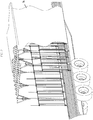
- the shelter structure 2 which is the subject of the invention, is in the form of an articulated framework capable of being covered with at least one tarpaulin-type flexible cover element 4 to form a shelter 1 horizontal surface, such as a truck platform, as shown in FIG. figure 1 .
- This structure 2 is secured to the load plate of the truck to form a protective enclosure of the load on said plate.
- This structure comprises a plurality of arches 5 capable of supporting said at least one covering element 4 tarpaulin type. These parallel arches 5 are each formed of uprights 6 opposite interconnected by a cross 7.
- the guide path 8 along which the amounts of the roll hoops is formed on the load plate 3 and is formed by the two edges longitudinals of said plateau.
- Each longitudinal edge consists of a rail open towards the outside of the plate in which the uprights of hoops can slide by means of rollers equipping their lower ends.
- the load plate 3 thus comprises two series of uprights 6 equipped with carriages, each series of uprights moving in a rail arranged along a longitudinal edge of the plate 3.
- the shelter structure 2 further comprises means 9 for connecting the uprights 6 opposite two adjacent arches 5. At least a portion of said connecting means 9 are movably mounted in a direction transverse to the plane of displacement of the uprights 6 during the passage of the structure 2 from one position to another.
- the connecting means 9 between the uprights 6 of two adjacent arches 5 comprise, by pair of uprights 6 opposite, a mast 91 connected to said uprights 6 facing said adjacent arches 5 by means of rods 92 able to allow the movement of the mast 9, on one side or the other of the plane of displacement of the uprights 6 opposite, during the folding of said structure 2.
- Said rods 92 can articulate the frame of the structure 2 so as to fold it.
- the masts 91 are not slidably mounted in the guide path, they can move laterally relative to the plate 3 thus making it possible to pass the shelter structure 2 in a folded position.
- the masts 91 are pushed back, inwards or outwards of the plate, so that the structure 2 adopts a form of accordion bellows.
- the figure 8 illustrates the detail of the connection between uprights 6 of poles and masts 91.
- two uprights 6 of arches are connected each by two links 92 to a mast 91 parallel to the uprights 6 of hoops.
- Amount 6, mast 91 and rods each form an articulated frame.
- the links 92 of a frame can be interconnected by panel elements to enhance the strength of the structure.
- Each mast 91 is equipped at each of its ends with a connecting piece of the mast 91 to the links 92.
- These links 92 are articulated on said connecting piece about an axis parallel to the axis of the mast.
- each other end of link is articulated to the carriage carrying the amount of 6 arch or a piece carried by said amount. Again, this articulation is performed using a pivot axis parallel to the axis of the amount.
- the masts 91 can move towards the inside or outside of the perimeter delimited by the uprights 6 of arches. It is advantageous that a direction of withdrawal of the masts 91 is preferred over the other.
- a stop movable between two positions, one locking preventing movement of the mast 91 in a direction perpendicular to the plane of displacement of the uprights 6, 1 other allowing movement of the mast 91 in said direction.
- This stop allows, during the folding of the structure, to define a preferred direction of withdrawal in which the operations to be performed are fast. Indeed, to fold said shelter structure, it is sufficient to exert a thrust on one end of said structure 2.
- This thrust slides the two sets of uprights 6 along their respective guide rail thus bringing the amounts of a series of each other and actuating the joints of the rods 92.
- the actuation of the rods 92 then causes a movement of the masts 91 perpendicular to the longitudinal axis of the plate to give the structure a form of accordion bellows.
- the presence of the stops ensures the operator performing the push that the masts all fold in the same direction.
- the stop position of the stop corresponds to a position in which said stop prevents movement of the mast towards the inside of the perimeter delimited by the uprights.
- the privileged sense of folding of the masts corresponds to a withdrawal towards the outside of the plateau.
- a simple push of the operator therefore causes a fold of the masts to the outside of the tray thus folding the shelter structure so that it completely releases the surface of the tray.
- This fallback mode corresponds to the conventional loading transport position. Indeed, the plate must be cleared to allow the loading of a cargo from the top or the side and said cargo must not hinder the deployment of the shelter structure once loading. Once folded outwards, the masts 91 do not protrude inside the plate 3, even during the unfolding operation.
- the stop In the unlocked position, the stop allows the folding of the masts 91 indifferently in one or the other direction, that is to say towards the inside or outside of the perimeter delimited by the plate.
- the abutment is generally made in the form of a pivoting or sliding piece extending outside the perimeter of the surface to be covered at the guide path in the deployed position of the shelter structure, said abutment being able to pivot along an axis parallel to the guide path or to slide along an axis perpendicular to the guide path, so as to move from an active position to an inactive position.
- the active position corresponds to the locking position in which only the folding of the masts to the outside is possible. Inactive position both directions are possible.
- the shelter structure 2 further comprises a plurality of arches 10.
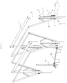
- Each arch 10 is connected to a hoop 5 by a hinged connection 11 to pass from a folded position, in which it extends in contact with said hoop 5 , at an extended position in which it forms an additional cross and vice versa.
- the link 11 articulated between arch 10 and arch 5 is, for at least one of the arches, in this case here for each of the arches 10, a pivotal connection of the arch 10 around an axis substantially parallel to the longitudinal axis of the crossbar 7 of said arch 5, and sliding of the arch 10 along an axis substantially parallel to the longitudinal axis of an amount 6 of the arch 5 .
- each arch 10 has the shape of an inverted U and the link 11 articulated between arch 10 and arch 5 comprises articulated connection means arranged at each branch of the U between the end of a branch of the U and an amount 6 of the arch 5.
- the link 11 articulated to pivoting and sliding between arch 10 and arch 5 comprises, at each amount of the arch 5, an oblong slot 12 formed on the upright 6 of the arch 5 and a pin 13 carried by the 10 and slidably movable in said lumen 12.
- the light 12 has the shape of an inverted L with a so-called vertical portion 121 substantially parallel to the upright 6 of the arch 5, able to be traversed by the pin 13 during the passage of the arch 10 from a position to a another, and a horizontal portion 122 adapted to be occupied by the pin 13 in the deployed position of the arch 10.
- the means 14 for locking in sliding displacement of said arch 10 are formed at least partially by two of the edges of the portion 122 Horizontal light 12.
- each arch 10 connected to a hoop 5 by a connection articulated to pivoting and sliding is in the deployed position, locked in sliding displacement.
- Each arch 10, connected to a hoop 5 by a pivotally and slidably articulated connection 11, is, in addition to its pivotally and slidably articulated connection 11, coupled to each of the uprights 6 of the hoop 5 by means of a link 16 whose ends are coupled respectively to the arch 10 and to the upright 6 of the arch 5 by a link 17 pivot axis orthogonal to the longitudinal axis of the upright 6 arch 5 and substantially parallel to the longitudinal axis of the crossbar said arch 5.
- Said structure 2 comprises, for each arch 10 connected to a hoop 5 by a connection articulated to pivoting and sliding, means 15 for returning said arch 10 in the deployed position.
- the return means 15 comprise here a spring disposed at one end of the rod 16 at the connection of the rod 16 to the arch 10.
- Each arch 10, connected to a bow 5 by a link 11 articulated to pivot and to sliding, is, over at least a portion of its travel, from the deployed position to the folded position, in parallel with its pivotal movement in the direction of a r engagement of the hoop 5 to which it is connected in an articulated manner, mounted slidably movable in the direction of a closer approximation of the lower end of the uprights 6 of said arch 5.
- each arch 10 connected to a hoop 5 by a linkage articulated pivotally and sliding, is, on at least a part of its stroke from the folded position to the extended position, in parallel with its pivotal displacement in the direction of a spacing of the hoop 5 to which it is articulately connected, mounted movably to the ulisme in the direction of a ruzement of the upper end of the uprights 6 of said arch 5.
- the pieces of the arch are positioned in the horizontal portion of the lights of the amounts so that in this position, any sliding movement of the arch along said amounts is prevented.
- the shelter structure 2 is generally covered with at least one cover element 4.
- the shelter structure 2 supports two flexible cover elements 4 of the tarpaulin type, one of said flexible cover elements 4 overlapping the lateral faces of the shelter structure, the other coming from cover the roof of the shelter structure.
- the lateral flexible cover element is preferably made in two parts, each of them covering a lateral face of the loading volume.
- each arch 10 is housed at least partially in a sheath of the tarpaulin-type flexible covering element overlapping the roof of the shelter structure to ensure guiding of the latter.
- Sleeves are thus formed in the roof covering element in order to insert the arches 10.
- these sleeves are obtained by sewing a yoke on the inner face of the sheet. This yoke delimiting with the tarpaulin a through conduit.
- This yoke is equipped with self-gripping Velcro (trademark) means to move from an open position, where the introduction of a crossbar of the arch inside the sheath is possible, to a closed position where transom and roof covering are interdependent.
- Substantially identical sleeves may also be placed on the lateral flexible cover element so as to secure it to the masts. In this case, each mast is inserted into a sheath formed on the lateral covering element.
- the operations necessary to fold the shelter structure inward of the perimeter delimited by the plate 3 will now be described.
- the folding of the masts 91 outward being preferred, it is necessary to unlock the stops in order to fold in the other direction.
- the stops are generally not accessible directly from outside the plate 3. They are indeed covered by the flexible side cover element.
- the sheet-like flexible cover element supported by the shelter structure is foldable outwardly, at its base, to form a flap held against the outer face of the sheet by means of appropriate retention, so as to facilitate access to the locking abutments.
- the tarpaulin is therefore raised at the guide path in the manner of a hem, in order to discover the stops.
- a system of straps arranged along the length of said flexible structure makes it possible to keep the tarpaulin in position while the operator operates the unlocking of the stops.
- the deployment of the structure is effected by simple reverse sliding movement of the amounts of arches along the guide path. As the top of the arches extends in the deployed position at the same level as the top of the arches in the folded position, the loading volume height of the shelter structure is optimal.
Landscapes
- Engineering & Computer Science (AREA)
- Mechanical Engineering (AREA)
- Tents Or Canopies (AREA)
Priority Applications (1)
| Application Number | Priority Date | Filing Date | Title |
|---|---|---|---|
| PL15706905T PL3107747T3 (pl) | 2014-02-19 | 2015-02-10 | Konstrukcja osłaniająca, zwłaszcza platformę ładunkową, taką jak platforma ciężarówki, przyczepy lub podobna, oraz osłona zawierająca taką konstrukcję |
Applications Claiming Priority (3)
| Application Number | Priority Date | Filing Date | Title |
|---|---|---|---|
| FR1451332A FR3017574B1 (fr) | 2014-02-19 | 2014-02-19 | Structure d'abri, en particulier d'un plateau de charge, tel qu'une plateforme de camion, de remorque ou similaire, et abri integrant une telle structure |
| US14/220,226 US9296284B2 (en) | 2014-02-19 | 2014-03-20 | Shelter structure, in particular for a load deck, such as a platform of a truck, a trailer, or the like, and a shelter incorporating such a structure |
| PCT/FR2015/050314 WO2015124843A1 (fr) | 2014-02-19 | 2015-02-10 | Structure d'abri, en particulier d'un plateau de charge, tel qu'une plateforme de camion, de remorque ou similaire, et abri intégrant une telle structure |
Publications (2)
| Publication Number | Publication Date |
|---|---|
| EP3107747A1 EP3107747A1 (fr) | 2016-12-28 |
| EP3107747B1 true EP3107747B1 (fr) | 2019-05-29 |
Family
ID=50780698
Family Applications (1)
| Application Number | Title | Priority Date | Filing Date |
|---|---|---|---|
| EP15706905.5A Active EP3107747B1 (fr) | 2014-02-19 | 2015-02-10 | Structure d'abri, en particulier d'un plateau de charge, tel qu'une plateforme de camion, de remorque ou similaire, et abri intégrant une telle structure |
Country Status (8)
| Country | Link |
|---|---|
| US (1) | US9296284B2 (pl) |
| EP (1) | EP3107747B1 (pl) |
| CA (1) | CA2937301C (pl) |
| DK (1) | DK3107747T3 (pl) |
| ES (1) | ES2743546T3 (pl) |
| FR (1) | FR3017574B1 (pl) |
| PL (1) | PL3107747T3 (pl) |
| WO (1) | WO2015124843A1 (pl) |
Families Citing this family (8)
| Publication number | Priority date | Publication date | Assignee | Title |
|---|---|---|---|---|
| CA2829500C (en) * | 2012-10-12 | 2019-02-12 | Magna International Inc. | Sliding | folding soft top assembly for suv |
| US10518823B1 (en) * | 2016-01-06 | 2019-12-31 | Cakeboxx Technologies, Llc | Two piece shipping container as covered flatbed trailer |
| DE202016101823U1 (de) * | 2016-04-06 | 2016-05-23 | European Trailer Systems Gmbh | Planenaufbau |
| DE202017104214U1 (de) * | 2017-07-14 | 2017-08-11 | European Trailer Systems Gmbh | Spannmittelhalter zum Einsatz in einen Planenaufbau sowie Planenaufbau |
| CN109533043B (zh) * | 2018-12-13 | 2020-06-19 | 重庆军通汽车有限责任公司 | 发烟车车厢 |
| CN114940316B (zh) * | 2021-02-07 | 2026-01-13 | 南通中集特种运输设备制造有限公司 | 篷布及集装箱组件 |
| FR3129109B1 (fr) * | 2021-11-12 | 2023-10-06 | S A Libner | Paroi pour la fermeture ou le cloisonnement d’espace et carrosserie de véhicule comprenant une telle paroi |
| CN115783338B (zh) * | 2022-12-16 | 2025-11-21 | 烟台市北海海洋工程技术有限公司 | 一种车载折叠甲板系统 |
Family Cites Families (19)
| Publication number | Priority date | Publication date | Assignee | Title |
|---|---|---|---|---|
| GB885082A (en) * | 1956-12-28 | 1961-12-20 | John Smith & Co London Ltd | Improvements in or relating to lorry tilt or cover frame structures |
| US3064667A (en) * | 1960-04-06 | 1962-11-20 | Frank J Marino | Portable loading canopy |
| US3140116A (en) * | 1962-01-26 | 1964-07-07 | Warren R Langdon | Side-loading vehicle |
| US4305415A (en) * | 1980-07-16 | 1981-12-15 | Joseph Galli | Motor vehicle housing |
| US4392682A (en) * | 1981-08-04 | 1983-07-12 | Norkus Jr Kasper | Expansible and retractable vehicle body |
| US5005896A (en) * | 1990-01-22 | 1991-04-09 | Li Cheng Chia | Retractable truck canopy frame |
| US5167246A (en) * | 1990-05-21 | 1992-12-01 | Magline, Inc. | Rapidly erectable and strikeable shelter frame system and methods of erecting and striking such systems |
| US5524953A (en) * | 1994-06-03 | 1996-06-11 | Shaer; Jack E. | Contractable vehicle bed cover assembly with extendable closure |
| US5839462A (en) * | 1997-05-19 | 1998-11-24 | Randall; Paul G. | Extensible and retractable canopy structure for vehicles and the like |
| JP3940976B2 (ja) * | 1997-06-05 | 2007-07-04 | 任昭 岩崎 | 収納テントにおける密閉機構 |
| US6905161B2 (en) * | 1998-09-01 | 2005-06-14 | Edscha Lkw-Schiebeverdecke Gmbh | Sliding-bow folding up |
| US6616211B2 (en) * | 2001-10-09 | 2003-09-09 | Cramaro Terpaulin Systems, Inc. | Tarpaulin tensioning arrangement |
| US6976433B1 (en) * | 2004-06-10 | 2005-12-20 | Dietmar Neumann | Slidable cover assembly for merchandise carrying vehicle platforms |
| FR2891782B1 (fr) * | 2005-10-12 | 2009-04-24 | Libner Sa Sa | Structure d'abri d'une surface, en particulier d'un plateau de charge |
| US7325855B2 (en) * | 2005-10-14 | 2008-02-05 | Aero Industries, Inc. | Uplift bow for a retractable tarping system |
| KR20100043209A (ko) * | 2007-07-19 | 2010-04-28 | 팅산랑 | 다기능 차량 캐노피 |
| US8235447B2 (en) * | 2010-02-04 | 2012-08-07 | Roll-Tite Corp. | Tensioning and lock device |
| CA2733761A1 (en) * | 2010-03-11 | 2011-09-11 | First Class Services, Inc. | Combination trailer |
| CA2810147C (en) * | 2012-03-21 | 2019-11-05 | Everest Damsi | Convertible tarp system |
-
2014
- 2014-02-19 FR FR1451332A patent/FR3017574B1/fr not_active Expired - Fee Related
- 2014-03-20 US US14/220,226 patent/US9296284B2/en active Active
-
2015
- 2015-02-10 CA CA2937301A patent/CA2937301C/fr active Active
- 2015-02-10 PL PL15706905T patent/PL3107747T3/pl unknown
- 2015-02-10 DK DK15706905.5T patent/DK3107747T3/da active
- 2015-02-10 EP EP15706905.5A patent/EP3107747B1/fr active Active
- 2015-02-10 WO PCT/FR2015/050314 patent/WO2015124843A1/fr not_active Ceased
- 2015-02-10 ES ES15706905T patent/ES2743546T3/es active Active
Non-Patent Citations (1)
| Title |
|---|
| None * |
Also Published As
| Publication number | Publication date |
|---|---|
| FR3017574B1 (fr) | 2017-08-11 |
| DK3107747T3 (da) | 2019-09-09 |
| CA2937301C (fr) | 2022-02-01 |
| PL3107747T3 (pl) | 2019-12-31 |
| US9296284B2 (en) | 2016-03-29 |
| WO2015124843A1 (fr) | 2015-08-27 |
| CA2937301A1 (fr) | 2015-08-27 |
| EP3107747A1 (fr) | 2016-12-28 |
| FR3017574A1 (fr) | 2015-08-21 |
| ES2743546T3 (es) | 2020-02-19 |
| US20150231952A1 (en) | 2015-08-20 |
Similar Documents
| Publication | Publication Date | Title |
|---|---|---|
| CA2937301C (fr) | Structure d'abri, en particulier d'un plateau de charge, tel qu'une plateforme de camion, de remorque ou similaire, et abri integrant une telle structure | |
| EP1215107B1 (fr) | Véhicule automobile à benne extensible | |
| EP0778169A1 (fr) | Dipositif pour le bâchage de véhicules poids lourd | |
| FR2707236A1 (fr) | Agencement d'un capot arrière ou analogue sur un cadre de carrosserie d'un véhicule. | |
| FR3014788A1 (fr) | Coffre a bagages avec plancher reglable pour vehicule | |
| EP1666365B1 (fr) | Conteneur du type à embase en forme de palette et à deux surfaces support | |
| EP2450017B1 (fr) | Procédé de montage de lit | |
| FR2598897A1 (fr) | Bagage transformable en chariot | |
| EP1775160B1 (fr) | Structure d'abri d'une surface, en particulier d'un plateau de charge | |
| FR3013272A1 (fr) | Abri roulant d'un nouveau type | |
| FR2920715A1 (fr) | Vehicule de type betailliere avec barrieres deployables pour la canalisation du betail | |
| EP3286064B1 (fr) | Châssis pliant de poussette pour enfant, et poussette correspondante | |
| EP3760482B1 (fr) | Plateau de chargement optimise pour porte-voitures et remorque ou semi-remorque comportant un tel plateau | |
| EP1765624B1 (fr) | Ouvrant de vehicule automobile, et vehicule pourvu d'un tel ouvrant | |
| WO2021148732A1 (fr) | Abri repliable de type gazebo | |
| EP1693276B1 (fr) | Poussette pour enfant à châssis pliant, comprenant un repose-pieds articulé | |
| FR3010682A1 (fr) | Poussette pliable adaptable au transport des nouveau-nes | |
| EP0741052A1 (fr) | Véhicule utilitaire comportant un bâti de couverture avec un rancher mobile | |
| FR2610574A1 (fr) | Dispositif d'ouverture et de fermeture d'elements de toits coulissants en vue de leur bachage | |
| EP1690715A1 (fr) | Véhicule convertible ayant une configuration pick-up | |
| FR2576556A1 (fr) | Perfectionnements aux vehicules munis de portes coulissantes a plusieurs vantaux adjacents | |
| EP4049870A1 (fr) | Benne équipée d'un dispositif de bâchage | |
| FR2891235A1 (fr) | Construction legere pour un capot de recouvrement d'un espace arriere de rangement d'un vehicule transformable | |
| FR2757831A1 (fr) | Palette de manutention d'objets longitudinaux | |
| FR2902724A1 (fr) | Agencement d'une tablette dans un caisson, notamment pour un vehicule automobile |
Legal Events
| Date | Code | Title | Description |
|---|---|---|---|
| PUAI | Public reference made under article 153(3) epc to a published international application that has entered the european phase |
Free format text: ORIGINAL CODE: 0009012 |
|
| STAA | Information on the status of an ep patent application or granted ep patent |
Free format text: STATUS: REQUEST FOR EXAMINATION WAS MADE |
|
| 17P | Request for examination filed |
Effective date: 20160825 |
|
| AK | Designated contracting states |
Kind code of ref document: A1 Designated state(s): AL AT BE BG CH CY CZ DE DK EE ES FI FR GB GR HR HU IE IS IT LI LT LU LV MC MK MT NL NO PL PT RO RS SE SI SK SM TR |
|
| AX | Request for extension of the european patent |
Extension state: BA ME |
|
| DAX | Request for extension of the european patent (deleted) | ||
| STAA | Information on the status of an ep patent application or granted ep patent |
Free format text: STATUS: EXAMINATION IS IN PROGRESS |
|
| 17Q | First examination report despatched |
Effective date: 20180516 |
|
| GRAP | Despatch of communication of intention to grant a patent |
Free format text: ORIGINAL CODE: EPIDOSNIGR1 |
|
| STAA | Information on the status of an ep patent application or granted ep patent |
Free format text: STATUS: GRANT OF PATENT IS INTENDED |
|
| INTG | Intention to grant announced |
Effective date: 20181221 |
|
| GRAS | Grant fee paid |
Free format text: ORIGINAL CODE: EPIDOSNIGR3 |
|
| GRAA | (expected) grant |
Free format text: ORIGINAL CODE: 0009210 |
|
| STAA | Information on the status of an ep patent application or granted ep patent |
Free format text: STATUS: THE PATENT HAS BEEN GRANTED |
|
| AK | Designated contracting states |
Kind code of ref document: B1 Designated state(s): AL AT BE BG CH CY CZ DE DK EE ES FI FR GB GR HR HU IE IS IT LI LT LU LV MC MK MT NL NO PL PT RO RS SE SI SK SM TR |
|
| REG | Reference to a national code |
Ref country code: GB Ref legal event code: FG4D Free format text: NOT ENGLISH |
|
| REG | Reference to a national code |
Ref country code: CH Ref legal event code: EP |
|
| REG | Reference to a national code |
Ref country code: AT Ref legal event code: REF Ref document number: 1138055 Country of ref document: AT Kind code of ref document: T Effective date: 20190615 |
|
| REG | Reference to a national code |
Ref country code: DE Ref legal event code: R096 Ref document number: 602015031093 Country of ref document: DE |
|
| REG | Reference to a national code |
Ref country code: IE Ref legal event code: FG4D Free format text: LANGUAGE OF EP DOCUMENT: FRENCH |
|
| REG | Reference to a national code |
Ref country code: DK Ref legal event code: T3 Effective date: 20190905 |
|
| REG | Reference to a national code |
Ref country code: NL Ref legal event code: MP Effective date: 20190529 |
|
| REG | Reference to a national code |
Ref country code: LT Ref legal event code: MG4D |
|
| PG25 | Lapsed in a contracting state [announced via postgrant information from national office to epo] |
Ref country code: SE Free format text: LAPSE BECAUSE OF FAILURE TO SUBMIT A TRANSLATION OF THE DESCRIPTION OR TO PAY THE FEE WITHIN THE PRESCRIBED TIME-LIMIT Effective date: 20190529 Ref country code: PT Free format text: LAPSE BECAUSE OF FAILURE TO SUBMIT A TRANSLATION OF THE DESCRIPTION OR TO PAY THE FEE WITHIN THE PRESCRIBED TIME-LIMIT Effective date: 20190930 Ref country code: HR Free format text: LAPSE BECAUSE OF FAILURE TO SUBMIT A TRANSLATION OF THE DESCRIPTION OR TO PAY THE FEE WITHIN THE PRESCRIBED TIME-LIMIT Effective date: 20190529 Ref country code: AL Free format text: LAPSE BECAUSE OF FAILURE TO SUBMIT A TRANSLATION OF THE DESCRIPTION OR TO PAY THE FEE WITHIN THE PRESCRIBED TIME-LIMIT Effective date: 20190529 Ref country code: NO Free format text: LAPSE BECAUSE OF FAILURE TO SUBMIT A TRANSLATION OF THE DESCRIPTION OR TO PAY THE FEE WITHIN THE PRESCRIBED TIME-LIMIT Effective date: 20190829 Ref country code: FI Free format text: LAPSE BECAUSE OF FAILURE TO SUBMIT A TRANSLATION OF THE DESCRIPTION OR TO PAY THE FEE WITHIN THE PRESCRIBED TIME-LIMIT Effective date: 20190529 Ref country code: LT Free format text: LAPSE BECAUSE OF FAILURE TO SUBMIT A TRANSLATION OF THE DESCRIPTION OR TO PAY THE FEE WITHIN THE PRESCRIBED TIME-LIMIT Effective date: 20190529 |
|
| PG25 | Lapsed in a contracting state [announced via postgrant information from national office to epo] |
Ref country code: BG Free format text: LAPSE BECAUSE OF FAILURE TO SUBMIT A TRANSLATION OF THE DESCRIPTION OR TO PAY THE FEE WITHIN THE PRESCRIBED TIME-LIMIT Effective date: 20190829 Ref country code: RS Free format text: LAPSE BECAUSE OF FAILURE TO SUBMIT A TRANSLATION OF THE DESCRIPTION OR TO PAY THE FEE WITHIN THE PRESCRIBED TIME-LIMIT Effective date: 20190529 Ref country code: GR Free format text: LAPSE BECAUSE OF FAILURE TO SUBMIT A TRANSLATION OF THE DESCRIPTION OR TO PAY THE FEE WITHIN THE PRESCRIBED TIME-LIMIT Effective date: 20190830 Ref country code: LV Free format text: LAPSE BECAUSE OF FAILURE TO SUBMIT A TRANSLATION OF THE DESCRIPTION OR TO PAY THE FEE WITHIN THE PRESCRIBED TIME-LIMIT Effective date: 20190529 |
|
| PG25 | Lapsed in a contracting state [announced via postgrant information from national office to epo] |
Ref country code: EE Free format text: LAPSE BECAUSE OF FAILURE TO SUBMIT A TRANSLATION OF THE DESCRIPTION OR TO PAY THE FEE WITHIN THE PRESCRIBED TIME-LIMIT Effective date: 20190529 Ref country code: NL Free format text: LAPSE BECAUSE OF FAILURE TO SUBMIT A TRANSLATION OF THE DESCRIPTION OR TO PAY THE FEE WITHIN THE PRESCRIBED TIME-LIMIT Effective date: 20190529 Ref country code: CZ Free format text: LAPSE BECAUSE OF FAILURE TO SUBMIT A TRANSLATION OF THE DESCRIPTION OR TO PAY THE FEE WITHIN THE PRESCRIBED TIME-LIMIT Effective date: 20190529 Ref country code: RO Free format text: LAPSE BECAUSE OF FAILURE TO SUBMIT A TRANSLATION OF THE DESCRIPTION OR TO PAY THE FEE WITHIN THE PRESCRIBED TIME-LIMIT Effective date: 20190529 Ref country code: SK Free format text: LAPSE BECAUSE OF FAILURE TO SUBMIT A TRANSLATION OF THE DESCRIPTION OR TO PAY THE FEE WITHIN THE PRESCRIBED TIME-LIMIT Effective date: 20190529 |
|
| REG | Reference to a national code |
Ref country code: ES Ref legal event code: FG2A Ref document number: 2743546 Country of ref document: ES Kind code of ref document: T3 Effective date: 20200219 |
|
| PG25 | Lapsed in a contracting state [announced via postgrant information from national office to epo] |
Ref country code: SM Free format text: LAPSE BECAUSE OF FAILURE TO SUBMIT A TRANSLATION OF THE DESCRIPTION OR TO PAY THE FEE WITHIN THE PRESCRIBED TIME-LIMIT Effective date: 20190529 |
|
| REG | Reference to a national code |
Ref country code: DE Ref legal event code: R097 Ref document number: 602015031093 Country of ref document: DE |
|
| PLBE | No opposition filed within time limit |
Free format text: ORIGINAL CODE: 0009261 |
|
| STAA | Information on the status of an ep patent application or granted ep patent |
Free format text: STATUS: NO OPPOSITION FILED WITHIN TIME LIMIT |
|
| 26N | No opposition filed |
Effective date: 20200303 |
|
| REG | Reference to a national code |
Ref country code: AT Ref legal event code: UEP Ref document number: 1138055 Country of ref document: AT Kind code of ref document: T Effective date: 20190529 |
|
| PG25 | Lapsed in a contracting state [announced via postgrant information from national office to epo] |
Ref country code: SI Free format text: LAPSE BECAUSE OF FAILURE TO SUBMIT A TRANSLATION OF THE DESCRIPTION OR TO PAY THE FEE WITHIN THE PRESCRIBED TIME-LIMIT Effective date: 20190529 |
|
| PG25 | Lapsed in a contracting state [announced via postgrant information from national office to epo] |
Ref country code: MC Free format text: LAPSE BECAUSE OF FAILURE TO SUBMIT A TRANSLATION OF THE DESCRIPTION OR TO PAY THE FEE WITHIN THE PRESCRIBED TIME-LIMIT Effective date: 20190529 |
|
| PG25 | Lapsed in a contracting state [announced via postgrant information from national office to epo] |
Ref country code: IE Free format text: LAPSE BECAUSE OF NON-PAYMENT OF DUE FEES Effective date: 20200210 |
|
| PG25 | Lapsed in a contracting state [announced via postgrant information from national office to epo] |
Ref country code: MT Free format text: LAPSE BECAUSE OF FAILURE TO SUBMIT A TRANSLATION OF THE DESCRIPTION OR TO PAY THE FEE WITHIN THE PRESCRIBED TIME-LIMIT Effective date: 20190529 Ref country code: CY Free format text: LAPSE BECAUSE OF FAILURE TO SUBMIT A TRANSLATION OF THE DESCRIPTION OR TO PAY THE FEE WITHIN THE PRESCRIBED TIME-LIMIT Effective date: 20190529 |
|
| PG25 | Lapsed in a contracting state [announced via postgrant information from national office to epo] |
Ref country code: MK Free format text: LAPSE BECAUSE OF FAILURE TO SUBMIT A TRANSLATION OF THE DESCRIPTION OR TO PAY THE FEE WITHIN THE PRESCRIBED TIME-LIMIT Effective date: 20190529 Ref country code: IS Free format text: LAPSE BECAUSE OF FAILURE TO SUBMIT A TRANSLATION OF THE DESCRIPTION OR TO PAY THE FEE WITHIN THE PRESCRIBED TIME-LIMIT Effective date: 20190929 |
|
| PGFP | Annual fee paid to national office [announced via postgrant information from national office to epo] |
Ref country code: ES Payment date: 20250331 Year of fee payment: 11 |
|
| REG | Reference to a national code |
Ref country code: CH Ref legal event code: U11 Free format text: ST27 STATUS EVENT CODE: U-0-0-U10-U11 (AS PROVIDED BY THE NATIONAL OFFICE) Effective date: 20260301 |
|
| PGFP | Annual fee paid to national office [announced via postgrant information from national office to epo] |
Ref country code: LU Payment date: 20260218 Year of fee payment: 12 |
|
| PGFP | Annual fee paid to national office [announced via postgrant information from national office to epo] |
Ref country code: GB Payment date: 20260219 Year of fee payment: 12 |
|
| PGFP | Annual fee paid to national office [announced via postgrant information from national office to epo] |
Ref country code: DE Payment date: 20260218 Year of fee payment: 12 Ref country code: DK Payment date: 20260220 Year of fee payment: 12 |
|
| PGFP | Annual fee paid to national office [announced via postgrant information from national office to epo] |
Ref country code: AT Payment date: 20260219 Year of fee payment: 12 |
|
| PGFP | Annual fee paid to national office [announced via postgrant information from national office to epo] |
Ref country code: BE Payment date: 20260218 Year of fee payment: 12 Ref country code: IT Payment date: 20260224 Year of fee payment: 12 |
|
| PGFP | Annual fee paid to national office [announced via postgrant information from national office to epo] |
Ref country code: FR Payment date: 20260218 Year of fee payment: 12 |
|
| PGFP | Annual fee paid to national office [announced via postgrant information from national office to epo] |
Ref country code: TR Payment date: 20260206 Year of fee payment: 12 |
|
| PGFP | Annual fee paid to national office [announced via postgrant information from national office to epo] |
Ref country code: CH Payment date: 20260301 Year of fee payment: 12 |
|
| PGFP | Annual fee paid to national office [announced via postgrant information from national office to epo] |
Ref country code: PL Payment date: 20260210 Year of fee payment: 12 |