EP3107693B1 - Handwerkzeugmaschine - Google Patents
Handwerkzeugmaschine Download PDFInfo
- Publication number
- EP3107693B1 EP3107693B1 EP15703606.2A EP15703606A EP3107693B1 EP 3107693 B1 EP3107693 B1 EP 3107693B1 EP 15703606 A EP15703606 A EP 15703606A EP 3107693 B1 EP3107693 B1 EP 3107693B1
- Authority
- EP
- European Patent Office
- Prior art keywords
- hand
- rings
- power tool
- held power
- piston
- Prior art date
- Legal status (The legal status is an assumption and is not a legal conclusion. Google has not performed a legal analysis and makes no representation as to the accuracy of the status listed.)
- Active
Links
Images
Classifications
-
- B—PERFORMING OPERATIONS; TRANSPORTING
- B25—HAND TOOLS; PORTABLE POWER-DRIVEN TOOLS; MANIPULATORS
- B25D—PERCUSSIVE TOOLS
- B25D17/00—Details of, or accessories for, portable power-driven percussive tools
- B25D17/06—Hammer pistons; Anvils ; Guide-sleeves for pistons
-
- B—PERFORMING OPERATIONS; TRANSPORTING
- B25—HAND TOOLS; PORTABLE POWER-DRIVEN TOOLS; MANIPULATORS
- B25D—PERCUSSIVE TOOLS
- B25D16/00—Portable percussive machines with superimposed rotation, the rotational movement of the output shaft of a motor being modified to generate axial impacts on the tool bit
-
- B—PERFORMING OPERATIONS; TRANSPORTING
- B25—HAND TOOLS; PORTABLE POWER-DRIVEN TOOLS; MANIPULATORS
- B25D—PERCUSSIVE TOOLS
- B25D2211/00—Details of portable percussive tools with electromotor or other motor drive
- B25D2211/06—Means for driving the impulse member
- B25D2211/068—Crank-actuated impulse-driving mechanisms
-
- B—PERFORMING OPERATIONS; TRANSPORTING
- B25—HAND TOOLS; PORTABLE POWER-DRIVEN TOOLS; MANIPULATORS
- B25D—PERCUSSIVE TOOLS
- B25D2216/00—Details of portable percussive machines with superimposed rotation, the rotational movement of the output shaft of a motor being modified to generate axial impacts on the tool bit
- B25D2216/0007—Details of percussion or rotation modes
- B25D2216/0023—Tools having a percussion-and-rotation mode
-
- B—PERFORMING OPERATIONS; TRANSPORTING
- B25—HAND TOOLS; PORTABLE POWER-DRIVEN TOOLS; MANIPULATORS
- B25D—PERCUSSIVE TOOLS
- B25D2217/00—Details of, or accessories for, portable power-driven percussive tools
- B25D2217/0011—Details of anvils, guide-sleeves or pistons
- B25D2217/0023—Pistons
-
- B—PERFORMING OPERATIONS; TRANSPORTING
- B25—HAND TOOLS; PORTABLE POWER-DRIVEN TOOLS; MANIPULATORS
- B25D—PERCUSSIVE TOOLS
- B25D2222/00—Materials of the tool or the workpiece
- B25D2222/21—Metals
- B25D2222/27—Brass
-
- B—PERFORMING OPERATIONS; TRANSPORTING
- B25—HAND TOOLS; PORTABLE POWER-DRIVEN TOOLS; MANIPULATORS
- B25D—PERCUSSIVE TOOLS
- B25D2222/00—Materials of the tool or the workpiece
- B25D2222/21—Metals
- B25D2222/31—Bronze
-
- B—PERFORMING OPERATIONS; TRANSPORTING
- B25—HAND TOOLS; PORTABLE POWER-DRIVEN TOOLS; MANIPULATORS
- B25D—PERCUSSIVE TOOLS
- B25D2222/00—Materials of the tool or the workpiece
- B25D2222/21—Metals
- B25D2222/33—Copper
-
- B—PERFORMING OPERATIONS; TRANSPORTING
- B25—HAND TOOLS; PORTABLE POWER-DRIVEN TOOLS; MANIPULATORS
- B25D—PERCUSSIVE TOOLS
- B25D2222/00—Materials of the tool or the workpiece
- B25D2222/54—Plastics
-
- B—PERFORMING OPERATIONS; TRANSPORTING
- B25—HAND TOOLS; PORTABLE POWER-DRIVEN TOOLS; MANIPULATORS
- B25D—PERCUSSIVE TOOLS
- B25D2250/00—General details of portable percussive tools; Components used in portable percussive tools
- B25D2250/345—Use of o-rings
Definitions
- the present invention relates to a hand tool with a pneumatic hammer mechanism, in particular a hammer drill, according to the preamble of claim 1.
- a generic hand tool is in the GB 2063141 A described.
- the striking mechanism has an excitation piston, which is moved back and forth periodically along an axis by an eccentric drive.
- the excitation piston is inserted into a guide tube coaxial with the axis.
- An inserted also in the guide tube racket is coupled by a trained between the exciter piston and the bat air spring to the movement of the exciter piston.
- the excitation piston and the guide tube are made of a plastic to improve the thermal efficiency of the impact mechanism.
- the use of the same material for the guide tube and the excitation piston ensures that they have the same coefficient of thermal expansion, which in turn allows the exciter piston to be manufactured with a small gap.
- the hand tool of the invention has a tool holder for receiving a tool on a working axis.
- a pneumatic percussion mechanism has an excitation piston which is forcedly moved by a motor periodically along the working axis and a racket which is coupled to the exciter piston via a pneumatic chamber.
- the excitation piston has a cylindrical body made of a polymer.
- One or more copper-containing rings span the body. The rings protrude in the radial direction with respect to the base body.
- the main body made of plastic is held by the rings at a distance from a guide tube.
- the copper-containing rings can reduce the coefficient of friction so much that an increased thermal loss and due to different thermal expansion coefficients over-compensated voltage.
- the excitation piston is preferably guided in a guide tube made of a polymer which thermally insulates the pneumatic chamber in the radial direction.
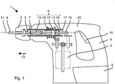
- Fig. 1 schematically shows a hammer drill 1 as an example of a chiseling hand tool .
- the hammer drill 1 has a tool holder 2, in which a shank end 3 of a tool, for example one of the drill 4, can be used.
- a primary drive of the hammer drill 1 is a motor 5, which drives a striking mechanism 6 and an output shaft 7 .
- a battery pack 8 or a power line supplies the motor 5 with power.
- a user can guide the hammer drill 1 by means of a handle 9 and be by means of a system switch 10 to the hammer drill 1 is in operation.
- the hammer drill 1 rotates the drill 4 continuously about a working axis 11 and can beat the drill 4 in the direction of impact 12 along the working axis 11 in a substrate.
- the percussion 6 is a pneumatic percussion 6.
- An exciter piston 13 and a racket 14 are movably guided in a guide tube 15 in the striking mechanism 6 along the working axis 11 .
- the excitation piston 13 is coupled via an eccentric 16 to the motor 5 and forced to a periodic, linear movement.
- a connecting rod 17 connects the eccentric 16 with the excitation piston 13.
- An air spring formed by a pneumatic chamber 18 between the excitation piston 13 and the racket 14 couples a movement of the racket 14 to the movement of the exciter piston 13 .
- the racket 14 can strike directly on a rear end of the drill 4 or indirectly transmit a portion of its pulse to the drill 4 via a substantially resting intermediate racket 19 .
- the striking mechanism 6 and preferably the further drive components are arranged within a machine housing 20 .
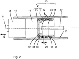
- the excitation piston 13 has a cup-shaped main body 21, which is oriented coaxially to the working axis 11 ( Fig. 2 ).
- the hollow body 21 has a substantially cylindrical shell 22 and is closed in the direction of impact 12 by a circular end face 23 .
- the main body 13 is made entirely of a polymer.
- One end of the connecting rod 17 is rotatably or pivotably mounted within the exciter piston 13 .
- the excitation piston 13 has one or more copper-containing rings 24, which surround the casing 22 of the main body 21 .
- the exciter piston 13 shown by way of example is provided with three identical rings 24 , which are arranged offset along the working axis 11 .
- the jacket 22 may be provided with annular grooves 25 , in which the rings 24 are embedded.
- the outer diameter 26 of the rings 24 is larger than the outer diameter 27 of the base body 21.
- the difference in outer diameter is between 0.2 mm to 1.0 mm.
- the rings 24 cover between 25% and 70% of the shell 22.
- its radial outer surface 28 is cylindrical, ie parallel to the working axis 11.
- the sliding surface formed by the rings 24 is large enough to the exciter piston 13 in the radial direction on the guide tube 15 support.
- the rings 24 do not form a continuous thermal bridge over the length of the excitation piston 13.
- a plurality of rings 24 are provided and these are separated from each other along the working axis 11 by a gap 29 .
- the copper-containing rings 24 are preferably made of bronze or brass.
- the exciter piston 13 is further provided with a sealing ring 30 made of an elastic material, for example rubber.
- the sealing ring 30 is inserted into a corresponding annular groove 31 near the end face 23 .
- the sealing ring 30 has the largest outer diameter 32 of the components of the excitation piston thirteenth
- the guide tube 15 is preferably made entirely of a polymer, or at least the inner surface 33 of the guide tube 15 is made of a polymer.
- the guide tube 15 made of polymer has a low thermal conductance and thus reduces thermal losses of the pneumatic chamber 18th
Landscapes
- Engineering & Computer Science (AREA)
- Mechanical Engineering (AREA)
- Percussive Tools And Related Accessories (AREA)
Description
- Die vorliegende Erfindung betrifft eine Handwerkzeugmaschine mit einem pneumatischen Schlagwerk, insbesondere einen Bohrhammer, gemäß dem Oberbegriff des Anspruchs 1. Eine gattungsgemäße Handwerkzeugmaschine ist in der
GB 2063141 A - Die erfindungsgemäße Handwerkzeugmaschine hat eine Werkzeugaufnahme zum Aufnehmen eines Werkzeugs auf einer Arbeitsachse. Ein pneumatisches Schlagwerk hat einen durch einen Motor periodisch längs der Arbeitsachse zwangsbewegten Erregerkolben und einen über eine pneumatische Kammer an den Erregerkolben angekoppelten Schläger. Der Erregerkolben hat einen zylindrischen Grundkörper aus einem Polymer. Ein oder mehrere kupferhaltige Ringe umspannen den Grundkörper. Die Ringe stehen gegenüber dem Grundkörper in radialer Richtung vor. Der Grundkörper aus Kunststoff wird durch die Ringe auf Abstand zu einem Führungsrohr gehalten. Die kupferhaltigen Ringe können den Reibwert soweit verringern, dass ein erhöhter thermischer Verlust und durch unterschiedliche thermische Ausdehnungskoeffizienten bedingte Spannung überkompensiert werden. Der Erregerkolben ist vorzugsweise in einem Führungsrohr aus einen Polymer geführt, welches die pneumatische Kammer in radialer Richtung thermisch isoliert.
- Die nachfolgende Beschreibung erläutert die Erfindung anhand von exemplarischen Ausführungsformen und Figuren. In den Figuren zeigen:
- Fig. 1
- einen Bohrhammer
- Fig. 2
- ein Schlagwerk
- Gleiche oder funktionsgleiche Elemente werden durch gleiche Bezugszeichen in den Figuren indiziert, soweit nicht anders angegeben.
-
Fig. 1 zeigt als Beispiel einer meißelnden Handwerkzeugmaschine schematisch einen Bohrhammer 1. Der Bohrhammer 1 hat eine Werkzeugaufnahme 2, in welche ein Schaftende 3 eines Werkzeug, z.B. eines des Bohrers 4, eingesetzt werden kann. Einen primären Antrieb des Bohrhammers 1 bildet ein Motor 5, welcher ein Schlagwerk 6 und eine Abtriebswelle 7 antreibt. Ein Batteriepaket 8 oder eine Netzleitung versorgt den Motor 5 mit Strom. Ein Anwender kann den Bohrhammer 1 mittels eines Handgriffs 9 führen und mittels eines Systemschalters 10 den Bohrhammer 1 in Betrieb nehmen. Im Betrieb dreht der Bohrhammer 1 den Bohrer 4 kontinuierlich um eine Arbeitsachse 11 und kann dabei den Bohrer 4 in Schlagrichtung 12 längs der Arbeitsachse 11 in einen Untergrund schlagen. - Das Schlagwerk 6 ist ein pneumatisches Schlagwerk 6. Ein Erregerkolben 13 und ein Schläger 14 sind in einem Führungsrohr 15 in dem Schlagwerk 6 längs der Arbeitsachse 11 beweglich geführt. Der Erregerkolben 13 ist über einen Exzenter 16 an den Motor 5 angekoppelt und zu einer periodischen, linearen Bewegung gezwungen. Ein Pleuel 17 verbindet den Exzenter 16 mit dem Erregerkolben 13. Eine Luftfeder gebildet durch eine pneumatische Kammer 18 zwischen dem Erregerkolben 13 und dem Schläger 14 koppelt eine Bewegung des Schlägers 14 an die Bewegung des Erregerkolbens 13 an. Der Schläger 14 kann direkt auf ein hinteres Ende des Bohrers 4 aufschlagen oder mittelbar über einen im Wesentlichen ruhenden Zwischenschläger 19 einen Teil seines Impuls auf den Bohrer 4 übertragen. Das Schlagwerk 6 und vorzugsweise die weiteren Antriebskomponenten sind innerhalb eines Maschinengehäuses 20 angeordnet.
- Der Erregerkolben 13 hat einen topfförmigen Grundkörper 21, welcher koaxial zu der Arbeitsachse 11 orientiert ist (
Fig. 2 ). Der hohle Grundkörper 21 hat einen im Wesentlichen zylindrischen Mantel 22 und ist in Schlagrichtung 12 durch eine kreisförmige Stirnfläche 23 abgeschlossen. Der Grundkörper 13 besteht vollständig aus einem Polymer. - Ein Ende des Pleuels 17 ist innerhalb des Erregerkolbens 13 drehbar oder schwenkbar gelagert.
- Der Erregerkolben 13 hat ein oder mehrere kupferhaltige Ringe 24, welche den Mantel 22 des Grundkörpers 21 umspannen. Der beispielhaft dargestellte Erregerkolben 13 ist mit drei gleichen Ringen 24 versehen, welche längs der Arbeitsachse 11 versetzt angeordnet sind. Der Mantel 22 kann mit ringförmigen Nuten 25 versehen sein, in welche die Ringe 24 eingelassen sind. Der Außendurchmesser 26 der Ringe 24 ist größer als der Außendurchmesser 27 des Grundkörpers 21. Vorzugsweise liegt die Differenz der Außendurchmesser zwischen 0,2 mm bis 1,0 mm.
- Die Ringe 24 bedecken zwischen 25 % und 70 % des Mantels 22. Vorzugsweise ist deren radiale Außenfläche 28 zylindrisch, d.h. parallel zu der Arbeitsachse 11. Die von den Ringen 24 gebildete Gleitfläche ist groß genug, um den Erregerkolben 13 in radialer Richtung an dem Führungsrohr 15 abzustützen. Andererseits bilden die Ringe 24 noch keine durchgehende Wärmebrücke über die Länge des Erregerkolbens 13. Vorzugsweise sind mehrere Ringe 24 vorgesehen und diese voneinander längs der Arbeitsachse 11 durch einen Spalt 29 getrennt sind.
- Die kupferhaltigen Ringe 24 sind vorzugsweise aus Bronze oder Messing.
- Der Erregerkolben 13 ist ferner mit einem Dichtring 30 aus einem elastischen Material, z.B. Kautschuk, versehen. Der Dichtring 30 ist in eine entsprechend ringförmige Nut 31 nahe der Stirnfläche 23 eingelegt. Der Dichtring 30 hat den größten Außendurchmesser 32 der Komponenten des Erregerkolbens 13.
- Das Führungsrohr 15 ist vorzugsweise vollständig aus einem Polymer, oder zumindest die Innenfläche 33 des Führungsrohrs 15 ist aus einem Polymer. Das Führungsrohr 15 aus Polymer hat einen geringen thermischen Leitwert und verringert somit thermische Verluste der pneumatischen Kammer 18.
Claims (5)
- Handwerkzeugmaschine mit
einer Werkzeugaufnahme (2) zum Aufnehmen eines Werkzeugs auf einer Arbeitsachse (11),
einem Motor (5),
einem pneumatischen Schlagwerk (6), das einen durch den Motor (5) periodisch längs der Arbeitsachse (11) zwangsbewegten Erregerkolben (13) und einen über eine pneumatische Kammer (18) an den Erregerkolben (13) angekoppelten Schläger (14) aufweist, wobei der Erregerkolben (13) einen zylindrischen Grundkörper (21) aus einem Polymer aufweist, dadurch gekennzeichnet, dass
ein oder mehrere kupferhaltige Ringe (24) den Grundkörper (21) umspannen und die Ringe (24) gegenüber dem Grundkörper (21) in radialer Richtung vorstehen. - Handwerkzeugmaschine nach Anspruch 1, dadurch gekennzeichnet, dass ein Außendurchmesser (26) der kupferhaltigen Ringe (24) zwischen 0,2 mm und 1,0 mm größer als ein Außendurchmesser (27) des Grundkörpers (21) ist.
- Handwerkzeugmaschine nach Anspruch 1 oder 2, dadurch gekennzeichnet, dass die Ringe (24) zwischen 25 % und 70 % eines Mantels (22) des Grundkörpers (21) bedecken.
- Handwerkzeugmaschine nach einem der vorhergehenden Ansprüche, dadurch gekennzeichnet, dass zwischen den Ringen (24) längs der Arbeitsachse (11) ein Spalt (29) vorgesehen ist.
- Handwerkzeugmaschine nach einem der vorhergehenden Ansprüche, dadurch gekennzeichnet, dass der Erregerkolben (13) in einem Führungsrohr (15) aus einen Polymer geführt ist.
Applications Claiming Priority (2)
| Application Number | Priority Date | Filing Date | Title |
|---|---|---|---|
| EP14156105.0A EP2910336A1 (de) | 2014-02-21 | 2014-02-21 | Handwerkzeugmaschine |
| PCT/EP2015/052813 WO2015124470A1 (de) | 2014-02-21 | 2015-02-11 | Handwerkzeugmaschine |
Publications (2)
| Publication Number | Publication Date |
|---|---|
| EP3107693A1 EP3107693A1 (de) | 2016-12-28 |
| EP3107693B1 true EP3107693B1 (de) | 2017-10-18 |
Family
ID=50150636
Family Applications (2)
| Application Number | Title | Priority Date | Filing Date |
|---|---|---|---|
| EP14156105.0A Withdrawn EP2910336A1 (de) | 2014-02-21 | 2014-02-21 | Handwerkzeugmaschine |
| EP15703606.2A Active EP3107693B1 (de) | 2014-02-21 | 2015-02-11 | Handwerkzeugmaschine |
Family Applications Before (1)
| Application Number | Title | Priority Date | Filing Date |
|---|---|---|---|
| EP14156105.0A Withdrawn EP2910336A1 (de) | 2014-02-21 | 2014-02-21 | Handwerkzeugmaschine |
Country Status (4)
| Country | Link |
|---|---|
| US (1) | US20170057072A1 (de) |
| EP (2) | EP2910336A1 (de) |
| CN (1) | CN105939821B (de) |
| WO (1) | WO2015124470A1 (de) |
Families Citing this family (2)
| Publication number | Priority date | Publication date | Assignee | Title |
|---|---|---|---|---|
| DE102018108280A1 (de) * | 2017-05-05 | 2018-11-08 | Fischerwerke Gmbh & Co. Kg | Setzgerät |
| EP3789161A1 (de) * | 2019-09-06 | 2021-03-10 | Hilti Aktiengesellschaft | Handwerkzeugmaschine |
Family Cites Families (19)
| Publication number | Priority date | Publication date | Assignee | Title |
|---|---|---|---|---|
| US3114423A (en) * | 1960-03-30 | 1963-12-17 | Skil Corp | Rotary-hammer device |
| DE2726214A1 (de) * | 1977-06-10 | 1978-12-21 | Hilti Ag | Bohrhammer mit pneumatisch angetriebenem schlagkolben |
| DE2945935A1 (de) | 1979-11-14 | 1981-05-27 | Robert Bosch Gmbh, 7000 Stuttgart | Handwerkzeugmaschine mit einem luftfederschlagwerk |
| DE3010479A1 (de) * | 1980-03-19 | 1981-10-08 | Robert Bosch Gmbh, 7000 Stuttgart | Werkzeugmaschine, insbesondere handwerkzeugmaschine mit einem luftfederschlagwerk |
| US4388776A (en) * | 1980-06-16 | 1983-06-21 | Tomy Corporation | Pneumatically operated toy employing a movable implement |
| US4554208A (en) * | 1983-12-27 | 1985-11-19 | General Motors Corporation | Metal bearing surface having an adherent score-resistant coating |
| SE8900947D0 (sv) * | 1989-03-16 | 1989-03-16 | Atlas Copco Ab | Slagverktyg |
| SE500864C2 (sv) * | 1989-10-28 | 1994-09-19 | Berema Atlas Copco Ab | Dämpanordning vid slagverk |
| US6395359B1 (en) * | 1997-08-13 | 2002-05-28 | The United States Of America As Represented By The Secretary Of The Navy | Power cylinder non-metallic liner seal assembly |
| US7032683B2 (en) * | 2001-09-17 | 2006-04-25 | Milwaukee Electric Tool Corporation | Rotary hammer |
| GB2423044A (en) * | 2005-02-10 | 2006-08-16 | Black & Decker Inc | Hammer with cam-actuated driven member |
| DE102005019710A1 (de) * | 2005-04-28 | 2006-11-09 | Robert Bosch Gmbh | Handwerkzeugmaschinenschlagwerkeinheit |
| FI119228B (fi) * | 2006-12-05 | 2008-09-15 | Sandvik Mining & Constr Oy | Rikotuslaitteen työkalun laakerointi |
| CN101444909B (zh) * | 2007-11-27 | 2013-03-27 | 希尔蒂股份公司 | 具有气动冲击装置的手持式工具机 |
| DE102009002474A1 (de) * | 2009-04-20 | 2010-10-21 | Hilti Aktiengesellschaft | Pneumatisches Schlagwerk und Handwerkzeugmaschine |
| DE102009026542A1 (de) * | 2009-05-28 | 2010-12-09 | Hilti Aktiengesellschaft | Werkzeugmaschine |
| CA2795798C (en) * | 2010-04-23 | 2019-08-27 | Smith International, Inc. | High pressure and high temperature ball seat |
| DE102010042809A1 (de) * | 2010-10-22 | 2012-04-26 | Hilti Aktiengesellschaft | Werkzeugmaschine |
| DE102011075765A1 (de) * | 2011-05-12 | 2012-11-15 | Hilti Aktiengesellschaft | Handwerkzeugmaschine |
-
2014
- 2014-02-21 EP EP14156105.0A patent/EP2910336A1/de not_active Withdrawn
-
2015
- 2015-02-11 US US15/120,269 patent/US20170057072A1/en not_active Abandoned
- 2015-02-11 WO PCT/EP2015/052813 patent/WO2015124470A1/de not_active Ceased
- 2015-02-11 CN CN201580006845.4A patent/CN105939821B/zh active Active
- 2015-02-11 EP EP15703606.2A patent/EP3107693B1/de active Active
Non-Patent Citations (1)
| Title |
|---|
| None * |
Also Published As
| Publication number | Publication date |
|---|---|
| EP2910336A1 (de) | 2015-08-26 |
| EP3107693A1 (de) | 2016-12-28 |
| CN105939821A (zh) | 2016-09-14 |
| WO2015124470A1 (de) | 2015-08-27 |
| CN105939821B (zh) | 2018-02-23 |
| US20170057072A1 (en) | 2017-03-02 |
Similar Documents
| Publication | Publication Date | Title |
|---|---|---|
| DE102015014559B4 (de) | Kraftwerkzeug | |
| EP2065139B1 (de) | Handwerkzeugmaschine mit pneumatischem Schlagwerk | |
| EP2243580A2 (de) | Pneumatisches Schlagwerk und Handwerkzeugmaschine mit einem solchen pneumatischen Schlagwerk | |
| EP3140081B1 (de) | Handwerkzeugmaschine | |
| DE2712863A1 (de) | Schlagwerkzeug zum abtragen von oberflaechen | |
| EP1340596B1 (de) | Pneumatisches Schlagwerk | |
| EP3233382B1 (de) | Handwerkzeugmaschine | |
| EP2910336A1 (de) | Handwerkzeugmaschine | |
| EP2842696B1 (de) | Handwerkzeugmaschine | |
| EP0679479B1 (de) | Handgerät zum Abtragen von Oberflächen | |
| EP1910039B1 (de) | Schlagwerk für eine wenigstens schlagend antreibbare Handwerkzeugmaschine | |
| EP3065914A1 (de) | Handwerkzeugmaschine | |
| EP3052273B1 (de) | Handwerkzeugmaschine | |
| DE112017002574T5 (de) | Schlagwerkzeug | |
| EP2822734B1 (de) | Handwerkzeugmaschinenvorrichtung | |
| DE810498C (de) | Elektrohammer | |
| EP3475031B1 (de) | Handwerkzeugmaschine | |
| EP3281749A1 (de) | Hilfsgriff für eine meisselnde werkzeugmaschine | |
| EP2163355A1 (de) | Elektrowerkzeug umfassend einen Taumeltrieb oder Kurbeltrieb mit reduzierter Masse | |
| EP2921265A1 (de) | Handwerkzeugmaschine | |
| DE735935C (de) | Kraftgetriebener Federhammer | |
| DE2551292C3 (de) | Druckluftbetriebene Tiefloch-Schlagbohrmaschine | |
| EP2813326A1 (de) | Werkzeugmaschine | |
| DE202017101853U1 (de) | Bodenbearbeitungsgerät | |
| DE202004017883U1 (de) | Buchse zur Aufnahme eines Werkzeugs |
Legal Events
| Date | Code | Title | Description |
|---|---|---|---|
| PUAI | Public reference made under article 153(3) epc to a published international application that has entered the european phase |
Free format text: ORIGINAL CODE: 0009012 |
|
| 17P | Request for examination filed |
Effective date: 20160921 |
|
| AK | Designated contracting states |
Kind code of ref document: A1 Designated state(s): AL AT BE BG CH CY CZ DE DK EE ES FI FR GB GR HR HU IE IS IT LI LT LU LV MC MK MT NL NO PL PT RO RS SE SI SK SM TR |
|
| AX | Request for extension of the european patent |
Extension state: BA ME |
|
| DAX | Request for extension of the european patent (deleted) | ||
| GRAP | Despatch of communication of intention to grant a patent |
Free format text: ORIGINAL CODE: EPIDOSNIGR1 |
|
| INTG | Intention to grant announced |
Effective date: 20170609 |
|
| GRAS | Grant fee paid |
Free format text: ORIGINAL CODE: EPIDOSNIGR3 |
|
| GRAA | (expected) grant |
Free format text: ORIGINAL CODE: 0009210 |
|
| AK | Designated contracting states |
Kind code of ref document: B1 Designated state(s): AL AT BE BG CH CY CZ DE DK EE ES FI FR GB GR HR HU IE IS IT LI LT LU LV MC MK MT NL NO PL PT RO RS SE SI SK SM TR |
|
| REG | Reference to a national code |
Ref country code: GB Ref legal event code: FG4D Free format text: NOT ENGLISH |
|
| REG | Reference to a national code |
Ref country code: CH Ref legal event code: EP |
|
| REG | Reference to a national code |
Ref country code: AT Ref legal event code: REF Ref document number: 937534 Country of ref document: AT Kind code of ref document: T Effective date: 20171115 Ref country code: IE Ref legal event code: FG4D Free format text: LANGUAGE OF EP DOCUMENT: GERMAN |
|
| REG | Reference to a national code |
Ref country code: DE Ref legal event code: R096 Ref document number: 502015002147 Country of ref document: DE |
|
| REG | Reference to a national code |
Ref country code: NL Ref legal event code: MP Effective date: 20171018 |
|
| REG | Reference to a national code |
Ref country code: LT Ref legal event code: MG4D |
|
| PG25 | Lapsed in a contracting state [announced via postgrant information from national office to epo] |
Ref country code: NL Free format text: LAPSE BECAUSE OF FAILURE TO SUBMIT A TRANSLATION OF THE DESCRIPTION OR TO PAY THE FEE WITHIN THE PRESCRIBED TIME-LIMIT Effective date: 20171018 |
|
| PG25 | Lapsed in a contracting state [announced via postgrant information from national office to epo] |
Ref country code: NO Free format text: LAPSE BECAUSE OF FAILURE TO SUBMIT A TRANSLATION OF THE DESCRIPTION OR TO PAY THE FEE WITHIN THE PRESCRIBED TIME-LIMIT Effective date: 20180118 Ref country code: ES Free format text: LAPSE BECAUSE OF FAILURE TO SUBMIT A TRANSLATION OF THE DESCRIPTION OR TO PAY THE FEE WITHIN THE PRESCRIBED TIME-LIMIT Effective date: 20171018 Ref country code: FI Free format text: LAPSE BECAUSE OF FAILURE TO SUBMIT A TRANSLATION OF THE DESCRIPTION OR TO PAY THE FEE WITHIN THE PRESCRIBED TIME-LIMIT Effective date: 20171018 Ref country code: SE Free format text: LAPSE BECAUSE OF FAILURE TO SUBMIT A TRANSLATION OF THE DESCRIPTION OR TO PAY THE FEE WITHIN THE PRESCRIBED TIME-LIMIT Effective date: 20171018 Ref country code: LT Free format text: LAPSE BECAUSE OF FAILURE TO SUBMIT A TRANSLATION OF THE DESCRIPTION OR TO PAY THE FEE WITHIN THE PRESCRIBED TIME-LIMIT Effective date: 20171018 |
|
| PG25 | Lapsed in a contracting state [announced via postgrant information from national office to epo] |
Ref country code: HR Free format text: LAPSE BECAUSE OF FAILURE TO SUBMIT A TRANSLATION OF THE DESCRIPTION OR TO PAY THE FEE WITHIN THE PRESCRIBED TIME-LIMIT Effective date: 20171018 Ref country code: BG Free format text: LAPSE BECAUSE OF FAILURE TO SUBMIT A TRANSLATION OF THE DESCRIPTION OR TO PAY THE FEE WITHIN THE PRESCRIBED TIME-LIMIT Effective date: 20180118 Ref country code: IS Free format text: LAPSE BECAUSE OF FAILURE TO SUBMIT A TRANSLATION OF THE DESCRIPTION OR TO PAY THE FEE WITHIN THE PRESCRIBED TIME-LIMIT Effective date: 20180218 Ref country code: RS Free format text: LAPSE BECAUSE OF FAILURE TO SUBMIT A TRANSLATION OF THE DESCRIPTION OR TO PAY THE FEE WITHIN THE PRESCRIBED TIME-LIMIT Effective date: 20171018 Ref country code: LV Free format text: LAPSE BECAUSE OF FAILURE TO SUBMIT A TRANSLATION OF THE DESCRIPTION OR TO PAY THE FEE WITHIN THE PRESCRIBED TIME-LIMIT Effective date: 20171018 Ref country code: GR Free format text: LAPSE BECAUSE OF FAILURE TO SUBMIT A TRANSLATION OF THE DESCRIPTION OR TO PAY THE FEE WITHIN THE PRESCRIBED TIME-LIMIT Effective date: 20180119 |
|
| REG | Reference to a national code |
Ref country code: DE Ref legal event code: R097 Ref document number: 502015002147 Country of ref document: DE |
|
| PG25 | Lapsed in a contracting state [announced via postgrant information from national office to epo] |
Ref country code: EE Free format text: LAPSE BECAUSE OF FAILURE TO SUBMIT A TRANSLATION OF THE DESCRIPTION OR TO PAY THE FEE WITHIN THE PRESCRIBED TIME-LIMIT Effective date: 20171018 Ref country code: DK Free format text: LAPSE BECAUSE OF FAILURE TO SUBMIT A TRANSLATION OF THE DESCRIPTION OR TO PAY THE FEE WITHIN THE PRESCRIBED TIME-LIMIT Effective date: 20171018 Ref country code: SK Free format text: LAPSE BECAUSE OF FAILURE TO SUBMIT A TRANSLATION OF THE DESCRIPTION OR TO PAY THE FEE WITHIN THE PRESCRIBED TIME-LIMIT Effective date: 20171018 Ref country code: CZ Free format text: LAPSE BECAUSE OF FAILURE TO SUBMIT A TRANSLATION OF THE DESCRIPTION OR TO PAY THE FEE WITHIN THE PRESCRIBED TIME-LIMIT Effective date: 20171018 |
|
| PLBE | No opposition filed within time limit |
Free format text: ORIGINAL CODE: 0009261 |
|
| STAA | Information on the status of an ep patent application or granted ep patent |
Free format text: STATUS: NO OPPOSITION FILED WITHIN TIME LIMIT |
|
| PG25 | Lapsed in a contracting state [announced via postgrant information from national office to epo] |
Ref country code: SM Free format text: LAPSE BECAUSE OF FAILURE TO SUBMIT A TRANSLATION OF THE DESCRIPTION OR TO PAY THE FEE WITHIN THE PRESCRIBED TIME-LIMIT Effective date: 20171018 Ref country code: PL Free format text: LAPSE BECAUSE OF FAILURE TO SUBMIT A TRANSLATION OF THE DESCRIPTION OR TO PAY THE FEE WITHIN THE PRESCRIBED TIME-LIMIT Effective date: 20171018 Ref country code: IT Free format text: LAPSE BECAUSE OF FAILURE TO SUBMIT A TRANSLATION OF THE DESCRIPTION OR TO PAY THE FEE WITHIN THE PRESCRIBED TIME-LIMIT Effective date: 20171018 |
|
| REG | Reference to a national code |
Ref country code: CH Ref legal event code: PL |
|
| 26N | No opposition filed |
Effective date: 20180719 |
|
| PG25 | Lapsed in a contracting state [announced via postgrant information from national office to epo] |
Ref country code: MC Free format text: LAPSE BECAUSE OF FAILURE TO SUBMIT A TRANSLATION OF THE DESCRIPTION OR TO PAY THE FEE WITHIN THE PRESCRIBED TIME-LIMIT Effective date: 20171018 Ref country code: MT Free format text: LAPSE BECAUSE OF FAILURE TO SUBMIT A TRANSLATION OF THE DESCRIPTION OR TO PAY THE FEE WITHIN THE PRESCRIBED TIME-LIMIT Effective date: 20171018 |
|
| REG | Reference to a national code |
Ref country code: IE Ref legal event code: MM4A |
|
| REG | Reference to a national code |
Ref country code: BE Ref legal event code: MM Effective date: 20180228 |
|
| PG25 | Lapsed in a contracting state [announced via postgrant information from national office to epo] |
Ref country code: SI Free format text: LAPSE BECAUSE OF FAILURE TO SUBMIT A TRANSLATION OF THE DESCRIPTION OR TO PAY THE FEE WITHIN THE PRESCRIBED TIME-LIMIT Effective date: 20171018 Ref country code: LU Free format text: LAPSE BECAUSE OF NON-PAYMENT OF DUE FEES Effective date: 20180211 Ref country code: LI Free format text: LAPSE BECAUSE OF NON-PAYMENT OF DUE FEES Effective date: 20180228 Ref country code: CH Free format text: LAPSE BECAUSE OF NON-PAYMENT OF DUE FEES Effective date: 20180228 |
|
| REG | Reference to a national code |
Ref country code: FR Ref legal event code: ST Effective date: 20181031 |
|
| PG25 | Lapsed in a contracting state [announced via postgrant information from national office to epo] |
Ref country code: IE Free format text: LAPSE BECAUSE OF NON-PAYMENT OF DUE FEES Effective date: 20180211 |
|
| PG25 | Lapsed in a contracting state [announced via postgrant information from national office to epo] |
Ref country code: BE Free format text: LAPSE BECAUSE OF NON-PAYMENT OF DUE FEES Effective date: 20180228 Ref country code: FR Free format text: LAPSE BECAUSE OF NON-PAYMENT OF DUE FEES Effective date: 20180228 |
|
| GBPC | Gb: european patent ceased through non-payment of renewal fee |
Effective date: 20190211 |
|
| PG25 | Lapsed in a contracting state [announced via postgrant information from national office to epo] |
Ref country code: GB Free format text: LAPSE BECAUSE OF NON-PAYMENT OF DUE FEES Effective date: 20190211 |
|
| PG25 | Lapsed in a contracting state [announced via postgrant information from national office to epo] |
Ref country code: TR Free format text: LAPSE BECAUSE OF FAILURE TO SUBMIT A TRANSLATION OF THE DESCRIPTION OR TO PAY THE FEE WITHIN THE PRESCRIBED TIME-LIMIT Effective date: 20171018 |
|
| PG25 | Lapsed in a contracting state [announced via postgrant information from national office to epo] |
Ref country code: PT Free format text: LAPSE BECAUSE OF FAILURE TO SUBMIT A TRANSLATION OF THE DESCRIPTION OR TO PAY THE FEE WITHIN THE PRESCRIBED TIME-LIMIT Effective date: 20171018 |
|
| PG25 | Lapsed in a contracting state [announced via postgrant information from national office to epo] |
Ref country code: CY Free format text: LAPSE BECAUSE OF FAILURE TO SUBMIT A TRANSLATION OF THE DESCRIPTION OR TO PAY THE FEE WITHIN THE PRESCRIBED TIME-LIMIT Effective date: 20171018 Ref country code: MK Free format text: LAPSE BECAUSE OF NON-PAYMENT OF DUE FEES Effective date: 20171018 Ref country code: HU Free format text: LAPSE BECAUSE OF FAILURE TO SUBMIT A TRANSLATION OF THE DESCRIPTION OR TO PAY THE FEE WITHIN THE PRESCRIBED TIME-LIMIT; INVALID AB INITIO Effective date: 20150211 Ref country code: RO Free format text: LAPSE BECAUSE OF FAILURE TO SUBMIT A TRANSLATION OF THE DESCRIPTION OR TO PAY THE FEE WITHIN THE PRESCRIBED TIME-LIMIT Effective date: 20171018 |
|
| PG25 | Lapsed in a contracting state [announced via postgrant information from national office to epo] |
Ref country code: AL Free format text: LAPSE BECAUSE OF FAILURE TO SUBMIT A TRANSLATION OF THE DESCRIPTION OR TO PAY THE FEE WITHIN THE PRESCRIBED TIME-LIMIT Effective date: 20171018 |
|
| REG | Reference to a national code |
Ref country code: AT Ref legal event code: MM01 Ref document number: 937534 Country of ref document: AT Kind code of ref document: T Effective date: 20200211 |
|
| PG25 | Lapsed in a contracting state [announced via postgrant information from national office to epo] |
Ref country code: AT Free format text: LAPSE BECAUSE OF NON-PAYMENT OF DUE FEES Effective date: 20200211 |
|
| PGFP | Annual fee paid to national office [announced via postgrant information from national office to epo] |
Ref country code: DE Payment date: 20260218 Year of fee payment: 12 |