EP3106959B1 - Drohne, die perfektionierte mittel zur kompensation der verzerrung des trägheitsnavigationssystems in abhängigkeit von der temperatur umfasst - Google Patents
Drohne, die perfektionierte mittel zur kompensation der verzerrung des trägheitsnavigationssystems in abhängigkeit von der temperatur umfasst Download PDFInfo
- Publication number
- EP3106959B1 EP3106959B1 EP16173188.0A EP16173188A EP3106959B1 EP 3106959 B1 EP3106959 B1 EP 3106959B1 EP 16173188 A EP16173188 A EP 16173188A EP 3106959 B1 EP3106959 B1 EP 3106959B1
- Authority
- EP
- European Patent Office
- Prior art keywords
- imu
- temperature
- drone
- heating component
- bias
- Prior art date
- Legal status (The legal status is an assumption and is not a legal conclusion. Google has not performed a legal analysis and makes no representation as to the accuracy of the status listed.)
- Active
Links
Images


Classifications
-
- G—PHYSICS
- G01—MEASURING; TESTING
- G01P—MEASURING LINEAR OR ANGULAR SPEED, ACCELERATION, DECELERATION, OR SHOCK; INDICATING PRESENCE, ABSENCE, OR DIRECTION, OF MOVEMENT
- G01P21/00—Testing or calibrating of apparatus or devices covered by the preceding groups
-
- G—PHYSICS
- G05—CONTROLLING; REGULATING
- G05D—SYSTEMS FOR CONTROLLING OR REGULATING NON-ELECTRIC VARIABLES
- G05D23/00—Control of temperature
- G05D23/19—Control of temperature characterised by the use of electric means
- G05D23/20—Control of temperature characterised by the use of electric means with sensing elements having variation of electric or magnetic properties with change of temperature
-
- B—PERFORMING OPERATIONS; TRANSPORTING
- B64—AIRCRAFT; AVIATION; COSMONAUTICS
- B64U—UNMANNED AERIAL VEHICLES [UAV]; EQUIPMENT THEREFOR
- B64U10/00—Type of UAV
-
- B—PERFORMING OPERATIONS; TRANSPORTING
- B64—AIRCRAFT; AVIATION; COSMONAUTICS
- B64U—UNMANNED AERIAL VEHICLES [UAV]; EQUIPMENT THEREFOR
- B64U20/00—Constructional aspects of UAVs
- B64U20/80—Arrangement of on-board electronics, e.g. avionics systems or wiring
- B64U20/83—Electronic components structurally integrated with aircraft elements, e.g. circuit boards carrying loads
-
- G—PHYSICS
- G01—MEASURING; TESTING
- G01C—MEASURING DISTANCES, LEVELS OR BEARINGS; SURVEYING; NAVIGATION; GYROSCOPIC INSTRUMENTS; PHOTOGRAMMETRY OR VIDEOGRAMMETRY
- G01C19/00—Gyroscopes; Turn-sensitive devices using vibrating masses; Turn-sensitive devices without moving masses; Measuring angular rate using gyroscopic effects
-
- G—PHYSICS
- G01—MEASURING; TESTING
- G01C—MEASURING DISTANCES, LEVELS OR BEARINGS; SURVEYING; NAVIGATION; GYROSCOPIC INSTRUMENTS; PHOTOGRAMMETRY OR VIDEOGRAMMETRY
- G01C21/00—Navigation; Navigational instruments not provided for in groups G01C1/00 - G01C19/00
- G01C21/10—Navigation; Navigational instruments not provided for in groups G01C1/00 - G01C19/00 by using measurements of speed or acceleration
- G01C21/12—Navigation; Navigational instruments not provided for in groups G01C1/00 - G01C19/00 by using measurements of speed or acceleration executed aboard the object being navigated; Dead reckoning
- G01C21/16—Navigation; Navigational instruments not provided for in groups G01C1/00 - G01C19/00 by using measurements of speed or acceleration executed aboard the object being navigated; Dead reckoning by integrating acceleration or speed, i.e. inertial navigation
- G01C21/183—Compensation of inertial measurements, e.g. for temperature effects
-
- G—PHYSICS
- G01—MEASURING; TESTING
- G01C—MEASURING DISTANCES, LEVELS OR BEARINGS; SURVEYING; NAVIGATION; GYROSCOPIC INSTRUMENTS; PHOTOGRAMMETRY OR VIDEOGRAMMETRY
- G01C25/00—Manufacturing, calibrating, cleaning, or repairing instruments or devices referred to in the other groups of this subclass
- G01C25/005—Manufacturing, calibrating, cleaning, or repairing instruments or devices referred to in the other groups of this subclass initial alignment, calibration or starting-up of inertial devices
-
- G—PHYSICS
- G05—CONTROLLING; REGULATING
- G05D—SYSTEMS FOR CONTROLLING OR REGULATING NON-ELECTRIC VARIABLES
- G05D23/00—Control of temperature
- G05D23/19—Control of temperature characterised by the use of electric means
- G05D23/1919—Control of temperature characterised by the use of electric means characterised by the type of controller
Definitions
- the invention relates to motorized flying machines such as drones, in particular rotary-wing drones of the quadricopter type.
- the AR.Drone 2.0 or the Bebop Drone from Parrot SA, Paris, France are typical examples of such quadcopters. They are equipped with a series of sensors (accelerometers, 3-axis gyrometers, altimeters), a front camera capturing an image of the scene towards which the drone is directed and a vertical aiming camera capturing an image of the terrain overflown . They are provided with multiple rotors driven by respective motors controllable in a differentiated manner in order to pilot the drone in attitude and speed.
- the inertial measurement unit or IMU Inertial Measurement Unit
- IMU Inertial Measurement Unit
- the temperature of the IMU can vary significantly, typically between + 30 ° C and + 60 ° C during the same use. Indeed, at the start of use the temperature of the IMU is close to ambient temperature, but during use the heating of the components and in particular of the processor causes a rise in the temperature inside the body of the drone. . Conversely, starting the engines and a rapid flight cause a flow of cold air tending to lower this temperature, which can then rise to much higher values when the drone lands on the ground, etc.
- the error of the gyrometric signals (and, similarly, of the accelerometric signals) delivered by the IMU presents a drift (bias) both important (several degrees of angle per second) and variable with temperature.
- the temperature variations of the sensors are likely to cause a hysteresis effect on the drift of the latter, which makes the continuous correction of the bias imprecise.
- the IMU undergoes a calibration procedure in the factory, consisting in varying the ambient temperature in a controlled manner, in reading the internal temperature of the IMU (chip temperature, given by a sensor internal to the IMU), and to measure the corresponding bias.
- a bias / temperature characteristic generally a nonlinear characteristic that can be modeled by a polynomial.
- the descriptive parameters of this characteristic are kept in memory and will be used later to correct in real time the bias of the measurement delivered by the sensors, according to the temperature recorded at a given time.
- This procedure is applicable to a drone fitted with a chip temperature sensor internal to the IMU, such as that described for example in the article by L Petriccia et al., "Design, fabrication and test of an embedded lightweight kinematic autopilot (ELKA)", International Journal of Intelligent Unmanned Systems, Vol. 2, May 2014, pp. 140-150 .
- ELKA embedded lightweight kinematic autopilot
- the invention proposes a drone comprising, in itself known in particular from the aforementioned article by Petriccia et al., A main circuit board on which electronic components are mounted as well as an inertial unit, IMU, comprising gyrometric sensors for measuring the instantaneous rotation of the drone in an absolute coordinate system, and / or accelerometric sensors for measuring the acceleration of the drone in this coordinate system, the IMU including an internal temperature sensor delivering a chip temperature signal.
- a quadricopter type drone is shown, with a drone body 10 comprising in the lower part a chassis 12 secured to four link arms 14 radiating from the chassis. Each arm is equipped at its distal end with a propulsion unit 16 comprising a motor driving a propeller in rotation 18. In the lower part, the propulsion unit 16 is extended by a stirrup forming a foot 20 on which the drone can rest on the ground. 'stop.
- the drone body comprises a plate 22 intended to receive the main circuit board 24 carrying almost all of the electronic components of the drone, including the latter's inertial unit.
- the plate 22 is in the form of a one-piece element made of light metallic material and acts as a cooler to evacuate the excess calories from certain components which generate large amounts of heat such as the main processor, the radio chip, the motor switching MOSFETs, etc.
- the cooling effect is increased by the air flows resulting from the aerodynamic effects, and possibly by starting a fan, especially when the drone is not flying.
- the Figure 2 is an enlarged view of the main circuit board 24, where the inertial unit 26 is located.
- This inertial unit (IMU) is a component incorporating a three-axis gyrometer and a three-axis accelerometer.
- a heating component 28 capable of producing, in a controlled manner, thermal energy.
- This energy is intended to be supplied to the IMU 26, via a thermally conductive element 30, which is for example a metallic flat layer (copper layer) incorporated in the main circuit board and extending to both under IMU 26 and under heating component 28.
- This metallic flat layer acts as a thermal guide between the heating component 28 and the IMU 26 so as to allow transfer (symbolized by the arrows 32) to the IMU of the heat produced by the heating component.
- the IMU incorporates a sensor 34 delivering a signal for measuring its internal temperature (chip temperature of the IMU). As will be described in detail below, this signal ⁇ ° chip will be used to ensure thermal regulation by controlled activation of the heating component 28.
- the Figure 3 illustrates the heating component 28 and its control stage 36.
- the component 28 can be a simple resistor but, as illustrated, it is preferably constituted by a bipolar transistor associated with a bias stage 38 of the base of this transistor. The polarization is adjusted so as to operate the transistor 28 in resistive mode, the generation of heat occurring essentially at the level of the collector.
- the transistor is for example a PNP of power 2STN2550 from STMicroelectronics.
- the polarization divider 38 of the base of the transistor 28 is controlled "all or nothing" by a switching transistor 40, for example a N-channel MOSFET whose gate receives a digital signal TH-PWM, which is a binary signal of PWM type (pulse width modulation) whose duty cycle is between 0 and 100%. It is thus possible to control in a manner both very fine and very reactive the switching on of the transistor 28, and therefore the amount of heat given off by it, between a minimum and a maximum according to the duty cycle of the signal TH_PWM.
- a switching transistor 40 for example a N-channel MOSFET whose gate receives a digital signal TH-PWM, which is a binary signal of PWM type (pulse width modulation) whose duty cycle is between 0 and 100%.
- the metallic flat layer 30 forming a thermal guide of the main circuit board 24 is advantageously an electric ground plane GND_GYRO common to the IMU 26 and to the heating component 28, this mass GND_GYRO being connected to the common ground GND of the circuit card main by a strap 42.
- the Figure 4 illustrates the thermal regulation circuit for controlling the temperature of the IMU. It should be noted that, although these diagrams are presented in the form of block diagrams according to a standardized formalism, the implementation of the various functions is essentially software, this representation having only an illustrative character.
- This regulation circuit is based on a PI (proportional-integral) control, with a proportional loop 44 and a discrete integrating loop 46, 50-56.
- a PI regulator is sufficient because the model of temperature transfer can be approximated as being a first order linear system therefore easily controllable by a simple PID even if this model is unknown.
- This regulation operates on the basis of an error signal e corresponding to a difference between the observed temperature, namely the chip temperature ⁇ ° chip (temperature of the IMU 26, measured by the sensor 34) and a reference temperature ⁇ ° ref stored in 48.
- ⁇ ° ref 50 ° C, value higher than the asymptotic temperature and lower than the maximum temperature of the IMU indicated by the manufacturer's specifications.
- the system operates in discrete time, corresponding to digital sampling. We can then assimilate the integral to a sum of the signal over a time period determined by block 50, this sum being calculated by blocks 52 to 56.
- the blocks 58 and 60 combine the outputs of the proportional and integrating loops 44 and 46 and bring the resulting signal to a range of variation 0-100% (to allow control relative to the cyclic).
- the result is stored in a PWM register 62 and applied as an input (signal TH_PWM) to the piloting circuit 36 of the heating component 28. It will be noted that in the flight configurations the cooling of the card is done naturally by the plate 22, the ratio PWM signal cyclic then being at 0%.
- the controlled activation of the heating component 36 makes it possible to heat the IMU as necessary to reach and maintain a reference temperature closest to a constant value.
- the temperature rise is thus accelerated and a nominal temperature of the IMU 26 is quickly reached which will be close to a fairly stable asymptote, where the variations in bias will be minimized and will have little hysteresis effect.
- the heating component is used to heat the IMU during its factory calibration (or during a subsequent recalibration).
- the card is held in static position, without the plate 22 (whose presence would have the effect of slowing the rise in temperature), and the bias of the gyrometers and accelerometers are measured while the temperature increases.
- the IMU can for example be heated in 150 seconds from an initial temperature of + 30 ° C to a final temperature of + 65 ° C, a time much less than the 20 minutes envisaged by the aforementioned article by Niu et al.
- the bias observed is memorized for each temperature value (chip temperature delivered by the sensor 34), and the bias / temperature characteristic obtained is then modeled in the form of a polynomial, for example a polynomial of the third order, by implementing a conventional recursive polynomial regression technique, recursion avoiding having to memorize all the data.
- Dynamic calibration consists of placing the card on a mobile unit to perform predetermined rotations at constant speed along the three axes. During this dynamic calibration, the heating component can be deactivated. During the predetermined rotations, the signals delivered by the IMU sensors are picked up and a thermal correction is applied to them as a function of the chip temperature, this thermal correction being calculated from the polynomial values previously stored during the static calibration. .
- the temperature corrected data are for example used in a general algorithm of gradient descent type making it possible to calibrate the inertial data with respect to a theoretical rotation.
- the duration of this dynamic calibration is of the order of 45 seconds, a duration entirely compatible with factory production at a high rate.
- the method is the same as for the initial static calibration in the factory. Note that this recalibration can be done easily, without dismantling the drone (while the factory calibration is done on the card in isolation), with the drone in its environment, that it can be repeated as necessary, and that 'it only lasts a very limited time, around 2 to 3 minutes.
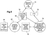
- the Figure 5 is a diagram explaining the different processes i) of calibration, ii) of thermal regulation and iii) of bias correction implemented according to the invention.
- the thermal regulation process 70 consists in heating the IMU by the heating component 28 via its piloting circuit 36 and the servo-control chain illustrated.
- Figure 4 Input variables are the reference temperature ⁇ ° ref stored in 72 and the chip temperature ⁇ ° chip of the IMU delivered in 74.
- the IMU calibration process 76 consists in calculating the thermal drifts of the IMU by finding the polynomial that best approaches the bias / temperature characteristic. This process can be carried out at the factory, or repeated by the user if he wishes to recalibrate the IMU later.
- the input / output data are the file 78 of the polynomial parameters, obtained by the factory calibration, as well as those of the last recalibration if necessary. These files also keep parameters corresponding to the IMU scale factor errors, which can possibly be used in addition (we can refer in this regard to the article by Niu et al. For more details).
- the IMU bias correction process 80 receives the raw IMU measurements delivered at 82, the internal temperature ⁇ ° chip of the IMU chip delivered at 74, and the data of the characteristic polynomials. bias / temperature stored in 78. The bias correction is made on the basis of the current temperature of the chip, and produces in 84 IMU corrected measurements of the temperature.
Landscapes
- Engineering & Computer Science (AREA)
- Remote Sensing (AREA)
- Radar, Positioning & Navigation (AREA)
- Physics & Mathematics (AREA)
- General Physics & Mathematics (AREA)
- Automation & Control Theory (AREA)
- Aviation & Aerospace Engineering (AREA)
- Mechanical Engineering (AREA)
- Microelectronics & Electronic Packaging (AREA)
- Manufacturing & Machinery (AREA)
- Gyroscopes (AREA)
- Navigation (AREA)
Claims (11)
- Drohne, aufweisend eine Haupt-Leiterplatte (24), auf der elektronische Komponenten montiert sind, sowie eine inertiale Messeinheit, IMU, (26), die Drehbewegungsmesssensoren zum Messen der kurzzeitigen Drehungen einer Drohne in einem absoluten Bezugssystem und/oder Beschleunigungssensoren zum Messen der Beschleunigungen der Drohne in diesem Bezugssystem umfasst, wobei die IMU (26) einen Innentemperatursensor (34) umfasst, der ein Chip-Temperatur-Signal (θ°chip) ausgibt,
dadurch gekennzeichnet, dass sie Folgendes umfasst:- eine Heizkomponente (28), die auf der Leiterplatte (24) in der Nähe der IMU (26) montiert ist,- einen thermischen Leiter (30), der in die Leiterplatte (24) eingearbeitet ist, wobei dieser thermische Leiter sich zwischen der Heizkomponente (28) und der IMU (26) so erstreckt, dass er einen Transfer (32) der von der Heizkomponente erzeugten Wärme ermöglicht; und- eine Wärmeregelungsschaltung (44-62), die am Eingang das Chip-Temperatur-Signal (θ°Chip) und ein vorher bestimmtes Soll-Temperatur-Signal (θ°Ref) empfängt und am Ausgang ein Signal zum Ansteuern (TH_PWM) der Heizkomponente ausgibt, um die Wärmezufuhr zu der IMU in Abhängigkeit von der Abweichung zwischen Chip-Temperatur und Soll-Temperatur zu steuern. - Drohne nach Anspruch 1, ferner umfassend:- einen Speicher (78), der Werte eines Polynoms abspeichert, die sich einer Verzerrungs-/Chip-Temperatur-Kennlinie der IMU annähern; und- eine Schaltung zur Korrektur thermischer Fehler (80), die imstande ist, auf die von den Drehbewegungsmess- und Beschleunigungssensoren ausgegebenen Rohsignale (82) Verzerrungskorrekturen in Abhängigkeit von der Chip-Temperatur anzuwenden, wobei diese Korrekturen auf den im Speicher abgespeicherten Polynomwerten basieren.
- Drohne nach Anspruch 1, wobei der thermische Leiter eine flächige Metallschicht (30) ist, die in die Leiterplatte (24) eingearbeitet ist und sich unter der IMU (26) und unter der Heizkomponente (28) erstreckt.
- Drohne nach Anspruch 3, wobei die flächige Metallschicht eine elektrische Erdungsebene (GND_GYRO) der IMU und der Heizkomponente ist, die mit der gemeinsamen Masse (GND) der Leiterplatte verbunden ist.
- Drohne nach Anspruch 1, wobei die Heizkomponente ein Bipolartransistor ist, der einer Stufe (38) der gesteuerten Polarisation der Basis dieses Transistors zugeordnet ist, in Abhängigkeit von dem Ansteuerungssignal (TH_PWM), das von der Wärmeregelungsschaltung ausgegeben wird.
- Drohne nach Anspruch 1, wobei das Ansteuerungssignal (TH_PWM), das von der Wärmeregelungsschaltung ausgegeben wird, ein PWM-Signal ist, dessen zyklisches Verhältnis in Abhängigkeit von der Abweichung zwischen der Chip-Temperatur und der Soll-Temperatur moduliert ist.
- Verfahren zum Kalibrieren der IMU (26) einer Drohne nach Anspruch 1, umfassend die folgenden Schritte:a) Ansteuern der Heizkomponente (28), um eine Chip-Temperatur-Rampe zu erzeugen, die sich progressiv von einer Anfangstemperatur zu einer Endtemperatur verändert;b) während dieser Temperatur-Rampe, Bestimmen der Verzerrungswerte der IMU (26) für eine Mehrzahl von Chip-Temperatur- Werten und Erstellen einer Verzerrungs-/Temperatur-Kennlinie;c) Ermitteln eines Polynoms, das sich möglichst nahe der in Schritt b) erhaltenen Kennlinie annähert; undd) Speichern der Werte des in Schritt c) ermittelten Polynoms als Verzerrungskorrekturwerte der IMU in Abhängigkeit von der Chip-Temperatur.
- Verfahren nach Anspruch 7, bei dem die Anfangstemperatur eine Umgebungstemperatur ist und die Endtemperatur eine Nennbetriebstemperatur der IMU ist.
- Verfahren nach Anspruch 7, bei dem die Dauer der Temperaturrampe in Schritt b), von der Anfangstemperatur zu der Endtemperatur, kleiner als 3 Minuten ist.
- Verfahren nach Anspruch 7, bei dem der Schritt b) in einer statischen Konfiguration der IMU ausgeführt wird, und dadurch dass ferner nach Schritt d) eine dynamische Kalibrierung der IMU vorgesehen ist, umfassend die Schritte:e) Anordnen der Leiterplatte auf einem Drehträger und Aufbringen von vorher bestimmten Drehungen auf die IMU; undf) während dieser vorher bestimmten Drehungen Bestimmen der von den Drehbewegungsmesssensoren der IMU ausgegebenen Rohsignale und Anwenden einer thermischen Korrektur in Abhängigkeit von der Chip-Temperatur auf diese Rohsignale, wobei diese Korrekturen auf den in Schritt d) gespeicherten Polynomwerten basieren.
- Verfahren nach Anspruch 10, bei dem die Heizkomponente während der Schritte e) und f) deaktiviert ist.
Applications Claiming Priority (1)
| Application Number | Priority Date | Filing Date | Title |
|---|---|---|---|
| FR1555455A FR3037672B1 (fr) | 2015-06-16 | 2015-06-16 | Drone comportant des moyens perfectionnes de compensation du biais de la centrale inertielle en fonction de la temperature |
Publications (2)
| Publication Number | Publication Date |
|---|---|
| EP3106959A1 EP3106959A1 (de) | 2016-12-21 |
| EP3106959B1 true EP3106959B1 (de) | 2020-03-25 |
Family
ID=54145830
Family Applications (1)
| Application Number | Title | Priority Date | Filing Date |
|---|---|---|---|
| EP16173188.0A Active EP3106959B1 (de) | 2015-06-16 | 2016-06-06 | Drohne, die perfektionierte mittel zur kompensation der verzerrung des trägheitsnavigationssystems in abhängigkeit von der temperatur umfasst |
Country Status (5)
| Country | Link |
|---|---|
| US (1) | US10191080B2 (de) |
| EP (1) | EP3106959B1 (de) |
| JP (1) | JP2017015697A (de) |
| CN (1) | CN106257371A (de) |
| FR (1) | FR3037672B1 (de) |
Families Citing this family (49)
| Publication number | Priority date | Publication date | Assignee | Title |
|---|---|---|---|---|
| EP3062142B1 (de) | 2015-02-26 | 2018-10-03 | Nokia Technologies OY | Vorrichtung für augennahe Anzeige |
| US10650552B2 (en) | 2016-12-29 | 2020-05-12 | Magic Leap, Inc. | Systems and methods for augmented reality |
| EP3343267B1 (de) | 2016-12-30 | 2024-01-24 | Magic Leap, Inc. | Polychromatische lichtauskopplungsvorrichtung, augennahe anzeige damit und verfahren zur polychromatischem lichtauskopplung |
| CN108513565B (zh) * | 2017-06-27 | 2021-11-23 | 深圳市大疆创新科技有限公司 | 无人机 |
| US10578870B2 (en) | 2017-07-26 | 2020-03-03 | Magic Leap, Inc. | Exit pupil expander |
| CN207060377U (zh) * | 2017-08-01 | 2018-03-02 | 广州极飞科技有限公司 | 无人机 |
| CN107562092B (zh) * | 2017-08-31 | 2020-11-10 | 上海航天控制技术研究所 | 一种可编程可受控的温控电路、方法和介质 |
| CN107807696B (zh) * | 2017-09-22 | 2021-02-02 | 上海卫星工程研究所 | 星上加热器精密温控方法 |
| CN110869278B (zh) | 2017-10-10 | 2023-08-08 | 盐城辉空科技有限公司 | 飞行体 |
| JP6578477B2 (ja) | 2017-10-10 | 2019-09-25 | 株式会社エアロネクスト | 回転翼機 |
| CN107977026B (zh) * | 2017-11-24 | 2021-04-06 | 深圳市科比特航空科技有限公司 | 基于陀螺仪传感器的温度控制装置及无人机 |
| KR102596429B1 (ko) | 2017-12-10 | 2023-10-30 | 매직 립, 인코포레이티드 | 광학 도파관들 상의 반사―방지 코팅들 |
| KR102761610B1 (ko) | 2017-12-20 | 2025-01-31 | 매직 립, 인코포레이티드 | 증강 현실 뷰잉 디바이스용 인서트 |
| DE112018006754T5 (de) | 2018-01-03 | 2020-09-24 | Aeronext Inc. | Fluggerät und flugverfahren dafür |
| CN112136152B (zh) | 2018-03-15 | 2025-02-07 | 奇跃公司 | 由观看设备的部件变形导致的图像校正 |
| US11040782B1 (en) | 2018-03-21 | 2021-06-22 | William Michael Johnson | Adjustable leveling drone platform |
| CN112236713B (zh) | 2018-05-30 | 2023-01-24 | 奇跃公司 | 紧凑的可变聚焦配置 |
| JP7319303B2 (ja) | 2018-05-31 | 2023-08-01 | マジック リープ, インコーポレイテッド | レーダ頭部姿勢位置特定 |
| CN112400157B (zh) | 2018-06-05 | 2024-07-09 | 奇跃公司 | 观看系统的基于单应性变换矩阵的温度校准 |
| WO2020010097A1 (en) | 2018-07-02 | 2020-01-09 | Magic Leap, Inc. | Pixel intensity modulation using modifying gain values |
| US11510027B2 (en) | 2018-07-03 | 2022-11-22 | Magic Leap, Inc. | Systems and methods for virtual and augmented reality |
| US11856479B2 (en) | 2018-07-03 | 2023-12-26 | Magic Leap, Inc. | Systems and methods for virtual and augmented reality along a route with markers |
| JP7374981B2 (ja) | 2018-07-10 | 2023-11-07 | マジック リープ, インコーポレイテッド | クロス命令セットアーキテクチャプロシージャ呼出のためのスレッドウィービング |
| US11624929B2 (en) | 2018-07-24 | 2023-04-11 | Magic Leap, Inc. | Viewing device with dust seal integration |
| CN119197613A (zh) * | 2018-07-24 | 2024-12-27 | 奇跃公司 | 移动检测设备的依赖于温度的校准 |
| WO2020028834A1 (en) | 2018-08-02 | 2020-02-06 | Magic Leap, Inc. | A viewing system with interpupillary distance compensation based on head motion |
| JP7438188B2 (ja) | 2018-08-03 | 2024-02-26 | マジック リープ, インコーポレイテッド | ユーザ相互作用システムにおけるトーテムの融合姿勢の非融合姿勢ベースのドリフト補正 |
| JP7487176B2 (ja) | 2018-08-22 | 2024-05-20 | マジック リープ, インコーポレイテッド | 患者視認システム |
| JP7434303B2 (ja) | 2018-10-12 | 2024-02-20 | マジック リープ, インコーポレイテッド | 運動追跡システムの正確度を検証するためのステージングシステム |
| EP3881279A4 (de) | 2018-11-16 | 2022-08-17 | Magic Leap, Inc. | Durch bildgrösse ausgelöste klärung zur aufrechterhaltung der bildschärfe |
| JP7543274B2 (ja) | 2018-12-21 | 2024-09-02 | マジック リープ, インコーポレイテッド | 導波管内の全内部反射を助長するための空気ポケット構造 |
| CN111442860B (zh) * | 2019-01-16 | 2021-07-30 | 珠海全志科技股份有限公司 | 无人机传感器温度漂移的检测方法、处理方法及电子设备 |
| WO2020163603A1 (en) | 2019-02-06 | 2020-08-13 | Magic Leap, Inc. | Target intent-based clock speed determination and adjustment to limit total heat generated by multiple processors |
| WO2020185405A1 (en) | 2019-03-12 | 2020-09-17 | Magic Leap, Inc. | Registration of local content between first and second augmented reality viewers |
| EP3963565A4 (de) | 2019-05-01 | 2022-10-12 | Magic Leap, Inc. | Inhaltsbereitstellungssystem und -verfahren |
| JP7609844B2 (ja) | 2019-07-26 | 2025-01-07 | マジック リープ, インコーポレイテッド | 拡張現実のためのシステムおよび方法 |
| US12246828B2 (en) | 2019-08-02 | 2025-03-11 | Aeronext Inc. | Aerial vehicle having a first wing and a second wing that tilt and rotate to form an inverted V-shape |
| CN110702102B (zh) * | 2019-09-18 | 2023-08-15 | 安徽华明航空电子系统有限公司 | 一种用于通航飞机的磁导航系统及其导航方法 |
| CN112711283A (zh) * | 2019-10-24 | 2021-04-27 | 恒为科技(上海)股份有限公司 | 一种芯片加热电路 |
| CN114730490A (zh) | 2019-11-14 | 2022-07-08 | 奇跃公司 | 用于虚拟现实和增强现实的系统和方法 |
| EP4058979A4 (de) | 2019-11-15 | 2023-01-11 | Magic Leap, Inc. | Betrachtungssystem zur verwendung in einer chirurgischen umgebung |
| FR3105399B1 (fr) | 2019-12-18 | 2022-02-04 | Beyond Your Motion | Dispositif electronique comportant une centrale inertielle |
| CN111426317B (zh) * | 2020-04-08 | 2022-06-17 | 深圳市道通智能航空技术股份有限公司 | 一种惯性测量模块、减震系统以及无人机 |
| CN113514076B (zh) * | 2020-04-09 | 2024-05-14 | 阿里巴巴集团控股有限公司 | 一种数据处理方法、装置、设备和存储介质 |
| CN113741577A (zh) * | 2020-05-28 | 2021-12-03 | 阿里巴巴集团控股有限公司 | 温度控制装置、系统和电子设备 |
| WO2022195747A1 (ja) | 2021-03-17 | 2022-09-22 | 株式会社エアロネクスト | 飛行体 |
| CN113849011B (zh) * | 2021-09-03 | 2022-08-05 | 北京三快在线科技有限公司 | 一种温度控制方法、装置、存储介质及电子设备 |
| CN114390731A (zh) * | 2021-12-16 | 2022-04-22 | 北京卓翼智能科技有限公司 | 一种用于系留无人机的加热控制系统 |
| WO2024176526A1 (ja) * | 2023-02-22 | 2024-08-29 | 株式会社日立産機システム | 産業機械及び産業機械用冷却システム |
Family Cites Families (31)
| Publication number | Priority date | Publication date | Assignee | Title |
|---|---|---|---|---|
| FI981032A7 (fi) * | 1998-05-08 | 1999-11-09 | Nokia Corp | Lämmitysmenetelmä ja piirilevy |
| CN2389384Y (zh) * | 1999-09-17 | 2000-07-26 | 朱纪军 | 一种用于生物探针诊断芯片的温控仪 |
| FR2938774A1 (fr) * | 2008-11-27 | 2010-05-28 | Parrot | Dispositif de pilotage d'un drone |
| FR2957266B1 (fr) | 2010-03-11 | 2012-04-20 | Parrot | Procede et appareil de telecommande d'un drone, notamment d'un drone a voilure tournante. |
| WO2011123758A1 (en) * | 2010-04-03 | 2011-10-06 | Centeye, Inc. | Vision based hover in place |
| FR2961601B1 (fr) | 2010-06-22 | 2012-07-27 | Parrot | Procede d'evaluation de la vitesse horizontale d'un drone, notamment d'un drone apte au vol stationnaire autopilote |
| FR2963095B1 (fr) * | 2010-07-23 | 2017-04-28 | Mbda France | Procede et systeme d'harmonisation d'un referentiel d'un positionneur angulaire par rapport a un referentiel terrestre |
| FR2985329B1 (fr) | 2012-01-04 | 2015-01-30 | Parrot | Procede de pilotage intuitif d'un drone au moyen d'un appareil de telecommande. |
| FR2985581B1 (fr) | 2012-01-05 | 2014-11-28 | Parrot | Procede de pilotage d'un drone a voilure tournante pour operer une prise de vue par une camera embarquee avec minimisation des mouvements perturbateurs |
| FR2988618B1 (fr) * | 2012-03-30 | 2014-05-09 | Parrot | Estimateur d'altitude pour drone a voilure tournante a rotors multiples |
| US9810789B2 (en) * | 2012-12-19 | 2017-11-07 | Elwha Llc | Unoccupied flying vehicle (UFV) location assurance |
| US8948935B1 (en) * | 2013-01-02 | 2015-02-03 | Google Inc. | Providing a medical support device via an unmanned aerial vehicle |
| US9852644B2 (en) * | 2013-03-24 | 2017-12-26 | Bee Robotics Corporation | Hybrid airship-drone farm robot system for crop dusting, planting, fertilizing and other field jobs |
| US9507026B2 (en) * | 2013-05-04 | 2016-11-29 | Trimble Navigation Limited | Apparatus for verified antispoofing navigation |
| FR3012231B1 (fr) * | 2013-10-18 | 2016-01-01 | Univ Aix Marseille | Dispositif et procede de reperage de terrain en vol pour microdrone |
| CN103776451B (zh) * | 2014-03-04 | 2016-11-09 | 哈尔滨工业大学 | 一种基于mems的高精度三维姿态惯性测量系统以及测量方法 |
| US20150279173A1 (en) * | 2014-03-31 | 2015-10-01 | Elwha LLC, a limited liability company of the State of Delaware | Quantified-self machines and circuits reflexively related to big data analytics user interface systems, machines and circuits |
| US20150279174A1 (en) * | 2014-03-31 | 2015-10-01 | Elwha LLC, a limited liability company of the State of Delaware | Quantified-Self and Fabricator Machines and Circuits Reflexively Related to Big-Data Analytics User Interface Systems, Machines and Circuits |
| FR3020169A1 (fr) * | 2014-04-16 | 2015-10-23 | Parrot | Drone a voilure tournante muni d'une camera video delivrant des sequences d'images stabilisees |
| FR3020282B1 (fr) * | 2014-04-24 | 2016-05-13 | Parrot | Platine universelle de montage pour drone a voilure tournante |
| CN106458318A (zh) * | 2014-05-23 | 2017-02-22 | 莉莉机器人公司 | 用于照相和/或摄像的无人航拍直升机 |
| US9678506B2 (en) * | 2014-06-19 | 2017-06-13 | Skydio, Inc. | Magic wand interface and other user interaction paradigms for a flying digital assistant |
| US9798322B2 (en) * | 2014-06-19 | 2017-10-24 | Skydio, Inc. | Virtual camera interface and other user interaction paradigms for a flying digital assistant |
| US9978013B2 (en) * | 2014-07-16 | 2018-05-22 | Deep Learning Analytics, LLC | Systems and methods for recognizing objects in radar imagery |
| CN104494805B (zh) * | 2014-11-08 | 2017-01-25 | 常州神鹰碳塑复合材料有限公司 | 一种碳纤维多旋翼无人机机身及制造方法 |
| US20160136482A1 (en) * | 2014-11-19 | 2016-05-19 | Mark West Askew, Jr. | Devices, systems, and methods for providing features to improve activity sport sessions |
| US9677564B1 (en) * | 2015-01-15 | 2017-06-13 | X Development Llc | Magnetic propeller safety device |
| CN110027709B (zh) * | 2015-03-12 | 2022-10-04 | 奈庭吉尔智慧系统公司 | 自动化无人机系统 |
| FR3034554B1 (fr) * | 2015-04-01 | 2017-04-28 | Parrot | Drone muni d'une camera video a visee verticale compensee des rotations instantanees pour l'estimation des vitesses horizontales |
| EP3286077B1 (de) * | 2015-04-21 | 2022-06-22 | Aurora Flight Sciences Corporation | Mit solarenergie betriebenes flugzeug |
| US9836049B1 (en) * | 2017-05-05 | 2017-12-05 | Pinnacle Vista, LLC | Relay drone system |
-
2015
- 2015-06-16 FR FR1555455A patent/FR3037672B1/fr not_active Expired - Fee Related
-
2016
- 2016-06-06 EP EP16173188.0A patent/EP3106959B1/de active Active
- 2016-06-07 US US15/176,094 patent/US10191080B2/en active Active
- 2016-06-15 CN CN201610422699.XA patent/CN106257371A/zh active Pending
- 2016-06-15 JP JP2016118460A patent/JP2017015697A/ja active Pending
Non-Patent Citations (1)
| Title |
|---|
| None * |
Also Published As
| Publication number | Publication date |
|---|---|
| EP3106959A1 (de) | 2016-12-21 |
| US20160370404A1 (en) | 2016-12-22 |
| FR3037672A1 (fr) | 2016-12-23 |
| CN106257371A (zh) | 2016-12-28 |
| US10191080B2 (en) | 2019-01-29 |
| FR3037672B1 (fr) | 2017-06-16 |
| JP2017015697A (ja) | 2017-01-19 |
Similar Documents
| Publication | Publication Date | Title |
|---|---|---|
| EP3106959A1 (de) | Drohne, die perfektionierte mittel zur kompensation der verzerrung des trägheitsnavigationssystems in abhängigkeit von der temperatur umfasst | |
| EP2431084B1 (de) | Verfahren zum Steuern einer Drohne mit schwenkbarer Tragfläche und mehreren Rotoren | |
| EP2242552B1 (de) | Verfahren zur führung einer drehflügeldrohne mit automatischer flugstabilisierung im schwebezustand | |
| FR3025114A1 (fr) | Procede de controle dynamique en depart lance d'un drone a voilure tournante | |
| FR2988618A1 (fr) | Estimateur d'altitude pour drone a voilure tournante a rotors multiples | |
| EP2541359A1 (de) | Dynamisches Kontrollverfahren der Fluglage einer Drone zur automatischen Ausführung einer Figur vom Typ Überschlag | |
| EP1540436A1 (de) | Lenkhilfesystem für höhe und horizontalgeschwindigkeit, senkrechte zur vertikalen eines flugzeugs und damit ausgestattetes flugzeug | |
| FR2900385A1 (fr) | Procede et dispositif d'aide au pilotage d'un giravion au decollage. | |
| EP0484202A1 (de) | Anordnung für die Ausrichtung des Inertialsystems eines getragenen Fahrzeugs auf das eines Trägerfahrzeuges | |
| EP2395322A1 (de) | Verbesserte Vorrichtung zur Trägheitsmessung, und eine solche Vorrichtung umfassendes Luftfahrzeug | |
| WO2017029456A1 (fr) | Système de régulation d'un paramètre régulé | |
| FR3082327A1 (fr) | Systeme et procede de controle de vol d'un drone convertible a voilure fixe permettant une transition continue stabilisee entre un vol stationnaire vertical et un vol de croisiere a l'horizontal | |
| FR3152499A1 (fr) | Procédé et dispositif d’optimisation d’une phase de montée d’un aéronef, en particulier en terme de consommation de carburant. | |
| EP2989311B1 (de) | Verfahren und vorrichtung zur regelung und steuerung der kraftstoffmenge eines turbotriebwerks | |
| FR3065544A1 (fr) | Procede de pilotage d'un drone a voilure tournante, programme d'ordinateur, appareil electronique et drone associes | |
| WO2021116606A1 (fr) | Système et procédé d'équilibrage d'au moins un paramètre à équilibrer d'un moteur électrique d'un système propulsif | |
| FR3055078A1 (fr) | Procede de capture d'image(s), programme d'ordinateur, et systeme electronique de capture d'une video associes | |
| FR2859782A1 (fr) | Systemes d'armes | |
| CA2443251C (fr) | Procede et dispositif pour commander automatiquement la poussee d`au moins un moteur d`un aeronef lors d`une phase de vol horizontal a vitesse stabilisee | |
| FR2697651A1 (fr) | Procédé et appareil de calibration des gyromètres d'un satellite stabilisé 3-axes. | |
| FR2761338A1 (fr) | Procede de pilotage d'un engin spatial avec perfectionnement du systeme de pointage et engin spatial ainsi pilote | |
| FR3117447A1 (fr) | Procédé de pilotage d’un hélicoptère hybride ayant une cellule maintenue à incidence constante par régulation d’une position d’au moins un plan mobile d’empennage | |
| FR2661759A1 (fr) | Procede de reglage de debit dans un dispositif de soufflage d'air et dispositif mettant en óoeuvre le procede. | |
| EP1422587B1 (de) | Verfahren zur Herstellung eines Steuerungsbefehles für ein die Steuerung eines drehenden Geschosses ermöglichendes Gerät | |
| EP1399790A1 (de) | Verfahren und vorrichtung zur winkelgeschwindigkeitssteuerung einer schwachgedämpften elektromechanischen kette |
Legal Events
| Date | Code | Title | Description |
|---|---|---|---|
| PUAI | Public reference made under article 153(3) epc to a published international application that has entered the european phase |
Free format text: ORIGINAL CODE: 0009012 |
|
| STAA | Information on the status of an ep patent application or granted ep patent |
Free format text: STATUS: THE APPLICATION HAS BEEN PUBLISHED |
|
| AK | Designated contracting states |
Kind code of ref document: A1 Designated state(s): AL AT BE BG CH CY CZ DE DK EE ES FI FR GB GR HR HU IE IS IT LI LT LU LV MC MK MT NL NO PL PT RO RS SE SI SK SM TR |
|
| AX | Request for extension of the european patent |
Extension state: BA ME |
|
| STAA | Information on the status of an ep patent application or granted ep patent |
Free format text: STATUS: REQUEST FOR EXAMINATION WAS MADE |
|
| 17P | Request for examination filed |
Effective date: 20170110 |
|
| RBV | Designated contracting states (corrected) |
Designated state(s): AL AT BE BG CH CY CZ DE DK EE ES FI FR GB GR HR HU IE IS IT LI LT LU LV MC MK MT NL NO PL PT RO RS SE SI SK SM TR |
|
| GRAP | Despatch of communication of intention to grant a patent |
Free format text: ORIGINAL CODE: EPIDOSNIGR1 |
|
| RIC1 | Information provided on ipc code assigned before grant |
Ipc: G01C 21/16 20060101ALI20191002BHEP Ipc: G05D 23/19 20060101AFI20191002BHEP |
|
| STAA | Information on the status of an ep patent application or granted ep patent |
Free format text: STATUS: GRANT OF PATENT IS INTENDED |
|
| INTG | Intention to grant announced |
Effective date: 20191107 |
|
| GRAS | Grant fee paid |
Free format text: ORIGINAL CODE: EPIDOSNIGR3 |
|
| GRAA | (expected) grant |
Free format text: ORIGINAL CODE: 0009210 |
|
| STAA | Information on the status of an ep patent application or granted ep patent |
Free format text: STATUS: THE PATENT HAS BEEN GRANTED |
|
| AK | Designated contracting states |
Kind code of ref document: B1 Designated state(s): AL AT BE BG CH CY CZ DE DK EE ES FI FR GB GR HR HU IE IS IT LI LT LU LV MC MK MT NL NO PL PT RO RS SE SI SK SM TR |
|
| REG | Reference to a national code |
Ref country code: GB Ref legal event code: FG4D Free format text: NOT ENGLISH |
|
| REG | Reference to a national code |
Ref country code: AT Ref legal event code: REF Ref document number: 1249276 Country of ref document: AT Kind code of ref document: T Effective date: 20200415 Ref country code: IE Ref legal event code: FG4D Free format text: LANGUAGE OF EP DOCUMENT: FRENCH |
|
| REG | Reference to a national code |
Ref country code: DE Ref legal event code: R096 Ref document number: 602016032397 Country of ref document: DE |
|
| PG25 | Lapsed in a contracting state [announced via postgrant information from national office to epo] |
Ref country code: FI Free format text: LAPSE BECAUSE OF FAILURE TO SUBMIT A TRANSLATION OF THE DESCRIPTION OR TO PAY THE FEE WITHIN THE PRESCRIBED TIME-LIMIT Effective date: 20200325 Ref country code: NO Free format text: LAPSE BECAUSE OF FAILURE TO SUBMIT A TRANSLATION OF THE DESCRIPTION OR TO PAY THE FEE WITHIN THE PRESCRIBED TIME-LIMIT Effective date: 20200625 Ref country code: RS Free format text: LAPSE BECAUSE OF FAILURE TO SUBMIT A TRANSLATION OF THE DESCRIPTION OR TO PAY THE FEE WITHIN THE PRESCRIBED TIME-LIMIT Effective date: 20200325 |
|
| PG25 | Lapsed in a contracting state [announced via postgrant information from national office to epo] |
Ref country code: GR Free format text: LAPSE BECAUSE OF FAILURE TO SUBMIT A TRANSLATION OF THE DESCRIPTION OR TO PAY THE FEE WITHIN THE PRESCRIBED TIME-LIMIT Effective date: 20200626 Ref country code: BG Free format text: LAPSE BECAUSE OF FAILURE TO SUBMIT A TRANSLATION OF THE DESCRIPTION OR TO PAY THE FEE WITHIN THE PRESCRIBED TIME-LIMIT Effective date: 20200625 Ref country code: LV Free format text: LAPSE BECAUSE OF FAILURE TO SUBMIT A TRANSLATION OF THE DESCRIPTION OR TO PAY THE FEE WITHIN THE PRESCRIBED TIME-LIMIT Effective date: 20200325 Ref country code: SE Free format text: LAPSE BECAUSE OF FAILURE TO SUBMIT A TRANSLATION OF THE DESCRIPTION OR TO PAY THE FEE WITHIN THE PRESCRIBED TIME-LIMIT Effective date: 20200325 Ref country code: HR Free format text: LAPSE BECAUSE OF FAILURE TO SUBMIT A TRANSLATION OF THE DESCRIPTION OR TO PAY THE FEE WITHIN THE PRESCRIBED TIME-LIMIT Effective date: 20200325 |
|
| REG | Reference to a national code |
Ref country code: NL Ref legal event code: MP Effective date: 20200325 |
|
| REG | Reference to a national code |
Ref country code: LT Ref legal event code: MG4D |
|
| PG25 | Lapsed in a contracting state [announced via postgrant information from national office to epo] |
Ref country code: NL Free format text: LAPSE BECAUSE OF FAILURE TO SUBMIT A TRANSLATION OF THE DESCRIPTION OR TO PAY THE FEE WITHIN THE PRESCRIBED TIME-LIMIT Effective date: 20200325 |
|
| PG25 | Lapsed in a contracting state [announced via postgrant information from national office to epo] |
Ref country code: IS Free format text: LAPSE BECAUSE OF FAILURE TO SUBMIT A TRANSLATION OF THE DESCRIPTION OR TO PAY THE FEE WITHIN THE PRESCRIBED TIME-LIMIT Effective date: 20200725 Ref country code: SK Free format text: LAPSE BECAUSE OF FAILURE TO SUBMIT A TRANSLATION OF THE DESCRIPTION OR TO PAY THE FEE WITHIN THE PRESCRIBED TIME-LIMIT Effective date: 20200325 Ref country code: EE Free format text: LAPSE BECAUSE OF FAILURE TO SUBMIT A TRANSLATION OF THE DESCRIPTION OR TO PAY THE FEE WITHIN THE PRESCRIBED TIME-LIMIT Effective date: 20200325 Ref country code: SM Free format text: LAPSE BECAUSE OF FAILURE TO SUBMIT A TRANSLATION OF THE DESCRIPTION OR TO PAY THE FEE WITHIN THE PRESCRIBED TIME-LIMIT Effective date: 20200325 Ref country code: CZ Free format text: LAPSE BECAUSE OF FAILURE TO SUBMIT A TRANSLATION OF THE DESCRIPTION OR TO PAY THE FEE WITHIN THE PRESCRIBED TIME-LIMIT Effective date: 20200325 Ref country code: PT Free format text: LAPSE BECAUSE OF FAILURE TO SUBMIT A TRANSLATION OF THE DESCRIPTION OR TO PAY THE FEE WITHIN THE PRESCRIBED TIME-LIMIT Effective date: 20200818 Ref country code: LT Free format text: LAPSE BECAUSE OF FAILURE TO SUBMIT A TRANSLATION OF THE DESCRIPTION OR TO PAY THE FEE WITHIN THE PRESCRIBED TIME-LIMIT Effective date: 20200325 Ref country code: RO Free format text: LAPSE BECAUSE OF FAILURE TO SUBMIT A TRANSLATION OF THE DESCRIPTION OR TO PAY THE FEE WITHIN THE PRESCRIBED TIME-LIMIT Effective date: 20200325 |
|
| REG | Reference to a national code |
Ref country code: AT Ref legal event code: MK05 Ref document number: 1249276 Country of ref document: AT Kind code of ref document: T Effective date: 20200325 |
|
| REG | Reference to a national code |
Ref country code: DE Ref legal event code: R097 Ref document number: 602016032397 Country of ref document: DE |
|
| PG25 | Lapsed in a contracting state [announced via postgrant information from national office to epo] |
Ref country code: IT Free format text: LAPSE BECAUSE OF FAILURE TO SUBMIT A TRANSLATION OF THE DESCRIPTION OR TO PAY THE FEE WITHIN THE PRESCRIBED TIME-LIMIT Effective date: 20200325 Ref country code: DK Free format text: LAPSE BECAUSE OF FAILURE TO SUBMIT A TRANSLATION OF THE DESCRIPTION OR TO PAY THE FEE WITHIN THE PRESCRIBED TIME-LIMIT Effective date: 20200325 Ref country code: MC Free format text: LAPSE BECAUSE OF FAILURE TO SUBMIT A TRANSLATION OF THE DESCRIPTION OR TO PAY THE FEE WITHIN THE PRESCRIBED TIME-LIMIT Effective date: 20200325 Ref country code: ES Free format text: LAPSE BECAUSE OF FAILURE TO SUBMIT A TRANSLATION OF THE DESCRIPTION OR TO PAY THE FEE WITHIN THE PRESCRIBED TIME-LIMIT Effective date: 20200325 Ref country code: AT Free format text: LAPSE BECAUSE OF FAILURE TO SUBMIT A TRANSLATION OF THE DESCRIPTION OR TO PAY THE FEE WITHIN THE PRESCRIBED TIME-LIMIT Effective date: 20200325 |
|
| REG | Reference to a national code |
Ref country code: CH Ref legal event code: PL |
|
| PLBE | No opposition filed within time limit |
Free format text: ORIGINAL CODE: 0009261 |
|
| STAA | Information on the status of an ep patent application or granted ep patent |
Free format text: STATUS: NO OPPOSITION FILED WITHIN TIME LIMIT |
|
| PG25 | Lapsed in a contracting state [announced via postgrant information from national office to epo] |
Ref country code: PL Free format text: LAPSE BECAUSE OF FAILURE TO SUBMIT A TRANSLATION OF THE DESCRIPTION OR TO PAY THE FEE WITHIN THE PRESCRIBED TIME-LIMIT Effective date: 20200325 |
|
| 26N | No opposition filed |
Effective date: 20210112 |
|
| PG25 | Lapsed in a contracting state [announced via postgrant information from national office to epo] |
Ref country code: LU Free format text: LAPSE BECAUSE OF NON-PAYMENT OF DUE FEES Effective date: 20200606 |
|
| REG | Reference to a national code |
Ref country code: BE Ref legal event code: MM Effective date: 20200630 |
|
| PG25 | Lapsed in a contracting state [announced via postgrant information from national office to epo] |
Ref country code: IE Free format text: LAPSE BECAUSE OF NON-PAYMENT OF DUE FEES Effective date: 20200606 Ref country code: LI Free format text: LAPSE BECAUSE OF NON-PAYMENT OF DUE FEES Effective date: 20200630 Ref country code: CH Free format text: LAPSE BECAUSE OF NON-PAYMENT OF DUE FEES Effective date: 20200630 |
|
| PG25 | Lapsed in a contracting state [announced via postgrant information from national office to epo] |
Ref country code: BE Free format text: LAPSE BECAUSE OF NON-PAYMENT OF DUE FEES Effective date: 20200630 Ref country code: SI Free format text: LAPSE BECAUSE OF FAILURE TO SUBMIT A TRANSLATION OF THE DESCRIPTION OR TO PAY THE FEE WITHIN THE PRESCRIBED TIME-LIMIT Effective date: 20200325 |
|
| PGFP | Annual fee paid to national office [announced via postgrant information from national office to epo] |
Ref country code: DE Payment date: 20210621 Year of fee payment: 6 |
|
| PG25 | Lapsed in a contracting state [announced via postgrant information from national office to epo] |
Ref country code: TR Free format text: LAPSE BECAUSE OF FAILURE TO SUBMIT A TRANSLATION OF THE DESCRIPTION OR TO PAY THE FEE WITHIN THE PRESCRIBED TIME-LIMIT Effective date: 20200325 Ref country code: MT Free format text: LAPSE BECAUSE OF FAILURE TO SUBMIT A TRANSLATION OF THE DESCRIPTION OR TO PAY THE FEE WITHIN THE PRESCRIBED TIME-LIMIT Effective date: 20200325 Ref country code: CY Free format text: LAPSE BECAUSE OF FAILURE TO SUBMIT A TRANSLATION OF THE DESCRIPTION OR TO PAY THE FEE WITHIN THE PRESCRIBED TIME-LIMIT Effective date: 20200325 |
|
| PG25 | Lapsed in a contracting state [announced via postgrant information from national office to epo] |
Ref country code: MK Free format text: LAPSE BECAUSE OF FAILURE TO SUBMIT A TRANSLATION OF THE DESCRIPTION OR TO PAY THE FEE WITHIN THE PRESCRIBED TIME-LIMIT Effective date: 20200325 Ref country code: AL Free format text: LAPSE BECAUSE OF FAILURE TO SUBMIT A TRANSLATION OF THE DESCRIPTION OR TO PAY THE FEE WITHIN THE PRESCRIBED TIME-LIMIT Effective date: 20200325 |
|
| REG | Reference to a national code |
Ref country code: DE Ref legal event code: R119 Ref document number: 602016032397 Country of ref document: DE |
|
| PG25 | Lapsed in a contracting state [announced via postgrant information from national office to epo] |
Ref country code: DE Free format text: LAPSE BECAUSE OF NON-PAYMENT OF DUE FEES Effective date: 20230103 |
|
| PGFP | Annual fee paid to national office [announced via postgrant information from national office to epo] |
Ref country code: FR Payment date: 20230619 Year of fee payment: 8 |
|
| PGFP | Annual fee paid to national office [announced via postgrant information from national office to epo] |
Ref country code: GB Payment date: 20230622 Year of fee payment: 8 |
|
| GBPC | Gb: european patent ceased through non-payment of renewal fee |
Effective date: 20240606 |
|
| PG25 | Lapsed in a contracting state [announced via postgrant information from national office to epo] |
Ref country code: FR Free format text: LAPSE BECAUSE OF NON-PAYMENT OF DUE FEES Effective date: 20240630 |
|
| PG25 | Lapsed in a contracting state [announced via postgrant information from national office to epo] |
Ref country code: GB Free format text: LAPSE BECAUSE OF NON-PAYMENT OF DUE FEES Effective date: 20240606 |