EP3106089B1 - System zur lokalisierung der marker- oder gewebestrukturen in einem körper - Google Patents
System zur lokalisierung der marker- oder gewebestrukturen in einem körper Download PDFInfo
- Publication number
- EP3106089B1 EP3106089B1 EP16165843.0A EP16165843A EP3106089B1 EP 3106089 B1 EP3106089 B1 EP 3106089B1 EP 16165843 A EP16165843 A EP 16165843A EP 3106089 B1 EP3106089 B1 EP 3106089B1
- Authority
- EP
- European Patent Office
- Prior art keywords
- marker
- probe
- signals
- tissue
- patient
- Prior art date
- Legal status (The legal status is an assumption and is not a legal conclusion. Google has not performed a legal analysis and makes no representation as to the accuracy of the status listed.)
- Active
Links
Images


Classifications
-
- A—HUMAN NECESSITIES
- A61—MEDICAL OR VETERINARY SCIENCE; HYGIENE
- A61B—DIAGNOSIS; SURGERY; IDENTIFICATION
- A61B5/00—Measuring for diagnostic purposes; Identification of persons
- A61B5/06—Devices, other than using radiation, for detecting or locating foreign bodies ; determining position of probes within or on the body of the patient
- A61B5/061—Determining position of a probe within the body employing means separate from the probe, e.g. sensing internal probe position employing impedance electrodes on the surface of the body
-
- A—HUMAN NECESSITIES
- A61—MEDICAL OR VETERINARY SCIENCE; HYGIENE
- A61B—DIAGNOSIS; SURGERY; IDENTIFICATION
- A61B5/00—Measuring for diagnostic purposes; Identification of persons
- A61B5/05—Detecting, measuring or recording for diagnosis by means of electric currents or magnetic fields; Measuring using microwaves or radio waves
- A61B5/0507—Detecting, measuring or recording for diagnosis by means of electric currents or magnetic fields; Measuring using microwaves or radio waves using microwaves or terahertz waves
-
- A—HUMAN NECESSITIES
- A61—MEDICAL OR VETERINARY SCIENCE; HYGIENE
- A61B—DIAGNOSIS; SURGERY; IDENTIFICATION
- A61B5/00—Measuring for diagnostic purposes; Identification of persons
- A61B5/06—Devices, other than using radiation, for detecting or locating foreign bodies ; determining position of probes within or on the body of the patient
-
- A—HUMAN NECESSITIES
- A61—MEDICAL OR VETERINARY SCIENCE; HYGIENE
- A61B—DIAGNOSIS; SURGERY; IDENTIFICATION
- A61B90/00—Instruments, implements or accessories specially adapted for surgery or diagnosis and not covered by any of the groups A61B1/00 - A61B50/00, e.g. for luxation treatment or for protecting wound edges
- A61B90/39—Markers, e.g. radio-opaque or breast lesions markers
-
- A—HUMAN NECESSITIES
- A61—MEDICAL OR VETERINARY SCIENCE; HYGIENE
- A61B—DIAGNOSIS; SURGERY; IDENTIFICATION
- A61B17/00—Surgical instruments, devices or methods, e.g. tourniquets
- A61B2017/0042—Surgical instruments, devices or methods, e.g. tourniquets with special provisions for gripping
- A61B2017/00438—Surgical instruments, devices or methods, e.g. tourniquets with special provisions for gripping connectable to a finger
-
- A—HUMAN NECESSITIES
- A61—MEDICAL OR VETERINARY SCIENCE; HYGIENE
- A61B—DIAGNOSIS; SURGERY; IDENTIFICATION
- A61B17/00—Surgical instruments, devices or methods, e.g. tourniquets
- A61B2017/0042—Surgical instruments, devices or methods, e.g. tourniquets with special provisions for gripping
- A61B2017/00442—Surgical instruments, devices or methods, e.g. tourniquets with special provisions for gripping connectable to wrist or forearm
-
- A—HUMAN NECESSITIES
- A61—MEDICAL OR VETERINARY SCIENCE; HYGIENE
- A61B—DIAGNOSIS; SURGERY; IDENTIFICATION
- A61B34/00—Computer-aided surgery; Manipulators or robots specially adapted for use in surgery
- A61B34/20—Surgical navigation systems; Devices for tracking or guiding surgical instruments, e.g. for frameless stereotaxis
- A61B2034/2046—Tracking techniques
- A61B2034/2051—Electromagnetic tracking systems
-
- A—HUMAN NECESSITIES
- A61—MEDICAL OR VETERINARY SCIENCE; HYGIENE
- A61B—DIAGNOSIS; SURGERY; IDENTIFICATION
- A61B34/00—Computer-aided surgery; Manipulators or robots specially adapted for use in surgery
- A61B34/20—Surgical navigation systems; Devices for tracking or guiding surgical instruments, e.g. for frameless stereotaxis
- A61B2034/2072—Reference field transducer attached to an instrument or patient
-
- A—HUMAN NECESSITIES
- A61—MEDICAL OR VETERINARY SCIENCE; HYGIENE
- A61B—DIAGNOSIS; SURGERY; IDENTIFICATION
- A61B90/00—Instruments, implements or accessories specially adapted for surgery or diagnosis and not covered by any of the groups A61B1/00 - A61B50/00, e.g. for luxation treatment or for protecting wound edges
- A61B90/39—Markers, e.g. radio-opaque or breast lesions markers
- A61B2090/3904—Markers, e.g. radio-opaque or breast lesions markers specially adapted for marking specified tissue
- A61B2090/3908—Soft tissue, e.g. breast tissue
-
- A—HUMAN NECESSITIES
- A61—MEDICAL OR VETERINARY SCIENCE; HYGIENE
- A61B—DIAGNOSIS; SURGERY; IDENTIFICATION
- A61B90/00—Instruments, implements or accessories specially adapted for surgery or diagnosis and not covered by any of the groups A61B1/00 - A61B50/00, e.g. for luxation treatment or for protecting wound edges
- A61B90/39—Markers, e.g. radio-opaque or breast lesions markers
- A61B2090/397—Markers, e.g. radio-opaque or breast lesions markers electromagnetic other than visible, e.g. microwave
- A61B2090/3975—Markers, e.g. radio-opaque or breast lesions markers electromagnetic other than visible, e.g. microwave active
-
- A—HUMAN NECESSITIES
- A61—MEDICAL OR VETERINARY SCIENCE; HYGIENE
- A61B—DIAGNOSIS; SURGERY; IDENTIFICATION
- A61B90/00—Instruments, implements or accessories specially adapted for surgery or diagnosis and not covered by any of the groups A61B1/00 - A61B50/00, e.g. for luxation treatment or for protecting wound edges
- A61B90/39—Markers, e.g. radio-opaque or breast lesions markers
- A61B2090/3987—Applicators for implanting markers
-
- A—HUMAN NECESSITIES
- A61—MEDICAL OR VETERINARY SCIENCE; HYGIENE
- A61B—DIAGNOSIS; SURGERY; IDENTIFICATION
- A61B5/00—Measuring for diagnostic purposes; Identification of persons
- A61B5/06—Devices, other than using radiation, for detecting or locating foreign bodies ; determining position of probes within or on the body of the patient
- A61B5/061—Determining position of a probe within the body employing means separate from the probe, e.g. sensing internal probe position employing impedance electrodes on the surface of the body
- A61B5/064—Determining position of a probe within the body employing means separate from the probe, e.g. sensing internal probe position employing impedance electrodes on the surface of the body using markers
-
- A—HUMAN NECESSITIES
- A61—MEDICAL OR VETERINARY SCIENCE; HYGIENE
- A61B—DIAGNOSIS; SURGERY; IDENTIFICATION
- A61B90/00—Instruments, implements or accessories specially adapted for surgery or diagnosis and not covered by any of the groups A61B1/00 - A61B50/00, e.g. for luxation treatment or for protecting wound edges
- A61B90/36—Image-producing devices or illumination devices not otherwise provided for
- A61B90/37—Surgical systems with images on a monitor during operation
Definitions
- the present invention relates generally to apparatus for performing surgical procedures, and more particularly to apparatus for localizing targets, markers, lesions, and/or other body structures within a patient's body, e.g., during surgical or other procedures, such as during lumpectomy procedures.
- the location of the lesion Before a biopsy or surgical procedure to remove a lesion within a breast, such as a lumpectomy procedure, the location of the lesion must be identified.
- mammography or ultrasound imaging may be used to identify and/or confirm the location of the lesion before a procedure.
- the resulting images may be used by a surgeon during a procedure to identify the location of the lesion and guide the surgeon, e.g., during dissection to access and/or remove the lesion.
- images are generally two dimensional and therefore provide only limited guidance for localization of the lesion since the breast and any lesion to be removed are three-dimensional structures. Further, such images may provide only limited guidance in determining a proper margin around the lesion, i.e., defining a desired specimen volume to be removed.
- a wire may be inserted into the breast, e.g., via a needle, such that a tip of the wire is positioned at the location of the lesion.
- the wire may be secured in place, e.g., using a bandage or tape applied to the patient's skin where the wire emerges from the breast.
- the patient may proceed to surgery, e.g., to have a biopsy or lumpectomy performed.
- the wire may move between the time of placement and the surgical procedure. For example, if the wire is not secured sufficiently, the wire may move relative to the tract used to access the lesion and consequently the tip may misrepresent the location of the lesion. If this occurs, when the location is accessed and tissue removed, the lesion may not be fully removed and/or healthy tissue may be unnecessarily removed.
- a surgeon merely estimates the location of the wire tip and lesion, e.g., based on mammograms or other images obtained during wire placement, and may proceed with dissection without any further guidance. Again, since such images are two dimensional, they may provide limited guidance to localize the lesion being treated or removed.
- a radioactive seed to provide localization during a procedure.
- a needle may be introduced through a breast into a lesion, and then a seed may be deployed from the needle. The needle may be withdrawn, and the position of the seed may be confirmed using mammography.
- a hand-held gamma probe may be placed over the breast to identify a location overlying the seed. An incision may be made and the probe may be used to guide excision of the seed and lesion.
- the seed may not accurately identify the location of the lesion, particularly, since there is no external way to stabilize the seed once placed. Further, such gamma probes may not provide desired precision in identifying the location of the seed, e.g., in three dimensions, and therefore may only provide limited guidance in localizing a lesion.
- EP 1374793 discloses apparatus for performing a medical procedure on a tissue within a body of a subject which includes a wireless tag configured to be fixed to the tissue and adapted to emit radiation, thereby causing first signals to be generated indicative of a location of the tag in the body.
- An invasive medical tool includes a probe, which is adapted to penetrate into the body so as to reach the tissue.
- a processing unit processes the first signals so as to determine coordinates of the tag relative to the probe, and drives a display responsive to the coordinates.
- WO 2007/117478 discloses a method for use in surgically removing suspect tissue, diseased organs and/or foreign objects from a body, which resides in implantation within the body proximate the suspect tissue or object prior to surgery of one or more passive integrated transponder tags and, at the time of and/or during surgery, scanning of the body with a radio frequency scanner or reader that activates the tag or tags and provides the surgeon with one or more signals indicative of the location and identification of each of the tags.
- a grid dip meter is employed during surgery to pinpoint the location of the tags, therby to aid the surgeon in performance of the surgery. Verification of the procedure is obtained following surgery by scanning the site for absence of the tags and/or by scanning the excised tissue for presence of the tags.
- US 6,363,940 discloses a system and method for bracketing a tissue volume and later locating the bracketed tissue volume.
- the system includes a plurality of markers and a probe and detector for use in locating the markers by providing information usable by a surgeon that is representative of changes in proximity between the probe and the plurality of markers.
- the markers have various detection characteristics, e.g., they transmit gamma rays, that are detectable by an associated probe and detector.
- the tissue volume is removed by manipulating a cutting tool based on the proximity information provided by the detector which can be used by the surgeon to define the boundary of the tissue volume.
- a two-part cutting tool is provided for removing the tissue volume, and a tissue anchor is provided for stabilizing the tissue during removal.
- the present invention is directed to systems for performing surgical or other medical procedures. More particularly, the present invention is directed to systems comprising implantable markers and to probes for localizing targets, markers, lesions, and/or other tissue structures within a patient's body during surgical or other medical procedures, e.g., for localizing breast lesions before or during lumpectomy procedures.
- to the present invention is defined by a system for localization of a target tissue region within a patient's body according to appended claim 1.
- a system for localization of a target tissue region within a patient's body that includes a marker and a probe for transmitting and receiving electromagnetic signals to detect; the marker after the marker is introduced into a target tissue region and the probe is placed adjacent and/or aimed towards the target tissue region.
- the probe may include one or more output devices, e.g., a display, speaker, and the like, that provide spatial information based on the spatial relationship of the target relative to the probe, e.g., a distance and/or angular orientation between the probe and the target.
- the system may also include one or more delivery devices for introducing the marker into tissue or otherwise into a patient's body, e.g., including a needle, cannula, or other tubular member within which one or more targets may be loaded.
- the marker includes one or more circuits, features, and the like that modulate an incident signal from the probe to facilitate identification of the target, e.g., such that the target provides an active reflector marker.
- the marker may impose a phase shift on signals from the probe that strike the target, e.g., to distinguish the target from other targets, tissue structures, and the like.
- the marker may include a circuit and power source such that the target may generate predetermined signals in response to detecting a signal from the probe, e.g., to provide an active transponder marker.
- the probe transmits micro-impulse radar electromagnetic signals towards the target tissue region, receives electromagnetic signals reflected from the target, and displays, emits, or otherwise provides spatial information to provide a spatial relationship between the marker target and the probe.
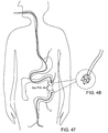
- the target tissue region may include a region within a patient's breast having a lesion therein, and the target may be delivered into or around the lesion.
- the target tissue region may be located in other regions of the body, e.g.., within or around the intestines, fallopian tubes, and the like.
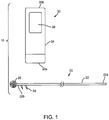
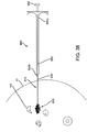
- FIG. 1 shows an exemplary embodiment of a system 10 for localization of a target tissue region within a patient's body, such as a tumor, lesion, or other tissue structure within a breast or other location within a body.
- the system 10 generally includes a marker device or localization wire 20 and a probe 30 for detecting at least a portion of the localization wire 20 using electromagnetic pulses, waves, or other signals, such as radar.
- the localization wire 20 may include an elongated member or shaft 22 including a proximal end 22a, a distal end 22b, and a target 26 on the distal end 22b.
- the system 10 may include one or more additional localization wires and/or targets (not shown) in addition to localization wire 20.
- the shaft 22 may be formed from a relatively rigid material, e.g., a solid rod or hollow tubular body, having sufficient column strength to facilitate percutaneous introduction of the localization wire 20 through tissue.
- the shaft 22 may have a length sufficient to extend from a location outside a patient's body through tissue to a target tissue region, e.g., between about half and ten centimeters (0.5-10 cm).
- the shaft 22 may be malleable or otherwise plastically deformable, e.g., such that the shaft 22 may be bent or otherwise formed into a desired shape, if desired.
- the target 26 may include one or more features on the distal end 22b of the shaft 22 to facilitate localization of the distal end 22b using the probe 30.
- the target 26 may be a bulbous structure, e.g., a sphere having a larger diameter than the distal end 22b of the shaft 22, e.g., between about half and five millimeters (0.5-5 mm).
- the target 26 may include one or more features to enhance electromagnetic signal reception and reflection.
- the target 26 may be formed from one or more materials and/or may have a surface finish that enhances detection by radar, e.g., similar to the markers described elsewhere herein.
- shapes and/or geometries may be provided, e.g., cubes, triangles, helixes, and the like, including one or more corners and/or edges that may enhance radar reflection and/or detection, similar to other embodiments herein.
- the target 26 may have a size and/or shape approximating the size and/or shape of the lesion 42, e.g., to facilitate identifying a desired margin around the lesion 42.
- the size and/or shape of the lesion 42 may be determined in advance, and a target 26 may be selected from a set of different size and/or shape targets and secured to the shaft 22 (or each target may be provided on its own shaft).
- each target may have a different shape and/or features, e.g., to facilitate distinguishing the targets from one another using the probe 30.
- the shaft 22 and target 26 may be integrally formed from the same material.
- the target 26 may be formed from different material(s) than the shaft 22, and the target 26 may be secured to the distal end 22b, e.g., by bonding with adhesive, welding, soldering, interference fit, threads or other cooperating connectors, and the like.
- the target 26 may be formed from material that enhances detection by radar relative to the shaft 22.
- each target may have a surface, shape, and/or additional material feature that may distinguish a particular target relative to one or more others.
- each target may absorb or reflect a particular electromagnetic signal that is specific to that target and can be used to uniquely identify it.
- the localization wire 20 may include one or more anchoring elements 24 on the distal end 22b, e.g., adjacent the target 26, although the target 26 itself may stabilize the localization wire 20 sufficiently that anchoring elements 24 may be unnecessary.
- the anchoring elements 24 include a plurality of barbs 24 (two shown) that extend transversely from the shaft 22, e.g., angled proximally away from the target 26.
- the barbs 24 may be configured for anchoring the localization wire 20 in position after the localization wire 20 is inserted into tissue, e.g., allowing the localization wire 20 to be advanced distally through tissue while preventing subsequent proximal withdrawal.
- the barbs 24 may be sufficiently flexible such that the barbs 24 may be compressed against or otherwise adjacent the shaft 22, e.g., to minimize a profile of the localization wire 20 to facilitate advancement, yet resiliently biased to return outwardly to a transverse orientation, as shown.
- the probe 30 may be a portable device having electromagnetic signal emitting and receiving capabilities, e.g., a micro-power impulse radar (MIR) probe.
- MIR micro-power impulse radar
- the probe 30 may be a handheld device including a first end 30a intended to be placed against or adjacent tissue, e.g., a patient's skin or underlying tissue, and a second opposite end 30b, e.g., which may be held by a user.
- the probe 30 generally includes one or more antennas, e.g., a transmit antenna 32 and a receive antenna 34, one or more processors or controllers 36, and a display 38.
- the processor 36 may include one or more controllers, circuits, signal generators, gates, and the like (not shown) needed to generate signals for transmission by the transmit antenna 32 and/or to process signals received from the receive antenna 34.
- the components of the processor 36 may include discrete components, solid state devices, programmable devices, software components, and the like, as desired.
- the probe 30 may include an impulse generator 36b, e.g., a pulse generator and/or pseudo noise generator (not shown), coupled to the transmit antenna 32 to generate transmit signals, and an impulse receiver 36c for receiving signals detected by the receive antenna 34.
- the processor 36 may include a micro controller 36a and a range gate control 36d that alternately activate the impulse generator 36b and impulse receiver 36c to transmit electromagnetic pulses, waves, or other signals via the antenna 32, and then receive any reflected electromagnetic signals via antenna 34.
- Exemplary signals that may be used include microwave, radio waves, such as micro-impulse radar signals, e.g., in the Ultra Low bandwidth region.
- each of the antennas 32, 34 may be a UWB antenna, e.g., a horn obtrusive physical profile, a dipole and patch, or a co-planar antenna, such as a diamond dipole antenna, a single ended elliptical antenna ("SEA"), a patch antenna, and the like.
- the processor 36 may activate a single antenna to operate alternately as a transmit antenna and a receive antenna (not shown) instead of providing separate antennas 32, 34.
- each antenna 32, 34 may be a TEM horn antenna, such as that disclosed in " TEM Horn Antenna for Ultra-Wide Band Microwave Breast Imaging,” published in Progress in Electromagnetics Research B, Vol. 13, 59-74 (2009 ).
- each antenna 32, 34 may be a patch antenna, such as those disclosed in U.S. Publication No. 2008/ 0071169, published March 20, 2008 , and in " Wideband Microstrip Patch Antenna Design for Breast Cancer Tumour Detection,” by Nilavalan, et al., published in Microwaves, Antennas, & Propagation, IET, Volume 1, Issue 2 (April 2007), pp. 277-281 .
- the patch antenna may be coupled to an enclosure (not shown), e.g., filled with dielectric material, to facilitate use with micro-impulse radar.
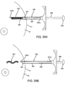
- each antenna may be a waveguide horn, e.g., as shown in FIG. 10B .
- antenna 32' includes a casing 32A that is closed on a first end 32B, and open on a second end 32C, and within which a waveguide 32D is mounted.
- the walls of the casing 32A may be lined with an absorber material 32E, e.g., a broadband silicone absorber material, such as Eccosorb-FGM40, sold by Emerson & Cuming Microwave Products N.V. of Westerlo, Belgium.
- the volume within the casing 32A may be filled with a dielectric 32F, e.g., having a relative permittivity of 10.
- the antenna 32' may be a square waveguide horn configured to operate at ultrawide band frequencies 9"UWB") between about three and ten Gigahertz (3-10 Ghz), e.g., having a width of about fifteen by fifteen millimeters (15x15 mm), and a length between the first and second ends 32B-32C of about thirty millimeters (30 mm).
- the open end 32B may be oriented outwardly from a probe within which the antenna 32' is mounted, e.g., such that the open end 32B may contact or otherwise be coupled with tissue through which the antenna 32' is intended to transmit and/or receive signals, as described elsewhere herein.
- the signals from the impulse receiver 36c may be filtered or otherwise processed, e.g., by a return signal de-clutter and shaper circuit 36e, before being communicated to the micro-controller 36a for further processing, display, storage, transmission, and the like.
- the circuit 36e may receive signals from the antenna 34, e.g., return echo noise and clutter, may de-clutter the signals, e.g., using LPF, and/or may include digital adaptive filtering and/or pulse shapers, as desired.
- the micro-controller 36a may then interpret the received and/or processed signals to identify a spatial relationship, e.g., distance, angle, orientation, and the like, of the target 26 or other structures relative to the probe 30, as described further below. Exemplary embodiments of processors and/or other components that may be included in the probe 30 are disclosed in U.S. Patent Nos. 5,573,012 and 5,766,208, issued to McEwan .
- the probe 30 may be configured to operate as a magneto-radar system, such as that disclosed in U.S. Patent No. 6,914,552, issued to McEwan .
- the probe 30 may include a magnetic field excitation source, e.g., an electromagnet (not shown), coupled to a generator and/or current coil driver (not shown), which may be provided within or external to the probe 30.
- the probe may induce a magnetic field to a marker or other target, generating a pole to pole vibration at a specific frequency that the radar unit may identify and/or recognize to provide a distance measurement or location coordinates.
- a probe may be useful when the target is implanted in tissue, bone, or bodily fluid with a relatively high impedance or dielectric constant that may attenuate the radar pulse from reaching the target or the reflected signal from reaching the radar antenna.
- the probe's display 38 may be coupled to the micro-controller 36a for displaying information to a user of the probe 30, e.g., spatial or image data obtained via the antenna(s) 32, 34.
- the display 38 may simply be a readout providing distance, angle, orientation, and/or other data based on predetermined criteria, e.g., based on the relative location of the target 26 to the probe 30, as described further below.
- FIG. 10A shows an exemplary embodiment of an output for display 38 that may be provided, which may include an array of arrows or other indicators 38a and a distance readout 38b.
- the micro-controller 36a may analyze the received signals to determine in which direction relative to the probe 30 a marker (not shown) may be located and activate the appropriate arrow 38a, and display a distance (e.g., "3 cm” shown) to the marker.
- a distance e.g., "3 cm” shown
- the user may be able to identify in what direction and how far in that direction the marker is located, thereby providing the user guidance towards the marker and the target tissue region within which the marker is implanted.
- the display 38 may provide other information, e.g., real-time images of the region towards which the probe 30 is oriented, i.e., beyond the first end 30a, operational parameters of the probe 30, and the like.
- the probe 30 may include one or more other output devices in addition to or instead of the display 38.
- the probe 30 may include one or more speakers (not shown) that may provide audio output, one or more LEDs or other light sources that provide visual output, and the like e.g., to provide information such as spatial information, operation parameters, and the like.
- a speaker or LED may be activated when the probe 30 reaches a predetermined threshold distance from the marker, e.g., a desired margin, or may be activated when successively closer distances are achieved.
- the probe 30 may include other features or components, such as one or more user interfaces, memory, transmitters, receivers, connectors, cables, power sources, and the like (not shown).
- the probe 30 may include one or more batteries or other internal power sources for operating the components of the probe 30.
- the probe 30 may include a cable (not shown) that may be coupled to an external power source, e.g., standard AC power, for operating the components of the probe 30.
- the user controls 37 may include one or more input devices, such as a keypad, touch screen, individual buttons, and the like (not shown).
- the user controls 37 may allow the user to perform simple operations, e.g., turn the probe 30 on and off, reset the probe 30, and the like, or may allow more complicated control of the probe 30.
- the user controls 37 may allow the sensitivity or other parameters of the probe 30 to be adjusted, may allow data to be captured, stored, transmitted remotely, and the like.
- the probe 30 may include internal memory 36f that may record or otherwise store data obtained via the antenna(s) 32, 34 and/or micro-controller 36a.
- the micro-controller 36a may automatically record data during operation, or may be instructed to selectively save data to the memory 36f.
- the micro-controller 36a may transfer data to one or more external devices, e.g., for storage, display, and the like.
- the probe 30 may include one or more cables (not shown) to allow such data transfer and/or the probe 30 may include a transmitter and/or receiver (not shown) for wirelessly transferring data and/or receiving commands, e.g., via radio frequency, infrared, or other signals.
- the internal components of the probe 30 may be provided in a housing or casing 39 such that the probe 30 is self-contained.
- the casing 39 may be relatively small and portable, e.g., such that the entire probe 30 may be held in a user's hand.
- the first end 30a of the casing 39 may be formed from like or different materials than other portions of the casing 39.
- the first end 30a may be formed from materials that easily accommodate passage of electromagnetic signals therethrough, e.g., from the transmit antenna 32 and/or to the receive antenna 34, without substantial interference.
- the materials may be selected to reduce interference, match impedance, or otherwise facilitate transmitting and receiving signals via the probe 30 into and out of a patient's body.
- the probe 30 may include a handle, finger grips, and/or other features (not shown) to facilitate holding or otherwise manipulating the probe 30.
- a probe instrument 130 may be provided that includes a separate controller 139 including one or more of the components within a casing remote from a handheld probe 131.
- the handheld probe 131 may include an elongate housing 131a including a tip 131b with one or more antennas 132.
- the controller 139 may include one or more processors for controlling the antenna(s) 132, a display 138, and the like, similar to the previous embodiments.
- the handheld probe 131 may be coupled to the processor(s) in the controller 139 by one or more cables 133.
- an impulse generator, impulse receiver, and/or gate control may be provided within the casing of the controller 139 or, optionally, within the housing 131a, if desired.
- the cable 133 may be removably connectable to a connector (not shown) on the controller 139 for electrically coupling the antenna 132 of the handheld probe 131 to the electronics within the controller 139.
- the handheld probe 131 may be a disposable, single-use device while the controller 139 may be used during multiple procedures by connecting a new handheld probe 131 to the controller 139, which may remain out of the surgical field yet remain accessible and/or visible, as desired, as explained further below.
- the localization system 10 of FIG. 1 may be used during a medical procedure, for example, in a breast biopsy or lumpectomy procedure, e.g., to facilitate localization of a lesion or other target tissue region 42 and/or to facilitate dissection and/or removal of a specimen from a breast 41 or other body structure.
- a medical procedure for example, in a breast biopsy or lumpectomy procedure, e.g., to facilitate localization of a lesion or other target tissue region 42 and/or to facilitate dissection and/or removal of a specimen from a breast 41 or other body structure.
- the system 10 is described as being particularly useful in localization of breast lesions, the system 10 can also be used in localization of other objects in other areas of the body, e.g., as described elsewhere herein.
- a target tissue region e.g., a tumor or other lesion
- a lesion 42 within a breast 41 may be identified, e.g., using mammography and/or other imaging, and a decision may be made to remove the lesion 42.
- the dashed line 44 surrounding the tumor 42 defines a "clear" margin, e.g., indicating the size and shape of a desired tissue specimen 46 that is to be removed during the procedure.
- the margin 44 may be selected to ensure that the remaining tissue after removing the specimen 46 is substantially clear of cancerous or other undesired cells.
- the distance between the outer boundaries of the lesion 42 and the outer edges or margin 44 of the tissue specimen 46 may be between about one and ten millimeters (1-10 mm), e.g., at least about two millimeters (2 mm) or at least about one centimeter (1 cm).
- the localization wire 20 may be introduced percutaneously through tissue 40, e.g., from the patient's skin 48 through intervening tissue until the target 26 is positioned within the lesion 42.
- the localization wire 20 may be introduced through a delivery sheath (not shown), which may be placed previously using a needle and/or dilator (also not shown), similar to the cannula 340 described with reference to FIGS. 20-22 elsewhere herein.
- a cannula or delivery sheath having a sharpened tip may be penetrated through the skin 48 and intervening tissue 40 into the lesion 42, e.g., using ultrasound or x-ray imaging for guidance, and then the localization wire 20 may be advanced through the cannula.
- a needle having a sharpened tip may be advanced through tissue and then a delivery sheath may be advanced over the needle (not shown), e.g., along with a dilator between the needle and delivery sheath. Once the delivery sheath is positioned such that it extends from the skin 48 to the lesion 42, the needle and any dilator may be removed.
- the distal end 22b of the localization wire 22 may then be advanced through the delivery sheath until the target 26 is positioned within the lesion 42, whereupon the delivery sheath may be removed.
- the localization wire 22 may include one or more markers (not shown) on the distal end, e.g., radiopaque or echogenic markers, on or adjacent the target 26, to facilitate imaging the target 26 and/or distal end 22b of the localization wire 22. External imaging may then be used during and/or after introduction of the localization wire 20 to ensure that the target 26 is properly positioned within the lesion 42.
- the localization wire 20 includes anchoring element(s), such as barbs 24, the barbs 24 may be compressed inwardly when the localization wire 20 is advanced through the delivery sheath. Once the target 26 is positioned within the lesion 42, the delivery sheath may be withdrawn, whereupon the barbs 24 may resiliently expand outwardly into the adjacent tissue. Thus, the barbs 24 on the distal end 22b of the shaft 22 may anchor the localization wire 20 relative to the lesion 42, e.g., such the target 26 may be substantially secured in a fixed position within the lesion 42.
- anchoring element(s) such as barbs 24
- a bandage, tape, and the like may be used to secure the proximal end 22a of the localization wire 22a to the patient's skin 48, e.g., to prevent migration of the localization wire 22.
- the first end 30a of the probe 30 may be placed adjacent or in contact with the patient's skin 48, e.g., generally above the lesion 42, and/or otherwise aimed generally towards the target 26, and activated, as shown in FIG. 3 .
- the transmit antenna 32 (not shown, see FIG. 10 ) of the probe 30 may emit electromagnetic signals 31 that travel through the tissue 40 and are reflected off of the target 26.
- the signals 33 may be reflected back to the receive antenna 34 (not shown, see FIG. 10 ) in the probe 30.
- the probe 30 may then determine a spatial relationship between the target 26 and the first end 30a of the probe 30, e.g., a distance 52 between the target 26 and the probe 30 (and the patient's skin 48 if contacted by the first end 30a of the probe 30), e.g., based on the distance traveled by the signals 31, passage of time between transmission of signals 31 and reception of reflected signals 33, and the like.
- the probe 30 may also determine a relative angle between the target 26 and the first end 30a, e.g., to facilitate determining a proper direction of dissection.
- the micro-controller 36a (not shown, see FIG. 10 ) of the probe 30 may filter or otherwise analyze received signals to identify the target 26, e.g., based on recognition of the size, shape, or other aspects of the target 26.
- the micro-controller 36a may automatically be able to identify the target 26 and distinguish it from other structures that may be present in the patient's body.
- the micro-controller 36a may simply identify any objects reflecting signals back to the probe 30, which presumably would identify the target 26.
- the micro-controller 36a may calculate the distance 52 and/or an angle relative to an axis extending orthogonally from the first end 30a of the probe 30, and display this spatial information on the display 38.
- This information may facilitate localizing the target 26, and consequently the lesion 42, which may provide guidance to a surgeon dissecting tissue overlying the lesion 42, e.g., by providing a direction and depth of dissection to access the target tissue region including the lesion 42.
- the display 38 may provide a distance 54 between the target 26 and the outer margin 44 of the target tissue specimen 46, which may facilitate defining the targeted size and shape of the tissue specimen 46 to be removed.
- the probe 30 may automatically subtract a predetermined distance between the desired margin 44 and the target 42, e.g., based on preset parameters programmed into the processor 36 of the probe 30 or based on dimensions provided to the micro-controller 36a by the user immediately before the procedure, e.g., via user controls 37 (not shown, see FIG. 10 ).
- the probe 30 may be positioned at several locations against or otherwise adjacent the skin 48 and spatial information obtained, if desired. Such information may facilitate the surgeon determining an optimal approach path for dissection, e.g., the shortest path to the lesion 42, or otherwise help orient the surgeon relative to the lesion 42 in three dimensions.
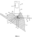
- the tissue 40 may be dissected to reach the predetermined outer edge 44 of the tissue specimen 46, as shown in FIG. 4 .
- an incision may be made in the patient's skin 48 at the location where the probe 30 was placed and the intervening tissue dissected using known methods until the depth corresponding to the margin 44 is achieved.
- the probe 30 may be placed against or adjacent the exposed tissue and spatial information obtained to confirm the approach and/or depth of dissection.
- the tissue specimen 46 may be excised or otherwise removed using conventional lumpectomy procedures with the target 26 remaining within the removed specimen 46. If desired, the target 26 may be separated from the shaft 22 to facilitate removal of the specimen 46, e.g., by cutting the distal end 22b of the shaft 22, by disconnecting any connectors (not shown) between the shaft 22 and target 26, and the like.
- the probe 30 may be used to analyze the excised tissue specimen 46, e.g., to confirm that the desired margin 44 has been achieved around the target 26, and consequently around the lesion 42.
- transmit signals 31 are transmitted by the probe 30 and signals 33 are reflected off the target 26 and received by the probe 30, whereupon the probe 30 may determine and display the distance 54 and/or any other spatial information. In this manner, it can be verified that the predetermined tissue margin has been achieved.
- FIGS. 6-9 another exemplary embodiment of a system 110 for localizing a lesion or other tissue structure, e.g., a plurality of non-palpable lesions 142, is shown that includes a probe 30 and a plurality of implantable markers or targets 120.
- the probe 30 may be a portable device capable of transmitting electromagnetic signals and receiving reflected signals, similar to the embodiments described elsewhere herein.
- the markers 120 may include a plurality of implantable elements sized for introduction through tissue into a region surrounding the lesion 142.
- the markers 120 may be formed as a plurality of strips, cylinders, helixes, spheres, and the like, e.g., having features to enhance reflection of electromagnetic signals transmitted by the probe 30, similar to the target 26 described above with reference to FIG. 1 and/or the markers described further elsewhere herein, e.g., with reference to FIGS. 23A-28C , 34A, 34B, 41A, and 41B .
- the markers 120 may be elongate strips, e.g., rectangular or other shaped markers having a length between about half to four millimeters (0.5-4.0 mm), a width between about half and two millimeters (0.5-2.0 mm), and a thickness between about half and three millimeters (0.5-3.0 mm).
- the markers 120 may be formed from metal or other material that may enhance detection by the probe 30, e.g., having a desired dielectric constant.
- the markers 120 may be formed from bioabsorbable material, e.g., such that the markers 120 may be implanted within tissue and then dissolved or otherwise absorbed by the tissue over time, e.g., over several days, weeks, or months.
- the markers 120 may be formed from radiopaque material, radioactive material, and/or echogenic material, which may facilitate imaging or otherwise monitoring the markers 120, e.g., during introduction, after placement during a procedure, or afterwards if the markers 120 remain within the patient's body after the procedure.
- each marker 120 may have a surface, shape, and/or additional material feature that may distinguish one or more of the markers from others, as described elsewhere herein.
- each marker 120 may modulate an incident signal from the probe 30 in a predetermined manner and/or absorb or reflect a particular electromagnetic signal that is specific to that marker 120 and may be used to uniquely identify it.
- the system 110 may also include one or more delivery devices 160 for introducing the markers 120 into a patient's body.
- a delivery device 160 may be provided that includes a shaft 162 including a proximal end 162a and a distal end 162b sized for introduction through tissue into a target tissue region (not shown) and carrying one or more markers 120.
- the delivery device 160 may include a lumen 164 extending at least partially between the proximal and distal ends 162a, 162b of the shaft 162, and a pusher member 166 slidable within the shaft 162 for selectively delivering one or more markers 120 successively or otherwise independently from the lumen 164.
- the distal end 162b of the shaft 162 may be beveled and/or otherwise sharpened such that the shaft 162 may be introduced directly through tissue.
- the delivery device 160 may be introduced through a cannula, sheath, or other tubular member (not shown) previously placed through tissue, e.g., as described elsewhere herein.
- the distal end 162b may include a band or other feature, e.g., formed from radiopaque, echogenic, or other material, which may facilitate monitoring the distal end 162b during introduction, e.g., using fluoroscopy, ultrasound, electromagnetic signals, and the like.
- the pusher member 166 includes a piston or other element (not shown) disposed within the lumen 164 adjacent the marker(s) 120 and a plunger or other actuator 168 coupled to the piston for advancing the piston to push the marker(s) 120 from the lumen 164.
- the plunger 168 may be manually advanced to deliver one or more markers 120 successively from the lumen 164.
- a trigger device or other automated actuator may be provided on the proximal end 162b of the shaft 162, which may advance the piston sufficiently with each activation, e.g., to delivery an individual marker 120 from the distal end 162b.
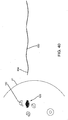
- an exemplary method is shown for using the markers 120 and probe 30 to localize a lesion or other target tissue region 142 within a breast 41 or other tissue structure.
- the markers 120 may be implanted within the tissue 40 to delineate a desired margin or volume 144 of a tissue specimen 146 to be excised.
- the shaft 162 of the delivery device 160 may be inserted percutaneously through the patient's skin 48, through any intervening tissue 40, and the distal end 162b positioned within or around the lesion 142, e.g., using external imaging to guide the distal end 162b to a desired location.
- the plunger 168 may be advanced (or the shaft 162 withdrawn relative to the plunger 168) to deliver a marker 120 into the tissue.
- the delivery device 160 may be advanced further to another location and/or removed entirely from the breast 41 and reintroduced through another location of the skin 48 into the target tissue region, e.g., to deliver one or more additional markers 120.
- the delivery device 160 may carry only a single marker 120, and multiple delivery devices (not shown) may be provided for delivering each of the markers 120.
- a stereotactic device (not shown) may be used, e.g., to introduce one or multiple delivery devices into the patient's body in a desired three-dimensional array or other arrangement for localizing the lesion 142.
- the markers 120 may be replaced with multiple localization wires, similar to wire 10, one or more catheters (not shown) which may be delivered sequentially, simultaneously, and the like.
- the catheter(s), wire(s), or other devices may be expandable, e.g., at a distal region (not shown) to facilitate dilating and/or identifying a specimen volume or region.
- the markers 120 surround a group of non-palpable lesions 142, e.g., before or during a procedure to remove a specimen volume surrounding the lesions 142.
- the distance 156 between the outer edge 144 of the tissue specimen 146 and the lesions 142 may be selected to ensure that the volume of tissue removed is sufficient to ensure clear margins, similar to the methods described above.
- the probe 30 may be placed against or otherwise adjacent the patient's skin 48 (e.g., it may be unnecessary to contact the patient's skin 48 with the probe 30 to transmit and receive signals into and from the tissue 40), and the probe 30 may be used to determine the distance 152 (and/or other spatial information) between the probe 30 and the markers 120, similar to the previous embodiments.
- the signals 31 emitted by the probe 30 may be received at the markers 120 and reflected back to a receiver in the probe 30 as signals 33, and the probe 30 may use the signals to determine the distance 152 between the patient's skin 48 and the markers 120.
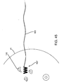
- the tissue 40 surrounding the lesions 142 may then be dissected until one of the markers 120 is encountered, as shown in FIG. 8 . At this point, another measurement may be taken with the probe 30 to ensure proper dissection depth. The probe 30 may then be repositioned, as shown in phantom in FIG. 8 , to locate another one of the markers 120 around the periphery 144 of the tissue specimen 146. The resulting distance measurements may be used to determine a desired margin volume for excision around the lesions 142. This process may be repeated as often as desired to facilitate measuring the desired margin based on the distance to the markers 120 during excision of the tissue specimen 146 around the lesions 142.
- the tissue specimen 146 may include the markers 120 therein such that all of the markers 120 are removed with the tissue specimen 146.
- the desired margin may be defined within the markers 120 such that the markers 120 remain within the breast after the tissue specimen 120 is removed.
- the markers 120 may be bioabsorbable or may be inert and remain indefinitely within the patient's breast 41.
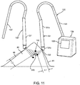
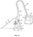
- FIGS. 11-15 another exemplary system and method are shown for localizing one or more lesions 142 within a breast 41 and/or removing a tissue specimen 146 (shown in FIGS. 14A-15A ) including the lesion(s) 142.
- the system includes one or more markers 220 and a probe instrument 130, which may facilitate localizing the lesion(s) 142 and/or ensuring desired margins are achieved for the tissue specimen 146 removed from the breast 41.
- the probe instrument 130 includes a handheld probe 131 coupled to a processor 139 including one or more processors for controlling operation of the probe 131, as described above.
- the handheld probe 131 includes an elongate housing 131a including one or more antennas 132 on or within a tip 131b on one end of the probe 131 that may be placed against the skin 48 or other tissue and/or otherwise oriented generally towards the marker 220 and/or lesion(s) 142.
- the processor 139 may include one or more processors for controlling the antenna(s) 132, a display 138, and the like, similar to the previous embodiments.
- the handheld probe 131 may be coupled to the processor 139 by one or more cables 133.
- an impulse generator, impulse receiver, and/or gate control may be provided within the processor 139, which may be controlled to emit and receive signals via the antenna(s) 132.
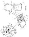
- the handheld probe 131 may include a dissecting feature 133, e.g., extending from the tip 131b of the housing 131a.
- the dissecting feature 133 may be a relatively flat blunt dissector fixed to the tip 131b of the probe 131, e.g., having a length of about ten to fifty millimeters (10-50 mm) and/or a width of about one to ten millimeters (1-10 mm).
- the dissecting feature 133 may be retractable, e.g., such that the dissecting feature 133 may be initially retracted within the housing 131a, but may be selectively deployed when desired to dissect layers of tissue to access tissue adjacent the marker 220.
- the dissecting feature 133 may include a sharpened blade or edge, which may facilitate cutting through the patient's skin 48 and/or underlying layers of tissue 40.
- one or more markers 220 may be implanted within the target tissue region, e.g., using the markers and/or methods described elsewhere herein.
- the probe 131 may be coupled to the processor 139, e.g., by cable 133, and the tip 131b placed against the skin 48.
- the probe 131 may be activated, e.g., to obtain an initial distance measurement from the tip 131b of the probe 131 to the marker 220 using the antenna(s) 132, thereby providing an approximate distance to the lesion(s) 142.
- the distance measurement may be displayed on the display 138 of the processor 139, e.g., as shown in FIG. 12 , and/or otherwise provided to the user.
- a speaker may provide the distance measurement, e.g., using a synthesized voice, one or more tones identifying corresponding distances, and the like, to identify the distance.
- the processor 139 may analyze the received signals to determine the actual distance from the tip 131b of the probe 131 to the marker 220, and may provide the actual measurement via the speaker.
- the speaker may provide a tone corresponding to a predetermined threshold, e.g., a first tone for a first threshold distance, a second tone or multiple tones for a second, closer distance, and the like, thereby indicating to the user that they are getting closer to the marker 220.
- a measurement L1 is obtained, while with the probe 131' placed on a second opposite side of the breast 41, a measurement L2 is obtained, which is greater than L1.
- the physician may decide to initiate dissection on the first side since it provides a shorter path requiring less tissue dissection than a path initiated from the second side, as shown in FIG. 12 .
- the probe 131 may be used to identify a desired margin L3 around the marker 220 and consequently around the lesion(s) 142. For example, if a desired margin L3 of one centimeter (1 cm) is desired, the probe 131 may be display or otherwise provide the actual distance L1 from the probe 131 to the marker, as shown on the display 138, thereby indicating that the probe 131 remains outside the margin L3. Alternatively, if the processor 139 knows the desired margin L3, the display 138 may provide the difference between the actual distance L1 and the desired margin L3 (i.e., L1-L3), thereby informing the physician of the depth of dissection necessary to attain the desired margin.
- L1-L3 the difference between the actual distance L1 and the desired margin L3
- the blunt dissector 144 may be deployed from the tip 131b of the probe 131 (if not permanently deployed) and advanced through the tissue 40 towards the marker 220, e.g., until the desired margin L3 is attained.
- the probe 131 may then be manipulated to dissect tissue around the marker 220 using the blunt dissector 144 and/or using one or more additional dissectors, scalpels, or other tools (not shown).
- a tissue specimen 146 has been removed from the breast 41 that includes the marker 220 and the lesion(s) 142 therein.
- the probe 131 may then be used to confirm that the desired margin L3 was achieved around the marker 220, thereby providing confirmation that sufficient tissue has been removed from the breast 41, similar to the previous embodiments.
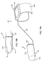
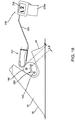
- FIGS. 16A and 16B still another embodiment of a system is shown that includes one or more markers 220, a probe 231 including a finger cot 231a carrying one or more antennas 232, and a processor 239 coupled to the antenna(s) 232, e.g., by cable 233.
- the finger cot 231a may be a flexible sleeve, e.g., including an open end 231b into which a finger 90 may be inserted, a closed end 231c, and having sufficient length to be securely received over the finger 90.
- the finger cot 231a may be formed from elastic material, such as a relatively thin layer of latex, natural or synthetic rubber, and the like, e.g., similar to surgical or examination gloves, having sufficient flexibility to expand to accommodate receiving the finger 90 while compressing inwardly to prevent the finger cot from 231a sliding off the finger 90 during use.
- elastic material such as a relatively thin layer of latex, natural or synthetic rubber, and the like, e.g., similar to surgical or examination gloves, having sufficient flexibility to expand to accommodate receiving the finger 90 while compressing inwardly to prevent the finger cot from 231a sliding off the finger 90 during use.
- the antenna(s) 232 may be provided adjacent the closed end 231c, as shown.
- the antenna(s) 232 may include a transmit antenna and a receive antenna (not shown), similar to the previous embodiments, provided within a casing.
- the casing may be attached to the finger cot 231a, e.g., adjacent the closed end 231c, for example, by bonding with adhesive, fusing, one or more overlying bands (not shown), and the like.
- the processor 239 may include one or more components for operating the antenna(s) 232 and/or processing signals received from the antenna(s) 232, e.g., coupled to the antenna(s) 232 by cable 233 and including display 238, similar to the previous embodiments.
- the processor 239 includes one or more clips 239a, straps, belts, clamps, or other features (not shown) that allow the processor 239 to be removably secured to the arm of a user whose finger is inserted into the finger cot 231a.
- the clips 239a may be curved to extend partially around a user's forearm, and the clips 239a may be sufficiently flexible to open them to receive an arm therein and then resiliently close to engage at least partially around the arm.
- the processor 239 may be provided in a casing (not shown) that may be placed remotely from the patient and/or user, e.g., similar to the processor 139 described above.
- a physician or other user may insert one of their fingers 90, e.g., their index finger or thumb, into the finger cot 231a, and the processor 239 may be activated to send and receive signals via the antenna(s) 232, similar to the previous embodiments.
- the finger 90 inserted into the finger cot 231a may be placed against the patient's skin 48 and distance measurements obtained to identify the distance to the marker 220.
- the user may insert the finger 90 into the path created, as shown in FIG. 18 , thereby providing direct feedback to the user of the location of the marker 220, and consequently, the lesion(s) 142, relative to the finger 90.
- this embodiment of the probe 231 may provide tactile feedback as well as distance measurements, which may facilitate dissection and/or removal of a tissue specimen 146 including the marker 220 and lesion(s) 142 therein. For example, as shown in FIG.
- an initial distance measurement L1 may be obtained informing the user of the depth of dissection needed, while, as shown in FIG. 18 , a distance measurement L2 may be obtained (corresponding to the desired margin), thereby informing the user that sufficient dissection has been achieved and the tissue specimen 146 may be isolated and removed, similar to the previous embodiments.
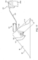
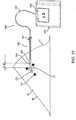
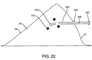
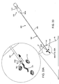
- the system includes a probe instrument 330, including a handheld probe 331 coupled to a processor 339, similar to the previous embodiments.
- the probe 331 includes one or more antennas 332, and the processor 238 includes a display 338.
- the system includes a cannula or other tubular member 340 that includes a proximal end 342, distal end 344, and a lumen 346 extending therebetween.
- the cannula 340 may be a substantially rigid tubular body having a size such that the probe 331 may be received within the lumen 346, as shown in FIG. 19 .
- the distal end 344 may be beveled, sharpened, and/or otherwise formed to facilitate advancement directly through tissue.
- the distal end 344 may be tapered and/or rounded (not shown), e.g., such that the cannula 340 may be advanced over a needle (not shown) either before or after the needle has been introduced into the tissue 40, similar to the previous embodiments.
- the probe 330 may be inserted into the lumen 346 of the cannula 340, e.g., such that the antenna(s) 332 are disposed immediately adjacent the distal end 344 of the cannula 340.
- the cannula 340 and/or probe 331 may include one or more connectors (not shown) for releasably securing the probe 331 relative to the cannula 340, e.g., to maintain the antenna(s) 332 adjacent the distal end 344, while allowing the probe 331 to be removed when desired.
- the cannula 340 may include one or more seals (not shown), e.g., within the proximal end 342 and/or distal end 344, to provide a substantially fluid-tight seal when the probe 331 is disposed within the lumen 346 and/or when the probe 331 is removed.
- a hemostatic seal (not shown) may be provided in the proximal end 342 that may provide a seal to prevent fluid flow through the lumen 346, yet accommodate receiving the probe 331 or other instruments (not shown) therethrough.
- the distal end 344 of the cannula 340 may be inserted through the patient's skin 48 and tissue 40 towards the marker 220.
- the probe 331 may transmit signals 31 and the display 338 of the processor 339 may provide a distance measurement L1 or other indication of the relative location of the marker 220 to the antenna(s) 332 based on the reflected signals received by the antenna(s) 332, and consequently, relative to the distal end 344 of the cannula 340.
- the depth of penetration and/or direction of advancement of the cannula 340 may be adjusted based upon the information provided by the probe 331 and processor 339.
- the cannula 340 may be advanced until a desired distance L2 is achieved, thereby placing the distal end 344 a desired distance away from the marker 220, e.g., within a target tissue region adjacent the lesion(s) 142.
- the probe 331 may be removed, leaving the cannula 340 in place, as shown.
- the cannula 340 may thereby provide a passage for accessing the target tissue region, e.g., to perform one or more diagnostic and/or therapeutic procedure.
- a needle or other tool (not shown) may be advanced through the lumen 346 of the cannula to perform a biopsy and/or to deliver fluids or other diagnostic or therapeutic material into the target tissue region.
- one or more instruments may be introduced through the cannula 340 for removing a tissue specimen, e.g., including the lesion(s) 142, for delivering radiation therapy, and/or other procedures.
- a tissue specimen e.g., including the lesion(s) 142
- the cannula 340 may simply be removed.
- the probe 331 may be reintroduced into the lumen 346 and the cannula 340 relocated within the tissue with the probe 331 providing additional guidance.
- markers 220 are shown, which may be implanted or otherwise placed within the tissue 40, e.g., within or otherwise adjacent the lesion(s) 142, using methods similar to those described above.
- the markers 220 are generally elongate bodies including relatively narrow middle stem portions between bulbous ends.
- the markers 220 may be formed from desired materials and/or may include surface features similar to other markers herein, which may facilitate localization of the markers 220 and/or distinguishing markers from one another.
- a first exemplary marker 320 is shown that includes a core wire 322 carrying a plurality of beads or segments 324.
- the core wire 322 may be an elongate member, e.g., a solid or hollow structure having a diameter or other maximum cross-section between about half and two millimeters (0.5-2 mm) and a length between about one and ten millimeters (1.0-10 mm).
- the core wire 322 may be formed from elastic or superelastic material and/or from shape memory material, e.g., stainless steel, Nitinol, and the like, such that the core wire 322 is biased to a predetermined shape when deployed within tissue, as explained further below.
- the core wire 322 may be substantially rigid such that the marker 320 remains in a fixed shape, e.g., linear or curved, as described further below.
- the beads 324 may include a plurality of individual annular bodies, e.g., each defining a portion of a generally cylindrical or spherical shape.
- the beads 324 may be formed from desired materials similar to the previous embodiments, e.g., metals, such as stainless steel, Nitinol, titanium, and the like, plastic materials, or composite materials.
- the beads 324 may be formed by injection molding, casting, machining, cutting, grinding base material, and the like.
- a desired finish may be applied to the beads 324, e.g., by sand blasting, etching, vapor deposition, and the like.
- each bead 324 may include a passage 326 therethrough for receiving the core wire 322 (not shown, see, e.g., FIGS. 23A-23C ) therethrough.
- the beads 324 may include shapes and/or surface features to allow the beads 324 to be nested at least partially adjacent one another when secured onto the core wire 322, yet allow the marker 320 to change shape, e.g., as the core wire 322 changes shape.
- each bead 324 may include a first convex or bulbous end 324a and a second concave end 324b including flat surfaces 324d. As shown in FIG.
- adjacent beads 324' may define recesses 324c' between the flat surfaces 324d' on the concave end 324b' of a first bead 324 and a surface 324e' on the bulbous end 324a' of the adjacent bead 324.
- the surfaces 324d' and 324e' may define abrupt corners therebetween, which may enhance detection using radar, e.g., defining angles of about ninety degrees (90°).
- the beads 324' may include a desired surface finish 324f intended to customize reflected signals generated when electromagnetic signals strike the surfaces of the beads 324.
- the surface finish 324f may include a plurality of pores or dimples formed in the beads 324' and having a desired diameter and/or depth.
- the probes and processors described elsewhere herein may analyze such reflected signals to uniquely identify a particular marker, e.g., when multiple markers are implanted or otherwise placed within a patient's body.
- a plurality of beads 324 may be placed over and secured to the core wire 322 to provide a finished marker 320.
- the core wire 322 may be inserted successively through the passages 326 in the beads 324 until beads 324 extend substantially between the ends of the core wire 322.
- the beads 324 may be secured to the core wire 322, e.g., by crimping individual beads 324 onto the core wire 322, crimping or otherwise expanding the ends of the core wire 322 after sliding on sufficient beads 324, bonding with adhesive, fusing, and the like.
- the beads 324 may be substantially permanently attached to the core wire 322 such that the beads 324 cannot move or the beads 324 may be free floating on the core wire 322, e.g., which may facilitate bending or otherwise shaping the core wire 322, and consequently the marker 320.
- the marker 320 may be formed from a single piece of material, e.g., such that the shapes and surfaces defined by the beads 324 shown in FIGS. 23A are formed in the workpiece.
- the core wire 322 may be eliminated, or a passage may be formed through the workpiece for receiving the core wire 322.
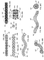
- the marker 320 may define a substantially fixed shape, e.g., a linear shape as shown in FIGS. 23A and 23B , or a curvilinear shape, as shown in FIGS. 23D and 26A-26C .
- the core wire 322 of the marker 320 may be sufficiently flexible such that the marker 320 may be straightened, e.g., to facilitate loading the marker 320 into a delivery device and/or otherwise delivering the marker 320, yet the marker 320 may be biased to a curvilinear or other nonlinear shape.
- the marker 320 may be biased to assume a wave configuration, e.g., a serpentine or other curved shape lying within a plane.
- the core wire 322 may be formed from elastic or superelastic material that is shape set such that the core wire 322 is biased to the wave configuration, yet may be resiliently straightened to a linear configuration.
- the beads 324 may be spaced apart or otherwise nested such that the beads 324 do not interfere substantially with the transformation of the core wire 322 between the linear and wave configurations, e.g., to facilitate loading the marker 320 into a delivery device and/or introducing the marker 320 into a body.
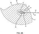
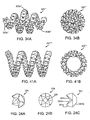
- a marker 320''' may be provided that is biased to assume a tapered helical shape, e.g., including a relatively wide intermediate region 320a''' between tapered end regions 320b.'''
- FIGS. 41A and 41B Another alternative embodiment of a marker 320'''' is shown in FIGS. 41A and 41B that is biased to assume a substantially uniform diameter helical shape.
- markers 320,'''' 320''''' may provide a relatively constant and/or consistent Radar Cross Section ("RCS") regardless of the reflective angle and/or position of the markers 320,'''' 320'''' relative to the antenna(s) of the probe (not shown).
- RCS Radar Cross Section
- the markers 320,''' 320"" may provide a RCS substantially similar to when viewed laterally relative to the helical axis, e.g., as viewed in FIGS. 34A and 41A .
- any of the markers described herein may be provided as a passive marker, an active marker, an active reflector, or an active transponder.
- the marker 320 may simply be a "passive reflector," i.e., the marker 320 may simply reflect incident waves or signals striking the marker 320. The incident signals may be reflected off of the various surfaces and/or edges of the marker 320, e.g., thereby providing reflected waves or signals that may be detected by a probe, as described further elsewhere herein.
- One disadvantage of a passive marker is that the Radar Cross Section (RCS) may change based on the aspect angle of the antenna of the probe and the marker 320, which may cause changes in the strength of the returned signal reflected from the marker 320.
- RCS Radar Cross Section
- the marker 320 may include one or more features to provide an "active reflector," i.e., a marker 320 that includes one or more electronic circuits that modulate signals striking the marker 320 in a predetermined manner without adding external energy or power to the reflected signals.
- a marker may include an active reflector radio element that includes a modulated dipole or other type of active reflector antenna, e.g., including one or more very low power diodes and/or FET transistors that require very little current to operate.
- the active reflector may provide a substantially unique radar signal signature in an embedded tissue environment that may be detected and identified by a probe.
- the active reflector may provide a relatively larger signal return to the probe, e.g., thereby maintaining a target RCS regardless of antenna aspect.
- the marker 320 may include one or more circuits or other elements (not shown) coupled to or embedded in the marker 320 that may modulate incident waves or signals from the probe.
- a nanoscale semiconductor chip may be carried by the marker 320 that does not include its own energy source and therefore merely processes and modulates the signals when they are received and reflected off the marker 320.
- active reflectors that may be provided on a marker are disclosed in U.S. Patent No. 6,492,933 .
- FIGS. 50A and 50B show an example of modulation of a reflected signal B relative to an incident signal A that may be achieved using an active reflector.
- Incident signal A may represent waves or signals transmitted by a probe (not shown), such as any of those described elsewhere herein.
- the incident signal A may strike and be reflected off of a surface, e.g., of any of the markers described herein, resulting in a reflected signal B.
- the surface of the marker may simply reflect the incident signal A, and therefore the reflected signal B may have similar properties, e.g., bandwidth, phase, and the like, as the incident signal A.
- the marker may modulate the incident signal A in a predetermined manner, for example, to change the frequency and/or phase of the reflected signal B.
- the circuit on the marker may change an ultrawide broadband radar incident signal A into a relatively narrow band reflected signal B, e.g., between about one and ten GigaHertz (1-10GHz), that also includes a predetermined phase shift.
- the relatively narrow band reflected signal B may enhance the RCS of the marker and thereby enhance detection by the probe.
- the phase of the reflected signal B has been modulated by ninety degrees (90°) relative to the incident signal A.
- the phase shift may facilitate the probe identifying and distinguishing the marker from other structures, e.g., other markers having a different phase shift, tissue structures, and the like.
- each marker's circuit may be configured to impose a different phase shift (e.g., +90°, +180°, -90°, and the like) and/or bandwidth in the reflected signal.
- the probe may be able to easily identify and distinguish the markers from each other and/or from other structures in the patient's body.
- the circuit does not require its own power source.
- the size of the circuit may be substantially reduced and, if desired, the marker may be implanted within a patient's body for an extended or even indefinite period of time, yet the marker may respond to signals from a probe to facilitate locating and/or identifying the marker.
- an "active marker” may be provided that includes one or more features that generate detectable energy in response to an excitation energy reference. Examples of such active markers are disclosed in U.S. Patent No. 6,363,940 .
- an active transponder may be provided, e.g., that retransmits or "transponds" the MIR probe's energy providing for a uniqueness of radar signal signature in an embedded tissue environment.
- the active transponder may include one or more electronic circuits embedded in or carried by the marker and including an internal energy source, e.g., one or more batteries, capacitors, and the like.
- the active transponder may include a microwave receiver and/or transmitter, a data processing and storage element, and a modulation system for the returned signal.
- the active transponder may generate microwave energy in response to excitation microwave energy emitted by the probe, e.g., to provide a larger signal return to the probe than would be possible with only a passive marker.
- the marker may generate RF energy including formatted data in response to a unique radar signature and/or frequency from the probe.
- the active transponder may be quadrature modulated to emit a single side band ("SSB") signal in either the Upper Sideband Band (“USB”) or the Lower Sideband ("LSB”) of the MIR radar.
- SSB single side band
- USB Upper Sideband Band
- LSB Lower Sideband
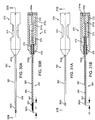
- a delivery device 260 may be provided that includes a shaft 262 including a proximal end 262a and a distal end 262b sized for introduction through tissue into a target tissue region, e.g., within breast 41, and carrying a marker 320 (or optionally multiple markers, not shown).
- the delivery device 260 may include a lumen 264 extending between the proximal and distal ends 262a, 262b of the shaft 262, and a pusher member 266 slidable within the shaft 262 for delivering the marker 320 of FIGS. 23A-23D from the lumen 264.
- the distal end 262b of the shaft 262 may be beveled and/or otherwise sharpened such that the shaft 262 may be introduced directly through tissue.
- the delivery device 260 may be introduced through a cannula, sheath, or other tubular member (not shown) placed through tissue, e.g., as described elsewhere herein.
- the distal end 262b may include a band or other feature, e.g., formed from radiopaque, echogenic, or other material, which may facilitate monitoring the distal end 262b during introduction, also as described elsewhere herein.
- the pusher member 266 includes a distal end 267 disposed within the lumen 264 adjacent the marker 320 and a plunger or other actuator 268 for advancing the distal end 267 to push the marker 320 from the lumen 264.
- the shaft 262 may be retracted relative to the plunger 268 to eject the markers 320 successively from the lumen 264.
- a trigger device or other automated actuator may be provided on the proximal end 262b of the shaft 262to delivery the marker 320 from the distal end 262b.
- FIGS. 26A-26C an alternative embodiment of a marker 320" is shown that is generally similar to the marker 320 shown in FIGS. 23A-23D , e.g., including a core wire 322" carrying a plurality of beads 324."
- the core wire 322" is biased to a helical shape, e.g., such that the marker 320" is biased to a helical configuration as shown.
- the marker 320" may be straightened, e.g., to facilitate loading into a delivery device, such as the delivery device 260 shown in FIGS. 29A and 29B , yet may be biased to return resiliently to the helical configuration.
- any of the markers 320, 320,' or 320" may be formed at least partially from shape memory material, e.g., such that the markers may be biased to assume a predetermined configuration when heated to a target temperature.
- the core wire 322 may be formed from a shape memory material, e.g., Nitinol, such that the core wire 322 is in a martensitic state at or below ambient temperature, e.g., twenty degrees Celsius (20°C) or less, and an austenitic state at or above body temperature, e.g., thirty seven degrees Celsius (37°C) or more.
- the core wire 322 may be relatively soft and malleable, e.g., such that the marker 320 may be straightened and loaded into the delivery device 260 of FIGS. 29A and 29B .
- the shape memory of the core wire 322 may be heat set or otherwise programmed into the material such that, when the core wire 322 is heated to the target temperature, the core wire 322 may become biased to the wave, helical, or other nonlinear shape.
- the marker 320 may automatically become biased to assume the deployment configuration once introduced into a patient's body or otherwise heated to the target temperature.
- the marker 420 includes a core wire 422 carrying a plurality of beads or segments 424.
- Each of the beads 424 includes a plurality of recesses 424c, e.g., for enhancing reflection of signals from a probe (not shown), such as those described elsewhere herein.
- the core wire 422 and beads 424 may be manufactured and assembled similar to the previous embodiments, e.g., such that the beads 424 are free to rotate on or are fixed to the core wire 422.
- the recesses 424c may be formed entirely in each respective bead 424 or may be defined by cooperating surfaces of adjacent beads (not shown), similar to the previous embodiments.
- the recesses 424c may define substantially flat or curved surfaces that meet at abrupt edges defining corners that may enhance radar detection.
- FIGS. 28A-28C alternative embodiments of spherical markers 520, 520,' 520" are shown that include recesses 524c, 524c,' 524c" having different shapes and/or configurations.
- the recesses 524c, 524c,' 524c" may generate reflected signals that are substantially different than one another, e.g., such that a processor of a probe may be able to distinguish different markers based on the different reflected signals, as described above.
- the markers 520, 520,' 520" are formed from a single piece of material and do not include a core wire and multiple beads.
- a core wire and multiple beads may be provided, if desired, for the markers 520, 520,' 520" and/or that the marker 420 of FIGS. 27A-27C may be formed from a single piece of material, if desired.
- the delivery device 360 includes a needle or other tubular shaft 362 including a proximal end 362a and a distal end 362b sized for introduction through tissue into a target tissue region, e.g., within breast 41, and a lumen 364 extending between the proximal and distal ends 362a, 362b.
- the delivery device 360 also includes a pusher member 366 slidable within the shaft 362 for delivering the marker 320 from the lumen 364.
- the distal end 362b of the shaft 362 may be beveled and/or otherwise sharpened such that the shaft 362 may be introduced directly through tissue.
- the delivery device 360 may be introduced through a cannula, sheath, or other tubular member (not shown) placed through tissue, e.g., as described elsewhere herein.
- the distal end 362b may include a band or other feature, e.g., formed from radiopaque, echogenic, or other material, which may facilitate monitoring the distal end 362b during introduction, e.g., using x-ray or ultrasound imaging, also as described elsewhere herein.
- the pusher member 366 includes a distal end 367 disposed within the lumen 364, e.g., initially adjacent the marker 320 as shown in FIG. 30B .
- the pusher member 366 may be substantially stationary relative to a handle 370 of the delivery device 360, while the shaft 362 may be retractable, e.g., for exposing the marker 320, as described further below.
- a proximal end 366a of the pusher member 366 may be fixed to a pusher holder 372 mounted within the handle 370.
- the shaft 362 may coupled to shaft holder 374, which is slidable within the handle 370.
- the shaft holder 374 may be slidable axially from a first or distal position, shown in FIG. 30B , to a second or proximal position, shown in FIG. 31B .
- the distal end 367 of the pusher member 366 may be offset proximally from the distal end 362b of the shaft 362, thereby providing sufficient space within the shaft lumen 364 to receive the marker 320, as shown in FIG. 30B .
- the shaft 362 When the shaft holder 374 is directed to the second position, the shaft 362 is retracted until the distal end 362b of the shaft 362 is disposed adjacent the distal end 367 of the pusher member 366, e.g., as shown in FIG. 31B .
- the distal end 367 of the pusher member 366 prevents the marker 320 from migrating proximally during this retraction of the shaft 362 such that the marker 320 is consequently deployed from the lumen 364 of the shaft 362, as shown in FIGS. 33 and 33A .
- the shaft holder 372 and shaft 362 may be biased to the second position, but may be selectively retained in the first position, e.g., to allow a marker 320 to be loaded into and delivered using the delivery device 360.
- the handle 370 includes a spring or other mechanism received in a recess 378 in the housing and abutting the shaft holder 374. In the first position, the spring 376 is compressed, as shown in FIG. 30B , while in the second position, the spring 376 is relaxed or in a lower potential energy state, as shown in FIG. 31B .
- the handle 370 also includes an actuator for selectively retaining and releasing the shaft holder 374 and shaft 362 in the first position.
- an actuator for selectively retaining and releasing the shaft holder 374 and shaft 362 in the first position.
- the shaft holder 374 may be rotated within the handle 370 until a proximal end 374a of the shaft holder 374 abuts or otherwise engages a distal end 372a of the pusher holder 372.
- the handle 370 may include one or more other features (not shown) that may selectively engage the shaft holder 374 in the first position. As shown in FIG.
- the proximal end 372a may be free to travel proximally within the handle 370.
- the spring 376 may automatically direct the shaft holder 374 proximally, thereby deploying the marker 320.
- actuators e.g., releasable detents or locks may be provided on the handle 370 and/or shaft holder 374 that may interact to releasably secure the shaft 362 in its advanced position and allow the shaft 362 to automatically retract when the actuator is activated.
- the delivery device 360 may be used to deliver a marker 320 into a breast 40 or other tissue structure, e.g., within a target tissue region including one or more lesions 142, similar to the previous embodiments. Once the marker 320 is delivered, the marker 320 may be used to localize the target tissue region, e.g., using any of the systems and methods described elsewhere herein.
- a marker device 610 that includes a marker 620 coupled to a tether or other elongate element 630.
- the tether 630 may be a suture, e.g., formed from bioabsorbable or non-absorbable material, a wire, and the like, e.g., formed from flexible, rigid, or malleable material, and having sufficient length to extend out of a patient's body when the marker is introduced into a target tissue region.
- the marker 620 may be similar to the marker 320''' shown in FIGS.
- tether 630 may be releasably or substantially permanently attached to a distal end 634 of the tether 630, e.g., similar to the localization wire described elsewhere herein.
- Adding an elongate tether 630 extending from a marker 620 may provide an additional reference of the location of the marker 620 when implanted within tissue.
- the tether 630 may help guide a surgeon to the exact location of the marker 620 during lumpectomy surgery and/or may confirm the presence of the marker 620 inside a removed tumor volume.
- the tether 630 may also be used to place a tag to help identify the orientation of the marker 620 within a target tissue region, and may be left in place or removed, as desired.
- a delivery device 660 and method are shown for implanting the marker device 610 within a target tissue region, e.g., for implanting the marker 620 within a non-palpable lesion 142 within a breast 41.
- the delivery device 660 includes a shaft 262 including a proximal end 262a and a distal end 262b sized for introduction through tissue into a target tissue region, e.g., within breast 41, and carrying the marker device 610.
- the delivery device 660 may include a lumen 664 extending at least partially between the proximal and distal ends 662a, 662b of the shaft 662, and a pusher member 666 slidable within the shaft 662 for delivering the marker 620 from the lumen 664.
- the distal end 662b of the shaft 662 may be beveled and/or otherwise sharpened such that the shaft 662 may be introduced directly through tissue.
- the delivery device 660 may be introduced through a cannula, sheath, or other tubular member (not shown) placed through tissue, e.g., as described elsewhere herein.
- the distal end 662b may include a band or other feature, e.g., formed from radiopaque, echogenic, or other material, which may facilitate monitoring the distal end 662b during introduction, also as described elsewhere herein.
- the pusher member 666 includes a lumen 667 for slidably receiving the tether 630 therethrough.
- the marker device 610 may be loaded in the delivery device 660 such that the marker 620 is disposed within the lumen 664 adjacent the distal end 662b and the tether 630 extends through the lumen 667 of the pusher member 666 and out a plunger 668 coupled to the pusher member 666. If the marker is 620 is biased to a helical or other shape, the marker 620 may be straightened as it is loaded into the shaft 662, as shown in FIG. 36 .
- the marker device 610 may be implanted before a lumpectomy procedure, to replace a wire localization procedure, or at the time of a biopsy. Alternatively, the marker device 610 may be delivered through a core needle biopsy instrument or a vacuum assisted core needle system (not shown).
- the distal end 662b may be inserted through tissue into the target tissue region, e.g., within lesion(s) 142, as shown in FIG. 36 .
- the shaft 662 may be retracted relative to a plunger 668 coupled to the pusher member 666 to deliver the marker 620 from the lumen 664, as shown in FIG. 37 .
- the marker 620 may automatically and/or resiliently change shape upon deployment, e.g., returning towards the tapered helical shape shown in FIG. 37 .
- the delivery device 660 may be withdrawn from the patient's body leaving the marker 620 within the target tissue region, e.g., within lesion(s) 142.
- the tether 630 may simply slide through the pusher member 666 until the end is exposed from the breast 41, e.g., as shown in FIG. 39 .
- the tether 630 may be separated from the marker 620, leaving the marker 620 in place within the lesion(s) 142.
- the tether 630 may include a weakened region (not shown) immediately adjacent the marker 620, which may be broken upon application of a predetermined tension.
- the tether 630 may include a threaded distal end 634 or other connectors that may be released from the marker 620, e.g., by rotating the tether 630 to unthread the distal end 634 from the marker 620.
- the tether 630 may remain attached to the marker 620 during a subsequent lumpectomy or other procedure.
- FIG. 42 another exemplary embodiment of a marker device 610' is shown that is generally similar to the marker device 610, i.e., including a tether 630 and a marker 620.
- the marker 620' may be similar to the marker 320'''' shown in FIGS. 41A and 41B .
- FIGS. 43-46 show an exemplary embodiment of a delivery device 620' and method for implanting the marker device 610,' which are generally similar to that shown in FIGS. 36-40 .
- one or more markers or targets may be implanted or otherwise introduced into other regions of a patient's body for subsequent localization using a probe, such as probe 30 described above.
- a probe such as probe 30 described above.
- one or more targets may be placed within or adjacent a bile duct, femoral artery or vein, fallopian tube, or other body lumen for subsequent localization.
- the target(s) may be carried by a catheter, wire, or other delivery device within the lumen of the body lumen from a remote access site and secured therein, e.g., by immobilizing the catheter or wire, or by anchoring the marker(s) to, within, or through the wall of the body lumen or otherwise within the body lumen.
- FIG. 47 shows a gastrointestinal tract 3 of a patient upon whom one or more diagnostic and/or therapeutic procedures are to be performed.
- a catheter 1 carrying a marker 2 may be introduced into the patient's GI tract 3, e.g., via the mouth or rectum.
- the catheter 1 may include a marker 2, e.g., similar to the other markers described elsewhere herein.
- the marker 2 may include features similar to one or more of the beads 320 shown in FIGS. 23A-23C and described above.
- the catheter 1 and marker 2 may be advanced to a desired location within the GI tract 3, e.g., using fluoroscopy, ultrasound, or other external imaging.
- a probe such as any of those described elsewhere herein, may then be used to locate the marker 2, and thereby locate the location in the GI tract 3.
- other body lumens may be localized in a similar manner, e.g., to facilitate access to the body lumen, e.g., in a minimally invasive manner from outside the patient's body.
- the marker 2 may be used to locate a particular location in the GI tract 3, e.g., to facilitate puncturing the wall and enter the body lumen, to clip, cut, ligate, or otherwise close the body lumen, and the like.
- a probe 5 which may be similar to any of the probes described elsewhere herein, may be inserted through an access cannula 6 to scan and/or detect the location of the marker 2 on the catheter 1.
- a laparoscope 7 may then be used to visualize the position of the probe 5 relative to the marker 2.
- an access sheath 8 may be used to gain access to the GI tract 3 at the desired location, e.g., to perform one or more diagnostic and/or therapeutic procedures.
- the marker 2 and catheter 1 may be removed once access is achieved or after the procedure(s) is complete, as desired.
- a marker may be introduced into a fallopian tube using a catheter, and then a needle or other device may be introduced in a minimally invasive manner, e.g., punctured through the patient's skin and tissue above the marker to access the fallopian tube, for example, to ligate, cauterize, or otherwise sever or close the fallopian tube.
- a needle or other device may be introduced in a minimally invasive manner, e.g., punctured through the patient's skin and tissue above the marker to access the fallopian tube, for example, to ligate, cauterize, or otherwise sever or close the fallopian tube.
- endoscopic access may be used under guidance of the probe 30 to access the bile duct, e.g., to perform a procedure within a patient's intestine.
- markers may be placed in branches communicating with a length of femoral artery, vein, or other vessel intended for harvest, and then the probe 30 may be used to localize each of the branches external to the vessel, e.g., such that each branch may be cut, ligated, cauterized, and/or otherwise separated, to allow the length of vessel to be separated from the adjacent vessels and harvested.
- one or more markers may be implanted within a target tissue structure for localized therapy using the systems described herein.
- the marker(s) may carry one or more drugs, radioactive material, or other therapeutic substances that may be released over an extended time within or around the target tissue region in which they are implanted.
- the probe 30 may be used to localize the marker(s) to facilitate recovering and/or removing the marker(s), e.g., in a minimally invasive manner
Claims (15)
- System zum Orten eines Zielgewebebereichs im Körper eines Patienten, umfassend:einen Marker (320), der zur Implantation in einen Zielgewebebereich im Körper eines Patienten bemessen ist; undeine Sonde (30), umfassend eine oder mehrere Antennen (32, 34) zum Übertragen elektromagnetischer Signale in den Körper eines Patienten und zum Empfangen elektromagnetischer Signale von dem Marker im Körper des Patienten,wobei die Sonde (30) die Signale analysiert, um den im Körper des Patienten implantierten Marker zu erkennen; dadurch gekennzeichnet, dass:der Marker einen aktiven Reflektor umfasst, der eine elektronische Schaltung umfasst, die dazu angepasst ist, die auf den Marker (320) auftreffenden einfallenden elektromagnetischen Signale von der Sonde (30) derart zu modulieren, dass die von dem Marker reflektierten elektromagnetischen Signale die Erkennung des Markers durch die Sonde (30) verbessern;und dadurch, dasses sich bei der Sonde um eine Mikroleistungs-Impulsradar(MIR)-Sonde handelt, wobei es sich bei den elektromagnetischen Signalen um Mikro-Impulsradarsignale handelt.
- System nach Anspruch 1, wobei die elektronische Schaltung dazu angepasst ist, die auf den Marker auftreffenden einfallenden elektromagnetischen Signale von der Sonde auf vorgegebene Weise zu modulieren, ohne externe Energie oder Leistung zu den reflektierten elektromagnetischen Signalen hinzuzufügen.
- System nach Anspruch 1 oder 2, wobei der Marker (320) eine Vielzahl von Kügelchen (324) umfasst, die von dem langgestreckten Kernelement (322) getragen werden, wobei die Kügelchen (324) zum Verbessern der Reflexion von Signalen von der Sonde (30) konfiguriert sind, um die Erkennung des Markers (320) zu erleichtern.
- System nach Anspruch 3, wobei auf einer oder mehreren der Kügelchen (324) eine vorgegebene Oberflächenbeschaffenheit bereitgestellt ist, um von der einen oder den mehreren Kügelchen (324) reflektierte Signale zu modulieren, um die Erkennung des Markers (320) zu verbessern.
- System nach einem der vorangehenden Ansprüche, wobei die elektronische Schaltung eine Phasenverschiebung auf die reflektierten Signale aufbringt, wobei die Sonde (30) dazu konfiguriert ist, die Phasenverschiebung zu erkennen, um den Marker (320) von anderen Objekten im Körper des Patienten zu unterscheiden.
- System nach einem der vorangehenden Ansprüche, wobei die Sonde (30) zum Übertragen von Ultrabreitband(Ultrawide Band, "UWB")-Signalen konfiguriert ist und wobei die elektronische Schaltung die UWB-Signale derart moduliert, dass die reflektierten Signale ein relativ schmales Band aufweisen.
- System nach einem der vorangehenden Ansprüche, wobei die elektronische Schaltung eine oder mehrere sehr schwache Dioden und/oder FET-Transistoren umfasst.
- System nach einem der vorangehenden Ansprüche, wobei der Marker vorgeformt ist, um eine nichtlineare Form anzunehmen, jedoch elastisch biegsam ist, um zu ermöglichen, dass das Kernelement geradegerichtet wird, um das Einbringen des Markers in einen Zielgewebebereich zu erleichtern.
- System nach einem der vorangehenden Ansprüche, ferner umfassend eine Zuführvorrichtung (260, 360) zum Einbringen des Markers (320) in den Körper eines Patienten.
- System nach Anspruch 9, wobei die Zuführvorrichtung (260, 360) eine Nadel oder eine Kanüle umfasst.
- System nach einem der vorangehenden Ansprüche, wobei die Sonde eine Ausgabevorrichtung (38) umfasst, die räumliche Informationen basierend auf dem räumlichen Verhältnis des Markers bezogen auf die Sonde bereitstellt.
- System nach Anspruch 11, wobei die Ausgabevorrichtung ein Display (38) umfasst.
- System nach Anspruch 11, wobei die räumlichen Informationen einen Abstand von einem an Gewebe platzierten und allgemein in Richtung des Markers (320) orientierten Ende der Sonde (30) umfassen.
- System nach einem der vorangehenden Ansprüche, wobei die Sonde (30) einen Prozessor (36) umfasst, der Prozessor (36) zum automatischen Erkennen des Markers (320) aus unter Verwendung der einen oder der mehreren Antennen (32, 34) erhaltenen Daten und zum Bestimmen räumlicher Informationen basierend auf dem räumlichen Verhältnis des Markers (320) bezogen auf die Sonde (30) konfiguriert ist.
- System nach einem der vorangehenden Ansprüche, wobei die Sonde (30) eine tragbare Vorrichtung umfasst, die ein erstes Ende (30a) aufweist, das dazu konfiguriert ist, an Gewebe des Körpers eines Patienten platziert zu werden, wodurch die eine oder die mehreren Antennen (32, 34) in Richtung von Geweben im Körper des Patienten orientiert werden.
Priority Applications (1)
| Application Number | Priority Date | Filing Date | Title |
|---|---|---|---|
| EP20206986.0A EP3847959A1 (de) | 2009-06-26 | 2010-06-25 | System zur lokalisierung der marker- oder gewebestrukturen in einem körper |
Applications Claiming Priority (6)
| Application Number | Priority Date | Filing Date | Title |
|---|---|---|---|
| US22090009P | 2009-06-26 | 2009-06-26 | |
| US25546909P | 2009-10-27 | 2009-10-27 | |
| US29769410P | 2010-01-22 | 2010-01-22 | |
| EP14165269.3A EP2756799B1 (de) | 2009-06-26 | 2010-06-25 | System zur Ortung von Markern oder Gewebestrukturen in einem Körper |
| EP10731661.4A EP2445402B1 (de) | 2009-06-26 | 2010-06-25 | Vorrichtung, systeme und verfahren zur ortung von markern auf gewebestrukturen in einem körper |
| PCT/US2010/040107 WO2010151843A2 (en) | 2009-06-26 | 2010-06-25 | Apparatus, systems, and methods for localizing markers or tissue structures within a body |
Related Parent Applications (2)
| Application Number | Title | Priority Date | Filing Date |
|---|---|---|---|
| EP14165269.3A Division EP2756799B1 (de) | 2009-06-26 | 2010-06-25 | System zur Ortung von Markern oder Gewebestrukturen in einem Körper |
| EP10731661.4A Division EP2445402B1 (de) | 2009-06-26 | 2010-06-25 | Vorrichtung, systeme und verfahren zur ortung von markern auf gewebestrukturen in einem körper |
Related Child Applications (1)
| Application Number | Title | Priority Date | Filing Date |
|---|---|---|---|
| EP20206986.0A Division EP3847959A1 (de) | 2009-06-26 | 2010-06-25 | System zur lokalisierung der marker- oder gewebestrukturen in einem körper |
Publications (3)
| Publication Number | Publication Date |
|---|---|
| EP3106089A2 EP3106089A2 (de) | 2016-12-21 |
| EP3106089A3 EP3106089A3 (de) | 2017-03-15 |
| EP3106089B1 true EP3106089B1 (de) | 2020-12-02 |
Family
ID=42543304
Family Applications (4)
| Application Number | Title | Priority Date | Filing Date |
|---|---|---|---|
| EP20206986.0A Pending EP3847959A1 (de) | 2009-06-26 | 2010-06-25 | System zur lokalisierung der marker- oder gewebestrukturen in einem körper |
| EP16165843.0A Active EP3106089B1 (de) | 2009-06-26 | 2010-06-25 | System zur lokalisierung der marker- oder gewebestrukturen in einem körper |
| EP10731661.4A Active EP2445402B1 (de) | 2009-06-26 | 2010-06-25 | Vorrichtung, systeme und verfahren zur ortung von markern auf gewebestrukturen in einem körper |
| EP14165269.3A Active EP2756799B1 (de) | 2009-06-26 | 2010-06-25 | System zur Ortung von Markern oder Gewebestrukturen in einem Körper |
Family Applications Before (1)
| Application Number | Title | Priority Date | Filing Date |
|---|---|---|---|
| EP20206986.0A Pending EP3847959A1 (de) | 2009-06-26 | 2010-06-25 | System zur lokalisierung der marker- oder gewebestrukturen in einem körper |
Family Applications After (2)
| Application Number | Title | Priority Date | Filing Date |
|---|---|---|---|
| EP10731661.4A Active EP2445402B1 (de) | 2009-06-26 | 2010-06-25 | Vorrichtung, systeme und verfahren zur ortung von markern auf gewebestrukturen in einem körper |
| EP14165269.3A Active EP2756799B1 (de) | 2009-06-26 | 2010-06-25 | System zur Ortung von Markern oder Gewebestrukturen in einem Körper |
Country Status (7)
| Country | Link |
|---|---|
| US (2) | US8892185B2 (de) |
| EP (4) | EP3847959A1 (de) |
| JP (4) | JP5700577B2 (de) |
| AU (2) | AU2010265891B2 (de) |
| CA (1) | CA2766341C (de) |
| ES (1) | ES2843628T3 (de) |
| WO (1) | WO2010151843A2 (de) |
Families Citing this family (56)
| Publication number | Priority date | Publication date | Assignee | Title |
|---|---|---|---|---|
| US8552915B2 (en) | 2009-06-19 | 2013-10-08 | Covidien Lp | Microwave ablation antenna radiation detector |
| EP3847959A1 (de) * | 2009-06-26 | 2021-07-14 | Cianna Medical, Inc. | System zur lokalisierung der marker- oder gewebestrukturen in einem körper |
| US9386942B2 (en) * | 2009-06-26 | 2016-07-12 | Cianna Medical, Inc. | Apparatus, systems, and methods for localizing markers or tissue structures within a body |
| US20110105946A1 (en) * | 2009-10-31 | 2011-05-05 | Sorensen Peter L | Biopsy system with infrared communications |
| US9427186B2 (en) | 2009-12-04 | 2016-08-30 | Endomagnetics Ltd. | Magnetic probe apparatus |
| US10634741B2 (en) | 2009-12-04 | 2020-04-28 | Endomagnetics Ltd. | Magnetic probe apparatus |
| US8930391B2 (en) * | 2010-12-29 | 2015-01-06 | Microsoft Corporation | Progressive spatial searching using augmented structures |
| WO2012171029A1 (en) * | 2011-06-09 | 2012-12-13 | The Regents Of The University Of California | Excised specimen imaging using a combined pet and micro ct scanner |
| US10204415B2 (en) * | 2012-01-16 | 2019-02-12 | Koninklijke Philips N.V. | Imaging apparatus |
| CN104303184B (zh) * | 2012-03-21 | 2018-05-15 | 皇家飞利浦有限公司 | 整合医疗成像和活检数据的临床工作站以及使用其的方法 |
| US20130289389A1 (en) * | 2012-04-26 | 2013-10-31 | Focal Therapeutics | Surgical implant for marking soft tissue |
| US9342887B2 (en) * | 2012-04-27 | 2016-05-17 | Koh Young Technology Inc. | High accuracy image matching apparatus and high accuracy image matching method using a skin marker and a feature point in a body |
| AU2013255438A1 (en) * | 2012-05-02 | 2014-11-20 | Stryker Global Technology Center | Handheld tracking systems and devices for aligning implant systems during surgery |
| ES2860529T3 (es) * | 2013-01-18 | 2021-10-05 | Univ Johns Hopkins | Marcadores detectables por ultrasonido |
| AU2014229811B2 (en) | 2013-03-11 | 2018-02-15 | Endomagnetics Ltd. | Hypoosmotic solutions for lymph node detection |
| US9239314B2 (en) | 2013-03-13 | 2016-01-19 | Endomagnetics Ltd. | Magnetic detector |
| US9234877B2 (en) | 2013-03-13 | 2016-01-12 | Endomagnetics Ltd. | Magnetic detector |
| JP6501751B2 (ja) * | 2013-03-15 | 2019-04-17 | シアナ メディカル,インク. | 体内のマーカーまたは組織構造を突き止めるためのマイクロ波アンテナ装置、システムおよび方法 |
| US20140276200A1 (en) * | 2013-03-15 | 2014-09-18 | Covidien Lp | Microwave energy-delivery device and system |
| US9301723B2 (en) | 2013-03-15 | 2016-04-05 | Covidien Lp | Microwave energy-delivery device and system |
| WO2015023671A1 (en) * | 2013-08-15 | 2015-02-19 | Intuitive Surgical Operations, Inc. | Systems and methods for medical procedure confirmation |
| EP3096708A4 (de) | 2014-01-24 | 2017-10-18 | Elucent Medical, Inc. | Systeme und verfahren mit lokalisierungsmitteln |
| US9649185B2 (en) | 2014-08-28 | 2017-05-16 | Elwha Llc | Adjuncts for gastrointestinal devices |
| US9949855B2 (en) | 2014-08-28 | 2018-04-24 | Elwha Llc | Gastrointestinal device with associated microbe-promoting agents |
| EP3203925B1 (de) * | 2014-10-08 | 2024-03-13 | Devicor Medical Products, Inc. | Biopsiemarker |
| CN113558782A (zh) | 2015-06-04 | 2021-10-29 | 安都磁学有限公司 | 用于磁标记定位(mml)的标记材料和形式 |
| US10610326B2 (en) | 2015-06-05 | 2020-04-07 | Cianna Medical, Inc. | Passive tags, and systems and methods for using them |
| CA2989342A1 (en) | 2015-06-12 | 2016-12-15 | The Trustees Of Dartmouth College | Systems and methods for guiding tissue resection |
| US10688286B2 (en) | 2015-09-17 | 2020-06-23 | Secure Surgical Inc | Devices and methods for securing surgical guide wires |
| US9730764B2 (en) | 2015-10-02 | 2017-08-15 | Elucent Medical, Inc. | Signal tag detection components, devices, and systems |
| EP4302720A3 (de) * | 2015-10-02 | 2024-03-20 | Elucent Medical, Inc. | Systeme zur erkennung von signaletiketten |
| US9987097B2 (en) | 2015-10-02 | 2018-06-05 | Elucent Medical, Inc. | Signal tag detection components, devices, and systems |
| US10813692B2 (en) | 2016-02-29 | 2020-10-27 | Covidien Lp | 90-degree interlocking geometry for introducer for facilitating deployment of microwave radiating catheter |
| US11045626B2 (en) | 2016-03-06 | 2021-06-29 | Andrew N. Ellingson | Guide wire device and method |
| US10118696B1 (en) | 2016-03-31 | 2018-11-06 | Steven M. Hoffberg | Steerable rotating projectile |
| GB201608687D0 (en) * | 2016-05-17 | 2016-06-29 | Micrima Ltd | A medical imaging system and method |
| EP3496623B1 (de) * | 2016-08-12 | 2023-11-01 | Elucent Medical, Inc. | Systeme zur führung und überwachung einer chirurgischen vorrichtung |
| WO2018146682A1 (en) * | 2017-02-09 | 2018-08-16 | Gynisus Ltd | A medical monitoring system and method |
| EP3443898B1 (de) * | 2017-08-17 | 2019-12-18 | Micrima Limited | System zur medizinischen bildgebung |
| WO2019070996A1 (en) | 2017-10-04 | 2019-04-11 | Cianna Medical, Inc. | IMPEDANCE REFLECTOR DETECTION SYSTEMS AND METHODS OF USE |
| US10521916B2 (en) * | 2018-02-21 | 2019-12-31 | Covidien Lp | Locating tumors using structured light scanning |
| US11712637B1 (en) | 2018-03-23 | 2023-08-01 | Steven M. Hoffberg | Steerable disk or ball |
| US10278779B1 (en) | 2018-06-05 | 2019-05-07 | Elucent Medical, Inc. | Exciter assemblies |
| CN109171959A (zh) * | 2018-07-19 | 2019-01-11 | 王葆春 | 一种人体内病灶精准定位系统及方法 |
| US11883150B2 (en) | 2018-09-06 | 2024-01-30 | Cianna Medical, Inc. | Systems for identifying and locating reflectors using orthogonal sequences of reflector switching |
| US11406454B2 (en) | 2019-03-29 | 2022-08-09 | Gyrus Acmi, Inc. | Anti-perforation device |
| EP3781025A4 (de) * | 2019-05-08 | 2022-01-26 | AtriCure, Inc. | Positionsortung und markierung von biologischem gewebe |
| KR102378779B1 (ko) * | 2019-06-21 | 2022-03-25 | 울산과학기술원 | 생체 센싱을 위한 공진기 조립체 및 전자기파를 이용한 바이오 센서 |
| JP2022537642A (ja) * | 2019-06-21 | 2022-08-29 | ユニスト(ウルサン ナショナル インスティテュート オブ サイエンス アンド テクノロジー) | アレイアンテナを利用したバイオセンサ |
| CN110478007A (zh) * | 2019-09-10 | 2019-11-22 | 刘思瑶 | 一种磁辅助触诊阴性乳腺病灶定位系统 |
| JP2022552021A (ja) * | 2019-10-18 | 2022-12-14 | ザ ブリガム アンド ウィメンズ ホスピタル インコーポレイテッド | 組織切除マージン測定装置のためのシステム及び方法 |
| WO2023007702A1 (ja) * | 2021-07-30 | 2023-02-02 | 株式会社マトリックス細胞研究所 | 磁性マーカセット、磁性マーカ配置方法 |
| CN114376625A (zh) * | 2022-01-14 | 2022-04-22 | 上海立升医疗科技有限公司 | 活检数据可视化系统和活检装置 |
| WO2023163720A1 (en) * | 2022-02-28 | 2023-08-31 | Ko Harvey Wayne | Handheld breast cancer probe and bioimpedance detection method |
| WO2023205496A1 (en) * | 2022-04-22 | 2023-10-26 | The Brigham And Women's Hospital, Inc. | System and method for a tissue resection margin measurement device |
| WO2023225052A1 (en) * | 2022-05-18 | 2023-11-23 | Intuitive Surgical Operations, Inc. | Medical procedures and systems using active implants |
Family Cites Families (78)
| Publication number | Priority date | Publication date | Assignee | Title |
|---|---|---|---|---|
| US4114601A (en) * | 1976-08-09 | 1978-09-19 | Micro Tec Instrumentation, Inc. | Medical and surgical implement detection system |
| US6996432B2 (en) | 1992-06-30 | 2006-02-07 | Scimed Life Systems, Inc. | Automated longitudinal position translator for ultrasonic imaging probes, and methods of using same |
| US5361070B1 (en) * | 1993-04-12 | 2000-05-16 | Univ California | Ultra-wideband radar motion sensor |
| EP0694282B1 (de) | 1994-07-01 | 2004-01-02 | Interstitial, LLC | Nachweis und Darstellung von Brustkrebs durch elektromagnetische Millimeterwellen |
| US5573012A (en) | 1994-08-09 | 1996-11-12 | The Regents Of The University Of California | Body monitoring and imaging apparatus and method |
| GB9506909D0 (en) * | 1995-04-04 | 1995-05-24 | Scient Generics Ltd | Spatial magnetic interrogation system |
| US5764162A (en) | 1995-07-20 | 1998-06-09 | Union Switch & Signal Inc. | Micropower impulse radar based wheel detector |
| CA2187975C (en) * | 1995-10-20 | 2001-05-01 | Lisa W. Heaton | Surgical apparatus and method for marking tissue location |
| US5729694A (en) * | 1996-02-06 | 1998-03-17 | The Regents Of The University Of California | Speech coding, reconstruction and recognition using acoustics and electromagnetic waves |
| US5853366A (en) | 1996-07-08 | 1998-12-29 | Kelsey, Inc. | Marker element for interstitial treatment and localizing device and method using same |
| US6030377A (en) * | 1996-10-21 | 2000-02-29 | Plc Medical Systems, Inc. | Percutaneous transmyocardial revascularization marking system |
| ES2208963T3 (es) * | 1997-01-03 | 2004-06-16 | Biosense, Inc. | Endoprotesis vascular sensible a la presion. |
| US5964705A (en) * | 1997-08-22 | 1999-10-12 | Image-Guided Drug Delivery System, Inc. | MR-compatible medical devices |
| US6226548B1 (en) * | 1997-09-24 | 2001-05-01 | Surgical Navigation Technologies, Inc. | Percutaneous registration apparatus and method for use in computer-assisted surgical navigation |
| US6261312B1 (en) * | 1998-06-23 | 2001-07-17 | Innercool Therapies, Inc. | Inflatable catheter for selective organ heating and cooling and method of using the same |
| US6026818A (en) * | 1998-03-02 | 2000-02-22 | Blair Port Ltd. | Tag and detection device |
| DE29804046U1 (de) * | 1998-03-07 | 1998-04-30 | Schmitz Rode Thomas Dipl Ing D | Perkutan implantierbare selbstentfaltbare Axialpumpe zur temporären Herzunterstützung |
| EP2289423A1 (de) | 1998-05-14 | 2011-03-02 | David N. Krag | System zum Klammern von Gewebe |
| WO2002039917A1 (en) | 1998-05-14 | 2002-05-23 | Calypso Medical, Inc. | Systems and methods for locating and defining a target location within a human body |
| US6363940B1 (en) * | 1998-05-14 | 2002-04-02 | Calypso Medical Technologies, Inc. | System and method for bracketing and removing tissue |
| EP2279692A3 (de) * | 1998-08-02 | 2011-02-23 | Super Dimension Ltd. | Navigationssystem im Körper für medizinische Anwendungen |
| US6233479B1 (en) * | 1998-09-15 | 2001-05-15 | The Regents Of The University Of California | Microwave hematoma detector |
| AU763446B2 (en) * | 1998-09-30 | 2003-07-24 | North Carolina State University | Methods, systems, and associated implantable devices for dynamic monitoring of tumors |
| US8114006B2 (en) | 1998-10-06 | 2012-02-14 | University Of South Florida | Radio guided seed localization of imaged lesions |
| US6496717B2 (en) | 1998-10-06 | 2002-12-17 | University Of South Florida | Radio guided seed localization of imaged lesions |
| US6725083B1 (en) | 1999-02-02 | 2004-04-20 | Senorx, Inc. | Tissue site markers for in VIVO imaging |
| US7590441B2 (en) * | 1999-03-11 | 2009-09-15 | Biosense, Inc. | Invasive medical device with position sensing and display |
| US7558616B2 (en) | 1999-03-11 | 2009-07-07 | Biosense, Inc. | Guidance of invasive medical procedures using implantable tags |
| US7174201B2 (en) | 1999-03-11 | 2007-02-06 | Biosense, Inc. | Position sensing system with integral location pad and position display |
| US6575991B1 (en) | 1999-06-17 | 2003-06-10 | Inrad, Inc. | Apparatus for the percutaneous marking of a lesion |
| US6492933B1 (en) | 1999-09-02 | 2002-12-10 | Mcewan Technologies, Llc | SSB pulse Doppler sensor and active reflector system |
| DE19960020A1 (de) * | 1999-12-13 | 2001-06-21 | Ruediger Marmulla | Vorrichtung zur optischen Erfassung und Referenzierung zwischen Datensatz, Operationssitus und 3D-Markersystem zur Instrumenten- und Knochensegmentnavigation |
| US8052600B2 (en) | 2000-02-28 | 2011-11-08 | Alcatel Lucent | Method and system for non-invasive measurement of prescribed characteristics of a subject |
| AU2002235159A1 (en) | 2000-12-05 | 2002-06-18 | Lumend, Inc. | Catheter system for vascular re-entry from a sub-intimal space |
| US20090163980A1 (en) | 2007-12-21 | 2009-06-25 | Greatbatch Ltd. | Switch for turning off therapy delivery of an active implantable medical device during mri scans |
| CA2470801C (en) | 2001-07-26 | 2014-01-28 | Medrad, Inc. | Detection of fluids in tissue |
| US6603997B2 (en) * | 2001-11-02 | 2003-08-05 | Michael C. Doody | Probe penetration detector and method of operation |
| US6812842B2 (en) * | 2001-12-20 | 2004-11-02 | Calypso Medical Technologies, Inc. | System for excitation of a leadless miniature marker |
| US20070100666A1 (en) * | 2002-08-22 | 2007-05-03 | Stivoric John M | Devices and systems for contextual and physiological-based detection, monitoring, reporting, entertainment, and control of other devices |
| US8027712B2 (en) * | 2002-10-11 | 2011-09-27 | Ion Beam Applications S.A. | Elongated markers for soft tissue volume identification |
| AU2003290918A1 (en) * | 2002-11-18 | 2004-06-15 | Chesbrough, Richard, M. | Tissue localizing and marking device and method of using same |
| WO2004064611A2 (en) * | 2003-01-17 | 2004-08-05 | Macropore Biosurgery, Inc. | Resorbable radiopaque markers and related medical implants |
| US6914552B1 (en) | 2003-06-25 | 2005-07-05 | The Regents Of The University Of California | Magneto-radar detector and method |
| US7744852B2 (en) * | 2003-07-25 | 2010-06-29 | Rubicor Medical, Llc | Methods and systems for marking post biopsy cavity sites |
| US7632234B2 (en) * | 2003-08-29 | 2009-12-15 | Medtronic, Inc. | Implantable biosensor devices for monitoring cardiac marker molecules |
| US7280863B2 (en) * | 2003-10-20 | 2007-10-09 | Magnetecs, Inc. | System and method for radar-assisted catheter guidance and control |
| WO2005067563A2 (en) * | 2004-01-12 | 2005-07-28 | Calypso Medical Technologies, Inc. | Instruments with location markers and methods for tracking instruments through anatomical passageways |
| US20050165480A1 (en) | 2004-01-23 | 2005-07-28 | Maybelle Jordan | Endovascular treatment devices and methods |
| DE102004030391A1 (de) * | 2004-06-23 | 2006-01-26 | Somatex Medical Technologies Gmbh | Marker |
| WO2006020377A2 (en) * | 2004-07-23 | 2006-02-23 | Calypso Medical Technologies, Inc. | Anchoring wireless markers within a human body |
| US20080097199A1 (en) * | 2004-08-20 | 2008-04-24 | David Mullen | Tissue Marking Devices and Systems |
| EP1804918A1 (de) * | 2004-10-01 | 2007-07-11 | Calypso Medical Technologies, INC. | Systeme und verfahren zur behandlung eines patienten mit strahlentherapie |
| US8060183B2 (en) | 2004-10-13 | 2011-11-15 | Suros Surgical Systems, Inc. | Site marker visible under multiple modalities |
| WO2006044868A1 (en) * | 2004-10-20 | 2006-04-27 | Nervonix, Inc. | An active electrode, bio-impedance based, tissue discrimination system and methods and use |
| US8617152B2 (en) * | 2004-11-15 | 2013-12-31 | Medtronic Ablation Frontiers Llc | Ablation system with feedback |
| US20060145853A1 (en) | 2004-12-22 | 2006-07-06 | Time Domain Corporation | System and method for detecting objects and communicating information |
| GB0502651D0 (en) | 2005-02-09 | 2005-03-16 | Univ Bristol | Methods and apparatus for measuring the internal structure of an object |
| EP1922010A2 (de) * | 2005-05-02 | 2008-05-21 | Smith & Nephew, Inc. | System und verfahren zur bestimmung der tibiarotation |
| US7831293B2 (en) * | 2005-05-10 | 2010-11-09 | Advanced Clinical Solutions, Inc. | Method of defining a biological target for treatment |
| JP2009502251A (ja) * | 2005-07-22 | 2009-01-29 | トモセラピー・インコーポレーテッド | 放射線治療システムによって送達された線量を評価するシステム及び方法 |
| IL185609A0 (en) * | 2007-08-30 | 2008-01-06 | Dan Furman | Multi function senssor |
| WO2007087447A2 (en) | 2006-01-25 | 2007-08-02 | Health Beacens, Inc. | Surgical procedure |
| US7869854B2 (en) * | 2006-02-23 | 2011-01-11 | Magnetecs, Inc. | Apparatus for magnetically deployable catheter with MOSFET sensor and method for mapping and ablation |
| WO2007117478A2 (en) * | 2006-04-05 | 2007-10-18 | Health Beacons, Inc. | Marking and scanning surical targets in vivo |
| US7741273B2 (en) * | 2006-04-13 | 2010-06-22 | Warsaw Orthopedic, Inc. | Drug depot implant designs |
| EP1860458A1 (de) * | 2006-05-22 | 2007-11-28 | Interuniversitair Microelektronica Centrum | Detektierung von resonanten Etiketten mit UWB Radar |
| US8113210B2 (en) | 2006-10-06 | 2012-02-14 | Health Beacons, Inc. | Medical tube and system for locating the same in a body using passive integrated transponders |
| EP2101641A2 (de) | 2006-12-07 | 2009-09-23 | Philometron, Inc. | Plattform zum nachweis des gewebeinhalts und/oder von strukturellen veränderungen mit geschlossener kreislaufkontrolle in säugetierorganismen |
| US9220573B2 (en) * | 2007-01-02 | 2015-12-29 | Medtronic Navigation, Inc. | System and method for tracking positions of uniform marker geometries |
| US8320995B2 (en) * | 2007-04-26 | 2012-11-27 | Schwamb Jr John P | Fiducial marker with rings |
| US8089417B2 (en) | 2007-06-01 | 2012-01-03 | The Royal Institution For The Advancement Of Learning/Mcgill University | Microwave scanning system and miniaturized microwave antenna |
| US8366652B2 (en) * | 2007-08-17 | 2013-02-05 | The Invention Science Fund I, Llc | Systems, devices, and methods including infection-fighting and monitoring shunts |
| US20090157068A1 (en) * | 2007-10-01 | 2009-06-18 | Faouzi Kallel | Intraoperative electrical conduction mapping system |
| US20090281422A1 (en) | 2008-05-06 | 2009-11-12 | Salama Khaled N | Multi-modality system for imaging in dense compressive media and method of use thereof |
| US9386942B2 (en) * | 2009-06-26 | 2016-07-12 | Cianna Medical, Inc. | Apparatus, systems, and methods for localizing markers or tissue structures within a body |
| EP3847959A1 (de) * | 2009-06-26 | 2021-07-14 | Cianna Medical, Inc. | System zur lokalisierung der marker- oder gewebestrukturen in einem körper |
| US8394087B2 (en) * | 2009-09-24 | 2013-03-12 | Vivant Medical, Inc. | Optical detection of interrupted fluid flow to ablation probe |
| CA2827528A1 (en) | 2011-02-22 | 2012-08-30 | PneumoSonics, Inc. | Planar antenna device and structure |
-
2010
- 2010-06-25 EP EP20206986.0A patent/EP3847959A1/de active Pending
- 2010-06-25 JP JP2012517805A patent/JP5700577B2/ja active Active
- 2010-06-25 WO PCT/US2010/040107 patent/WO2010151843A2/en active Application Filing
- 2010-06-25 US US12/824,139 patent/US8892185B2/en active Active
- 2010-06-25 ES ES16165843T patent/ES2843628T3/es active Active
- 2010-06-25 CA CA2766341A patent/CA2766341C/en active Active
- 2010-06-25 EP EP16165843.0A patent/EP3106089B1/de active Active
- 2010-06-25 AU AU2010265891A patent/AU2010265891B2/en active Active
- 2010-06-25 EP EP10731661.4A patent/EP2445402B1/de active Active
- 2010-06-25 EP EP14165269.3A patent/EP2756799B1/de active Active
-
2013
- 2013-11-13 US US14/079,547 patent/US10835150B2/en active Active
-
2015
- 2015-02-12 JP JP2015024866A patent/JP6202636B2/ja active Active
-
2016
- 2016-09-19 AU AU2016228319A patent/AU2016228319B2/en active Active
-
2017
- 2017-08-24 JP JP2017160745A patent/JP6783725B2/ja active Active
-
2020
- 2020-06-29 JP JP2020111267A patent/JP2020163217A/ja active Pending
Non-Patent Citations (1)
| Title |
|---|
| None * |
Also Published As
| Publication number | Publication date |
|---|---|
| EP3847959A1 (de) | 2021-07-14 |
| US10835150B2 (en) | 2020-11-17 |
| CA2766341A1 (en) | 2010-12-29 |
| EP3106089A2 (de) | 2016-12-21 |
| WO2010151843A2 (en) | 2010-12-29 |
| JP2015154930A (ja) | 2015-08-27 |
| US20210204832A1 (en) | 2021-07-08 |
| JP2012531276A (ja) | 2012-12-10 |
| JP6783725B2 (ja) | 2020-11-11 |
| AU2010265891A1 (en) | 2012-02-02 |
| AU2010265891B2 (en) | 2016-06-23 |
| JP6202636B2 (ja) | 2017-09-27 |
| JP5700577B2 (ja) | 2015-04-15 |
| EP2445402A2 (de) | 2012-05-02 |
| AU2016228319A1 (en) | 2016-10-13 |
| WO2010151843A3 (en) | 2011-02-17 |
| US20140066754A1 (en) | 2014-03-06 |
| EP2756799A1 (de) | 2014-07-23 |
| CA2766341C (en) | 2020-03-24 |
| EP2445402B1 (de) | 2014-04-23 |
| ES2843628T3 (es) | 2021-07-19 |
| JP2018020128A (ja) | 2018-02-08 |
| AU2016228319B2 (en) | 2018-05-10 |
| US8892185B2 (en) | 2014-11-18 |
| EP3106089A3 (de) | 2017-03-15 |
| EP2756799B1 (de) | 2016-04-20 |
| JP2020163217A (ja) | 2020-10-08 |
| US20110021888A1 (en) | 2011-01-27 |
Similar Documents
| Publication | Publication Date | Title |
|---|---|---|
| US20220151726A1 (en) | Apparatus, systems, and methods for localizing markers or tissue structures within a body | |
| AU2016228319B2 (en) | Apparatus, systems, and methods for localizing markers or tissue structures within a body | |
| US11298045B2 (en) | Microwave antenna apparatus, systems, and methods for localizing markers or tissue structures within a body | |
| AU2019257372B2 (en) | Microwave antenna apparatus, systems and methods for localizing markers or tissue structures within a body | |
| US11963753B2 (en) | Apparatus, systems, and methods for localizing markers or tissue structures within a body |
Legal Events
| Date | Code | Title | Description |
|---|---|---|---|
| PUAI | Public reference made under article 153(3) epc to a published international application that has entered the european phase |
Free format text: ORIGINAL CODE: 0009012 |
|
| STAA | Information on the status of an ep patent application or granted ep patent |
Free format text: STATUS: THE APPLICATION HAS BEEN PUBLISHED |
|
| AC | Divisional application: reference to earlier application |
Ref document number: 2756799 Country of ref document: EP Kind code of ref document: P Ref document number: 2445402 Country of ref document: EP Kind code of ref document: P |
|
| AK | Designated contracting states |
Kind code of ref document: A2 Designated state(s): AL AT BE BG CH CY CZ DE DK EE ES FI FR GB GR HR HU IE IS IT LI LT LU LV MC MK MT NL NO PL PT RO SE SI SK SM TR |
|
| PUAL | Search report despatched |
Free format text: ORIGINAL CODE: 0009013 |
|
| AK | Designated contracting states |
Kind code of ref document: A3 Designated state(s): AL AT BE BG CH CY CZ DE DK EE ES FI FR GB GR HR HU IE IS IT LI LT LU LV MC MK MT NL NO PL PT RO SE SI SK SM TR |
|
| RIC1 | Information provided on ipc code assigned before grant |
Ipc: A61B 90/00 20160101ALI20170203BHEP Ipc: A61B 5/06 20060101AFI20170203BHEP Ipc: A61B 34/20 20160101ALN20170203BHEP Ipc: A61B 17/00 20060101ALN20170203BHEP Ipc: A61B 5/05 20060101ALI20170203BHEP |
|
| STAA | Information on the status of an ep patent application or granted ep patent |
Free format text: STATUS: REQUEST FOR EXAMINATION WAS MADE |
|
| 17P | Request for examination filed |
Effective date: 20170914 |
|
| RBV | Designated contracting states (corrected) |
Designated state(s): AL AT BE BG CH CY CZ DE DK EE ES FI FR GB GR HR HU IE IS IT LI LT LU LV MC MK MT NL NO PL PT RO SE SI SK SM TR |
|
| GRAP | Despatch of communication of intention to grant a patent |
Free format text: ORIGINAL CODE: EPIDOSNIGR1 |
|
| STAA | Information on the status of an ep patent application or granted ep patent |
Free format text: STATUS: GRANT OF PATENT IS INTENDED |
|
| RIC1 | Information provided on ipc code assigned before grant |
Ipc: A61B 5/06 20060101AFI20200514BHEP Ipc: A61B 17/00 20060101ALN20200514BHEP Ipc: A61B 90/00 20160101ALI20200514BHEP Ipc: A61B 5/05 20060101ALI20200514BHEP Ipc: A61B 34/20 20160101ALN20200514BHEP |
|
| RIC1 | Information provided on ipc code assigned before grant |
Ipc: A61B 5/06 20060101AFI20200519BHEP Ipc: A61B 5/05 20060101ALI20200519BHEP Ipc: A61B 90/00 20160101ALI20200519BHEP Ipc: A61B 17/00 20060101ALN20200519BHEP Ipc: A61B 34/20 20160101ALN20200519BHEP |
|
| RIC1 | Information provided on ipc code assigned before grant |
Ipc: A61B 5/05 20060101ALI20200525BHEP Ipc: A61B 34/20 20160101ALN20200525BHEP Ipc: A61B 17/00 20060101ALN20200525BHEP Ipc: A61B 90/00 20160101ALI20200525BHEP Ipc: A61B 5/06 20060101AFI20200525BHEP |
|
| INTG | Intention to grant announced |
Effective date: 20200612 |
|
| GRAS | Grant fee paid |
Free format text: ORIGINAL CODE: EPIDOSNIGR3 |
|
| GRAA | (expected) grant |
Free format text: ORIGINAL CODE: 0009210 |
|
| STAA | Information on the status of an ep patent application or granted ep patent |
Free format text: STATUS: THE PATENT HAS BEEN GRANTED |
|
| AC | Divisional application: reference to earlier application |
Ref document number: 2756799 Country of ref document: EP Kind code of ref document: P Ref document number: 2445402 Country of ref document: EP Kind code of ref document: P |
|
| AK | Designated contracting states |
Kind code of ref document: B1 Designated state(s): AL AT BE BG CH CY CZ DE DK EE ES FI FR GB GR HR HU IE IS IT LI LT LU LV MC MK MT NL NO PL PT RO SE SI SK SM TR |
|
| REG | Reference to a national code |
Ref country code: GB Ref legal event code: FG4D |
|
| REG | Reference to a national code |
Ref country code: AT Ref legal event code: REF Ref document number: 1339996 Country of ref document: AT Kind code of ref document: T Effective date: 20201215 Ref country code: CH Ref legal event code: EP |
|
| REG | Reference to a national code |
Ref country code: DE Ref legal event code: R096 Ref document number: 602010066082 Country of ref document: DE |
|
| REG | Reference to a national code |
Ref country code: IE Ref legal event code: FG4D |
|
| PG25 | Lapsed in a contracting state [announced via postgrant information from national office to epo] |
Ref country code: GR Free format text: LAPSE BECAUSE OF FAILURE TO SUBMIT A TRANSLATION OF THE DESCRIPTION OR TO PAY THE FEE WITHIN THE PRESCRIBED TIME-LIMIT Effective date: 20210303 Ref country code: FI Free format text: LAPSE BECAUSE OF FAILURE TO SUBMIT A TRANSLATION OF THE DESCRIPTION OR TO PAY THE FEE WITHIN THE PRESCRIBED TIME-LIMIT Effective date: 20201202 Ref country code: NO Free format text: LAPSE BECAUSE OF FAILURE TO SUBMIT A TRANSLATION OF THE DESCRIPTION OR TO PAY THE FEE WITHIN THE PRESCRIBED TIME-LIMIT Effective date: 20210302 |
|
| REG | Reference to a national code |
Ref country code: NL Ref legal event code: MP Effective date: 20201202 |
|
| REG | Reference to a national code |
Ref country code: AT Ref legal event code: MK05 Ref document number: 1339996 Country of ref document: AT Kind code of ref document: T Effective date: 20201202 |
|
| PG25 | Lapsed in a contracting state [announced via postgrant information from national office to epo] |
Ref country code: BG Free format text: LAPSE BECAUSE OF FAILURE TO SUBMIT A TRANSLATION OF THE DESCRIPTION OR TO PAY THE FEE WITHIN THE PRESCRIBED TIME-LIMIT Effective date: 20210302 Ref country code: LV Free format text: LAPSE BECAUSE OF FAILURE TO SUBMIT A TRANSLATION OF THE DESCRIPTION OR TO PAY THE FEE WITHIN THE PRESCRIBED TIME-LIMIT Effective date: 20201202 Ref country code: PL Free format text: LAPSE BECAUSE OF FAILURE TO SUBMIT A TRANSLATION OF THE DESCRIPTION OR TO PAY THE FEE WITHIN THE PRESCRIBED TIME-LIMIT Effective date: 20201202 Ref country code: SE Free format text: LAPSE BECAUSE OF FAILURE TO SUBMIT A TRANSLATION OF THE DESCRIPTION OR TO PAY THE FEE WITHIN THE PRESCRIBED TIME-LIMIT Effective date: 20201202 |
|
| PG25 | Lapsed in a contracting state [announced via postgrant information from national office to epo] |
Ref country code: HR Free format text: LAPSE BECAUSE OF FAILURE TO SUBMIT A TRANSLATION OF THE DESCRIPTION OR TO PAY THE FEE WITHIN THE PRESCRIBED TIME-LIMIT Effective date: 20201202 Ref country code: NL Free format text: LAPSE BECAUSE OF FAILURE TO SUBMIT A TRANSLATION OF THE DESCRIPTION OR TO PAY THE FEE WITHIN THE PRESCRIBED TIME-LIMIT Effective date: 20201202 |
|
| REG | Reference to a national code |
Ref country code: LT Ref legal event code: MG9D |
|
| REG | Reference to a national code |
Ref country code: ES Ref legal event code: FG2A Ref document number: 2843628 Country of ref document: ES Kind code of ref document: T3 Effective date: 20210719 |
|
| PG25 | Lapsed in a contracting state [announced via postgrant information from national office to epo] |
Ref country code: SM Free format text: LAPSE BECAUSE OF FAILURE TO SUBMIT A TRANSLATION OF THE DESCRIPTION OR TO PAY THE FEE WITHIN THE PRESCRIBED TIME-LIMIT Effective date: 20201202 Ref country code: LT Free format text: LAPSE BECAUSE OF FAILURE TO SUBMIT A TRANSLATION OF THE DESCRIPTION OR TO PAY THE FEE WITHIN THE PRESCRIBED TIME-LIMIT Effective date: 20201202 Ref country code: EE Free format text: LAPSE BECAUSE OF FAILURE TO SUBMIT A TRANSLATION OF THE DESCRIPTION OR TO PAY THE FEE WITHIN THE PRESCRIBED TIME-LIMIT Effective date: 20201202 Ref country code: CZ Free format text: LAPSE BECAUSE OF FAILURE TO SUBMIT A TRANSLATION OF THE DESCRIPTION OR TO PAY THE FEE WITHIN THE PRESCRIBED TIME-LIMIT Effective date: 20201202 Ref country code: PT Free format text: LAPSE BECAUSE OF FAILURE TO SUBMIT A TRANSLATION OF THE DESCRIPTION OR TO PAY THE FEE WITHIN THE PRESCRIBED TIME-LIMIT Effective date: 20210405 Ref country code: RO Free format text: LAPSE BECAUSE OF FAILURE TO SUBMIT A TRANSLATION OF THE DESCRIPTION OR TO PAY THE FEE WITHIN THE PRESCRIBED TIME-LIMIT Effective date: 20201202 Ref country code: SK Free format text: LAPSE BECAUSE OF FAILURE TO SUBMIT A TRANSLATION OF THE DESCRIPTION OR TO PAY THE FEE WITHIN THE PRESCRIBED TIME-LIMIT Effective date: 20201202 |
|
| PG25 | Lapsed in a contracting state [announced via postgrant information from national office to epo] |
Ref country code: AT Free format text: LAPSE BECAUSE OF FAILURE TO SUBMIT A TRANSLATION OF THE DESCRIPTION OR TO PAY THE FEE WITHIN THE PRESCRIBED TIME-LIMIT Effective date: 20201202 |
|
| REG | Reference to a national code |
Ref country code: DE Ref legal event code: R097 Ref document number: 602010066082 Country of ref document: DE |
|
| PG25 | Lapsed in a contracting state [announced via postgrant information from national office to epo] |
Ref country code: IS Free format text: LAPSE BECAUSE OF FAILURE TO SUBMIT A TRANSLATION OF THE DESCRIPTION OR TO PAY THE FEE WITHIN THE PRESCRIBED TIME-LIMIT Effective date: 20210402 |
|
| PLBE | No opposition filed within time limit |
Free format text: ORIGINAL CODE: 0009261 |
|
| STAA | Information on the status of an ep patent application or granted ep patent |
Free format text: STATUS: NO OPPOSITION FILED WITHIN TIME LIMIT |
|
| PG25 | Lapsed in a contracting state [announced via postgrant information from national office to epo] |
Ref country code: IT Free format text: LAPSE BECAUSE OF FAILURE TO SUBMIT A TRANSLATION OF THE DESCRIPTION OR TO PAY THE FEE WITHIN THE PRESCRIBED TIME-LIMIT Effective date: 20201202 Ref country code: AL Free format text: LAPSE BECAUSE OF FAILURE TO SUBMIT A TRANSLATION OF THE DESCRIPTION OR TO PAY THE FEE WITHIN THE PRESCRIBED TIME-LIMIT Effective date: 20201202 |
|
| 26N | No opposition filed |
Effective date: 20210903 |
|
| PG25 | Lapsed in a contracting state [announced via postgrant information from national office to epo] |
Ref country code: DK Free format text: LAPSE BECAUSE OF FAILURE TO SUBMIT A TRANSLATION OF THE DESCRIPTION OR TO PAY THE FEE WITHIN THE PRESCRIBED TIME-LIMIT Effective date: 20201202 Ref country code: SI Free format text: LAPSE BECAUSE OF FAILURE TO SUBMIT A TRANSLATION OF THE DESCRIPTION OR TO PAY THE FEE WITHIN THE PRESCRIBED TIME-LIMIT Effective date: 20201202 |
|
| PG25 | Lapsed in a contracting state [announced via postgrant information from national office to epo] |
Ref country code: MC Free format text: LAPSE BECAUSE OF FAILURE TO SUBMIT A TRANSLATION OF THE DESCRIPTION OR TO PAY THE FEE WITHIN THE PRESCRIBED TIME-LIMIT Effective date: 20201202 |
|
| REG | Reference to a national code |
Ref country code: CH Ref legal event code: PL |
|
| REG | Reference to a national code |
Ref country code: BE Ref legal event code: MM Effective date: 20210630 |
|
| PG25 | Lapsed in a contracting state [announced via postgrant information from national office to epo] |
Ref country code: LU Free format text: LAPSE BECAUSE OF NON-PAYMENT OF DUE FEES Effective date: 20210625 |
|
| PG25 | Lapsed in a contracting state [announced via postgrant information from national office to epo] |
Ref country code: LI Free format text: LAPSE BECAUSE OF NON-PAYMENT OF DUE FEES Effective date: 20210630 Ref country code: IE Free format text: LAPSE BECAUSE OF NON-PAYMENT OF DUE FEES Effective date: 20210625 Ref country code: CH Free format text: LAPSE BECAUSE OF NON-PAYMENT OF DUE FEES Effective date: 20210630 |
|
| PG25 | Lapsed in a contracting state [announced via postgrant information from national office to epo] |
Ref country code: IS Free format text: LAPSE BECAUSE OF FAILURE TO SUBMIT A TRANSLATION OF THE DESCRIPTION OR TO PAY THE FEE WITHIN THE PRESCRIBED TIME-LIMIT Effective date: 20210402 |
|
| PG25 | Lapsed in a contracting state [announced via postgrant information from national office to epo] |
Ref country code: BE Free format text: LAPSE BECAUSE OF NON-PAYMENT OF DUE FEES Effective date: 20210630 |
|
| PG25 | Lapsed in a contracting state [announced via postgrant information from national office to epo] |
Ref country code: HU Free format text: LAPSE BECAUSE OF FAILURE TO SUBMIT A TRANSLATION OF THE DESCRIPTION OR TO PAY THE FEE WITHIN THE PRESCRIBED TIME-LIMIT; INVALID AB INITIO Effective date: 20100625 Ref country code: CY Free format text: LAPSE BECAUSE OF FAILURE TO SUBMIT A TRANSLATION OF THE DESCRIPTION OR TO PAY THE FEE WITHIN THE PRESCRIBED TIME-LIMIT Effective date: 20201202 |
|
| P01 | Opt-out of the competence of the unified patent court (upc) registered |
Effective date: 20230519 |
|
| PGFP | Annual fee paid to national office [announced via postgrant information from national office to epo] |
Ref country code: FR Payment date: 20230510 Year of fee payment: 14 Ref country code: DE Payment date: 20230502 Year of fee payment: 14 |
|
| PGFP | Annual fee paid to national office [announced via postgrant information from national office to epo] |
Ref country code: GB Payment date: 20230504 Year of fee payment: 14 Ref country code: ES Payment date: 20230711 Year of fee payment: 14 |