EP3106022A1 - Abladerampe für eine rundballenpresse - Google Patents
Abladerampe für eine rundballenpresse Download PDFInfo
- Publication number
- EP3106022A1 EP3106022A1 EP16171881.2A EP16171881A EP3106022A1 EP 3106022 A1 EP3106022 A1 EP 3106022A1 EP 16171881 A EP16171881 A EP 16171881A EP 3106022 A1 EP3106022 A1 EP 3106022A1
- Authority
- EP
- European Patent Office
- Prior art keywords
- carrier
- round baler
- bale
- abladerampe
- unloading
- Prior art date
- Legal status (The legal status is an assumption and is not a legal conclusion. Google has not performed a legal analysis and makes no representation as to the accuracy of the status listed.)
- Granted
Links
Images


Classifications
-
- A—HUMAN NECESSITIES
- A01—AGRICULTURE; FORESTRY; ANIMAL HUSBANDRY; HUNTING; TRAPPING; FISHING
- A01F—PROCESSING OF HARVESTED PRODUCE; HAY OR STRAW PRESSES; DEVICES FOR STORING AGRICULTURAL OR HORTICULTURAL PRODUCE
- A01F15/00—Baling presses for straw, hay or the like
- A01F15/08—Details
- A01F15/0875—Discharge devices
- A01F15/0883—Discharge devices for round balers
-
- A—HUMAN NECESSITIES
- A01—AGRICULTURE; FORESTRY; ANIMAL HUSBANDRY; HUNTING; TRAPPING; FISHING
- A01F—PROCESSING OF HARVESTED PRODUCE; HAY OR STRAW PRESSES; DEVICES FOR STORING AGRICULTURAL OR HORTICULTURAL PRODUCE
- A01F15/00—Baling presses for straw, hay or the like
- A01F15/07—Rotobalers, i.e. machines for forming cylindrical bales by winding and pressing
- A01F15/0765—Rolling bales on the ground
-
- B—PERFORMING OPERATIONS; TRANSPORTING
- B60—VEHICLES IN GENERAL
- B60P—VEHICLES ADAPTED FOR LOAD TRANSPORTATION OR TO TRANSPORT, TO CARRY, OR TO COMPRISE SPECIAL LOADS OR OBJECTS
- B60P1/00—Vehicles predominantly for transporting loads and modified to facilitate loading, consolidating the load, or unloading
- B60P1/43—Vehicles predominantly for transporting loads and modified to facilitate loading, consolidating the load, or unloading using a loading ramp mounted on the vehicle
Definitions
- the invention relates to a Abladeampe for a round baler, with an elongated support which is attached or attached to one end of the round baler and at the top there is a rolling surface for an ejected from the round baler bales and a round baler.
- Round balers are used to make bales out of a hemi-shaped agricultural crop.
- Such round balers have a baling chamber and associated pressing means. After completing and possibly wrapping a bale with net, yarn or foil, it is ejected backwards out of the baling chamber. The bale then rolls on an unloading ramp from the baling chamber down to the ground.
- Common unloading ramps comprise an elongated carrier designed as a welded assembly, which is pivotably articulated on the housing or chassis of the round baler about a horizontal axis running transversely to the forward direction of the round baler and is biased upward by spring force (cf. DE 102 54 954 A1 or EP 0 288 600 A1 ).
- spring force cf. DE 102 54 954 A1 or EP 0 288 600 A1
- the carrier moves downward against the force of the spring.
- many vibration dampers are still provided to dampen the vibrations of the Abladerampe on impact with the ground or after returning to the upper rest position after bale delivery.
- the problem underlying the invention is seen to provide an unloading ramp for a round baler and a round baler, in which the mentioned disadvantages are not present or to a lesser extent.
- An unloading platform for a round baler comprises or consists of an elongate, resilient support which is attachable or attached at one end to the round baler and which is configured to serve over its length as a rolling surface for a bale ejected from the round baler on the ground.
- the functions of the previous spring, the previous pivot bearing and the previous carrier are combined in a resilient carrier.
- the resilient flexibility of the carrier allows it to partially absorb the energy of the bale as it rolls to reduce the rotational and translational speed of the bale with which it reaches the ground. In this way, one saves a separate spring for biasing the carrier and ensures that the Abladerampe is relatively easy and inexpensive to manufacture, insensitive to damage because it is compliant, and adapts flexibly to non-cylindrical bales and / or uneven ground.
- the carrier may consist of a resilient material.
- the resilient material may be spring steel, plastic or rubber.
- the carrier may be in one piece or comprise a plurality of laterally juxtaposed elements.
- the resilient material is preferably rigidly mounted on the chassis or an axis of the baler biased upward and extends approximately horizontally in the unloaded rest position. When loaded by the bale reaches the free (rear) end of the carrier the ground.
- the (resilient) material of the carrier may be C-shaped on the side of the round baler, wherein the lower leg of the C is connectable or connected to the round baler and the upper leg of the C merges into the rolling surface.
- the (resilient) material of the wearer ballenabgabethal be C-shaped, the lower leg of the C gets in the unloading of the bale in ground engagement and the upper leg of the C merges into the rolling surface.
- FIG. 1 shows a schematic perspective view of a round baler 10 from the right rear.
- the round baler 10 comprises a chassis with an axle 12 to which wheels 14 are attached.
- the chassis also supports a number of press rolls 16 which enclose a baling chamber.
- a bale formed in the baling room is marked with 18.
- Such round balers 10 are known per se, for which reference is made to the above-mentioned prior art.
- the round baler 10 may be of any type, eg with a fixed or variable size baling chamber, which may be enclosed by belts or chains or the press rolls 16 shown.
- the baling chamber can be closed to the rear by a hinged door or comprise a pivoting part which carries means for forming a bale in the baling chamber and is rotatably movable between a bale forming position and a bale ejection position (s. EP 1 364 574 A1 ).
- the carrier 22 consists of inherently elastic, resilient material, such as spring steel.
- the carrier 22 comprises an elongated, from the axis 12 to the rear to the rear end of the carrier 22 extending rolling surface 28 on which the bale 18 rolls after its completion and possibly wrapping with yarn, foil or net down to the ground.
- the front end of the carrier 22 C-shaped design At its in forward direction of the baler 10, which in the FIG. 1 extends to the left front, the front end of the carrier 22 C-shaped design.
- the lower leg 24 of the C is located at the bottom of the axis 12 and is connected thereto, for example screwed.
- the front leg 22 of the C extends from the lower leg 24 approximately vertically upwards and the upper leg of the C is in the rolling surface 28 on.
- the carrier 22 is C-shaped.
- An upper leg of the C merges into the rolling surface 28, a vertical leg 26 of the C extends downwardly, and a lower leg 30 of the C extends forwardly and comes into contact with the ground as the bale 18 rolls down the unloading ramp 20.
- the rolling surface 28 extends from the axis 12 approximately horizontally to the rear.
- the carrier 22 is composed of a plurality of laterally juxtaposed elements, otherwise in construction and function with the embodiment according to FIG. 1 identical.
- the elements are rectangular in cross-section but could be square or circular.
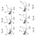
- FIGS. 3a to 3f show the operation of the unloading 20 after FIG. 1 and FIG. 2 ,
- the formed from the baling chamber bale 18 is in the FIG. 3a still in the baling room.
- the still unloaded carrier 22 extends approximately horizontally to the rear. If the bale is ejected from the baling chamber, it comes in contact with the carrier 22 (FIG. FIG. 3b ), which is bent down by the bale 18, and gradually rolls down on the flexing support 20 ( FIGS. 3c to 3e ). After the bale 18 is completely rolled from the unloading ramp 20 ( FIG. 3f ), the unloading ramp 20 springs back upwards.
- the Abladerampe 20 By making the Abladerampe 20 in itself elastic, resilient material, it is relatively lightweight and inexpensive to produce. Due to its elasticity, it adapts to the shape of the floor and the bale, which has undesirable effects on the wrapping material and avoids tensions and fatigue in the material of the unloading ramp. In addition, hardly any damage to the unloading 20 are to be feared if they should encounter when backing up against an obstacle. On the rolling surface 28 could still be a coating of rubber, steel, plastic, etc. are mounted on the support 20 to avoid damage to the wrapping material when rolling the bale 18.
Landscapes
- Life Sciences & Earth Sciences (AREA)
- Environmental Sciences (AREA)
- Engineering & Computer Science (AREA)
- Transportation (AREA)
- Mechanical Engineering (AREA)
- Storage Of Harvested Produce (AREA)
Abstract
Description
- Die Erfindung betrifft eine Abladerampe für eine Rundballenpresse, mit einem langgestreckten Träger, der einen Endes an der Rundballenpresse anbringbar oder angebracht ist und an dessen Oberseite sich eine Abrollfläche für einen aus der Rundballenpresse ausgeworfenen Ballen befindet sowie eine Rundballenpresse.
- Rundballenpressen finden Verwendung, um aus halmförmigem landwirtschaftlichem Erntegut Ballen herzustellen. Derartige Rundballenpressen weisen einen Ballenpressraum und zugehörige Pressmittel auf. Nach der Fertigstellung und ggf. Umwicklung eines Ballens mit Netz, Garn oder einer Folie wird dieser nach hinten aus dem Ballenpressraum ausgeworfen. Der Ballen rollt dann auf einer Abladerampe aus dem Ballenpressraum nach unten auf den Erdboden.
- Gebräuchliche Abladerampen umfassen einen langgestreckten, als Schweißzusammenbau ausgeführten Träger, der am Gehäuse oder Fahrwerk der Rundballenpresse um eine horizontale, quer zur Vorwärtsrichtung der Rundballenpresse verlaufende Achse schwenkbar angelenkt und durch Federkraft nach oben vorgespannt ist (vgl.
DE 102 54 954 A1 oderEP 0 288 600 A1 ). Wird der Ballen ausgeworfen, bewegt sich der Träger gegen die Kraft der Feder nach unten. Zusätzlich sind vielfach noch Schwingungsdämpfer vorgesehen, um die Schwingungen der Abladerampe beim Aufprall auf dem Boden oder nach der Rückkehr in die obere Ruheposition nach der Ballenabgabe zu dämpfen. - Die bisherigen, in sich starren Abladerampen sind relativ (kosten-) aufwändig und schwer. Außerdem besteht das Risiko, dass die Abladerampe und ggf. andere Komponenten der Ballenpresse beschädigt werden können, wenn die Abladerampe in ihrer Ruheposition beispielsweise beim Rückwärtsfahren gegen ein Hindernis stößt. Weiterhin ist die Kontaktfläche zwischen einem nicht-zylindrischen (tonnenförmigen) Ballen und der Abladerampe relativ gering, was zu hohen lokalen Auflagekräften des Ballens auf der Abladerampe führt, die wiederum zu Beschädigungen des Wickelmaterials und zum partiellen oder totalen Auflösen des Ballens führen können. Schließlich kann der Fall auftreten, dass die starre Abladerampe bei unebenem Boden nur an wenigen Stellen in Bodenberührung kommt, was zu Spannungen in der Abladerampe führt, die Materialermüdung zur Folge haben können.
- Das der Erfindung zu Grunde liegende Problem wird darin gesehen, eine Abladerampe für eine Rundballenpresse und eine Rundballenpresse bereitzustellen, bei der die erwähnten Nachteile nicht oder in einem verminderten Maß vorliegen.
- Die vorliegende Erfindung wird durch die Patentansprüche definiert.
- Eine Abladerampe für eine Rundballenpresse umfasst oder besteht aus einem langgestreckten, federnden Träger, der einen Endes an der Rundballenpresse anbringbar oder angebracht ist und der konfiguriert ist, über seine Länge als Abrollfläche für einen aus der Rundballenpresse ausgeworfenen Ballen auf den Erdboden zu dienen.
- Mit anderen Worten werden die Funktionen der bisherigen Feder, der bisherigen Schwenklagerung und des bisherigen Trägers in einem in sich federnden Träger vereint. Die federnde Flexibilität des Trägers ermöglicht es, dass dieser die Energie des Ballens beim Abrollen teilweise absorbiert, um die Rotations- und Translationsgeschwindigkeit des Ballens zu vermindern, mit welcher dieser den Erdboden erreicht. Auf diese Weise erspart man sich eine separate Feder zur Vorspannung des Trägers und erreicht, dass die Abladerampe relativ leicht und kostengünstig herstellbar ist, gegen Beschädigungen unempfindlich, da nachgiebig, ist und sich an nicht-zylindrische Ballen und/oder unebenen Boden flexibel anpasst.
- Insbesondere kann der Träger aus einem in sich federnden Material bestehen. Bei dem in sich federnden Material kann es sich um Federstahl, Kunststoff oder Gummi handeln. Es wäre jedoch auch denkbar, dass nur Anteile des Trägers aus in sich federndem Material sind und zwischen in sich starren Anteilen des Trägers angeordnet sind. Beide Anteile können makroskopisch oder mikroskopisch sein. In beiden Fällen können beispielsweise Federn aus Stahl, Gummi etc. zwischen starren Teilen aus Metall oder Kunststoff etc. eingefügt oder eingebettet werden.
- Der Träger kann einstückig sein oder mehrere seitlich nebeneinander angeordnete Elemente umfassen.
- Das federnde Material ist vorzugsweise starr am Fahrgestell oder einer Achse der Ballenpresse befestigt nach oben hin vorgespannt und erstreckt sich in der unbelasteten Ruhestellung etwa horizontal. Bei Belastung durch den Ballen erreicht das freie (rückwärtige) Ende des Trägers den Erdboden.
- Das (in sich federnde) Material des Trägers kann auf der Seite der Rundballenpresse C-förmig sein, wobei der untere Schenkel des C mit der Rundballenpresse verbindbar oder verbunden ist und der obere Schenkel des C in die Abrollfläche übergeht. Auch kann das (in sich federnde) Material des Trägers ballenabgabeseitig C-förmig sein, wobei der untere Schenkel des C beim Abladen des Ballens in Bodeneingriff gerät und der obere Schenkel des C in die Abrollfläche übergeht.
- In den Zeichnungen sind zwei nachfolgend näher beschriebene Ausführungsbeispiele der Erfindung dargestellt, wobei die Bezugszeichen nicht zu einer einschränkenden Auslegung der Ansprüche herangezogen werden sollen. Es zeigt:
- Fig. 1
- eine schematische rückwärtige Ansicht einer Rundballenpresse mit einer ersten Ausführungsform einer Abladerampe,
- Fig. 2
- eine schematische rückwärtige Ansicht einer Rundballenpresse mit einer zweiten Ausführungsform einer Abladerampe, und
- Fig. 3a bis 3f
- seitliche Ansichten der Rundballenpresse mit der Abladerampe in unterschiedlichen Phasen beim Entladen eines Ballens.
- Die
Figur 1 zeigt eine schematische perspektivische Ansicht einer Rundballenpresse 10 von rechts hinten. Zur Veranschaulichung sind einige Komponenten der Rundballenpresse 10 weggelassen worden, wie ein Gehäuse, eine Anzahl von Presswalzen und eine rückwärtige Tür. Die Rundballenpresse 10 umfasst ein Fahrgestell mit einer Achse 12, an der Räder 14 befestigt sind. Am Fahrgestell ist auch eine Anzahl an Presswalzen 16 abgestützt, die einen Ballenpressraum umschließen. Ein im Ballenpressraum gebildeter Ballen ist mit 18 gekennzeichnet. Derartige Rundballenpressen 10 sind an sich bekannt, wozu auf den eingangs erwähnten Stand der Technik verwiesen sei. Die Rundballenpresse 10 kann von beliebiger Bauart sein, z.B. mit einem Ballenpressraum fester oder variabler Größe, der von Riemen oder Ketten oder den gezeigten Presswalzen 16 umschlossen sein kann. Der Ballenpressraum kann nach hinten durch eine aufklappbare Tür verschließbar sein oder einen Schwenkteil umfassen, welcher Mittel zur Bildung eines Ballens im Ballenpressraum trägt und zwischen einer Ballenbildungsposition und einer Ballenauswurfposition drehbeweglich ist (s.EP 1 364 574 A1 ). - An der Achse 12 (oder einem anderen Teil des Fahrgestells der Rundballenpresse 10) ist eine Abladerampe 20 starr (d.h. nicht schwenkbar o.ä.) befestigt, die aus einem langgestreckten Träger 22 besteht. Der Träger 22 besteht aus in sich elastischem, federnden Material, beispielsweise Federstahl. Der Träger 22 umfasst eine langgestreckte, sich von der Achse 12 nach hinten bis zum rückwärtigen Ende des Trägers 22 erstreckende Abrollfläche 28, auf welcher der Ballen 18 nach seiner Fertigstellung und ggf. Umwicklung mit Garn, Folie oder Netz nach unten auf den Erdboden abrollt.
- An seinem in Vorwärtsrichtung der Ballenpresse 10, die in der
Figur 1 nach links vorn verläuft, vorderen Ende ist der Träger 22 C-förmig gestaltet. Der untere Schenkel 24 des C liegt von unten her an der Achse 12 an und ist damit verbunden, z.B. verschraubt. Der vordere Schenkel 22 des C erstreckt sich vom unteren Schenkel 24 etwa vertikal nach oben und der obere Schenkel des C geht in die Abrollfläche 28 über. - Auch an seinem rückwärtigen Ende ist der Träger 22 C-förmig gestaltet. Ein oberer Schenkel des C geht in die Abrollfläche 28 über, ein vertikaler Schenkel 26 des C erstreckt sich nach unten und ein unterer Schenkel 30 des C erstreckt sich nach vorn und kommt, wenn der Ballen 18 auf der Abladerampe 20 herunterrollt, in Bodenkontakt. In der unbelasteten Stellung erstreckt sich die Abrollfläche 28 von der Achse 12 etwa horizontal nach hinten.
- Bei der Ausführungsform nach
Figur 2 ist der Träger 22 aus mehreren, seitlich nebeneinander angebrachten Elementen aufgebaut, ansonsten in Aufbau und Funktion mit der Ausführungsform nachFigur 1 identisch. Die Elemente sind rechteckigen Querschnitts, der jedoch auch quadratisch oder kreisförmig sein könnte. - Die
Figuren 3a bis 3f zeigen die Funktionsweise der Abladerampe 20 nachFigur 1 undFigur 2 . Der aus dem Ballenpressraum gebildete Ballen 18 ist in derFigur 3a noch im Ballenpressraum. Der noch unbelastete Träger 22 erstreckt sich etwa horizontal nach hinten. Wird der Ballen aus dem Ballenpressraum ausgeworfen, gerät er in Auflage auf dem Träger 22 (Figur 3b ), der durch den Ballen 18 nach unten gebogen wird, und rollt nach und nach auf dem sich flexibel durchbiegenden Träger 20 nach unten (Figuren 3c bis 3e ). Nachdem der Ballen 18 komplett von der Abladerampe 20 gerollt ist (Figur 3f ), federt die Abladerampe 20 wieder nach oben. - Durch die Herstellung der Abladerampe 20 aus in sich elastischem, federnden Material ist sie relativ leichtgewichtige und preiswert herstellbar. Sie passt sich aufgrund ihrer Elastizität der Form des Bodens und des Ballens an, was ungewünschte Einwirkungen auf das Wickelmaterial und Spannungen und Ermüdungserscheinungen im Material der Abladerampe vermeidet. Zudem sind kaum Beschädigungen der Abladerampe 20 zu befürchten, wenn diese beim Rückwärtsfahren gegen ein Hindernis stoßen sollte. An der Abrollfläche 28 könnte noch eine Beschichtung aus Gummi, Stahl, Kunststoff etc. auf dem Träger 20 angebracht werden, um Beschädigungen des Wickelmaterials beim Abrollen des Ballens 18 zu vermeiden.
Claims (8)
- Abladerampe (20) für eine Rundballenpresse (10), mit einem langgestreckten Träger (22), der einen Endes an der Rundballenpresse (10) anbringbar oder angebracht ist und an dessen Oberseite sich eine Abrollfläche (28) für einen aus der Rundballenpresse (10) ausgeworfenen Ballen (18) befindet, dadurch gekennzeichnet, dass der Träger (22) in sich federnd ist.
- Abladerampe (20) nach Anspruch 1, wobei der Träger (22) aus in sich federndem Material besteht oder in sich federndes Material umfasst.
- Abladerampe (20) nach Anspruch 1 oder 2, wobei der Träger (22) einstückig ist.
- Abladerampe (20) nach Anspruch 1 oder 2, wobei der der Träger (22) mehrere seitlich nebeneinander angeordnete Elemente umfasst.
- Abladerampe (20) nach einem der Ansprüche 1 bis 4, wobei das in sich federnde Material des Trägers (20) starr am Fahrgestell oder einer Achse (12) der Ballenpresse (10) befestigt, nach oben hin vorgespannt ist und sich in der unbelasteten Ruhestellung etwa horizontal erstreckt, während der Träger (20) bei Belastung durch den Ballen (18) mit seinem freien Ende auf dem Boden aufliegt.
- Abladerampe (20) nach Anspruch 5, wobei das in sich federnde Material des Trägers (20) auf der Seite der Rundballenpresse (10) C-förmig ist, wobei der untere Schenkel (24) des C mit der Rundballenpresse (10) verbindbar oder verbunden ist und der obere Schenkel des C in die Abrollfläche (28) übergeht.
- Abladerampe (20) nach Anspruch 5 oder 6, wobei das in sich federnde Material des Trägers (22) ballenabgabeseitig C-förmig ist, wobei der untere Schenkel (30) des C beim Abladen des Ballens (18) in Bodeneingriff gerät und der obere Schenkel des C in die Abrollfläche (28) übergeht.
- Rundballenpresse (10) mit einer Abladerampe (20) nach einem der vorhergehenden Ansprüche.
Applications Claiming Priority (1)
| Application Number | Priority Date | Filing Date | Title |
|---|---|---|---|
| DE102015210999.2A DE102015210999A1 (de) | 2015-06-16 | 2015-06-16 | Abladerampe für eine Rundballenpresse |
Publications (2)
| Publication Number | Publication Date |
|---|---|
| EP3106022A1 true EP3106022A1 (de) | 2016-12-21 |
| EP3106022B1 EP3106022B1 (de) | 2020-03-18 |
Family
ID=56087189
Family Applications (1)
| Application Number | Title | Priority Date | Filing Date |
|---|---|---|---|
| EP16171881.2A Active EP3106022B1 (de) | 2015-06-16 | 2016-05-30 | Abladerampe für eine rundballenpresse |
Country Status (3)
| Country | Link |
|---|---|
| US (1) | US10076080B2 (de) |
| EP (1) | EP3106022B1 (de) |
| DE (1) | DE102015210999A1 (de) |
Cited By (1)
| Publication number | Priority date | Publication date | Assignee | Title |
|---|---|---|---|---|
| CN112319573A (zh) * | 2020-11-09 | 2021-02-05 | 灵璧县泰顺机械有限公司 | 一种稻草打捆机用卸料装置及其转运方法 |
Families Citing this family (2)
| Publication number | Priority date | Publication date | Assignee | Title |
|---|---|---|---|---|
| CN109922656A (zh) | 2016-08-31 | 2019-06-21 | 维米尔制造公司 | 连续圆形打捆机和形成圆形草捆的改进方法 |
| CN112715172B (zh) * | 2020-12-14 | 2021-10-29 | 吉林大学 | 用于测量秸秆压后回弹的可自动移除壁面型秸秆压缩模具 |
Citations (7)
| Publication number | Priority date | Publication date | Assignee | Title |
|---|---|---|---|---|
| EP0288600A1 (de) | 1987-04-27 | 1988-11-02 | Deere & Company | Maschine zum Formen von Rundpressballen |
| EP1364574A1 (de) | 2002-05-23 | 2003-11-26 | Deere & Company | Rundballenpresse |
| DE10254954A1 (de) | 2002-11-26 | 2004-06-03 | Deere & Company, Moline | Ballenentladevorrichtung einer Rundballenpresse |
| EP1444882A2 (de) * | 2003-01-28 | 2004-08-11 | Welger Maschinenfabrik GmbH | Rundballenpresse für landwirtschaftliche Halmgüter |
| EP1832157A1 (de) * | 2006-03-10 | 2007-09-12 | Deere & Company | Steuereinrichtung |
| EP2550854A1 (de) * | 2011-07-27 | 2013-01-30 | Deere & Company | Rundballenpresse |
| EP2893799A1 (de) * | 2014-01-13 | 2015-07-15 | Deere & Company | Landwirtschaftliche Rundballenpresse und Verfahren |
Family Cites Families (7)
| Publication number | Priority date | Publication date | Assignee | Title |
|---|---|---|---|---|
| US6807901B2 (en) * | 2002-08-05 | 2004-10-26 | Vermeer Manufacturing Company | Two-stage spring loaded bale ramp |
| DE10257252A1 (de) * | 2002-12-07 | 2004-08-12 | Deere & Company, Moline | Presse, insbesondere Rundballenpresse |
| US20050217506A1 (en) * | 2004-03-30 | 2005-10-06 | Cnh America Llc | Cotton packager floor including friction reducing surface |
| US7197979B2 (en) * | 2005-06-10 | 2007-04-03 | Deere & Company | Controlled bale ejection mechanism |
| DE102006038299A1 (de) * | 2006-08-16 | 2008-02-28 | Deere & Company, Moline | Rundballenpresse |
| US20120204736A1 (en) * | 2010-12-27 | 2012-08-16 | Agco Corporation | Passive Ramp Bale Clear Indicator |
| DE102011079937A1 (de) | 2011-07-27 | 2013-01-31 | Deere & Company | Rundballenpresse |
-
2015
- 2015-06-16 DE DE102015210999.2A patent/DE102015210999A1/de not_active Withdrawn
-
2016
- 2016-05-30 EP EP16171881.2A patent/EP3106022B1/de active Active
- 2016-06-14 US US15/181,829 patent/US10076080B2/en active Active
Patent Citations (7)
| Publication number | Priority date | Publication date | Assignee | Title |
|---|---|---|---|---|
| EP0288600A1 (de) | 1987-04-27 | 1988-11-02 | Deere & Company | Maschine zum Formen von Rundpressballen |
| EP1364574A1 (de) | 2002-05-23 | 2003-11-26 | Deere & Company | Rundballenpresse |
| DE10254954A1 (de) | 2002-11-26 | 2004-06-03 | Deere & Company, Moline | Ballenentladevorrichtung einer Rundballenpresse |
| EP1444882A2 (de) * | 2003-01-28 | 2004-08-11 | Welger Maschinenfabrik GmbH | Rundballenpresse für landwirtschaftliche Halmgüter |
| EP1832157A1 (de) * | 2006-03-10 | 2007-09-12 | Deere & Company | Steuereinrichtung |
| EP2550854A1 (de) * | 2011-07-27 | 2013-01-30 | Deere & Company | Rundballenpresse |
| EP2893799A1 (de) * | 2014-01-13 | 2015-07-15 | Deere & Company | Landwirtschaftliche Rundballenpresse und Verfahren |
Cited By (2)
| Publication number | Priority date | Publication date | Assignee | Title |
|---|---|---|---|---|
| CN112319573A (zh) * | 2020-11-09 | 2021-02-05 | 灵璧县泰顺机械有限公司 | 一种稻草打捆机用卸料装置及其转运方法 |
| CN112319573B (zh) * | 2020-11-09 | 2022-01-28 | 灵璧县泰顺机械有限公司 | 一种稻草打捆机用卸料装置及其转运方法 |
Also Published As
| Publication number | Publication date |
|---|---|
| DE102015210999A1 (de) | 2016-12-22 |
| US20160366830A1 (en) | 2016-12-22 |
| EP3106022B1 (de) | 2020-03-18 |
| US10076080B2 (en) | 2018-09-18 |
Similar Documents
| Publication | Publication Date | Title |
|---|---|---|
| DE102011003727A1 (de) | Rundballenpresse mit seitlichen Führungen für den Pressriemen | |
| DE2362529A1 (de) | Lagergestell mit fachboden und anschlussecken | |
| EP3612014B1 (de) | Bodenbearbeitungsgerät | |
| DE102013004274B4 (de) | Einzugvorrichtung für eine Häckseleinrichtung eines Feldhäckslers | |
| DE202017007380U1 (de) | Schneidmesser-Überlastsicherung | |
| EP3106022B1 (de) | Abladerampe für eine rundballenpresse | |
| DE10153539A1 (de) | Rundballenpresse | |
| DE1782102A1 (de) | Fahrbare Maschine zum Aufladen und/oder Abladen von Stalldung oder pflanzlichem Gut | |
| EP1889534A1 (de) | Rundballenpresse | |
| DE10257480B4 (de) | Energieabsorbierendes Wischersystem für ein Fahrzeug | |
| DE10153540A1 (de) | Rundballenpresse | |
| EP0672597A1 (de) | Überladebrücke für Rampen | |
| EP1878474A1 (de) | Sammeleinrichtung für Tennisbälle | |
| DE202016100132U1 (de) | Rundballensammelvorrichtung und Rundballensammelfahrzeug mit einer derartigen Rundballensammelvorrichtung | |
| DE102009051191A1 (de) | Nachrüstbares Rollenelement und Fuß für ein automatisches Lagersystem sowie Verfahren zum Verschieben eines automatischen Lagersystems | |
| EP3689186A1 (de) | Rolle für apparate, möbel, mit einem ein kopfteil und ein fussteil aufweisendes tragteil | |
| EP3608213A1 (de) | Landwirtschaftliche arbeitsmaschine | |
| DE202021003314U1 (de) | Tragvorrichtung | |
| DE2443609C3 (de) | ||
| EP4289237B1 (de) | Ackerstriegel | |
| WO2020201459A1 (de) | Warenkorb | |
| DE2554352C3 (de) | Räumvorrichtung, insbesondere zum Räumen abgeholzter Forstflächen | |
| DE202008012224U1 (de) | Einzugsvorrichtung für ein Häckselaggregat eines Feldhäckslers | |
| DE102015008096B4 (de) | "Lift, insbesondere für die Beförderung von Rollstuhlfahrern" | |
| AT400791B (de) | Ladewagen für landwirtschaftliches halmgut |
Legal Events
| Date | Code | Title | Description |
|---|---|---|---|
| PUAI | Public reference made under article 153(3) epc to a published international application that has entered the european phase |
Free format text: ORIGINAL CODE: 0009012 |
|
| STAA | Information on the status of an ep patent application or granted ep patent |
Free format text: STATUS: THE APPLICATION HAS BEEN PUBLISHED |
|
| AK | Designated contracting states |
Kind code of ref document: A1 Designated state(s): AL AT BE BG CH CY CZ DE DK EE ES FI FR GB GR HR HU IE IS IT LI LT LU LV MC MK MT NL NO PL PT RO RS SE SI SK SM TR |
|
| AX | Request for extension of the european patent |
Extension state: BA ME |
|
| STAA | Information on the status of an ep patent application or granted ep patent |
Free format text: STATUS: REQUEST FOR EXAMINATION WAS MADE |
|
| 17P | Request for examination filed |
Effective date: 20170621 |
|
| RBV | Designated contracting states (corrected) |
Designated state(s): AL AT BE BG CH CY CZ DE DK EE ES FI FR GB GR HR HU IE IS IT LI LT LU LV MC MK MT NL NO PL PT RO RS SE SI SK SM TR |
|
| RIC1 | Information provided on ipc code assigned before grant |
Ipc: A01F 15/08 20060101AFI20190808BHEP |
|
| GRAP | Despatch of communication of intention to grant a patent |
Free format text: ORIGINAL CODE: EPIDOSNIGR1 |
|
| STAA | Information on the status of an ep patent application or granted ep patent |
Free format text: STATUS: GRANT OF PATENT IS INTENDED |
|
| INTG | Intention to grant announced |
Effective date: 20191015 |
|
| GRAS | Grant fee paid |
Free format text: ORIGINAL CODE: EPIDOSNIGR3 |
|
| GRAA | (expected) grant |
Free format text: ORIGINAL CODE: 0009210 |
|
| STAA | Information on the status of an ep patent application or granted ep patent |
Free format text: STATUS: THE PATENT HAS BEEN GRANTED |
|
| AK | Designated contracting states |
Kind code of ref document: B1 Designated state(s): AL AT BE BG CH CY CZ DE DK EE ES FI FR GB GR HR HU IE IS IT LI LT LU LV MC MK MT NL NO PL PT RO RS SE SI SK SM TR |
|
| REG | Reference to a national code |
Ref country code: GB Ref legal event code: FG4D Free format text: NOT ENGLISH |
|
| REG | Reference to a national code |
Ref country code: DE Ref legal event code: R096 Ref document number: 502016009171 Country of ref document: DE |
|
| REG | Reference to a national code |
Ref country code: AT Ref legal event code: REF Ref document number: 1244832 Country of ref document: AT Kind code of ref document: T Effective date: 20200415 Ref country code: IE Ref legal event code: FG4D Free format text: LANGUAGE OF EP DOCUMENT: GERMAN |
|
| PG25 | Lapsed in a contracting state [announced via postgrant information from national office to epo] |
Ref country code: NO Free format text: LAPSE BECAUSE OF FAILURE TO SUBMIT A TRANSLATION OF THE DESCRIPTION OR TO PAY THE FEE WITHIN THE PRESCRIBED TIME-LIMIT Effective date: 20200618 Ref country code: RS Free format text: LAPSE BECAUSE OF FAILURE TO SUBMIT A TRANSLATION OF THE DESCRIPTION OR TO PAY THE FEE WITHIN THE PRESCRIBED TIME-LIMIT Effective date: 20200318 Ref country code: FI Free format text: LAPSE BECAUSE OF FAILURE TO SUBMIT A TRANSLATION OF THE DESCRIPTION OR TO PAY THE FEE WITHIN THE PRESCRIBED TIME-LIMIT Effective date: 20200318 |
|
| REG | Reference to a national code |
Ref country code: NL Ref legal event code: MP Effective date: 20200318 |
|
| PG25 | Lapsed in a contracting state [announced via postgrant information from national office to epo] |
Ref country code: HR Free format text: LAPSE BECAUSE OF FAILURE TO SUBMIT A TRANSLATION OF THE DESCRIPTION OR TO PAY THE FEE WITHIN THE PRESCRIBED TIME-LIMIT Effective date: 20200318 Ref country code: GR Free format text: LAPSE BECAUSE OF FAILURE TO SUBMIT A TRANSLATION OF THE DESCRIPTION OR TO PAY THE FEE WITHIN THE PRESCRIBED TIME-LIMIT Effective date: 20200619 Ref country code: SE Free format text: LAPSE BECAUSE OF FAILURE TO SUBMIT A TRANSLATION OF THE DESCRIPTION OR TO PAY THE FEE WITHIN THE PRESCRIBED TIME-LIMIT Effective date: 20200318 Ref country code: LV Free format text: LAPSE BECAUSE OF FAILURE TO SUBMIT A TRANSLATION OF THE DESCRIPTION OR TO PAY THE FEE WITHIN THE PRESCRIBED TIME-LIMIT Effective date: 20200318 Ref country code: BG Free format text: LAPSE BECAUSE OF FAILURE TO SUBMIT A TRANSLATION OF THE DESCRIPTION OR TO PAY THE FEE WITHIN THE PRESCRIBED TIME-LIMIT Effective date: 20200618 |
|
| REG | Reference to a national code |
Ref country code: LT Ref legal event code: MG4D |
|
| PG25 | Lapsed in a contracting state [announced via postgrant information from national office to epo] |
Ref country code: NL Free format text: LAPSE BECAUSE OF FAILURE TO SUBMIT A TRANSLATION OF THE DESCRIPTION OR TO PAY THE FEE WITHIN THE PRESCRIBED TIME-LIMIT Effective date: 20200318 |
|
| PG25 | Lapsed in a contracting state [announced via postgrant information from national office to epo] |
Ref country code: EE Free format text: LAPSE BECAUSE OF FAILURE TO SUBMIT A TRANSLATION OF THE DESCRIPTION OR TO PAY THE FEE WITHIN THE PRESCRIBED TIME-LIMIT Effective date: 20200318 Ref country code: LT Free format text: LAPSE BECAUSE OF FAILURE TO SUBMIT A TRANSLATION OF THE DESCRIPTION OR TO PAY THE FEE WITHIN THE PRESCRIBED TIME-LIMIT Effective date: 20200318 Ref country code: SM Free format text: LAPSE BECAUSE OF FAILURE TO SUBMIT A TRANSLATION OF THE DESCRIPTION OR TO PAY THE FEE WITHIN THE PRESCRIBED TIME-LIMIT Effective date: 20200318 Ref country code: RO Free format text: LAPSE BECAUSE OF FAILURE TO SUBMIT A TRANSLATION OF THE DESCRIPTION OR TO PAY THE FEE WITHIN THE PRESCRIBED TIME-LIMIT Effective date: 20200318 Ref country code: PT Free format text: LAPSE BECAUSE OF FAILURE TO SUBMIT A TRANSLATION OF THE DESCRIPTION OR TO PAY THE FEE WITHIN THE PRESCRIBED TIME-LIMIT Effective date: 20200812 Ref country code: CZ Free format text: LAPSE BECAUSE OF FAILURE TO SUBMIT A TRANSLATION OF THE DESCRIPTION OR TO PAY THE FEE WITHIN THE PRESCRIBED TIME-LIMIT Effective date: 20200318 Ref country code: SK Free format text: LAPSE BECAUSE OF FAILURE TO SUBMIT A TRANSLATION OF THE DESCRIPTION OR TO PAY THE FEE WITHIN THE PRESCRIBED TIME-LIMIT Effective date: 20200318 Ref country code: IS Free format text: LAPSE BECAUSE OF FAILURE TO SUBMIT A TRANSLATION OF THE DESCRIPTION OR TO PAY THE FEE WITHIN THE PRESCRIBED TIME-LIMIT Effective date: 20200718 |
|
| REG | Reference to a national code |
Ref country code: DE Ref legal event code: R097 Ref document number: 502016009171 Country of ref document: DE |
|
| PLBE | No opposition filed within time limit |
Free format text: ORIGINAL CODE: 0009261 |
|
| STAA | Information on the status of an ep patent application or granted ep patent |
Free format text: STATUS: NO OPPOSITION FILED WITHIN TIME LIMIT |
|
| PG25 | Lapsed in a contracting state [announced via postgrant information from national office to epo] |
Ref country code: LI Free format text: LAPSE BECAUSE OF NON-PAYMENT OF DUE FEES Effective date: 20200531 Ref country code: ES Free format text: LAPSE BECAUSE OF FAILURE TO SUBMIT A TRANSLATION OF THE DESCRIPTION OR TO PAY THE FEE WITHIN THE PRESCRIBED TIME-LIMIT Effective date: 20200318 Ref country code: CH Free format text: LAPSE BECAUSE OF NON-PAYMENT OF DUE FEES Effective date: 20200531 Ref country code: DK Free format text: LAPSE BECAUSE OF FAILURE TO SUBMIT A TRANSLATION OF THE DESCRIPTION OR TO PAY THE FEE WITHIN THE PRESCRIBED TIME-LIMIT Effective date: 20200318 Ref country code: MC Free format text: LAPSE BECAUSE OF FAILURE TO SUBMIT A TRANSLATION OF THE DESCRIPTION OR TO PAY THE FEE WITHIN THE PRESCRIBED TIME-LIMIT Effective date: 20200318 Ref country code: IT Free format text: LAPSE BECAUSE OF FAILURE TO SUBMIT A TRANSLATION OF THE DESCRIPTION OR TO PAY THE FEE WITHIN THE PRESCRIBED TIME-LIMIT Effective date: 20200318 |
|
| 26N | No opposition filed |
Effective date: 20201221 |
|
| PG25 | Lapsed in a contracting state [announced via postgrant information from national office to epo] |
Ref country code: PL Free format text: LAPSE BECAUSE OF FAILURE TO SUBMIT A TRANSLATION OF THE DESCRIPTION OR TO PAY THE FEE WITHIN THE PRESCRIBED TIME-LIMIT Effective date: 20200318 |
|
| REG | Reference to a national code |
Ref country code: BE Ref legal event code: MM Effective date: 20200531 |
|
| GBPC | Gb: european patent ceased through non-payment of renewal fee |
Effective date: 20200618 |
|
| PG25 | Lapsed in a contracting state [announced via postgrant information from national office to epo] |
Ref country code: LU Free format text: LAPSE BECAUSE OF NON-PAYMENT OF DUE FEES Effective date: 20200530 |
|
| PG25 | Lapsed in a contracting state [announced via postgrant information from national office to epo] |
Ref country code: IE Free format text: LAPSE BECAUSE OF NON-PAYMENT OF DUE FEES Effective date: 20200530 Ref country code: GB Free format text: LAPSE BECAUSE OF NON-PAYMENT OF DUE FEES Effective date: 20200618 |
|
| PG25 | Lapsed in a contracting state [announced via postgrant information from national office to epo] |
Ref country code: SI Free format text: LAPSE BECAUSE OF FAILURE TO SUBMIT A TRANSLATION OF THE DESCRIPTION OR TO PAY THE FEE WITHIN THE PRESCRIBED TIME-LIMIT Effective date: 20200318 Ref country code: BE Free format text: LAPSE BECAUSE OF NON-PAYMENT OF DUE FEES Effective date: 20200531 |
|
| PG25 | Lapsed in a contracting state [announced via postgrant information from national office to epo] |
Ref country code: TR Free format text: LAPSE BECAUSE OF FAILURE TO SUBMIT A TRANSLATION OF THE DESCRIPTION OR TO PAY THE FEE WITHIN THE PRESCRIBED TIME-LIMIT Effective date: 20200318 Ref country code: MT Free format text: LAPSE BECAUSE OF FAILURE TO SUBMIT A TRANSLATION OF THE DESCRIPTION OR TO PAY THE FEE WITHIN THE PRESCRIBED TIME-LIMIT Effective date: 20200318 Ref country code: CY Free format text: LAPSE BECAUSE OF FAILURE TO SUBMIT A TRANSLATION OF THE DESCRIPTION OR TO PAY THE FEE WITHIN THE PRESCRIBED TIME-LIMIT Effective date: 20200318 |
|
| PG25 | Lapsed in a contracting state [announced via postgrant information from national office to epo] |
Ref country code: MK Free format text: LAPSE BECAUSE OF FAILURE TO SUBMIT A TRANSLATION OF THE DESCRIPTION OR TO PAY THE FEE WITHIN THE PRESCRIBED TIME-LIMIT Effective date: 20200318 Ref country code: AL Free format text: LAPSE BECAUSE OF FAILURE TO SUBMIT A TRANSLATION OF THE DESCRIPTION OR TO PAY THE FEE WITHIN THE PRESCRIBED TIME-LIMIT Effective date: 20200318 |
|
| REG | Reference to a national code |
Ref country code: AT Ref legal event code: MM01 Ref document number: 1244832 Country of ref document: AT Kind code of ref document: T Effective date: 20210530 |
|
| PG25 | Lapsed in a contracting state [announced via postgrant information from national office to epo] |
Ref country code: AT Free format text: LAPSE BECAUSE OF NON-PAYMENT OF DUE FEES Effective date: 20210530 |
|
| PGFP | Annual fee paid to national office [announced via postgrant information from national office to epo] |
Ref country code: DE Payment date: 20250423 Year of fee payment: 10 |
|
| PGFP | Annual fee paid to national office [announced via postgrant information from national office to epo] |
Ref country code: FR Payment date: 20250526 Year of fee payment: 10 |