EP3105165B1 - Hebezeug mit hysteresekupplung - Google Patents
Hebezeug mit hysteresekupplung Download PDFInfo
- Publication number
- EP3105165B1 EP3105165B1 EP15703091.7A EP15703091A EP3105165B1 EP 3105165 B1 EP3105165 B1 EP 3105165B1 EP 15703091 A EP15703091 A EP 15703091A EP 3105165 B1 EP3105165 B1 EP 3105165B1
- Authority
- EP
- European Patent Office
- Prior art keywords
- torque
- lifting gear
- clutch
- load
- hysteresis clutch
- Prior art date
- Legal status (The legal status is an assumption and is not a legal conclusion. Google has not performed a legal analysis and makes no representation as to the accuracy of the status listed.)
- Active
Links
Images


Classifications
-
- B—PERFORMING OPERATIONS; TRANSPORTING
- B66—HOISTING; LIFTING; HAULING
- B66D—CAPSTANS; WINCHES; TACKLES, e.g. PULLEY BLOCKS; HOISTS
- B66D1/00—Rope, cable, or chain winding mechanisms; Capstans
- B66D1/54—Safety gear
- B66D1/58—Safety gear responsive to excess of load
-
- B—PERFORMING OPERATIONS; TRANSPORTING
- B66—HOISTING; LIFTING; HAULING
- B66D—CAPSTANS; WINCHES; TACKLES, e.g. PULLEY BLOCKS; HOISTS
- B66D1/00—Rope, cable, or chain winding mechanisms; Capstans
- B66D1/02—Driving gear
- B66D1/14—Power transmissions between power sources and drums or barrels
-
- B—PERFORMING OPERATIONS; TRANSPORTING
- B66—HOISTING; LIFTING; HAULING
- B66D—CAPSTANS; WINCHES; TACKLES, e.g. PULLEY BLOCKS; HOISTS
- B66D3/00—Portable or mobile lifting or hauling appliances
- B66D3/18—Power-operated hoists
- B66D3/20—Power-operated hoists with driving motor, e.g. electric motor, and drum or barrel contained in a common housing
- B66D3/22—Power-operated hoists with driving motor, e.g. electric motor, and drum or barrel contained in a common housing with variable-speed gearings between driving motor and drum or barrel
-
- H—ELECTRICITY
- H02—GENERATION; CONVERSION OR DISTRIBUTION OF ELECTRIC POWER
- H02K—DYNAMO-ELECTRIC MACHINES
- H02K49/00—Dynamo-electric clutches; Dynamo-electric brakes
- H02K49/06—Dynamo-electric clutches; Dynamo-electric brakes of the synchronous type
- H02K49/065—Dynamo-electric clutches; Dynamo-electric brakes of the synchronous type hysteresis type
-
- H—ELECTRICITY
- H02—GENERATION; CONVERSION OR DISTRIBUTION OF ELECTRIC POWER
- H02K—DYNAMO-ELECTRIC MACHINES
- H02K7/00—Arrangements for handling mechanical energy structurally associated with dynamo-electric machines, e.g. structural association with mechanical driving motors or auxiliary dynamo-electric machines
- H02K7/10—Structural association with clutches, brakes, gears, pulleys or mechanical starters
- H02K7/11—Structural association with clutches, brakes, gears, pulleys or mechanical starters with dynamo-electric clutches
-
- H—ELECTRICITY
- H02—GENERATION; CONVERSION OR DISTRIBUTION OF ELECTRIC POWER
- H02K—DYNAMO-ELECTRIC MACHINES
- H02K7/00—Arrangements for handling mechanical energy structurally associated with dynamo-electric machines, e.g. structural association with mechanical driving motors or auxiliary dynamo-electric machines
- H02K7/10—Structural association with clutches, brakes, gears, pulleys or mechanical starters
- H02K7/116—Structural association with clutches, brakes, gears, pulleys or mechanical starters with gears
Definitions
- the invention relates to a hoist, the drive train of which has a hysteresis clutch.
- Hoists are used to lift loads using chains, ropes or other traction equipment.
- a motor is used to drive the same, with a gear being arranged between the traction means and the motor.
- U.S. 3,573,518 proposes a hoist whose drive train, consisting of a motor and gears, has a hysteresis clutch. This is housed in its own housing, which is arranged as an extension of the motor housing.
- the hysteresis clutch is driven by the motor shaft and is in turn connected to the input shaft of the gearbox.
- the hysteresis clutch comprises a motor-driven rotor provided with permanent magnets and a disk of hysteresis-affected magnetizable material arranged at a small distance from it. A disc-shaped air gap results.
- the disc is also electrically conductive to generate slip-induced eddy currents.
- a thermal switch connected to the disc is used to shut down the drive if slippage occurring at the hysteresis clutch does not disappear after a short time.
- the hysteresis clutch is tuned in such a way that it only allows slip in the event of an overload and otherwise causes a non-rotatable coupling between the two halves of the clutch.
- the clutch is only effective unidirectionally in the up direction.
- the effect of the hysteresis clutch is prevented by a one-way clutch which is arranged in parallel with the hysteresis clutch.
- the overrunning clutch is used to overcome the braking torque of a load pressure brake when lowering the load. The engine starting torque required for this is greater than the torque required to raise the rated load.
- the hoist according to the invention has a limit torque at which the hysteresis clutch begins to slip without mechanical friction.
- the slip torque is lower than the rated load torque.
- the rated load torque is the torque that occurs at the coupling when the hoist lifts the rated load, ie the load for which it is maximum approved.
- the slip is the speed difference between the clutch halves divided by the speed of the motor-driven clutch half. The slip that occurs before the rated load is reached improves the operation of the hoist in several aspects and in several situations: When lifting a load, in particular when lifting at high lifting speeds, a chain or a corresponding cable coupled to a lying load is initially slack.
- the invention gives the operator feedback on the size of the load in daily practical operation. At a constant speed of the driving motor, loads that are less than the rated load but at which the limit torque is exceeded are lifted visibly more slowly than loads that are less than the limit load (at which the limit torque would be reached). The operator thus perceives that the nominal load is being approached by lifting the picked-up load much more slowly.
- a soft start of the hoist can also be achieved without inverter control of the motor.
- the g-force required to accelerate a suspended load in the lifting direction when a motor is turned on causes increased slip, allowing the load to accelerate more slowly than the motor. This This also applies to speed changes, where the motor changes its speed very quickly and temporarily increased slip in the hysteresis clutch allows reduced acceleration of the load and thus a reduction in the acting forces.
- a similar behavior can also be achieved when the engine is switched off.
- the hysteresis clutch allows vibrations to be efficiently absorbed, in particular due to its damping effect, which is independent of the direction of rotation. Such vibrations are stimulated by switching the motor on and off, by changing the speed or by the polygon effect in chain hoists (excitation of vibrations in the tensioned chain as a result of changing radii on the sprocket). In this way it can be prevented that the nominal load is exceeded due to resonant chain vibration and that a shutdown or other countermeasures therefore have to be taken.
- the limit torque at which the hysteresis clutch begins to develop non-zero slip may suitably be set, for example, at a maximum of 0.95 times, 0.9 times, 0.8 times or some other ratio of the rated load torque.
- the hysteresis clutch preferably has an increasing transmitted torque with increasing slip. This ensures that torques above the limit torque can be transmitted.
- the hysteresis clutch can thus allow lifting of loads slightly larger than the rated load.
- the slip can be as high as 1 (i.e. 100%).
- the force generated by the hoist at slip 1 is preferably within a tolerance range of forces that do not yet result in damage to the hoist or its supporting structures.
- the hysteresis clutch is designed to allow prolonged high-slip operation without causing the engine to shut down.
- the hysteresis clutch provides passive protection for the hoist and its support structure, and the hysteresis clutch can be used to limit the force when dimensioning them. This makes it possible to reduce the safety margins that would otherwise have to be taken when dimensioning the system, without having to accept a reduction in safety.
- the hysteresis clutch can be connected to a speed detection means.
- the rotational speed detection means can be designed as an absolute encoder or as an incremental encoder.
- the rotational speed detection means is preferably associated with at least the output-side clutch half in order to monitor its rotational speed.
- a further speed detection means can detect and monitor the speed of the input-side clutch half. This speed detection means can also be built into the engine. Speed detection means of each of the types mentioned above are always collectively referred to below as “speed sensors”.
- An evaluation device can be used by the speed sensors compare the detected speeds and in particular determine the speed difference.
- the speed difference engine-side clutch speed minus transmission-side clutch speed
- the torque/slip characteristic preferably increases linearly. Above the limit torque, the detected slip can serve as a measure of the force applied by the hoist. This also applies to non-linear torque/slip relationships.
- the hysteresis clutch is arranged in an oil bath.
- This oil bath can be part of the gearbox oil fill or a separate volume of oil.
- the hysteresis clutch can be arranged in the transmission housing. In both cases, the oil bath can be used efficiently to cool the hysteresis clutch by absorbing the heat generated on one half of the clutch and transferring it to the housing of the hoist in order to conduct the heat to the environment.
- the hysteresis clutch can be in contact with an oil flow that is formed by the transmission oil. As a result, the power converted into heat by slip is dissipated so efficiently that continuous operation of the hoist with slip is possible.
- the hysteresis clutch is preferably constructed cylindrically, with a permanent-magnetic rotor on the inside and a hollow-cylindrical hysteresis ring on the outside, which can be subject to considerable heating during operation. Because this is arranged radially on the outside, simple and efficient cooling is possible.
- the air gap of the hysteresis clutch can be free of oil or, if necessary, also filled with oil. In the latter case, oil present in the air gap can, due to its viscosity and/or lead to additional torque transmission as a result of hydrodynamic effects. It is possible to use the reduction in oil viscosity associated with increasing heating of the oil in the air gap to reduce torque transmission in the event of permanent overload, in order to prevent the operator from further overloading the hoist.
- the hysteresis clutch preferably has an air gap with an adjustable size.
- an axial adjustment of at least one half of the clutch can be used to shorten the same axially while the radial air gap width remains the same, in order to set the limit torque as desired.
- an axial adjustment of at least one clutch half can be used to adjust the air gap both in its radial and in its axial width or length.
- the limit torque and/or the form and/or the steepness of the torque/slip characteristic can be adjusted or adjusted.
- An advantageous embodiment of the hoist has a drive train with at least one brake, wherein at least one of the brakes is arranged on the transmission side from the point of view of the hysteresis clutch. If the brake connected to the gearbox is designed for a braking torque that is at least as high as the sum of the maximum load torque and the maximum torque that can be applied by the hysteresis clutch or the motor, whichever is lower, a safety-related drive can be created become.
- the brake can hold the load even if the motor rotates uncontrolled in any direction, while the hysteresis clutch limits the transmitted torque to a value that can still be safely absorbed by the brake.
- the mechanical non-contact hysteresis clutch can reach a temperature at which one or more permanent magnets weaken or demagnetize completely. This weakens or interrupts the torque transmission. This prevents further heating and dangerous overheating of the drive. This applies to hoists with converter-controlled drives as well as for hoists with mains-controlled drives.
- the concept is also suitable for safety-related drives.
- the motor is operated via an inverter that does not meet the regulations for safety-related inverters, the desired safety can still be achieved through the combination of brake and hysteresis clutch. This applies in particular if the maximum transmissible torque, which is transmitted with a slip of 1, and the torque resulting from the nominal load can be absorbed by the brake with sufficient certainty.
- a hoist 10 is illustrated, which can be part of a crane, a crane system or the like and is used to lift loads by means of a traction device 11, for example in the form of a round link chain 12, another chain of a rope or the like.
- the chain 12 runs over a pocket wheel 13 which is connected to the output side of a drive train 14 .
- the motor 15 can be an asynchronous motor, a synchronous motor or another electric motor, a hydraulic motor, a pneumatic motor or another drive source.
- the gearbox 16 is a reduction gear that translates high engine speed into low speed of the pocket wheel 13 to raise and lower loads.
- the transmission 16 is preferably a gear transmission without self-locking. If necessary, however, it can also contain self-locking components such as a worm gear.
- a brake 17 on the transmission side is connected to the drive train 14 . It is preferably a disc brake with a brake disc 18 to which brake pads 19, 20 are assigned. These are preferably tensioned by the force of a spring 22 on the brake disk 18 . They can be released by one or more electromagnets 21 to release the brake disc 18.
- the gear 16 is how figure 2 can be seen schematically, a reduction gear, which is connected via a hysteresis clutch 23 to the motor 15.
- the hysteresis clutch 23 has an input-side clutch half 24 which is connected to the output shaft of the motor 15 and a transmission-side drive half 25 which is connected to the input shaft of the transmission 16 .
- One of the shafts of the gear 16 is connected to the brake 17 .
- the hysteresis clutch 23 preferably has a basic cylindrical design with a cylindrical air gap 26 enclosed between the clutch halves 24,25.
- At least one of the coupling halves 24, 25 can be connected to a speed sensor, in the simplest case a centrifugal switch.
- both coupling halves 24, 25 can be connected to speed sensors 27, 28, which each generate a signal corresponding to the speed of the coupling half 24 or 25, respectively.
- the signals can be switching signals, analog signals or digital signals that characterize the speed and/or the phase relationship of the clutch halves 24, 25 to one another.
- the signals can be sent to a unit 29 for speed determination, slip detection and/or slip determination.
- the slip detected in this way and/or the rotational speed(s) can (can) be used as a control criterion for the operation of the motor 15 and/or the brake 17 .
- the amount of the load can be determined from the slip.
- the hysteresis clutch 23 and the gear 16 can, as figure 2 schematically illustrated, be arranged in a common transmission housing 30 containing an oil filling.
- the oil is used to lubricate bearings and gears as well as to dissipate heat loss generated in the transmission housing 30 .
- the existing oil can be used to transfer the heat loss from the hysteresis clutch 23 to the transmission housing 30 .
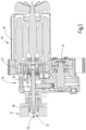
- FIG. 12 illustrates the structure of the hoist 10 with the brake 17 on the transmission side in a less abstract manner using the same reference numerals.
- the hoist 10 has an adjusting device 31 for adjusting the hysteresis clutch 23 .
- the adjusting device 31 comprises an adjusting screw 32 on which a shaft 33 connected to the clutch half 25 on the transmission side is supported. By adjusting the axial position of the shaft 33, the axial relative position of the coupling halves 24, 25 to each other and thus the size of the air gap 26 is adjusted.
- the hoist 10 described so far works as follows:
- the hoist 10 can be used to move loads (lift or pull diagonally or horizontally) that are connected to the traction device 11 . This can be done at the free end of the traction device 11 or via a loose pulley arranged in a hook block if the free end of the traction device 11 is attached to a fixed suspension point, for example to the gear housing 30 .
- the motor 15 rotates, it transmits the driving torque via the hysteresis clutch 23 and the gear 16 to the pocket wheel 13 or another winding wheel in order to lift or otherwise move the load. If the weight of the load is less than a limit force F 0 , this can be done without the hysteresis clutch 23 slipping significantly.
- a limit torque on the hysteresis clutch 23 corresponds to the limit force F 0 M 0 .
- the hysteresis clutch 23 preferably has a linear characteristic curve 34, ie the transmitted torque M increases with increasing slip s.
- the nominal slip s Nom is between 0 and 1. It can be greater than 5% or 10%, for example. It is preferably selected in such a way that the rated load can still be raised quickly, but at a significantly reduced speed, in order to signal to the operator that the rated load has been reached.
- gear reduction can be reduced, i.e. set so that the desired higher speed is reached despite slip.
- the advantage of such a gear ratio selection is that partial loads can be moved more quickly, thereby increasing work efficiency.
- the torque/slip characteristic does not necessarily have to be linear. She can also, as in figure 4 indicated as a torque/slip characteristic curve 35, deviate from the straight line shape, so that at limit loads that are less than half the nominal load F Nom , a slip that differs from 0 already occurs.
- Such characteristic curves are preferably degressive, however, in order to generate a maximum force F Max for a slip equal to 1, ie when the traction mechanism 11 is blocked, which is limited to a safe value and is for example 1.5 times, preferably 1.3 times, more preferably at most 1.2 times, more preferably at most 1.1 times the nominal load F Nom or a value between the mentioned values value of the nominal load.
- the maximum torque M Max occurs at the hysteresis clutch 23 .
- the slip is determined and the operating state of the hoist 10 is concluded or influenced. For example, it is possible to lower the speed of the motor 15 when the nominal slip s Nom is exceeded, in order to thereby prevent the lifting of loads that are greater than the nominal load F Nom , but without completely switching off the motor 15 in the process.
- figure 5 illustrates the switching on of a motor 15 that can be operated at two speeds N 1 , N 2 .
- Curve 36 shows the course of the motor speed and thus the speed of clutch half 24.
- Curve 37 shows the course of the speed of clutch half 25.
- the load decreases the slip s increases briefly, so that the speed of the transmission-side clutch half 25 follows the speed of the motor 15 with a delay. In this way, an abrupt load on the traction means 11 is avoided or reduced.
- the effect is correspondingly also in the case of a motor 15 which is only to be operated at a single fixed speed.
- the hysteresis clutch 23 reaches slip 0 after a certain time, ie the load is less than the limit load F 0 .
- figure 6 shows operation with a load weight greater than the limit load F 0 . While the engine speed changes almost suddenly (curve 38), the speed follows the transmission-side clutch half 25 with a significant delay, without ever reaching the engine speed. The operation of the hoist 10 is thus particularly smooth when approaching the nominal load F Nom .
- the optional brake 17a is in figure 2 illustrated. It has a brake disc 18a, brake pads 19a, 20a, a closing spring 22a and an electromagnet 21a, which releases the brake 17a against the force of the closing spring 22a.
- two brakes 17, 17a are used, they must be controlled in such a way that first the motor-side brake 17a brakes and then—after a delay—the transmission-side brake 17 brakes.
- the engine speed 36 and 38 drops rapidly.
- the load is gently decelerated by the hysteresis clutch 23, which now acts like a hysteresis brake.
- gentle slowing down of the load is in the Figures 5 and 6 illustrated by dashed lines.
- the load is held securely by the brake 17 on the transmission side.
- the described hoist with two brakes supports the possibility of controlled lowering of the load.
- figure 7 illustrates another useful one Effect on the hoist 10.
- a torque/time diagram is given for this purpose, which characterizes the course of the torque M on the hysteresis clutch 23 in the event of an increase in vibration.
- Such an amplification of the vibration can take place through the polygon effect of the pocket wheel 13 .
- the rotating pocket wheel 13 which is polygonal in terms of effect, excites the chain 12 with a frequency which corresponds to the resonant frequency of the tensioned chain, the chain can oscillate violently. These are expressed in corresponding torque fluctuations, which can lead to damage to the drive and higher-level components, such as supporting structures.
- figure 7 Illustrates in a dashed line 40 a torque curve that results in which the nominal torque M Nom and thus also the corresponding nominal load F Nom would be exceeded.
- the torque represented by a solid line 41 at the hysteresis clutch 23 repeatedly reaches a zone between the limit torque M 0 and the nominal torque M Nom in time periods ⁇ t. In this zone, the slip s is different from 0, so that energy is withdrawn from the vibration process and converted into heat. This effectively dampens the vibration so that it comes to a complete standstill or at least the nominal torque M Nom (and thus the nominal load F Nom ) is not exceeded.
- the hoist 10 has a drive train 14 which contains a hysteresis clutch 23 .
- This transmits torque from a drive motor 15 to a gear 16 and thus drives a traction mechanism 11 .
- the hysteresis clutch 23 is set in such a way that it has a slip that is significantly different from 0 even before the rated load F Nom is reached on the traction mechanism. If the hoist is operated from or near its rated load F Nom , it will work with constant slip.
- the resulting heat loss is preferably an oil bath to the Dissipated wall of the transmission housing, which thus serves as a cooling surface.
- the hoist 10 which has been improved in this respect, permits slimmer dimensions and has improved operating properties.
- Its hysteresis clutch 23 enables it to be used as a hysteresis brake for controlled emergency lowering of the load; it acts as a vibration damper to absorb load vibrations; it can serve as a safe torque limitation in the event of an emergency stop when the load is stopped by means of the transmission-side brake 17 and continued operation of the motor 16 and/or to indicate the load to the operator by changing the load lifting speed depending on the load at a constant motor speed.
Landscapes
- Engineering & Computer Science (AREA)
- Mechanical Engineering (AREA)
- Power Engineering (AREA)
- Connection Of Motors, Electrical Generators, Mechanical Devices, And The Like (AREA)
- General Details Of Gearings (AREA)
- Hybrid Electric Vehicles (AREA)
- Control Of Vehicle Engines Or Engines For Specific Uses (AREA)
- One-Way And Automatic Clutches, And Combinations Of Different Clutches (AREA)
- Dynamo-Electric Clutches, Dynamo-Electric Brakes (AREA)
Description
- Die Erfindung betrifft ein Hebezeug, dessen Antriebsstrang eine Hysteresekupplung aufweist.
- Hebezeuge dienen zum Heben von Lasten mittels Ketten, Seile oder sonstiger Zugmittel. Zum Antrieb derselben dient ein Motor, wobei zwischen dem Zugmittel und dem Motor ein Getriebe angeordnet ist.
- Es muss sichergestellt sein, dass eine Überlastung des Zugmittels, des Getriebes oder sonstiger Komponenten des Hebezeugs, auch bei fehlerhaften Betriebszuständen, wie beispielsweise dem Hängenbleiben einer Last an einem Hindernis, nicht zur Schädigung des Kettenzugs und insbesondere nicht zum Herabstürzen der Last führt. Dies gilt besonders, wenn das Hebezeug im Horizontalzugbetrieb eingesetzt wird, beispielsweise um Fahrwerke oder Schlitten anzutreiben.
- Dazu sieht die
US 3,573,518 ein Hebezeug vor, dessen aus Motor und Getriebe bestehender Antriebsstrang eine Hysteresekupplung aufweist. Diese ist in einem eigenen Gehäuse untergebracht, das in Verlängerung des Motorgehäuses angeordnet ist. Die Hysteresekupplung wird von der Motorwelle angetrieben und ist ihrerseits mit der Eingangswelle des Getriebes verbunden. Die Hysteresekupplung umfasst einen mit Permanentmagneten versehen motorgetriebenen Rotor und einer im geringen Abstand zu diesem angeordnete Scheibe aus hysteresebehafteten magnetisierbarem Material. Es ergibt sich ein scheibenförmiger Luftspalt. Die Scheibe ist außerdem elektrisch leitfähig, um schlupfinduzierte Wirbelströme zu generieren. Ein mit der Scheibe verbundener Thermoschalter dient dazu, den Antrieb still zu setzen, wenn ein an der Hysteresekupplung auftretender Schlupf nicht nach kurzer Zeit verschwindet. Die Hysteresekupplung ist dabei so abgestimmt, dass sie nur im Falle einer Überlast einen Schlupf zulässt und ansonsten eine drehfeste Kopplung zwischen beiden Kupplungshälften bewirkt. Außerdem ist die Kupplung lediglich unidirektional in Aufwärtsrichtung wirksam. In der Gegenrichtung wird die Wirkung der Hysteresekupplung durch eine Freilaufkupplung unterbunden, die parallel zu der Hysteresekupplung angeordnet ist. Die Freilaufkupplung dient zur Überwindung des Bremsmoments einer Lastdruckbremse beim Absenken der Last. Das dazu erforderliche Motorstartmoment ist größer als das Moment zum Anheben der Nennlast. - Es ist Aufgabe der Erfindung, ein solches Hebezeug weiter zu verbessern.
- Diese Aufgabe wird mit dem Hebezeug nach Anspruch 1 gelöst:
Das erfindungsgemäße Hebezeug weist ein Grenzdrehmoment auf, bei dem die Hysteresekupplung ohne mechanische Reibung zu schlüpfen beginnt. Das Schlupfmoment ist geringer, als das Nennlastdrehmoment. Das Nennlastdrehmoment ist dabei dasjenige Drehmoment, das an der Kupplung auftritt, wenn das Hebezeug die Nennlast, d.h. diejenige Last hebt, für die es maximal zugelassen ist. Der Schlupf ist dabei die Drehzahldifferenz zwischen den Kupplungshälften, geteilt durch die Drehzahl der motorgetriebenen Kupplungshälfte. Durch den vor Erreichen der Nennlast auftretenden Schlupf lässt sich der Betrieb des Hebezeugs in mehreren Aspekten und in mehreren Situationen verbessern:
Beim Anheben einer Last, insbesondere beim Anheben mit hoher Hubgeschwindigkeit, ist eine an eine liegende Last gekoppelte Kette oder ein entsprechendes Seil zunächst schlaff. Es strafft sich bei schnell laufendem Antrieb und hebt die Last ruckartig an. Indem ein Schlupf der Hysteresekupplung vorgesehen ist, bevor das Zugmittel eine der Nennlast entsprechende Zugkraft aufbaut, wird der Laststoß erheblich gedämpft. Schädliche Ruckwirkungen auf das Zugmittel, den sonstigen Antriebsstrang oder die tragende Struktur des Hebezeugs der Krananlage oder dergleichen, werden vermieden oder zumindest erheblich gemindert. - Die Festlegung des Nennlastdrehmoments größer als das Grenzdrehmoment ermöglicht außerdem eine intuitivere Handhabung des Hebezeugs als bisher. Insbesondere beim Anheben unbekannter oder variierender Lasten, gibt die Erfindung im täglichen praktischen Betrieb dem Bediener eine Rückmeldung über die Größe der Last. Bei konstanter Drehzahl des antreibenden Motors werden Lasten, die geringer sind als die Nennlast, bei denen aber das Grenzdrehmoment überschritten ist, sichtbar langsamer angehoben als Lasten, die geringer sind als die Grenzlast (bei der das Grenzdrehmoment erreicht würde). Der Bediener nimmt somit die Annäherung an die Nennlast durch deutlich langsameres Anheben der aufgenommenen Last wahr.
- Indem die Hysteresekupplung schon bei einer Teillast, die deutlich geringer ist als die Nennlast, einen Schlupf aufweist, lässt sich ein Sanftanlauf des Hebezeugs auch ohne Invertersteuerung des Motors erreichen. Zum Beispiel verursacht die zum Beschleunigen einer hängenden Last in Heberichtung erforderliche Beschleunigungskraft beim Einschalten eines Motors einen erhöhten Schlupf, so dass die Last langsamer beschleunigen kann als der Motor. Dies gilt auch für Drehzahlumschaltungen, bei denen der Motor sehr schell seine Drehzahl wechselt und zeitweilig erhöhter Schlupf in der Hysteresekupplung verminderte Beschleunigungen der Last und somit eine Verminderung der wirkenden Kräfte zulässt. Ein ähnliches Verhalten kann auch beim Ausschalten des Motors erzielt werden.
- Die Hysteresekupplung gestattet insbesondere aufgrund ihrer drehrichtungsunabhängigen Dämpfungswirkung die effiziente Tilgung von Schwingungen. Solche Schwingungen werden durch Ein- und Ausschalten des Motors, durch Drehzahlumschaltungen oder auch durch den Polygoneffekt bei Kettenzügen (Schwingungsanregung der gespannten Kette infolge wechselnder Radien an dem Kettenrad) angeregt. Auf diese Weise kann verhindert werden, dass durch Resonanzkettenschwingung die Nennlast überschritten und somit eine Abschaltung oder andere Gegenmaßnahmen getroffen werden müssen.
- Das Grenzdrehmoment, bei dem die Hysteresekupplung anfängt einen von Null verschiedenen Schlupf zu entwickeln, kann zweckentsprechend zum Beispiel auf das höchstens 0,95fache, das 0,9fache, das 0,8fache oder des Nennlastdrehmoments oder in einem anderen Verhältnis zu diesem festgelegt sein. Je niedriger das Grenzdrehmoment festgelegt ist, desto mehr Schlupf lässt die Hysteresekupplung im Normalbetrieb zu und desto größer sind die oben genannten Effekte.
- Vorzugsweise weist die Hysteresekupplung bei zunehmendem Schlupf ein ansteigendes übertragenes Drehmoment auf. So wird sichergestellt, dass oberhalb des Grenzdrehmoments liegende Drehmomente übertragen werden können. Die Hysteresekupplung kann auf diese Weise das Anheben von Lasten gestatten, die geringfügig größer sind als die Nennlast. Der Schlupf kann bis zu 1 (d.h. 100%) betragen. Vorzugsweise liegt die von dem Hebezeug bei Schlupf 1 erzeugte Kraft innerhalb eines Toleranzbereichs von Kräften, die noch nicht zur Schädigung des Hebezeugs oder seiner Tragstrukturen führen.
- Die Hysteresekupplung ist darauf ausgelegt, einen längerzeitigen Betrieb mit hohem Schlupf zuzulassen, ohne dass eine Abschaltung des Motors erfolgt. Die Hysteresekupplung erbringt einen passiven Schutz des Hebezeugs und seiner Tragstruktur, bei deren Dimensionierung auf die Kraftbegrenzung durch die Hysteresekupplung vertraut werden darf. Dies ermöglicht die Verminderung von sonst vorzunehmenden Sicherheitszuschlägen bei der Dimensionierung der Anlage, ohne dafür eine Verminderung der Sicherheit hinnehmen zu müssen.
- Die Hysteresekupplung kann mit einem Drehzahlerfassungsmittel verbunden sein. Zu diesem gehört mindestens ein drehzahl- und/oder drehwinkelabhängiges Mittel, wie z.B. ein Drehzahlsensor, ein Fliehkraftschalter, ein Drehzahlwächter, ein Drehzahlschalter, ein Resolver oder ähnliches. Das Drehzahlerfassungsmittel kann als Absolutwertgeber oder als inkrementeller Geber ausgebildet sein. Vorzugsweise ist das Drehzahlerfassungsmittel wenigstens der abtriebsseitigen Kupplungshälfte zugeordnet, um diese hinsichtlich ihrer Drehzahl zu überwachen. Optional kann ein weiteres Drehzahlerfassungsmittel die eingangsseitige Kupplungshälfte drehzahlmäßig erfassen und überwachen. Dieses Drehzahlerfassungsmittel kann auch in den Motor eingebaut sein. Drehzahlerfassungsmittel jeder oben genannter Bauart werden nachfolgend zusammenfassend stets als "Drehzahlsensor" bezeichnet.
- Eine Auswerteeinrichtung kann die von den Drehzahlsensoren erfassten Drehzahlen vergleichen und insbesondere die Drehzahldifferenz ermitteln. Die Drehzahldifferenz (motorseitige Kupplungsdrehzahl minus getriebeseitige Kupplungsdrehzahl), geteilt durch die motorseitige Kupplungsdrehzahl ist der Schlupf. Vorzugsweise ist die Drehmoment/ Schlupf-Kennlinie linear ansteigend. Oberhalb des Grenzdrehmoments kann der erfasste Schlupf als Maß für die vom Hebezeug aufgebrachte Kraft dienen. Dies gilt auch bei nichtlinearen Drehmoment/Schlupf-Zusammenhang.
- Bei einer erfindungsgemäßen Ausführungsform ist die Hysteresekupplung in einem Ölbad angeordnet. Dieses Ölbad kann Teil der Ölfüllung des Getriebes oder ein gesondertes Ölvolumen sein. Die Hysteresekupplung kann in dem Getriebegehäuse angeordnet sein. In beiden Fällen kann das Ölbad effizient zur Kühlung der Hysteresekupplung genutzt werden, indem es die an einer Kupplungshälfte entstehende Wärme aufnimmt und an das Gehäuse des Hebezeugs abgibt, um die Wärme in die Umgebung zu leiten. Insbesondere kann die Hysteresekupplung mit einem Ölstrom in Berührung stehen, der von dem Getriebeöl gebildet wird. Dadurch wird die durch Schlupf in Wärme umgewandelte Leistung so effizient abgeführt, dass der Dauerbetrieb des Hebezeugs mit Schlupf ermöglicht wird.
- Vorzugsweise ist die Hysteresekupplung zylindrisch aufgebaut, mit innen liegendem permanentmagnetischem Rotor und mit außen liegendem hohlzylindrischem Hysteresering, der in Betrieb einer erheblichen Erwärmung unterliegen kann. Indem dieser radial außen angeordnet ist, ist eine einfache und effiziente Kühlung möglich.
- Der Luftspalt der Hysteresekupplung kann frei von Öl oder bedarfsweise auch ölgefüllt sein. Im letzteren Fall kann im Luftspalt vorhandenes Öl infolge seiner Viskosität und/oder infolge hydrodynamischer Effekte zu einer zusätzlichen Drehmomentübertragung führen. Es ist möglich, die mit zunehmender Erwärmung des im Luftspalt befindlichen Öls einhergehende Verminderung der Ölviskosität zur Verminderung der Drehmomentübertragung bei dauernder Überlastung zu nutzen, um dem Bediener von weiterer Überlastung des Hebezeugs abzuhalten.
- Vorzugsweise weist die Hysteresekupplung einen Luftspalt mit verstellbarer Größe auf. Bei einem zylindrischen Luftspalt kann eine Axialverstellung mindestens einer Kupplungshälfte bei gleich bleibender radialer Luftspaltweite zur axialen Verkürzung desselben genutzt werden, um das Grenzdrehmoment wie gewünscht einzustellen.
- Bei einer Hysteresekupplung mit konischem Luftspalt kann eine Axialverstellung mindestens einer Kupplungshälften dazu genutzt werden, den Luftspalt sowohl in seiner radialen als auch in seiner axialen Weite bzw. Länge zu verstellen. Durch Verstellung der Größe des Luftspalts kann das Grenzdrehmoment und/oder die Form und/oder die Steilheit der Drehmoment/Schlupf-Kennlinie verstellt bzw. eingestellt werden.
- Eine vorteilhafte Ausführungsform des Hebezeugs weist einen Antriebsstrang mit mindestens einer Bremse auf, wobei wenigstens eine der Bremsen aus Sicht der Hysteresekupplung getriebeseitig angeordnet ist. Wenn die mit dem Getriebe verbundene Bremse auf ein Bremsmoment ausgelegt ist, das mindestens so groß ist, wie die Summe aus dem maximalen Lastmoment und dem maximal von der Hysteresekupplung oder dem Motor aufbringbaren Moment, je nachdem, welches geringer ist, kann ein sicherheitsgerichteter Antrieb erstellt werden. Die Bremse kann die Last auch dann halten, wenn der Motor in beliebiger Richtung unkontrolliert dreht, während die Hysteresekupplung das übertragene Drehmoment auf einen von der Bremse noch sicher aufzunehmenden Wert begrenzt. Sollte ein solcher Fehlerzustand fortbestehen, kann die mechanisch berührungslos arbeitende Hysteresekupplung eine Temperatur erreichen, bei der ein oder mehrere Permanentmagnete schwächer werden oder ganz entmagnetisieren. Damit wird die Drehmomentübertragung abgeschwächt oder unterbrochen. Eine weitere Erwärmung und gefährliche Überhitzung des Antriebs wird dadurch unterbunden. Dies gilt sowohl für Hebezeuge mit stromrichtergeführten Antrieben wie auch für Hebezeuge mit netzgeführten Antrieben.
- Bei dieser Anordnung ergeben sich mehrere Vorteile:
- Bei einer Betätigung eines Notausschalters stoppt die Bremse das Getriebe und das Zugmittel. Die kinetische Energie des drehenden Motors wird in der Hysteresekupplung ohne Überlastung von Getriebe oder Kupplung in Wärme umgesetzt. Dieses Konzept eignet sich insbesondere zur Anwendung bei Motoren mit hoher Drehzahl von mehr als 1500 oder auch mehr als 3000 Umdrehungen pro Minute, die in Betrieb eine besonders hohe kinetische Energie aufweisen.
- Weiter eignet sich das Konzept für sicherheitsgerichtete Antriebe. Wird der Motor beispielsweise über einen Inverter betrieben, der nicht den Vorschriften für sicherheitsgerichtete Inverter genügt, kann die gewünschte Sicherheit dennoch durch die Kombination aus Bremse und Hysteresekupplung erreicht werden. Dies gilt insbesondere, wenn das maximal übertragbare Drehmoment, das bei einem Schlupf von 1 übertragen wird, und das von der Nennlast herrührende Moment von der Bremse mit ausreichender Sicherheit aufgenommen werden kann.
- In Verbindung mit einer hinsichtlich des Grenzmoments verstellbar ausgebildeten Hysteresekupplung ergibt sich weiter die Möglichkeit der kontrollierten Lastabsenkung im Fehlerfalle. Dazu wird der Motor mit einem geeigneten Werkzeug oder Gegenstand blockiert, so dass er nicht mehr drehen kann. Wenn eine motorseitige Bremse vorhanden ist, kann auch diese zur Blockierung des Motors eingesetzt werden. Es wird dann das Grenzmoment der Hysteresekupplung durch manuelle Verstellung etwas vermindert und dann probeweise manuell die getriebeseitige Bremse gelüftet. Dies wird so lange wiederholt, bis das Grenzmoment so weit abgesenkt worden ist, dass die Last in der Lage ist, die Hysteresekupplung wenigstens langsam zu drehen. Ist diese Einstellung erreicht, kann die getriebeseitige Bremse manuell gelüftet gehalten werden bis die Last kontrolliert auf den Boden oder einer sonstigen Unterlage abgelegt ist. Ein unkontrolliertes Durchrutschen der Last ist dabei wegen des positiven Anstiegs der Drehmoment/Schlupf-Kennlinie ausgeschlossen.
- Weitere Einzelheiten vorteilhafter Ausführungsformen der Erfindung ergeben sich aus der Zeichnung oder Beschreibung sowie aus Unteransprüchen. Es zeigen:
-
Figur 1 ein Hebezeug, in schematischer Gesamtdarstellung, -
Figur 2 das Hebezeug nachFigur 1 , in schematischer Prinzipdarstellung, -
Figur 3 eine Ausführungsform des Hebezeugs nachFigur 1 in einer weiteren Veranschaulichung, -
Figur 4 Drehmoment-Schlupf-Kennlinien, -
Figur 5 und 6 Zeitdiagramme der Kupplungsdrehzahlen an Kupplungseingang und -ausgang bei verschiedenen Lasten und -
Figur 7 Zeitdiagramme des Drehmoments an der Kupplung bei Auftreten von Lastschwingungen. - In
Figur 1 ist ein Hebezeug 10 veranschaulicht, das Teil eines Krans, einer Krananlage oder dergleichen sein kann und dazu dient, Lasten mittels eines Zugmittels 11 beispielsweise in Gestalt einer Rundgliederkette 12, einer anderweitigen Kette eines Seils oder dergleichen, anzuheben. Die Kette 12 läuft dazu über ein Taschenrad 13, das an die Abtriebsseite eines Antriebsstrangs 14 angeschlossen ist. Dieser umfasst einen Motor 15, vorzugsweise Elektromotor, sowie vorzugsweise ein Getriebe 16. Der Motor 15 kann ein Asynchronmotor, Synchronmotor oder ein sonstiger Elektromotor, ein Hydraulikmotor, ein Pneumatikmotor oder eine sonstige Antriebsquelle sein. Dies gilt für alle Ausführungen des Hebezeugs 10. Im einfachsten Fall kann es sich um einen netzbetriebenen ein- und ausschaltbaren Motor mit einer einzigen festen Drehzahl handeln. Alternativ kann der Motor 15 durch Polumschaltung als netzbetriebener Motor mehrere Drehzahlen einnehmen. Bei einer besonders komfortablen Ausführungsform wird der Motor 15 mittels eines Inverters drehzahlvariabel betrieben. - Das Getriebe 16 ist ein Untersetzungsgetriebe, das eine hohe Motordrehzahl in eine niedrige Drehzahl des Taschenrads 13 umsetzt, um Lasten anzuheben und abzusenken. Vorzugsweise ist das Getriebe 16 ein Zahnradgetriebe ohne Selbsthemmung. Bedarfsweise kann es jedoch auch selbsthemmende Komponenten, wie ein Schneckengetriebe, enthalten.
- An dem Antriebsstrang 14 ist eine getriebeseitige Bremse 17 angeschlossen. Vorzugsweise handelt es sich dabei um eine Scheibenbremse mit einer Bremsscheibe 18, der Bremsklötze 19, 20 zugeordnet sind. Diese sind vorzugsweise durch Kraft einer Feder 22 auf die Bremsscheibe 18 hin gespannt. Sie können durch einen oder mehrere Elektromagnete 21 gelüftet werden, um die Bremsscheibe 18 freizugeben.
- Das Getriebe 16 ist, wie
Figur 2 schematisch erkennen lässt, ein Untersetzungsgetriebe, das über eine Hysteresekupplung 23 mit dem Motor 15 verbunden ist. Die Hysteresekupplung 23 weist dazu eine eingangsseitige Kupplungshälfte 24, die mit der Abtriebswelle des Motors 15 verbunden ist und eine getriebeseitige Antriebshälfte 25 auf, die mit der Eingangswelle des Getriebes 16 verbunden ist. Einer der Wellen des Getriebes 16 ist mit der Bremse 17 verbunden. Die Hysteresekupplung 23 weist vorzugsweise eine zylindrische Grundbauform mit einem zylindrischen Luftspalt 26 auf, der zwischen den Kupplungshälften 24, 25 eingeschlossen ist. - Optional kann wenigstens eine der Kupplungshälften 24, 25 mit einem Drehzahlsensor, im einfachsten Falle einem Fliehkraftschalter verbunden sein. Alternativ können auch beide Kupplungshälften 24, 25 mit Drehzahlsensoren 27, 28 verbunden sein, die jeweils ein der Drehzahl der Kupplungshälfte 24 bzw. 25 entsprechendes Signal erzeugen. Die Signale können Schaltsignale, Analogsignale oder Digitalsignale sein, die die Drehzahl und/oder die Phasenbeziehung der Kupplungshälften 24, 25 zueinander kennzeichnen. Die Signale können einer Einheit 29 zur Drehzahlbestimmung, Schlupferfassung und/oder Schlupfbestimmung zugeleitet sein. Der so erfasste Schlupf und/oder die Drehzahl(en) kann (können) als Steuerkriterium für den Betrieb des Motors 15 und/oder der Bremse 17 genutzt werden. Aus dem Schlupf kann der Betrag der Last ermittelt werden.
- Die Hysteresekupplung 23 und das Getriebe 16 können, wie
Figur 2 schematisch veranschaulicht, in einem gemeinsamen Getriebegehäuse 30 angeordnet sein, das eine Ölfüllung enthält. Das Öl dient zur Schmierung von Lagern und Zahnrädern wie auch dazu, in dem Getriebegehäuse 30 erzeugte Verlustwärme abzuführen. Insbesondere kann das vorhandene Öl dazu genutzt werden, die Verlustwärme der Hysteresekupplung 23 an das Getriebegehäuse 30 zu übertragen. -
Figur 3 veranschaulicht den Aufbau des Hebezeugs 10 mit der Bremse 17 auf der Getriebeseite auf weniger abstrakte Weise unter Zugrundelegung gleicher Bezugszeichen. Wie ersichtlich, weist das Hebezeug 10 eine Verstelleinrichtung 31 zur Verstellung der Hysteresekupplung 23 auf. Die Verstelleinrichtung 31 umfasst eine Einstellschraube 32, an der sich eine mit der getriebeseitigen Kupplungshälfte 25 verbundene Welle 33 abstützt. Durch Verstellung der Axialposition der Welle 33 wird die axiale Relativposition der Kupplungshälften 24, 25 zueinander und somit die Größe des Luftspalts 26 verstellt. - Das insoweit beschriebene Hebezeug 10 arbeitet wie folgt:
Mit dem Hebezeug 10 lassen sich Lasten bewegen (heben oder auch schräg oder horizontal ziehen), die an das Zugmittel 11 angeschlossen sind. Dies kann an dem freien Ende des Zugmittels 11 oder über eine in einer Hakenflasche angeordnete lose Rolle geschehen, wenn das freie Ende des Zugmittels 11 an einem festen Aufhängepunkt, z.B. an dem Getriebegehäuse 30 befestigt ist. Dreht der Motor 15, überträgt er über die Hysteresekupplung 23 und das Getriebe 16 das Antriebsdrehmoment auf das Taschenrad 13 oder ein sonstiges Wickelrad, um die Last anzuheben oder anderweitig zu bewegen. Ist das Gewicht der Last geringer als eine Grenzkraft F0, kann dies ohne wesentlichen Schlupf der Hysteresekupplung 23 erfolgen. Ist die Last jedoch größer als die Grenzkraft F0, jedoch kleiner als die Nennlast FNom tritt an der Hysteresekupplung 23 Schlupf auf. Der Grenzkraft F0 entspricht an der Hysteresekupplung 23 ein Grenzdrehmoment M0. Bei Erreichen dieses Grenzdrehmoments M0 ist der Schlupf s gerade noch Null. Bei Überschreiten des Grenzdrehmoments M0 steigt er an. Vorzugsweise weist die Hysteresekupplung 23 dabei eine lineare Kennlinie 34 auf, d.h. das übertragene Drehmoment M nimmt mit zunehmendem Schlupf s zu. Bei Erreichen der Nennlast FNom liegt an der Hysteresekupplung 23 das Nenndrehmoment MNom an, wobei sich der Schlupf sNom ergibt. Der Nennschlupf sNom liegt zwischen 0 und 1. Er kann zum Beispiel größer als 5% oder 10% sein. Vorzugsweise wird er so gewählt, dass sich die Nennlast noch zügig jedoch mit deutlich verminderter Geschwindigkeit anheben lässt, um dem Bediener zu signalisieren, dass die Nennlast erreicht ist. - Falls bei Nennlast höhere Geschwindigkeiten (z.B. Nenngeschwindigkeit) erreicht werden sollen, kann die Getriebeuntersetzung verringert, d.h. so festgelegt werden, dass trotz Schlupf die gewünschte höhere Geschwindigkeit erreicht wird. Der Vorteil einer solchen Übersetzungswahl liegt darin, dass Teillasten schneller bewegt werden können und die Arbeitseffizienz so steigt.
- Es sei angemerkt, dass die Drehmoment/Schlupf-Kennlinie nicht zwingend linear sein muss. Sie kann auch, wie in
Figur 4 als Drehmoment/Schlupf-Kennlinie 35 angedeutet, von der Geradenform abweichen, so dass bei Grenzlasten, die geringer sind als die Hälfte der Nennlast FNom, bereits ein von 0 verschiedener Schlupf auftritt. Vorzugsweise sind solche Kennlinien jedoch degressiv, um bei einem Schlupf gleich 1, d.h. bei einer Blockade des Zugmittels 11, eine Maximalkraft FMax zu erzeugen, die auf einen sicheren Wert begrenzt ist und beispielsweise das 1,5-fache, vorzugsweise das 1,3-fache, weiter vorzugsweise höchstens das 1,2-fache, weiter vorzugsweise höchstens das 1,1-fache der Nennlast FNom oder einen zwischen den genannten Werten liegenden Wert der Nennlast nicht überschreitet. Bei Vorliegen der Maximalkraft FMax tritt an der Hysteresekupplung 23 das Maximalmoment MMax auf. Unabhängig davon, ob die Drehmoment/ Schlupf-Kennlinie 34 linear oder eine nichtlineare Drehmoment/ Schlupf-Kennlinie 35 vorhanden ist, kann durch Erfassung der Drehzahlen der mindestens der Kupplungshälfte 25 (z.B. mittels Fliehkraftschalters), vorzugsweise beider Kupplungshälften 25, 24 mittels der Drehzahlsensoren 27, 28 der Schlupf bestimmt und auf den Betriebszustand des Hebezeugs 10 geschlossen oder Einfluss genommen werden. Beispielsweise ist es möglich, die Drehzahl des Motors 15 abzusenken, wenn der Nennschlupf sNom überschritten wird, um dadurch das Anheben von Lasten zu unterbinden, die größer sind als die Nennlast FNom, jedoch ohne den Motor 15 dabei ganz abzuschalten. - Weiter lässt sich durch die Festlegung des Grenzdrehmoments M0 kleiner als das Drehmoment MNom ein sanfter Betrieb des Hebezeugs 10 auch dann erreichen, wenn der Motor 15 ohne Inverter direkt am Netz mit fester Drehzahl betrieben wird.
-
Figur 5 veranschaulicht das Einschalten eines in zwei Drehzahlen N1, N2 betreibbaren Motors 15. Die Kurve 36 zeigt den Verlauf der Motordrehzahl und somit der Drehzahl der Kupplungshälfte 24. Die Kurve 37 zeigt den Verlauf der Drehzahl der Kupplungshälfte 25. Während der Beschleunigung der Last nimmt der Schlupf s kurzzeitig zu, so dass die Drehzahl der getriebeseitigen Kupplungshälfte 25 der Drehzahl des Motors 15 verzögert folgt. Auf diese Weise wird eine stoßartige Belastung des Zugmittels 11 vermieden oder vermindert. Entsprechend ist der Effekt auch bei einem Motor 15, der lediglich mit einer einzigen festen Drehzahl zu betreiben ist. Wie ersichtlich, erreicht die Hysteresekupplung 23 jeweils nach einer gewissen Zeit den Schlupf 0, d.h. die Last ist geringer als die Grenzlast F0. -
Figur 6 zeigt den Betrieb bei einem Gewicht der Last, die größer ist als die Grenzlast F0. Während die Motordrehzahl sich geradezu sprungartig ändert (Kurve 38), folgt die Drehzahl der getriebeseitigen Kupplungshälfte 25 deutlich verzögert, ohne die Motordrehzahl je zu erreichen. Der Betrieb des Hebezeugs 10 ist somit bei Annäherung an die Nennlast FNom besonders sanft. - Bei Verwendung der optionalen motorseitigen Bremse 17a, entweder als einzige Bremse oder in Kombination mit der getriebeseitigen Bremse kann während eines Stoppvorgangs ebenfalls eine stoßartige Belastung des Zugmittels 11 vermieden oder vermindert werden. Die optionale Bremse 17a ist in
Figur 2 veranschaulicht. Sie weist eine Bremsscheibe 18a, Bremsklötze 19a, 20a, eine Schließfeder 22a und einen Elektromagneten 21a auf, der die Bremse 17a gegen die Kraft der Schließfeder 22a lüftet. - Bei der Verwendung von zwei Bremsen 17, 17a, müssen diese so angesteuert werden, dass zuerst die motorseitige Bremse 17a bremst und anschließend - verzögert - die getriebeseitige Bremse 17 bremst. Nach schließen der motorseitigen Bremse 17a fällt die Motordrehzahl 36 und 38 rapide ab. Die Last wird durch die Hysteresekupplung 23, die nun wie eine Hysteresebremse wirkt, sanft abgebremst. Das sanfte Verlangsamen der Last ist in den
Figuren 5 und 6 durch gestrichelte Linien veranschaulicht. Nach dem verzögerten Schließen der getriebeseitigen Bremse 17 wird die Last sicher von der getriebeseitigen Bremse 17 gehalten. Das beschriebene Hebezeug mit zwei Bremsen unterstützt die Möglichkeit der kontrollierten Lastabsenkung. -
Figur 7 veranschaulicht einen weiteren nützlichen Effekt an dem Hebezeug 10. Dazu ist ein Drehmoment/ZeitDiagramm angegeben, das den Verlauf des Drehmoments M an der Hysteresekupplung 23 im Fall einer Schwingungsanfachung charakterisiert. Eine solche Schwingungsanfachung kann durch den Polygoneffekt des Taschenrads 13 erfolgen. Wenn das drehende, wirkungsmäßig polygonale Taschenrad 13 die Kette 12 mit einer Frequenz anregt, die der Resonanzfrequenz der gespannten Kette entspricht, kann es zu heftigen Oszillationen der Kette kommen. Diese äußern sich in entsprechenden Drehmomentschwankungen, die zur Schädigung des Antriebs und übergeordneter Komponenten, wie z.B. Tragstrukturen führen können.Figur 7 veranschaulicht in einer gestrichelten Linie 40 einen sich so ergebenden Drehmomentverlauf, bei dem das Nenndrehmoment MNom und somit auch die entsprechende Nennlast FNom überschritten würde. Jedoch erreicht das durch eine durchgezogene Linie 41 dargestellte Drehmoment an der Hysteresekupplung 23 wiederholt in Zeitabschnitten Δt eine Zone zwischen dem Grenzdrehmoment M0 und dem Nenndrehmoment MNom. In dieser Zone ist der Schlupf s verschieden von 0, so dass dem Schwingungsvorgang Energie entzogen und in Wärme umgewandelt wird. Die Schwingung wird dadurch wirksam gedämpft, so dass sie ganz zum Erliegen kommt oder wenigstens das Nenndrehmoment MNom (und damit die Nennlast FNom) nicht überschritten wird. - Das erfindungsgemäße Hebezeug 10 weist einen Antriebsstrang 14 auf, der eine Hysteresekupplung 23 enthält. Diese überträgt von einem Antriebsmotor 15 Drehmomente auf ein Getriebe 16 und treibt damit ein Zugmittel 11 an. Die Hysteresekupplung 23 ist so eingestellt, dass sie bereits vor Erreichen der Nennlast FNom an dem Zugmittel einen deutlich von 0 verschiedenen Schlupf aufweist. Wird das Hebezeug somit vom Bereich oder in der Nähe seiner Nennlast FNom betrieben, arbeitet es mit dauerndem Schlupf. Die entstehende Verlustwärme wird vorzugsweise über ein Ölbad an die Wand des Getriebegehäuses abgeführt, die somit als Kühlfläche dient.
- Das insoweit verbesserte Hebezeug 10 gestattet eine schlankere Dimensionierung und weist verbesserte Betriebseigenschaften auf. Seine Hysteresekupplung 23 ermöglicht die Nutzung als Hysteresebremse bei der kontrollierten Last-Notabsenkung; sie wirkt als Schwingungsdämpfer zur Tilgung von Lastschwingungen; sie kann als sichere Drehmomentbegrenzung im Not-Aus-Falle bei Stillsetzung der Last mittels der getriebeseitigen Bremse 17 und Weiterbetrieb des Motors 16 und/oder zur Lastindikation für den Bediener durch lastabhängige Veränderung der Lasthubgeschwindigkeit bei konstanter Motordrehzahl dienen.
-
- 10
- Hebezeug
- 11
- Zugmittel
- 12
- Kette
- 13
- Taschenrad
- 14
- Antriebsstrang
- 15
- Motor
- 16
- Getriebe
- 17, 17a
- Bremse
- 18, 18a
- Bremsscheibe
- 19, 20
- Bremsklotz
- 19a, 20a 21, 21a
- Elektromagnet
- 22, 22a
- Feder
- 23
- Hysteresekupplung
- 24
- motorseitige Kupplungshälfte
- 25
- getriebeseitige Kupplungshälfte
- 26
- Luftspalt
- 27
- Drehzahlsensor Motor bzw. Kupplungshälfte 24
- 28
- Drehzahlsensor Getriebe bzw. Kupplungshälfte 25
- 29
- Einheit zur Schlupferfassung
- NMotor
- Motordrehzahl
- NGetriebe
- Getriebedrehzahl
- s
- Schlupf: s = (NMotor - NGetriebe)/ NMotor
- 30
- Getriebegehäuse
- 31
- Verstelleinrichtung
- 32
- Einstellschraube
- 33
- Welle
- F0
- Grenzkraft
- FNom
- Nennlast
- M0
- Grenzdrehmoment
- MNom
- Nenndrehmoment
- sNom
- Nennschlupf
- 34
- Drehmoment/Schlupf-Kennlinie - linear
- 35
- Drehmoment/Schlupf-Kennlinie - nichtlinear
- FMax
- Maximalkraft
- MMax
- Maximalmoment
- N1, N2
- Motordrehzahlen
- 36
- Motordrehzahl
- 37
- Drehzahl Getriebeeingangswelle
- 38
- Motordrehzahl
- 39
- Drehzahl Getriebeeingangswelle
- 40, 41
- Linie
Claims (14)
- Hebezeug (10):mit einem Antriebsstrang (14), dereinen Motor (15), der zur Aufbringung eines Antriebsmoments eingerichtet ist,und ein Getriebe (16) aufweist,mit einem Zugmittel (11), das zum Anheben oder Ziehen einer an das Zugmittel angeschlossenen Last eingerichtet und an den Antriebsstrang (14) angeschlossen ist,mit einer Hysteresekupplung (23), die in dem Antriebsstrang (14) angeordnet und über die das Getriebe (16) mit dem Motor (15) verbunden ist,wobei die Hysteresekupplung (23) ein Grenzdrehmoment (Mo) aufweist, unterhalb dessen sie schlupffrei und oberhalb dessen sie mit Schlupf (s) arbeitet,wobei für das Hebezeug (10) eine Nennlast (FNom) festgelegt ist, für die das Hebezeug im Dauerbetrieb maximal zugelassen ist und der ein Nennlastdrehmoment (MNom ) an der Hysteresekupplung (23) entspricht,dadurch gekennzeichnet, dassdie Hysteresekupplung (23) in einem Ölbad angeordnet ist, und dass das Nennlastdrehmoment (MNom) größer als das Grenzdrehmoment (Mo) ist.
- Hebezeug nach Anspruch 1, dadurch gekennzeichnet, dass das Grenzdrehmoment (M0) höchstens das 0,95-fache, vorzugsweise höchstens das 0,9-fache, weiter höchstens das 0,8-fache des Nennlastdrehmoments (MNom) ist und/oder dass ein an der Hysteresekupplung (23) auftretendes Maximaldrehmoment (MMax) höchstens das 1,3-fache, vorzugsweise höchstens das 1,2-fache, weiter vorzugsweise höchstens das 1,1-fache des Nennlastdrehmoments MNom beträgt.
- Hebezeug nach einem der vorstehenden Ansprüche, dadurch gekennzeichnet, dass die Hysteresekupplung (23) bei zunehmendem Schlupf (s) ein ansteigendes übertragenes Drehmoment aufweist.
- Hebezeug nach einem der vorstehenden Ansprüche, dadurch gekennzeichnet, dass die Hysteresekupplung (23) bei Überschreiten des Grenzdrehmomentes (M0) einen Schlupf (s) aufweist, der bei Nennlast (FNom) wenigstens 0,05 beträgt.
- Hebezeug nach einem der vorstehenden Ansprüche, dadurch gekennzeichnet, dass das Zugmittel (11) eine Kette (12) ist und dass der Antriebsstrang (14) zum Anschluss der Kette (12) ein Taschenrad (13) aufweist, und/oder dass der Motor (15) mit zumindest zwei unterschiedlichen Drehzahlen (N1, N2) betreibbar ist und/oder dass der Motor (15) ein netzbetriebener polumschaltbarer Motor ist.
- Hebezeug nach einem der vorstehenden Ansprüche, dadurch gekennzeichnet, dass die Hysteresekupplung (23) mit mindestens einem Drehzahlsensor (28) verbunden ist.
- Hebezeug nach Anspruch 6, dadurch gekennzeichnet, dass der mindestens eine Drehzahlsensor mit einer Auswerteeinheit (29) zur Schlupf- und/oder Lasterfassung verbunden ist.
- Hebezeug nach einem der vorstehenden Ansprüche, dadurch gekennzeichnet, dass die Hysteresekupplung (23) zwischen einer inneren Kupplungshälfte (24) und einer äußeren Kupplungshälfte (25) einen zylindrischen oder konischen Luftspalt (26) aufweist.
- Hebezeug nach Anspruch 8, dadurch gekennzeichnet, dass die innere Kupplungshälfte (24) mindestens einen Permanentmagneten und die äußere Kupplungshälfte (25) durch den Permanentmagneten ummagnetisierbares Material aufweist.
- Hebezeug nach einem der vorstehenden Ansprüche, dadurch gekennzeichnet, dass die Hysteresekupplung (23) einen Luftspalt (26) mit verstellbarer Größe aufweist.
- Hebezeug nach Anspruch 10, dadurch gekennzeichnet, dass der Hysteresekupplung (23) eine manuell betätigbare Verstelleinrichtung (31) zugeordnet ist.
- Hebezeug nach einem der vorstehenden Ansprüche, dadurch gekennzeichnet, dass der Antriebsstrang (14) mindestens eine Bremse (17, 17a) aufweist, wobei wenigstens eine der Bremsen (17, 17a) mit dem Getriebe (16) verbunden ist.
- Hebezeug nach Anspruch 12, dadurch gekennzeichnet, dass die mit dem Getriebe (16) verbundene Bremse (17) auf ein Bremsmoment ausgelegt ist, das mindestens so groß ist, wie die Summe aus dem an der Hysteresekupplung (23) auftretendes Maximaldrehmoment (Mmax) und dem maximal von der Hysteresekupplung (23) oder dem Motor (15) aufbringbaren Moment, je nachdem, welches geringer ist.
- Verwendung eines Hebezeugs nach Anspruch 1, bei dem die Hysteresekupplung:- als Hysteresebremse bei der kontrollierten Last-Notabsenkung- als Schwingungsdämpfer zur Tilgung von Lastschwingungen- zur sicheren Drehmomentbegrenzung im Not-Aus-Falle bei Stillsetzung der Last mittels einer getriebeseitigen Bremse (17) und Weiterbetrieb des Motors (16) und/oder- zur Lastindikation genutzt wird.
Applications Claiming Priority (2)
| Application Number | Priority Date | Filing Date | Title |
|---|---|---|---|
| DE102014101654.8A DE102014101654B4 (de) | 2014-02-11 | 2014-02-11 | Hebezeug mit Hysteresekupplung |
| PCT/EP2015/052651 WO2015121202A2 (de) | 2014-02-11 | 2015-02-09 | Hebezeug mit hysteresekupplung |
Publications (3)
| Publication Number | Publication Date |
|---|---|
| EP3105165A2 EP3105165A2 (de) | 2016-12-21 |
| EP3105165C0 EP3105165C0 (de) | 2023-06-07 |
| EP3105165B1 true EP3105165B1 (de) | 2023-06-07 |
Family
ID=52462327
Family Applications (1)
| Application Number | Title | Priority Date | Filing Date |
|---|---|---|---|
| EP15703091.7A Active EP3105165B1 (de) | 2014-02-11 | 2015-02-09 | Hebezeug mit hysteresekupplung |
Country Status (6)
| Country | Link |
|---|---|
| US (1) | US20160347592A1 (de) |
| EP (1) | EP3105165B1 (de) |
| JP (1) | JP2017512167A (de) |
| CN (1) | CN106068602A (de) |
| DE (1) | DE102014101654B4 (de) |
| WO (1) | WO2015121202A2 (de) |
Families Citing this family (13)
| Publication number | Priority date | Publication date | Assignee | Title |
|---|---|---|---|---|
| DE102014101655A1 (de) * | 2014-02-11 | 2015-08-13 | Konecranes Plc | Hebezeug mit Hysteresekupplung |
| DE102016107228A1 (de) | 2016-04-19 | 2017-10-19 | Stahl Cranesystems Gmbh | Kettenzug mit Kettenschwingungsdämpfung |
| DE102017001238A1 (de) * | 2017-02-09 | 2018-08-09 | Liebherr-Components Biberach Gmbh | Hebezeug und Verfahren zum Anfahren des Hubwerks eines solchen Hebezeugs |
| WO2018145196A1 (en) * | 2017-02-10 | 2018-08-16 | Portal Crane Parts Ltd. | Electromechanical storm brake actuator |
| CN108494310B (zh) * | 2018-02-09 | 2020-06-23 | 福建睿能科技股份有限公司 | 悬停力矩检测方法、升降电机及计算机存储介质 |
| DE102018127783A1 (de) * | 2018-11-07 | 2020-05-07 | Liebherr-Werk Biberach Gmbh | Kran sowie Verfahren zum Windfreistellen eines solchen Krans |
| CN110422781A (zh) * | 2019-07-04 | 2019-11-08 | 宁波联达绞盘有限公司 | 一种电动绞盘装置 |
| DE102019120043A1 (de) * | 2019-07-24 | 2021-01-28 | Konecranes Global Corp. | Elektromagnetische Bremse |
| CN112511052B (zh) * | 2019-08-26 | 2022-03-11 | 上海汽车集团股份有限公司 | 一种转矩容量的估算方法及系统 |
| CN112623986B (zh) * | 2020-12-24 | 2024-04-05 | 武汉钢铁集团宏信置业发展有限公司 | 一种快速切换防跌落模式的绕绳式矿井提升装置 |
| CN114180481B (zh) * | 2022-02-17 | 2022-05-17 | 河南工学院 | 一种卷扬设备的安全保护装置及其在树木移栽上的应用 |
| EP4616521A1 (de) * | 2022-11-10 | 2025-09-17 | Safran Electronics & Defense, Avionics USA, LLC | Elastische rückrufkompensation für magnetische hysteresebremsen |
| DE102023116312A1 (de) | 2023-06-21 | 2024-12-24 | Elmar Zürn | Hebeeinrichtung und Steuerverfahren |
Citations (1)
| Publication number | Priority date | Publication date | Assignee | Title |
|---|---|---|---|---|
| US3573518A (en) * | 1969-07-28 | 1971-04-06 | Eaton Yale & Towne | Drive mechanism |
Family Cites Families (23)
| Publication number | Priority date | Publication date | Assignee | Title |
|---|---|---|---|---|
| US641161A (en) * | 1899-06-17 | 1900-01-09 | Louis John Steele | Earthing device for electrical circuits. |
| US2652230A (en) * | 1949-02-16 | 1953-09-15 | Lake Shore Engineering Company | Winch |
| DE1476715A1 (de) * | 1966-03-31 | 1970-01-29 | Siemens Ag | Motorisch aufziehbarer Kraftspeicher |
| JPS5025874Y1 (de) * | 1970-06-01 | 1975-08-02 | ||
| US3687236A (en) * | 1971-06-11 | 1972-08-29 | Westinghouse Electric Corp | Elevator control device |
| JPS5684554U (de) * | 1979-11-29 | 1981-07-07 | ||
| JPS5799890U (de) * | 1981-10-29 | 1982-06-19 | ||
| US4636962A (en) * | 1983-05-24 | 1987-01-13 | Columbus Mckinnon Corporation | Microprocessor-controlled hoist system |
| US4714208A (en) * | 1985-09-16 | 1987-12-22 | Ryobi American Corporation | Magnetic brake control for fishing reel |
| JPS6347523A (ja) * | 1986-08-15 | 1988-02-29 | Nippo Sangyo Kk | 事務機器等の紙送り装置用トルクリミツタ− |
| FR2607333B1 (fr) * | 1986-11-25 | 1993-11-05 | Enrouleur Electrique Moderne | Coupleur magnetique a hysteresis a couple peu dependant de la vitesse de glissement et son utilisation |
| FR2686743B1 (fr) * | 1992-01-27 | 1994-04-29 | Delachaux Sa | Dispositif d'enroulement et de deroulement d'un cable de transport d'energie, ou analogue. |
| US5523636A (en) * | 1993-05-26 | 1996-06-04 | Honeywell Inc. | Electromagnetically controlled gear engagement mechanism integrated with a magnetic hysteresis slip clutch |
| DE19757500C1 (de) * | 1997-12-23 | 1999-08-12 | Hoffmann Foerdertechnik Gmbh W | Reibungsschlupfkupplung für elektrische Antriebe von Hebezeugen |
| JP2002087269A (ja) * | 2000-09-11 | 2002-03-27 | Toyoda Mach Works Ltd | パワーアシスト式手押しカート |
| DE202004004117U1 (de) * | 2004-03-15 | 2004-05-13 | Greifzug Hebezeugbau Gmbh | Steighilfe für Leitern |
| US7427061B2 (en) * | 2006-09-21 | 2008-09-23 | Xerox Corporation | Retard feeder |
| US7891641B1 (en) * | 2006-10-03 | 2011-02-22 | Ramsey Winch Company | Manual disengaging and self-engaging clutch |
| DE202008003913U1 (de) * | 2008-03-19 | 2008-07-10 | Hartmann & König Stromzuführungs AG | Magnetkupplung |
| DE102009053613A1 (de) * | 2009-11-17 | 2011-05-19 | Demag Cranes & Components Gmbh | Kettenzug mit einer Rutschkupplung |
| GB2521099B (en) * | 2012-11-14 | 2020-04-29 | Stage Tech Ltd | Self-braking motor |
| AU2014270291B2 (en) * | 2013-05-21 | 2016-08-11 | Konecranes Global Corporation | Techniques for monitoring gear condition |
| DE102014101655A1 (de) * | 2014-02-11 | 2015-08-13 | Konecranes Plc | Hebezeug mit Hysteresekupplung |
-
2014
- 2014-02-11 DE DE102014101654.8A patent/DE102014101654B4/de not_active Expired - Fee Related
-
2015
- 2015-02-09 WO PCT/EP2015/052651 patent/WO2015121202A2/de not_active Ceased
- 2015-02-09 US US15/117,243 patent/US20160347592A1/en not_active Abandoned
- 2015-02-09 JP JP2016568125A patent/JP2017512167A/ja active Pending
- 2015-02-09 CN CN201580008039.0A patent/CN106068602A/zh active Pending
- 2015-02-09 EP EP15703091.7A patent/EP3105165B1/de active Active
Patent Citations (1)
| Publication number | Priority date | Publication date | Assignee | Title |
|---|---|---|---|---|
| US3573518A (en) * | 1969-07-28 | 1971-04-06 | Eaton Yale & Towne | Drive mechanism |
Also Published As
| Publication number | Publication date |
|---|---|
| DE102014101654A1 (de) | 2015-08-13 |
| US20160347592A1 (en) | 2016-12-01 |
| EP3105165A2 (de) | 2016-12-21 |
| WO2015121202A2 (de) | 2015-08-20 |
| DE102014101654B4 (de) | 2017-10-05 |
| JP2017512167A (ja) | 2017-05-18 |
| WO2015121202A3 (de) | 2016-01-07 |
| EP3105165C0 (de) | 2023-06-07 |
| CN106068602A (zh) | 2016-11-02 |
Similar Documents
| Publication | Publication Date | Title |
|---|---|---|
| DE102014101654B4 (de) | Hebezeug mit Hysteresekupplung | |
| EP3105166B1 (de) | Hebezeug mit hysteresekupplung | |
| EP1661845B1 (de) | Hubwerk und Verfahren zum Betrieb des Hubwerks | |
| WO2019048282A1 (de) | Freifallwinde | |
| EP2945899B1 (de) | Überlastsicherung für container-krananlagen | |
| DE102015218300C5 (de) | Motorbetriebener Kranantrieb und Verfahren zu dessen Betrieb | |
| DE102015117917A1 (de) | System mit schlupffähiger Drehmomentübertragungseinrichtung, die eine Kraftmaschinenkurbelwelle und eine kraftmaschinengetriebene Komponente verbindet, sowie Fahrzeug | |
| DE2120766A1 (de) | Stabilisierte Lastwindeneinrichtung | |
| WO2014187578A1 (de) | Antriebsstrang für hubwerke | |
| DE10305434B4 (de) | Adapter und Getriebemotor | |
| DE3510455C1 (de) | Antrieb fuer schweranlaufende Arbeitsmaschinen im untertaegigen Grubenbetrieb | |
| EP1510498A1 (de) | Verfahren zur Überwachung eines Kettenzuges und Kettenzug | |
| EP4499557B1 (de) | Verfahren zur überwachung eines kettenzugs | |
| EP3050627B1 (de) | Antriebsanordnung, Arbeitsmaschine mit mindestens einer solchen Antriebsanordnung sowie Verfahren zum Betreiben einer solchen Antriebsanordnung | |
| DE102005027338B4 (de) | Verfahren zum Betrieb der Systemanordnung eines Hubwerkes | |
| DE102015225097B4 (de) | Auf- und Abwickelvorrichtung | |
| US20250011144A1 (en) | Lifting device | |
| EP4709677A1 (de) | Freifallwinde | |
| WO2024260600A1 (de) | Hebeeinrichtung und steuerverfahren | |
| DE1265951B (de) | Antriebsanordnung fuer Hebezeuge | |
| DE2728724A1 (de) | Winde mit elektromotor | |
| EP1331300A2 (de) | Waschmaschine mit Antriebssystem | |
| DE102004062515A1 (de) | Systemanordnung eines Hubwerkes, insbesondere für einen Containerkran zum Heben von Lasten und Verfahren zum Betrieb der Systemanordnung | |
| DE102017210567A1 (de) | Verfahren zum Betrieb eines Kraftfahrzeug-Antriebstrangs | |
| CZ306916B6 (cs) | Řetězová spojka |
Legal Events
| Date | Code | Title | Description |
|---|---|---|---|
| PUAI | Public reference made under article 153(3) epc to a published international application that has entered the european phase |
Free format text: ORIGINAL CODE: 0009012 |
|
| STAA | Information on the status of an ep patent application or granted ep patent |
Free format text: STATUS: REQUEST FOR EXAMINATION WAS MADE |
|
| 17P | Request for examination filed |
Effective date: 20160805 |
|
| AK | Designated contracting states |
Kind code of ref document: A2 Designated state(s): AL AT BE BG CH CY CZ DE DK EE ES FI FR GB GR HR HU IE IS IT LI LT LU LV MC MK MT NL NO PL PT RO RS SE SI SK SM TR |
|
| AX | Request for extension of the european patent |
Extension state: BA ME |
|
| DAX | Request for extension of the european patent (deleted) | ||
| STAA | Information on the status of an ep patent application or granted ep patent |
Free format text: STATUS: EXAMINATION IS IN PROGRESS |
|
| 17Q | First examination report despatched |
Effective date: 20180822 |
|
| RAP1 | Party data changed (applicant data changed or rights of an application transferred) |
Owner name: STAHL CRANESYSTEMS GMBH |
|
| GRAP | Despatch of communication of intention to grant a patent |
Free format text: ORIGINAL CODE: EPIDOSNIGR1 |
|
| STAA | Information on the status of an ep patent application or granted ep patent |
Free format text: STATUS: GRANT OF PATENT IS INTENDED |
|
| RIC1 | Information provided on ipc code assigned before grant |
Ipc: H02K 7/116 20060101ALN20221124BHEP Ipc: B66D 3/22 20060101ALI20221124BHEP Ipc: H02K 49/06 20060101ALI20221124BHEP Ipc: H02K 7/11 20060101ALI20221124BHEP Ipc: B66D 1/58 20060101AFI20221124BHEP |
|
| INTG | Intention to grant announced |
Effective date: 20221209 |
|
| GRAS | Grant fee paid |
Free format text: ORIGINAL CODE: EPIDOSNIGR3 |
|
| GRAA | (expected) grant |
Free format text: ORIGINAL CODE: 0009210 |
|
| STAA | Information on the status of an ep patent application or granted ep patent |
Free format text: STATUS: THE PATENT HAS BEEN GRANTED |
|
| AK | Designated contracting states |
Kind code of ref document: B1 Designated state(s): AL AT BE BG CH CY CZ DE DK EE ES FI FR GB GR HR HU IE IS IT LI LT LU LV MC MK MT NL NO PL PT RO RS SE SI SK SM TR |
|
| REG | Reference to a national code |
Ref country code: GB Ref legal event code: FG4D Free format text: NOT ENGLISH |
|
| REG | Reference to a national code |
Ref country code: CH Ref legal event code: EP Ref country code: AT Ref legal event code: REF Ref document number: 1574528 Country of ref document: AT Kind code of ref document: T Effective date: 20230615 |
|
| REG | Reference to a national code |
Ref country code: DE Ref legal event code: R096 Ref document number: 502015016391 Country of ref document: DE |
|
| U01 | Request for unitary effect filed |
Effective date: 20230607 |
|
| U07 | Unitary effect registered |
Designated state(s): AT BE BG DE DK EE FI FR IT LT LU LV MT NL PT SE SI Effective date: 20230614 |
|
| REG | Reference to a national code |
Ref country code: LT Ref legal event code: MG9D |
|
| PG25 | Lapsed in a contracting state [announced via postgrant information from national office to epo] |
Ref country code: NO Free format text: LAPSE BECAUSE OF FAILURE TO SUBMIT A TRANSLATION OF THE DESCRIPTION OR TO PAY THE FEE WITHIN THE PRESCRIBED TIME-LIMIT Effective date: 20230907 Ref country code: ES Free format text: LAPSE BECAUSE OF FAILURE TO SUBMIT A TRANSLATION OF THE DESCRIPTION OR TO PAY THE FEE WITHIN THE PRESCRIBED TIME-LIMIT Effective date: 20230607 |
|
| PG25 | Lapsed in a contracting state [announced via postgrant information from national office to epo] |
Ref country code: RS Free format text: LAPSE BECAUSE OF FAILURE TO SUBMIT A TRANSLATION OF THE DESCRIPTION OR TO PAY THE FEE WITHIN THE PRESCRIBED TIME-LIMIT Effective date: 20230607 Ref country code: HR Free format text: LAPSE BECAUSE OF FAILURE TO SUBMIT A TRANSLATION OF THE DESCRIPTION OR TO PAY THE FEE WITHIN THE PRESCRIBED TIME-LIMIT Effective date: 20230607 Ref country code: GR Free format text: LAPSE BECAUSE OF FAILURE TO SUBMIT A TRANSLATION OF THE DESCRIPTION OR TO PAY THE FEE WITHIN THE PRESCRIBED TIME-LIMIT Effective date: 20230908 |
|
| PG25 | Lapsed in a contracting state [announced via postgrant information from national office to epo] |
Ref country code: SK Free format text: LAPSE BECAUSE OF FAILURE TO SUBMIT A TRANSLATION OF THE DESCRIPTION OR TO PAY THE FEE WITHIN THE PRESCRIBED TIME-LIMIT Effective date: 20230607 |
|
| PG25 | Lapsed in a contracting state [announced via postgrant information from national office to epo] |
Ref country code: IS Free format text: LAPSE BECAUSE OF FAILURE TO SUBMIT A TRANSLATION OF THE DESCRIPTION OR TO PAY THE FEE WITHIN THE PRESCRIBED TIME-LIMIT Effective date: 20231007 |
|
| PG25 | Lapsed in a contracting state [announced via postgrant information from national office to epo] |
Ref country code: SM Free format text: LAPSE BECAUSE OF FAILURE TO SUBMIT A TRANSLATION OF THE DESCRIPTION OR TO PAY THE FEE WITHIN THE PRESCRIBED TIME-LIMIT Effective date: 20230607 Ref country code: SK Free format text: LAPSE BECAUSE OF FAILURE TO SUBMIT A TRANSLATION OF THE DESCRIPTION OR TO PAY THE FEE WITHIN THE PRESCRIBED TIME-LIMIT Effective date: 20230607 Ref country code: RO Free format text: LAPSE BECAUSE OF FAILURE TO SUBMIT A TRANSLATION OF THE DESCRIPTION OR TO PAY THE FEE WITHIN THE PRESCRIBED TIME-LIMIT Effective date: 20230607 Ref country code: IS Free format text: LAPSE BECAUSE OF FAILURE TO SUBMIT A TRANSLATION OF THE DESCRIPTION OR TO PAY THE FEE WITHIN THE PRESCRIBED TIME-LIMIT Effective date: 20231007 Ref country code: CZ Free format text: LAPSE BECAUSE OF FAILURE TO SUBMIT A TRANSLATION OF THE DESCRIPTION OR TO PAY THE FEE WITHIN THE PRESCRIBED TIME-LIMIT Effective date: 20230607 |
|
| PG25 | Lapsed in a contracting state [announced via postgrant information from national office to epo] |
Ref country code: PL Free format text: LAPSE BECAUSE OF FAILURE TO SUBMIT A TRANSLATION OF THE DESCRIPTION OR TO PAY THE FEE WITHIN THE PRESCRIBED TIME-LIMIT Effective date: 20230607 |
|
| REG | Reference to a national code |
Ref country code: DE Ref legal event code: R097 Ref document number: 502015016391 Country of ref document: DE |
|
| U20 | Renewal fee for the european patent with unitary effect paid |
Year of fee payment: 10 Effective date: 20240228 |
|
| PLBE | No opposition filed within time limit |
Free format text: ORIGINAL CODE: 0009261 |
|
| STAA | Information on the status of an ep patent application or granted ep patent |
Free format text: STATUS: NO OPPOSITION FILED WITHIN TIME LIMIT |
|
| PGFP | Annual fee paid to national office [announced via postgrant information from national office to epo] |
Ref country code: GB Payment date: 20240320 Year of fee payment: 10 |
|
| 26N | No opposition filed |
Effective date: 20240308 |
|
| PGFP | Annual fee paid to national office [announced via postgrant information from national office to epo] |
Ref country code: CH Payment date: 20240528 Year of fee payment: 10 |
|
| PG25 | Lapsed in a contracting state [announced via postgrant information from national office to epo] |
Ref country code: MC Free format text: LAPSE BECAUSE OF FAILURE TO SUBMIT A TRANSLATION OF THE DESCRIPTION OR TO PAY THE FEE WITHIN THE PRESCRIBED TIME-LIMIT Effective date: 20230607 |
|
| PG25 | Lapsed in a contracting state [announced via postgrant information from national office to epo] |
Ref country code: IE Free format text: LAPSE BECAUSE OF NON-PAYMENT OF DUE FEES Effective date: 20240209 |
|
| PG25 | Lapsed in a contracting state [announced via postgrant information from national office to epo] |
Ref country code: IE Free format text: LAPSE BECAUSE OF NON-PAYMENT OF DUE FEES Effective date: 20240209 |
|
| PG25 | Lapsed in a contracting state [announced via postgrant information from national office to epo] |
Ref country code: CY Free format text: LAPSE BECAUSE OF FAILURE TO SUBMIT A TRANSLATION OF THE DESCRIPTION OR TO PAY THE FEE WITHIN THE PRESCRIBED TIME-LIMIT; INVALID AB INITIO Effective date: 20150209 |
|
| PG25 | Lapsed in a contracting state [announced via postgrant information from national office to epo] |
Ref country code: HU Free format text: LAPSE BECAUSE OF FAILURE TO SUBMIT A TRANSLATION OF THE DESCRIPTION OR TO PAY THE FEE WITHIN THE PRESCRIBED TIME-LIMIT; INVALID AB INITIO Effective date: 20150209 |
|
| REG | Reference to a national code |
Ref country code: CH Ref legal event code: PL |
|
| PG25 | Lapsed in a contracting state [announced via postgrant information from national office to epo] |
Ref country code: CH Free format text: LAPSE BECAUSE OF NON-PAYMENT OF DUE FEES Effective date: 20250228 |
|
| U90 | Renewal fees not paid: noting of loss of rights |
Free format text: RENEWAL FEE NOT PAID FOR YEAR 11 Effective date: 20250923 |
|
| GBPC | Gb: european patent ceased through non-payment of renewal fee |
Effective date: 20250209 |
|
| PG25 | Lapsed in a contracting state [announced via postgrant information from national office to epo] |
Ref country code: TR Free format text: LAPSE BECAUSE OF FAILURE TO SUBMIT A TRANSLATION OF THE DESCRIPTION OR TO PAY THE FEE WITHIN THE PRESCRIBED TIME-LIMIT Effective date: 20230607 |
|
| U93 | Unitary patent lapsed |
Free format text: RENEWAL FEE NOT PAID Effective date: 20250228 |
|
| PG25 | Lapsed in a contracting state [announced via postgrant information from national office to epo] |
Ref country code: GB Free format text: LAPSE BECAUSE OF NON-PAYMENT OF DUE FEES Effective date: 20250209 |