EP3104016B1 - Système de pompe - Google Patents
Système de pompe Download PDFInfo
- Publication number
- EP3104016B1 EP3104016B1 EP16020220.6A EP16020220A EP3104016B1 EP 3104016 B1 EP3104016 B1 EP 3104016B1 EP 16020220 A EP16020220 A EP 16020220A EP 3104016 B1 EP3104016 B1 EP 3104016B1
- Authority
- EP
- European Patent Office
- Prior art keywords
- liquid
- siphon
- wall
- container
- pump
- Prior art date
- Legal status (The legal status is an assumption and is not a legal conclusion. Google has not performed a legal analysis and makes no representation as to the accuracy of the status listed.)
- Active
Links
Images


Classifications
-
- F—MECHANICAL ENGINEERING; LIGHTING; HEATING; WEAPONS; BLASTING
- F04—POSITIVE - DISPLACEMENT MACHINES FOR LIQUIDS; PUMPS FOR LIQUIDS OR ELASTIC FLUIDS
- F04D—NON-POSITIVE-DISPLACEMENT PUMPS
- F04D13/00—Pumping installations or systems
- F04D13/02—Units comprising pumps and their driving means
- F04D13/06—Units comprising pumps and their driving means the pump being electrically driven
- F04D13/08—Units comprising pumps and their driving means the pump being electrically driven for submerged use
- F04D13/086—Units comprising pumps and their driving means the pump being electrically driven for submerged use the pump and drive motor are both submerged
-
- F—MECHANICAL ENGINEERING; LIGHTING; HEATING; WEAPONS; BLASTING
- F04—POSITIVE - DISPLACEMENT MACHINES FOR LIQUIDS; PUMPS FOR LIQUIDS OR ELASTIC FLUIDS
- F04D—NON-POSITIVE-DISPLACEMENT PUMPS
- F04D15/00—Control, e.g. regulation, of pumps, pumping installations or systems
- F04D15/02—Stopping of pumps, or operating valves, on occurrence of unwanted conditions
- F04D15/0209—Stopping of pumps, or operating valves, on occurrence of unwanted conditions responsive to a condition of the working fluid
- F04D15/0218—Stopping of pumps, or operating valves, on occurrence of unwanted conditions responsive to a condition of the working fluid the condition being a liquid level or a lack of liquid supply
-
- F—MECHANICAL ENGINEERING; LIGHTING; HEATING; WEAPONS; BLASTING
- F04—POSITIVE - DISPLACEMENT MACHINES FOR LIQUIDS; PUMPS FOR LIQUIDS OR ELASTIC FLUIDS
- F04D—NON-POSITIVE-DISPLACEMENT PUMPS
- F04D29/00—Details, component parts, or accessories
- F04D29/40—Casings; Connections of working fluid
- F04D29/42—Casings; Connections of working fluid for radial or helico-centrifugal pumps
- F04D29/426—Casings; Connections of working fluid for radial or helico-centrifugal pumps especially adapted for liquid pumps
- F04D29/4293—Details of fluid inlet or outlet
-
- F—MECHANICAL ENGINEERING; LIGHTING; HEATING; WEAPONS; BLASTING
- F05—INDEXING SCHEMES RELATING TO ENGINES OR PUMPS IN VARIOUS SUBCLASSES OF CLASSES F01-F04
- F05D—INDEXING SCHEME FOR ASPECTS RELATING TO NON-POSITIVE-DISPLACEMENT MACHINES OR ENGINES, GAS-TURBINES OR JET-PROPULSION PLANTS
- F05D2250/00—Geometry
- F05D2250/50—Inlet or outlet
- F05D2250/51—Inlet
Definitions
- the invention relates to a pump arrangement comprising an electric motor-driven pump for pumping a liquid optionally containing solids with a pump wheel held on a rotating shaft and a pump housing that encompasses the pump wheel at least in sections, on which an inlet opening for the liquid optionally mixed with the solids and a discharge nozzle for the liquid optionally mixed with the solids are provided, a liquid container designed to receive the liquid optionally containing the solids with a container bottom, with a side wall and with an opening opposite the container bottom, with a connection section for an external supply line and one for receiving on the liquid container of the pump wheel and the pump housing are provided, and a siphon-like line section serving as an odor stop for the F, optionally mixed with the solids liquid.
- Generic pump arrangements are used today in large numbers, for example in household appliances carrying water such as washing machines or dishwashers, in cooking appliances and in the field of sanitary engineering. It is customary here to provide a sump, which is deep in relation to an installation position, on the liquid container, in which the liquid, optionally mixed with solids, preferably collects.
- the pump wheel of the liquid pump and the pump housing encompassing the pump wheel are arranged in this sump.
- the special arrangement ensures that the liquid optionally mixed with the solids can be conveyed as completely as possible from the liquid container.
- a siphon-like line section is usually provided as an odor stop in the area of a feed line for the liquid that is led to the liquid container.
- the liquid optionally mixed with solids first flows through the feed line and the siphon-like line section and then passes through the connection section into the liquid container, which is arranged in front of the feed line and the siphon-like line section in relation to a flow direction of the liquid optionally mixed with solids.
- the siphon-like line section is, for example, U-shaped and arranged in such a way that a residual amount of liquid remains in the U-shaped line section even after the liquid container has been completely emptied. This liquid reservoir closes the supply line in a gas-tight manner, with the result that an odor trap is formed and an unacceptable, undesirable odor formation is prevented.
- a pump arrangement is known in which a siphon-like line section, viewed in a direction of flow of the liquid, is provided in front of the connection section of the liquid container, so that, during operation, first the connection section and then the siphon-like line section is flowed through,
- the object of the present invention is to provide an alternative structural design for the pump arrangement which meets the requirement for cost reduction and has a particularly compact design.
- this object is achieved in a generic pump arrangement according to the preamble of claim 1 by the features specified in the characterizing part of claim 1.
- the liquid optionally mixed with solids flows through the feed line in the direction of the liquid container.
- it can be actively promoted through the supply line or, for example, due to the installation situation, it can flow passively through the supply line over a gradient implemented in the supply line or a height difference.
- the supply line is connected to the connection section of the liquid container.
- the connection section lies in front of the feed line, viewed in the direction of flow of the liquid.
- the liquid reaches the interior of the liquid container via the connection section.
- the liquid optionally mixed with solids is then pumped out of the liquid container via the electric motor-driven pump. For example, it is fed back into an active circuit or conveyed away.
- the liquid optionally mixed with solids thus initially flows through the feed line (not shown) and then reaches the connection section arranged upstream of the feed line in relation to the direction of flow.
- the connection section viewed in the direction of flow, lies the siphon-like line section into which the liquid reaches after flowing through the connection section.
- a floating body is implemented in the pump arrangement, which is arranged in the liquid container in a height-adjustable or pivotable manner.
- a magnet is embedded in the floating body and interacts with an active body provided in an active body recess.
- the active body recess is implemented as part of the closure cover.
- the position of the floating body is defined as a function of the filling level of the liquid container, a control signal for the pump being generated as soon as the floating body assumes a defined position relative to the active body.
- a siphon-like line section within the meaning of the invention is any curved or labyrinth-like line section which, due to its geometry, defines a liquid reservoir in a suitable installation position, which prevents the passage of gases when a sufficient amount of liquid is received and thus serves as an odor trap.
- the tube siphon which is often U-shaped, and the bottle or pocket siphon are frequently used.
- the liquid can optionally have solids or solids can be added.
- the siphon-like line section designed as an odor trap is spatially integrated in the liquid container.
- this advantageously results in a particularly compact design of the pump arrangement according to the invention, which simplifies the integration of the pump arrangement into existing and newly developed devices (washing machines, dishwashers, cooking appliances, ).
- the liquid container with the spatially integrated siphon-like line section can be geometrically adapted to the installation space that the device provided for receiving the pump arrangement makes available. The space required for the supply line can be significantly reduced by dispensing with the provision of the external siphon.
- walls arranged in a labyrinthine manner are provided as part of the siphon-like line section, which walls extend between the side wall of the liquid container.
- the side wall of the liquid container and at least some of the labyrinthine-like walls of the siphon-like line section are designed in one piece.
- the special arrangement of the walls advantageously favors the compact design.
- the one-piece implementation reduces the number of components and the assembly effort. It also prevents incorrect assembly and counteracts failure of the odor stop function, for example due to the loosening of a connection or a leak in the seal.
- a first rising wall extending from the container base in the direction of the opening and a drop wall extending from the closure cover in the direction of the container base are provided as part of the siphon-like line section.
- the rising wall is made in one piece with the container bottom.
- a seal is provided between the first rising wall and the container bottom.
- the case wall and the closure cover can be realized in one piece or a seal is provided between the case wall and the closure cover in order to realize the gas-tight connection of the case wall to the closure cover.
- a gas-tight connection of the drop wall to the side wall is realized, for example, by a seal.
- a very compact design is advantageously obtained in front of the siphon-like line section.
- the one-piece implementation results in a construction suitable for production when the first rising wall from the container base or the drop wall from the closure cover protrudes vertically or without an undercut in the direction of an opening of an injection molding tool and the liquid container or closure cover is implemented as an injection-molded part, preferably as a plastic injection-molded part become.
- the first rising wall and the falling wall are annular and / or are assigned to one another concentrically.
- the assignment can be provided in such a way that the first rising wall, with a free end facing the closure lid, encompasses a free end of the drop wall facing the container bottom on the shell side. It defines or limits here the first rising wall is the liquid reservoir formed by the siphon-like line section, into which the falling wall protrudes with the free ends.
- a second rising wall can optionally be provided.
- This second rising wall can also be designed in an annular manner or be provided concentrically to the first rising wall and / or the falling wall.
- the second rising wall can directly adjoin the connection section of the liquid container.
- the at least one rising wall and the falling wall define the siphon-like line section through their labyrinth-like association.
- Their special geometry and arrangement make it possible to design the line section without undercuts and curved line passages in such a way that inexpensive mass production and a one-piece realization of the liquid container on the one hand and the closure lid on the other hand are favored, with part of the walls being molded onto the liquid container and the closure lid is.
- the drop wall and the rising walls can be designed in a ring shape or have a different diameter or cross section exhibit.
- the walls can be cascaded into one another in such a way that a next larger wall always encompasses a smaller wall.
- the drop wall can in particular be provided between the first rising wall and the second rising wall.
- the siphon-like line section can be formed between the container base on the one hand and an intermediate base provided at a distance from the container base.
- a circumferential web is preferably provided on the intermediate floor, with a likewise circumferential seal being provided between the web of the intermediate floor and the side wall.
- the circumferential seal serves in particular to design the siphon-like line section in a gas-tight manner as an odor trap.
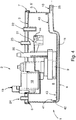
- An inventive pump arrangement comprises, as essential components, a liquid container 1, an electric motor-driven pump 2 provided in sections in the liquid container 1, as well as a closure cover 3 for the liquid container 1.
- the liquid container 1 provides a container base 4 and a circumferential side wall 5 which is formed on the container base 4 and is made in one piece with this.
- the closure cover 3 is provided for closing an opening of the liquid container 1.
- a circumferential seal 6 is provided to seal the closure cover 3 against the side wall 5 of the liquid container 1 .
- the closure cover 3 and the liquid container 1 are positively fixed to one another via a latching connection 7.
- a sump 8 is formed at the lowest point of the liquid container 1 in the area of the container bottom 4 in the orientation (installation position) of the pump arrangement shown, in which liquid optionally mixed with solids collects.
- the sump 8 is assigned a pump housing 9 and an impeller of the pump 2 (not shown) provided in the pump housing 9. Furthermore, a connection section 10 is provided on the liquid container 1, to which an external feed line (not shown) for the liquid can be connected. The connection section 10 is provided above the sump 8.
- the line section 11 has three annular walls 12, 13, 14 arranged concentrically to one another.
- An outer wall 12 is formed in one piece with the container base 4 of the liquid container 1 and protrudes from the container base 4 as a first rising wall 12 in the direction of the closure cover 3.
- a free end face 15 of the first rising wall 12 faces the closure cover 3.
- the case wall 13 is made in one piece with the closure cover 3. It protrudes from the closure cover 3 in the direction of the container bottom 4.
- a free end face 16 of the case wall 13 faces the container bottom 4. With a free end having the free end face 16, the drop wall 13 protrudes into the first rising wall 12 of the siphon-like line section 11.
- the drop wall 13 includes a second rising wall 14 in the area of a free end having the free end face 16, which, like the first rising wall 12, protrudes from the container bottom 4 in the direction of the closure lid 3 and is provided concentrically to the first rising wall 12.
- a free end face 17 of the second rising wall 14 faces the closure cover 3.
- the free end face 17 of the second rising wall 14 is - based on the installation position - arranged at the same level as the free end face 15 of the first rising wall 12.
- the second rising wall 14 directly adjoins the connection section 10 of the liquid container 1. Like the first rising wall 12, the second rising wall 14 is also made in one piece with the container bottom 4 of the liquid container 1.
- the pump 2 has an electric motor (not shown) and a motor housing 18 that accommodates the electric motor.
- the electric motor As part of the electric motor, one is in particular in the Motor housing 18 arranged control is provided, as well as a connection contact 19 leading out of the motor housing.
- the electric motor provides a stator and a rotor which is rotatably held in relation to the stator on a shaft carrying the pump wheel.
- An inlet opening and an outlet connection 20 are provided on the pump housing 9 adjacent to the container bottom 4.
- a floating body 21 is implemented as part of the pump arrangement, which is arranged in the liquid container 1 in a height-adjustable or pivotable manner.
- a magnet 44 is embedded in the floating body 21.
- the magnet 44 interacts with an active body (not shown), for example a Hall sensor or reed switch, which is provided in an active body recess 22 that is implemented as part of the closure cover 3.
- an active body for example a Hall sensor or reed switch
- two connection pieces 23, 24 are formed on the closure cover 3, which are used to connect the pump arrangement to additional lines, for example condensate lines.
- the liquid optionally mixed with solids is fed to the liquid container 1 via the feed line (not shown) and the connection section 10.
- the liquid flows in a flow direction 25 and, after passing through the connection section 10, reaches the effective area of the siphon-like line section 11, which is arranged in front of the feed line and the connection section 10 and is designed as an odor trap, relative to the flow direction 25, and optionally flows through it
- Liquid mixed with solids thus first enters the feed line (not shown) and then reaches the connection section 10, which is arranged upstream of the feed line in relation to the flow direction 25 of the connection section 10 arrives.
- the walls 12, 13, 14 of the siphon-like line section 11 interact here like a labyrinth.
- the liquid flows through an annular opening 29 defined by the free end face 15 and the jacket of the drop wall 13 into the Storage area 28 of the liquid container 1.
- the liquid initially collects at the lowest point, i.e. in the area of the sump 8 of the liquid container 1.
- the position of the float 21 is defined depending on the fill level of the liquid container 1. As soon as the float 21 has a defined position relative to the in The active body provided for the active body recess 22 assumes a control signal for the pump 2 is generated.
- the pump 2 starts up and the liquid, which enters the same via the inlet opening of the pump housing 9, is pumped out via the drain connection 20 and a drain line (not shown).
- a pump arrangement according to the invention for cooking appliances is shown as an example.
- the liquid mixed with solids for example roasting residues
- a pump arrangement according to the invention can alternatively be provided in domestic appliances which carry water, for example in dishwashers or washing machines, in commercial appliances which carry water or in sanitary facilities.
- FIG. 1 and 2 While according to the first embodiment of the invention according to the Fig. 1 and 2 the siphon-like line section 11 of the pump arrangement is formed by the three concentrically associated, labyrinthine cooperating walls 12, 13, 14, provides a second embodiment of a pump arrangement according to the invention according to FIG Fig. 3 two disk-like walls 32, 33 in front.
- a first wall 32 is implemented as a drop wall 32 which is formed in one piece with the closure cover 3 and extends parallel to a side wall section 5 ′ having the connection section 10 of the pump arrangement.
- a free edge 34 of the case wall 32 is provided facing the container bottom 4.
- a second wall 33 is implemented as a rising wall 33. The rising wall 33 protrudes from the container bottom 4 in the direction of the closure cover 3 of the pump arrangement.
- a free edge 36 of the rising wall 33 is provided above the free edge 34 of the drop wall 32 in relation to the installation position of the pump arrangement shown.
- the rising wall 33 is oriented parallel to the falling wall 32. While the rising wall 33 is preferably connected in one piece to the side wall 5, seals (not shown) are provided between the drop wall 32 and the side wall 5 to realize a gas-tight connection of the drop wall 32 with the side wall 5 of the liquid container 1.
- the horizontal level of the free edge 36 of the rising wall 33 relative to the sump 8 of the liquid container 1 ensures that the liquid reservoir 35 is also filled with the liquid optionally mixed with solids when the liquid is completely or almost completely conveyed away from the storage area 28 is.
- the siphon-like line section 11 designed as an odor stop, is formed in the region of the container bottom 4.
- an intermediate base 40 extending essentially parallel to the container base 4 is provided.
- a circumferential web 41 is formed on the edge of the intermediate floor 40.
- the web 41 serves to accommodate a circumferential seal 42, which is provided between the side wall 5 and the web 41 of the intermediate floor 40 in the assembly position shown.
- the siphon-like, angled line section 11 is consequently formed gas-tight between the container bottom 4, the side wall 5 and the intermediate bottom 40.
- a passage opening 43 for the liquid optionally mixed with solids is provided in the intermediate base 40.
- the liquid reaches the sump 8 of the liquid container 1 formed above the intermediate floor 40. If the pump 2 of the pump arrangement is operated and the liquid optionally mixed with solids is conveyed away from the storage area 28 of the liquid container 1, residual liquid always remains in the deep lying part of the siphon-like line section 11, which serves as a liquid reservoir.
Landscapes
- Engineering & Computer Science (AREA)
- Mechanical Engineering (AREA)
- General Engineering & Computer Science (AREA)
- Structures Of Non-Positive Displacement Pumps (AREA)
Claims (13)
- Système de pompe comprenant- une pompe (2) à entraînement électrique servant à transporter un liquide, comportant une roue de pompe fixée à un arbre rotatif et un carter de pompe (9) entourant la roue de pompe du moins sur certaines sections, un orifice d'entrée destiné au liquide et une tubulure de sortie (20) destinée au liquide étant prévus sur le carter de pompe.- un récipient de liquide (1) conçu pour recevoir le liquide, comportant un fond de récipient (4), une paroi latérale (5) et un orifice opposé au fond de récipient (4), une section de raccordement (10) destinée à une conduite d'alimentation extérieure et un collecteur (8) conçu pour recevoir la roue de pompe et le carter de pompe (9) étant prévus sur le récipient de liquide (1), et- une section de conduite en forme de siphon (11) destinée au liquide, laquelle sert à lutter contre les odeurs,
la section de conduite en forme de siphon (11) étant prévue en amont de la section de raccordement (10) du récipient de liquide (1) vue dans une direction d'écoulement (25) du liquide, de sorte que, lors du fonctionnement, le liquide s'écoule d'abord à travers la section de raccordement (10) puis à travers la section de conduite en forme de siphon (11),
la section de conduite en forme de siphon (11) conçue pour lutter contre les odeurs étant intégrée spatialement dans le récipient de liquide (1),
caractérisé
en ce qu'un corps flottant (21) est réalisé, lequel est disposé dans le récipient de liquide (1) de façon à pouvoir être réglé en hauteur ou à pouvoir pivoter, un aimant (44) étant inséré dans le corps flottant (21), lequel aimant interagit avec un corps actif prévu dans un évidement de corps actif (22), l'évidement de corps actif (22) étant réalisé de façon à faire partie d'un couvercle de fermeture (3),
la position du corps flottant (21) étant définie en fonction du niveau de remplissage du récipient de liquide (1), un signal de commande destiné à la pompe (2) étant généré dès que le corps flottant (21) adopte une position relative définie par rapport au corps actif. - Système de pompe selon la revendication 1, dans lequel le liquide présente des solides et/ou est mélangé avec des solides.
- Système de pompe selon la revendication 1 ou 2, caractérisé en ce que le couvercle de fermeture (3) est prévu comme un couvercle de fermeture (3) pouvant être placé sur la paroi latérale (5) du récipient de liquide (1) pour fermer l'orifice, un joint circonférentiel (6) étant prévu de préférence entre le couvercle de fermeture (3) et la paroi latérale (5).
- Système de pompe selon l'une des revendications 1 à 3, caractérisé en ce que la section de conduite en forme de siphon (11) prévoit une pluralité de parois (12, 13, 14, 32, 33) associées les unes aux autres à la manière d'un labyrinthe, lesquelles parois s'étendent de façon à être entourées par la paroi latérale (5) du récipient de liquide (1).
- Système de pompe selon l'une des revendications 1 à 4, caractérisé en ce qu'une première paroi ascendante (12, 33) s'étendant depuis le fond de récipient (4) en direction de l'orifice est prévue comme faisant partie de la section de conduite en forme de siphon (11) et/ou qu'une paroi descendante (13, 32) s'étendant depuis le couvercle de fermeture (3) en direction du fond de récipient (4) est prévue comme faisant partie de la section de conduite en forme de siphon (11).
- Système de pompe selon la revendication 5, caractérisé en ce que la paroi ascendante (12, 14, 33) fait saillie à partir du fond de récipient (4) et/ou est réalisée d'une seule pièce avec le fond de récipient (4) et/ou la paroi latérale (5) du récipient de liquide (1), et/ou que la paroi descendante (13, 32) fait saillie à partir du couvercle de fermeture (3) et/ou est réalisée d'une seule pièce avec le couvercle de fermeture (3).
- Système de pompe selon l'une des revendications 5 ou 6, caractérisé en ce que la première paroi ascendante (12) et/ou la paroi descendante (13) de la section de conduite en forme de siphon (11) sont annulaires et/ou sont disposées l'une autour de l'autre de préférence de façon concentrique.
- Système de pompe selon la revendication 7, caractérisé en ce que la première paroi ascendante (12) entoure du côté externe (13) une extrémité libre de la paroi descendante faisant face au fond de récipient (4) avec une extrémité libre faisant face au couvercle de fermeture (3).
- Système de pompe selon l'une des revendications 5 à 8, caractérisé en ce que, dans une position d'assemblage, une face frontale libre (15) de la première paroi ascendante (12) faisant face au couvercle de fermeture (3) est prévue de façon à être espacée du couvercle de fermeture (3) et/ou qu'une seconde face frontale libre (16) de la paroi descendante (13) faisant face au fond de récipient (4) est prévue de façon à être espacée du fond de récipient (4).
- Système de pompe selon l'une des revendications 5 à 9, caractérisé en ce qu'une seconde paroi ascendante (14) de la section de conduite en forme de siphon (11) faisant saillie à partir du fond de récipient (4) en direction de l'orifice est prévue, laquelle paroi ascendante est disposée de préférence de façon concentrique par rapport à la première paroi ascendante (12) et/ou à la paroi descendante (13) et/ou fait saillie dans l'extrémité libre de la paroi descendante (13) de la section de conduite en forme de siphon (11) avec une extrémité libre faisant face au couvercle de fermeture (3), et/ou que l'extrémité libre de la première paroi ascendante (12) et l'extrémité libre de la seconde paroi ascendante (14) sont prévues à un même niveau de hauteur horizontal.
- Système de pompe selon la revendication 10, caractérisé en ce que les parois (12, 13, 14) sont placées en cascade les unes dans les autres et/ou présentent un diamètre différent ou une section transversale différente les unes des autres.
- Système de pompe selon l'une des revendications 1 à 11, caractérisé en ce que la section de conduite en forme de siphon (11) est formée entre le fond de récipient (4) et un fond intermédiaire (40) espacé du fond de récipient (4), le fond intermédiaire (40) prévoyant une entretoise circonférentielle (41), et un joint circonférentiel (42) étant prévu entre l'entretoise (41) du fond intermédiaire (40) et la paroi latérale (5).
- Système de pompe selon l'une des revendications 1 à 12, caractérisé en ce que la section de conduite en forme de siphon (11) est intégrée dans le récipient de liquide (1) de telle sorte que le liquide mélangé avec des solides et amené par l'intermédiaire de la section de raccordement (10) s'écoule initialement à travers la section de conduite en forme de siphon (11) avec un réservoir de liquide (27, 35) faisant partie de la section de conduite en forme de siphon (11) et de telle sorte qu'après avoir quitté la section de conduite en forme de siphon (11), il peut être évacué du récipient de liquide (1) au moyen de la pompe à entraînement électrique (2).
Applications Claiming Priority (1)
| Application Number | Priority Date | Filing Date | Title |
|---|---|---|---|
| DE102015108977.7A DE102015108977B4 (de) | 2015-06-08 | 2015-06-08 | Pumpenanordnung |
Publications (2)
| Publication Number | Publication Date |
|---|---|
| EP3104016A1 EP3104016A1 (fr) | 2016-12-14 |
| EP3104016B1 true EP3104016B1 (fr) | 2020-09-09 |
Family
ID=56112804
Family Applications (1)
| Application Number | Title | Priority Date | Filing Date |
|---|---|---|---|
| EP16020220.6A Active EP3104016B1 (fr) | 2015-06-08 | 2016-06-07 | Système de pompe |
Country Status (2)
| Country | Link |
|---|---|
| EP (1) | EP3104016B1 (fr) |
| DE (1) | DE102015108977B4 (fr) |
Citations (1)
| Publication number | Priority date | Publication date | Assignee | Title |
|---|---|---|---|---|
| US5868011A (en) * | 1997-04-04 | 1999-02-09 | General Electric Company | Water traps for washing machines |
Family Cites Families (4)
| Publication number | Priority date | Publication date | Assignee | Title |
|---|---|---|---|---|
| JP2000051134A (ja) * | 1998-08-17 | 2000-02-22 | Mitsubishi Electric Corp | 組込み形食器洗浄機 |
| KR101270538B1 (ko) * | 2006-07-12 | 2013-06-03 | 삼성전자주식회사 | 식기세척기 |
| EP1930493A1 (fr) * | 2006-12-04 | 2008-06-11 | Bonferraro S.p.A. | Machine à laver avec un évier integré |
| ATE430226T1 (de) * | 2007-01-15 | 2009-05-15 | Kessel Gmbh | Hebeanlage |
-
2015
- 2015-06-08 DE DE102015108977.7A patent/DE102015108977B4/de active Active
-
2016
- 2016-06-07 EP EP16020220.6A patent/EP3104016B1/fr active Active
Patent Citations (1)
| Publication number | Priority date | Publication date | Assignee | Title |
|---|---|---|---|---|
| US5868011A (en) * | 1997-04-04 | 1999-02-09 | General Electric Company | Water traps for washing machines |
Also Published As
| Publication number | Publication date |
|---|---|
| DE102015108977A1 (de) | 2016-12-08 |
| DE102015108977B4 (de) | 2021-10-21 |
| EP3104016A1 (fr) | 2016-12-14 |
Similar Documents
| Publication | Publication Date | Title |
|---|---|---|
| EP1209275B1 (fr) | Dispositif pour l' évacuation de l'eau de lavage dans une machine à laver | |
| DE102011005138A1 (de) | Pumpe | |
| DE2114688A1 (de) | Abortanlage | |
| EP2794978A2 (fr) | Dispositif d'introduction de lessive pour un appareil ménager destiné à l'entretien du linge et appareil ménager destiné à l'entretien du linge | |
| DE8218877U1 (de) | Einrichtung insbesondere an gechirrspuelmaschinen zurniveauregelung | |
| CH707892B1 (de) | Wäschetrockner mit Abwasserpumpe. | |
| EP3104016B1 (fr) | Système de pompe | |
| EP1775395B1 (fr) | Dispositif d'écoulement pour installations sanitaires | |
| EP2573288B1 (fr) | Installation de relèvement d'eaux usées | |
| DE202004017607U1 (de) | Einsatzteil und Ablaufsystem | |
| DE4033957C2 (fr) | ||
| DE19921441B4 (de) | Haushaltgerät, insbesondere Waschmaschine, Waschtrockner oder Geschirrspülmaschine | |
| DE4432224A1 (de) | Vorrichtung zum Verbessern des Ansaugverhaltens von Strömungsförderpumpen | |
| EP1127988B1 (fr) | Regard d'évacuation muni d'une fermeture à flotteur | |
| DE102010044940B4 (de) | Abwasserablauf mit Geruchsverschluss | |
| EP3890861A1 (fr) | Boîtier de palier et procédé d'élimination d'impuretés d'un boîtier de palier | |
| DE102004061306A1 (de) | Waschmittel-Einspüleinrichtung | |
| DE102015220125B4 (de) | Tankeinfüllstutzen | |
| DE8130642U1 (de) | Dosierventil, insbesondere zur abgabe viskoser fluessigkeiten | |
| DE3002450A1 (de) | Entwicklungsvorrichtung fuer fotopapiere | |
| EP3405677A1 (fr) | Dispositif de purge pour une pompe dans un réservoir | |
| DE102018210207B4 (de) | Wasserführendes Haushaltsgerät mit einer Impellerpumpe | |
| EP2024549B1 (fr) | Lave-linge muni d'un flexible de vidange de secours | |
| EP2898812B1 (fr) | Automate de nettoyage transportant de l'eau, en particulier lave-vaisselle automatique commandé par programme | |
| WO2018114511A1 (fr) | Installation de relevage d'eaux usées comprenant un mécanisme de coupe |
Legal Events
| Date | Code | Title | Description |
|---|---|---|---|
| PUAI | Public reference made under article 153(3) epc to a published international application that has entered the european phase |
Free format text: ORIGINAL CODE: 0009012 |
|
| STAA | Information on the status of an ep patent application or granted ep patent |
Free format text: STATUS: THE APPLICATION HAS BEEN PUBLISHED |
|
| AK | Designated contracting states |
Kind code of ref document: A1 Designated state(s): AL AT BE BG CH CY CZ DE DK EE ES FI FR GB GR HR HU IE IS IT LI LT LU LV MC MK MT NL NO PL PT RO RS SE SI SK SM TR |
|
| AX | Request for extension of the european patent |
Extension state: BA ME |
|
| STAA | Information on the status of an ep patent application or granted ep patent |
Free format text: STATUS: REQUEST FOR EXAMINATION WAS MADE |
|
| 17P | Request for examination filed |
Effective date: 20170614 |
|
| RBV | Designated contracting states (corrected) |
Designated state(s): AL AT BE BG CH CY CZ DE DK EE ES FI FR GB GR HR HU IE IS IT LI LT LU LV MC MK MT NL NO PL PT RO RS SE SI SK SM TR |
|
| STAA | Information on the status of an ep patent application or granted ep patent |
Free format text: STATUS: EXAMINATION IS IN PROGRESS |
|
| 17Q | First examination report despatched |
Effective date: 20190527 |
|
| REG | Reference to a national code |
Ref country code: DE Ref legal event code: R079 Ref document number: 502016011070 Country of ref document: DE Free format text: PREVIOUS MAIN CLASS: F04D0029420000 Ipc: F04D0015020000 |
|
| GRAP | Despatch of communication of intention to grant a patent |
Free format text: ORIGINAL CODE: EPIDOSNIGR1 |
|
| STAA | Information on the status of an ep patent application or granted ep patent |
Free format text: STATUS: GRANT OF PATENT IS INTENDED |
|
| RIC1 | Information provided on ipc code assigned before grant |
Ipc: F04D 15/02 20060101AFI20200423BHEP Ipc: F04D 13/08 20060101ALI20200423BHEP Ipc: F04D 29/42 20060101ALI20200423BHEP |
|
| INTG | Intention to grant announced |
Effective date: 20200511 |
|
| GRAS | Grant fee paid |
Free format text: ORIGINAL CODE: EPIDOSNIGR3 |
|
| GRAA | (expected) grant |
Free format text: ORIGINAL CODE: 0009210 |
|
| STAA | Information on the status of an ep patent application or granted ep patent |
Free format text: STATUS: THE PATENT HAS BEEN GRANTED |
|
| AK | Designated contracting states |
Kind code of ref document: B1 Designated state(s): AL AT BE BG CH CY CZ DE DK EE ES FI FR GB GR HR HU IE IS IT LI LT LU LV MC MK MT NL NO PL PT RO RS SE SI SK SM TR |
|
| REG | Reference to a national code |
Ref country code: GB Ref legal event code: FG4D Free format text: NOT ENGLISH |
|
| REG | Reference to a national code |
Ref country code: AT Ref legal event code: REF Ref document number: 1311914 Country of ref document: AT Kind code of ref document: T Effective date: 20200915 Ref country code: CH Ref legal event code: EP Ref country code: CH Ref legal event code: NV Representative=s name: COSMOVICI INTELLECTUAL PROPERTY SARL, CH |
|
| REG | Reference to a national code |
Ref country code: IE Ref legal event code: FG4D Free format text: LANGUAGE OF EP DOCUMENT: GERMAN |
|
| REG | Reference to a national code |
Ref country code: DE Ref legal event code: R096 Ref document number: 502016011070 Country of ref document: DE |
|
| REG | Reference to a national code |
Ref country code: LT Ref legal event code: MG4D |
|
| PG25 | Lapsed in a contracting state [announced via postgrant information from national office to epo] |
Ref country code: SE Free format text: LAPSE BECAUSE OF FAILURE TO SUBMIT A TRANSLATION OF THE DESCRIPTION OR TO PAY THE FEE WITHIN THE PRESCRIBED TIME-LIMIT Effective date: 20200909 Ref country code: BG Free format text: LAPSE BECAUSE OF FAILURE TO SUBMIT A TRANSLATION OF THE DESCRIPTION OR TO PAY THE FEE WITHIN THE PRESCRIBED TIME-LIMIT Effective date: 20201209 Ref country code: NO Free format text: LAPSE BECAUSE OF FAILURE TO SUBMIT A TRANSLATION OF THE DESCRIPTION OR TO PAY THE FEE WITHIN THE PRESCRIBED TIME-LIMIT Effective date: 20201209 Ref country code: FI Free format text: LAPSE BECAUSE OF FAILURE TO SUBMIT A TRANSLATION OF THE DESCRIPTION OR TO PAY THE FEE WITHIN THE PRESCRIBED TIME-LIMIT Effective date: 20200909 Ref country code: GR Free format text: LAPSE BECAUSE OF FAILURE TO SUBMIT A TRANSLATION OF THE DESCRIPTION OR TO PAY THE FEE WITHIN THE PRESCRIBED TIME-LIMIT Effective date: 20201210 Ref country code: LT Free format text: LAPSE BECAUSE OF FAILURE TO SUBMIT A TRANSLATION OF THE DESCRIPTION OR TO PAY THE FEE WITHIN THE PRESCRIBED TIME-LIMIT Effective date: 20200909 Ref country code: HR Free format text: LAPSE BECAUSE OF FAILURE TO SUBMIT A TRANSLATION OF THE DESCRIPTION OR TO PAY THE FEE WITHIN THE PRESCRIBED TIME-LIMIT Effective date: 20200909 |
|
| REG | Reference to a national code |
Ref country code: NL Ref legal event code: MP Effective date: 20200909 |
|
| PG25 | Lapsed in a contracting state [announced via postgrant information from national office to epo] |
Ref country code: LV Free format text: LAPSE BECAUSE OF FAILURE TO SUBMIT A TRANSLATION OF THE DESCRIPTION OR TO PAY THE FEE WITHIN THE PRESCRIBED TIME-LIMIT Effective date: 20200909 Ref country code: PL Free format text: LAPSE BECAUSE OF FAILURE TO SUBMIT A TRANSLATION OF THE DESCRIPTION OR TO PAY THE FEE WITHIN THE PRESCRIBED TIME-LIMIT Effective date: 20200909 Ref country code: RS Free format text: LAPSE BECAUSE OF FAILURE TO SUBMIT A TRANSLATION OF THE DESCRIPTION OR TO PAY THE FEE WITHIN THE PRESCRIBED TIME-LIMIT Effective date: 20200909 |
|
| PG25 | Lapsed in a contracting state [announced via postgrant information from national office to epo] |
Ref country code: SM Free format text: LAPSE BECAUSE OF FAILURE TO SUBMIT A TRANSLATION OF THE DESCRIPTION OR TO PAY THE FEE WITHIN THE PRESCRIBED TIME-LIMIT Effective date: 20200909 Ref country code: RO Free format text: LAPSE BECAUSE OF FAILURE TO SUBMIT A TRANSLATION OF THE DESCRIPTION OR TO PAY THE FEE WITHIN THE PRESCRIBED TIME-LIMIT Effective date: 20200909 Ref country code: PT Free format text: LAPSE BECAUSE OF FAILURE TO SUBMIT A TRANSLATION OF THE DESCRIPTION OR TO PAY THE FEE WITHIN THE PRESCRIBED TIME-LIMIT Effective date: 20210111 Ref country code: EE Free format text: LAPSE BECAUSE OF FAILURE TO SUBMIT A TRANSLATION OF THE DESCRIPTION OR TO PAY THE FEE WITHIN THE PRESCRIBED TIME-LIMIT Effective date: 20200909 Ref country code: NL Free format text: LAPSE BECAUSE OF FAILURE TO SUBMIT A TRANSLATION OF THE DESCRIPTION OR TO PAY THE FEE WITHIN THE PRESCRIBED TIME-LIMIT Effective date: 20200909 Ref country code: CZ Free format text: LAPSE BECAUSE OF FAILURE TO SUBMIT A TRANSLATION OF THE DESCRIPTION OR TO PAY THE FEE WITHIN THE PRESCRIBED TIME-LIMIT Effective date: 20200909 |
|
| PG25 | Lapsed in a contracting state [announced via postgrant information from national office to epo] |
Ref country code: ES Free format text: LAPSE BECAUSE OF FAILURE TO SUBMIT A TRANSLATION OF THE DESCRIPTION OR TO PAY THE FEE WITHIN THE PRESCRIBED TIME-LIMIT Effective date: 20200909 Ref country code: AL Free format text: LAPSE BECAUSE OF FAILURE TO SUBMIT A TRANSLATION OF THE DESCRIPTION OR TO PAY THE FEE WITHIN THE PRESCRIBED TIME-LIMIT Effective date: 20200909 Ref country code: IS Free format text: LAPSE BECAUSE OF FAILURE TO SUBMIT A TRANSLATION OF THE DESCRIPTION OR TO PAY THE FEE WITHIN THE PRESCRIBED TIME-LIMIT Effective date: 20210109 |
|
| REG | Reference to a national code |
Ref country code: DE Ref legal event code: R097 Ref document number: 502016011070 Country of ref document: DE |
|
| PG25 | Lapsed in a contracting state [announced via postgrant information from national office to epo] |
Ref country code: SK Free format text: LAPSE BECAUSE OF FAILURE TO SUBMIT A TRANSLATION OF THE DESCRIPTION OR TO PAY THE FEE WITHIN THE PRESCRIBED TIME-LIMIT Effective date: 20200909 |
|
| PLBE | No opposition filed within time limit |
Free format text: ORIGINAL CODE: 0009261 |
|
| STAA | Information on the status of an ep patent application or granted ep patent |
Free format text: STATUS: NO OPPOSITION FILED WITHIN TIME LIMIT |
|
| 26N | No opposition filed |
Effective date: 20210610 |
|
| PG25 | Lapsed in a contracting state [announced via postgrant information from national office to epo] |
Ref country code: SI Free format text: LAPSE BECAUSE OF FAILURE TO SUBMIT A TRANSLATION OF THE DESCRIPTION OR TO PAY THE FEE WITHIN THE PRESCRIBED TIME-LIMIT Effective date: 20200909 Ref country code: DK Free format text: LAPSE BECAUSE OF FAILURE TO SUBMIT A TRANSLATION OF THE DESCRIPTION OR TO PAY THE FEE WITHIN THE PRESCRIBED TIME-LIMIT Effective date: 20200909 |
|
| PG25 | Lapsed in a contracting state [announced via postgrant information from national office to epo] |
Ref country code: IT Free format text: LAPSE BECAUSE OF FAILURE TO SUBMIT A TRANSLATION OF THE DESCRIPTION OR TO PAY THE FEE WITHIN THE PRESCRIBED TIME-LIMIT Effective date: 20200909 |
|
| PG25 | Lapsed in a contracting state [announced via postgrant information from national office to epo] |
Ref country code: MC Free format text: LAPSE BECAUSE OF FAILURE TO SUBMIT A TRANSLATION OF THE DESCRIPTION OR TO PAY THE FEE WITHIN THE PRESCRIBED TIME-LIMIT Effective date: 20200909 |
|
| GBPC | Gb: european patent ceased through non-payment of renewal fee |
Effective date: 20210607 |
|
| PG25 | Lapsed in a contracting state [announced via postgrant information from national office to epo] |
Ref country code: LU Free format text: LAPSE BECAUSE OF NON-PAYMENT OF DUE FEES Effective date: 20210607 |
|
| PG25 | Lapsed in a contracting state [announced via postgrant information from national office to epo] |
Ref country code: IE Free format text: LAPSE BECAUSE OF NON-PAYMENT OF DUE FEES Effective date: 20210607 Ref country code: GB Free format text: LAPSE BECAUSE OF NON-PAYMENT OF DUE FEES Effective date: 20210607 |
|
| PG25 | Lapsed in a contracting state [announced via postgrant information from national office to epo] |
Ref country code: FR Free format text: LAPSE BECAUSE OF NON-PAYMENT OF DUE FEES Effective date: 20210630 |
|
| PG25 | Lapsed in a contracting state [announced via postgrant information from national office to epo] |
Ref country code: HU Free format text: LAPSE BECAUSE OF FAILURE TO SUBMIT A TRANSLATION OF THE DESCRIPTION OR TO PAY THE FEE WITHIN THE PRESCRIBED TIME-LIMIT; INVALID AB INITIO Effective date: 20160607 |
|
| PG25 | Lapsed in a contracting state [announced via postgrant information from national office to epo] |
Ref country code: CY Free format text: LAPSE BECAUSE OF FAILURE TO SUBMIT A TRANSLATION OF THE DESCRIPTION OR TO PAY THE FEE WITHIN THE PRESCRIBED TIME-LIMIT Effective date: 20200909 |
|
| P01 | Opt-out of the competence of the unified patent court (upc) registered |
Effective date: 20230607 |
|
| PG25 | Lapsed in a contracting state [announced via postgrant information from national office to epo] |
Ref country code: MK Free format text: LAPSE BECAUSE OF FAILURE TO SUBMIT A TRANSLATION OF THE DESCRIPTION OR TO PAY THE FEE WITHIN THE PRESCRIBED TIME-LIMIT Effective date: 20200909 |
|
| PG25 | Lapsed in a contracting state [announced via postgrant information from national office to epo] |
Ref country code: MT Free format text: LAPSE BECAUSE OF FAILURE TO SUBMIT A TRANSLATION OF THE DESCRIPTION OR TO PAY THE FEE WITHIN THE PRESCRIBED TIME-LIMIT Effective date: 20200909 |
|
| PGFP | Annual fee paid to national office [announced via postgrant information from national office to epo] |
Ref country code: DE Payment date: 20250630 Year of fee payment: 10 |
|
| PGFP | Annual fee paid to national office [announced via postgrant information from national office to epo] |
Ref country code: BE Payment date: 20250624 Year of fee payment: 10 |
|
| PGFP | Annual fee paid to national office [announced via postgrant information from national office to epo] |
Ref country code: AT Payment date: 20250617 Year of fee payment: 10 |
|
| PGFP | Annual fee paid to national office [announced via postgrant information from national office to epo] |
Ref country code: CH Payment date: 20250701 Year of fee payment: 10 |
|
| PG25 | Lapsed in a contracting state [announced via postgrant information from national office to epo] |
Ref country code: TR Free format text: LAPSE BECAUSE OF FAILURE TO SUBMIT A TRANSLATION OF THE DESCRIPTION OR TO PAY THE FEE WITHIN THE PRESCRIBED TIME-LIMIT Effective date: 20200909 |