EP3103587B1 - Deburring machine for deburring metallic workpieces - Google Patents
Deburring machine for deburring metallic workpieces Download PDFInfo
- Publication number
- EP3103587B1 EP3103587B1 EP16000170.7A EP16000170A EP3103587B1 EP 3103587 B1 EP3103587 B1 EP 3103587B1 EP 16000170 A EP16000170 A EP 16000170A EP 3103587 B1 EP3103587 B1 EP 3103587B1
- Authority
- EP
- European Patent Office
- Prior art keywords
- shore
- belt
- deburring machine
- machine according
- contact roller
- Prior art date
- Legal status (The legal status is an assumption and is not a legal conclusion. Google has not performed a legal analysis and makes no representation as to the accuracy of the status listed.)
- Active
Links
- 239000011248 coating agent Substances 0.000 claims description 31
- 238000000576 coating method Methods 0.000 claims description 31
- 229920002943 EPDM rubber Polymers 0.000 claims description 7
- 239000002184 metal Substances 0.000 claims description 7
- 238000000034 method Methods 0.000 claims description 7
- 229920001971 elastomer Polymers 0.000 claims description 6
- 244000043261 Hevea brasiliensis Species 0.000 claims description 2
- 229920003052 natural elastomer Polymers 0.000 claims description 2
- 229920001194 natural rubber Polymers 0.000 claims description 2
- 239000006261 foam material Substances 0.000 claims 2
- 230000001413 cellular effect Effects 0.000 claims 1
- 235000019589 hardness Nutrition 0.000 description 34
- 238000007639 printing Methods 0.000 description 26
- 239000004744 fabric Substances 0.000 description 6
- 238000010586 diagram Methods 0.000 description 4
- 230000005540 biological transmission Effects 0.000 description 2
- 238000010073 coating (rubber) Methods 0.000 description 2
- 238000011161 development Methods 0.000 description 2
- 230000018109 developmental process Effects 0.000 description 2
- 239000006260 foam Substances 0.000 description 2
- 239000000446 fuel Substances 0.000 description 2
- 238000003754 machining Methods 0.000 description 2
- 241000196324 Embryophyta Species 0.000 description 1
- 239000004952 Polyamide Substances 0.000 description 1
- 229910000831 Steel Inorganic materials 0.000 description 1
- 238000005299 abrasion Methods 0.000 description 1
- 239000007799 cork Substances 0.000 description 1
- 230000007423 decrease Effects 0.000 description 1
- 230000001419 dependent effect Effects 0.000 description 1
- 229910003460 diamond Inorganic materials 0.000 description 1
- 239000010432 diamond Substances 0.000 description 1
- 230000000694 effects Effects 0.000 description 1
- 238000005516 engineering process Methods 0.000 description 1
- 239000000835 fiber Substances 0.000 description 1
- 238000009434 installation Methods 0.000 description 1
- 239000000463 material Substances 0.000 description 1
- 230000007246 mechanism Effects 0.000 description 1
- 230000002093 peripheral effect Effects 0.000 description 1
- 229920002647 polyamide Polymers 0.000 description 1
- 239000010959 steel Substances 0.000 description 1
- 230000008646 thermal stress Effects 0.000 description 1
- 238000004073 vulcanization Methods 0.000 description 1
- XLYOFNOQVPJJNP-UHFFFAOYSA-N water Substances O XLYOFNOQVPJJNP-UHFFFAOYSA-N 0.000 description 1
Images


Classifications
-
- B—PERFORMING OPERATIONS; TRANSPORTING
- B24—GRINDING; POLISHING
- B24B—MACHINES, DEVICES, OR PROCESSES FOR GRINDING OR POLISHING; DRESSING OR CONDITIONING OF ABRADING SURFACES; FEEDING OF GRINDING, POLISHING, OR LAPPING AGENTS
- B24B21/00—Machines or devices using grinding or polishing belts; Accessories therefor
- B24B21/04—Machines or devices using grinding or polishing belts; Accessories therefor for grinding plane surfaces
- B24B21/06—Machines or devices using grinding or polishing belts; Accessories therefor for grinding plane surfaces involving members with limited contact area pressing the belt against the work, e.g. shoes sweeping across the whole area to be ground
- B24B21/08—Pressure shoes; Pressure members, e.g. backing belts
-
- B—PERFORMING OPERATIONS; TRANSPORTING
- B24—GRINDING; POLISHING
- B24B—MACHINES, DEVICES, OR PROCESSES FOR GRINDING OR POLISHING; DRESSING OR CONDITIONING OF ABRADING SURFACES; FEEDING OF GRINDING, POLISHING, OR LAPPING AGENTS
- B24B21/00—Machines or devices using grinding or polishing belts; Accessories therefor
- B24B21/002—Machines or devices using grinding or polishing belts; Accessories therefor for grinding edges or bevels
-
- B—PERFORMING OPERATIONS; TRANSPORTING
- B24—GRINDING; POLISHING
- B24B—MACHINES, DEVICES, OR PROCESSES FOR GRINDING OR POLISHING; DRESSING OR CONDITIONING OF ABRADING SURFACES; FEEDING OF GRINDING, POLISHING, OR LAPPING AGENTS
- B24B21/00—Machines or devices using grinding or polishing belts; Accessories therefor
- B24B21/04—Machines or devices using grinding or polishing belts; Accessories therefor for grinding plane surfaces
- B24B21/12—Machines or devices using grinding or polishing belts; Accessories therefor for grinding plane surfaces involving a contact wheel or roller pressing the belt against the work
Definitions
- the present invention relates to deburring machines for deburring metal workpieces according to the preambles of claims 1 and 3.
- a deburring machine for deburring of metal workpieces known, with a rotating about its longitudinal axis contact roller made of steel.
- On the outside of the contact roller is a soft covering made from up to 30 mm thick rubber coating vulcanized.
- Around this contact roller around an endless revolving sanding belt is provided on the outside of the actual abrasive is attached.
- This abrasive belt is not attached to the contact roller, but is held circumferentially on the contact roller and a second roller and clamped so that the drive of the abrasive belt can be done for example via the contact roller.
- the endless rotating abrasive belt is stretched so tight that no slip, or at least no appreciable, arises between the contact roller and the abrasive belt.
- the contact pressure at other locations, in particular on surfaces of the workpiece is correspondingly lower and the removal on the surface correspondingly lower. That is also wanted, because the workpiece should be deburred.
- Such hard contact rollers are advantageously used for workpieces that were made by laser or water jet technology, because these workpieces are comparatively thick over the entire workpiece surface.
- the workpiece may be warped due to thermal influences.
- the abrasive belt must be made yielding during deburring, so that the grinding belt can follow the contour of the workpiece at least partially and the machining of the surface of the workpiece is reduced to a minimum, because an unnecessary processing of the workpiece, in particular its surface requires one high power requirement of the deburring machine, leading to high wear of the grinding belt and has a high thermal stress on the workpiece result, which in extreme cases can lead to further distortion of the workpiece.
- the film In order to achieve the hardness required for the respective workpiece, the film must be changed together with the grinding arc at a workpiece change, which is very expensive. In the event that another compliance with the new workpiece is required, even another contact roller with a different coating must be used, which is also very expensive. Likewise, the grinding arc change designed as very expensive.
- a contact disc for a belt grinding machine is known, on the contact roller a flexible work cushion is attached.
- This work cushion is surrounded by an abrasion-resistant, closed, flexible but non-stretchable material.
- This jacket formed of cork, polyamide fiber, metal fabric or the like may be in one piece or consist of several different layers.
- Such a contact disk is suitable for a particular application.
- a different hardness must be realized.
- the shell must be changed at a workpiece change, which is very expensive.
- another compliance with the new workpiece is required, even another contact roller with a different coating must be used, which is also very expensive.
- the present invention seeks to provide a deburring machine of the type mentioned above with a large compliance range at sufficient for deburring back pressure on the ridge, their handling is much easier.
- a deburring machine designed according to this technical teaching has the advantage that a comparatively high backpressure is built up on the ridge by the peripheral pressure band present in addition to the revolving grinding belt, in particular if this has a higher hardness than the resilient lining, in order to grind it off effectively. This allows the use of a softer coating, so that the compliance is increased, for example, better compensate for workpiece irregularities.
- Another advantage is that due to the comparatively hard pressure belt and the associated back pressure on the ridge a Damage to the sanding belt is avoided by sharp or protruding burrs.
- a very particular advantage is that for the exchange of the printing tape only the tension roller of the sanding belt, possibly even the tensioning device of the printing tape, need to be solved before the print tape can be removed and replaced by another. A removal of the heavy contact roller as in the DE 32 38 624 A1 not necessary. Thus, the printing tape can be replaced in a simple manner and replaced by a pressure belt of different hardness.
- the printing tape is stretched over its own tensioning device. This has the advantage that the printing tape can be stretched independently of the sanding belt, with the result that both the printing belt and the sanding belt are optimally tensioned in order to avoid slippage on the contact roller.
- the printing tape is tensioned so that the printing tape during the grinding process exerts a contact pressure on the pad roller located on the pad.
- the printing tape is at least as wide designed as the abrasive belt. This has the advantage that the desired back pressure over the entire width of the sanding belt is available.
- a pressure belt also means that a softer surface can be used, which has a high compliance, while the built-up by the pressure belt in conjunction with the sanding belt back pressure allows sufficient removal of the chip or burr without the sanding belt is damaged. Consequently, even a covering of a foam, in particular a technical cell foam, preferably of ethylene-propylene-diene rubber (EPDM), natural rubber, sponge rubber or sponge rubber with a hardness of 5 ° Shore to 25 ° Shore can be used without the abrasive belt Damage decreases, so that loops of up to 15 mm, in extreme cases even 20 mm, can be achieved during grinding.
- EPDM ethylene-propylene-diene rubber
- the contact roller has a diameter of 250 mm to 600 mm, preferably 400 mm. At present, contact rolls with a diameter of 180 mm are common. Such an enlarged contact roller has the advantage of enlarging the grinding surface on the burr, with the result that the burr is correspondingly longer machined and thus reliable removal of the burr and even a rounding of the edge is achieved.
- the pressure band has a structured surface on its side facing the lining of the contact roller.
- this structured surface has a structural depth of 0.1 mm to 2 mm, this has the advantage that protruding parts of the structured surface press into the comparatively soft coating and thus between the pressure band and the contact roller forms a positive fit, so that a good power transmission from the contact roller on the printing tape is carried out and thus the slip is minimized.
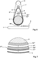
- a resilient covering with an average hardness of between 60 ° Shore and 70 ° Shore, preferably 65 ° Shore, is provided on the contact roller while the pressure band 5 "is constructed in three layers, with an inner layer (facing the contact roller) a fabric tape receiving the tensile forces, having a middle layer of a soft resilient covering with a hardness of 5 ° Shore to 25 ° Shore, preferably 25 ° Shore, and an outer layer (facing the abrasive tape) of a harder layer with 80 ° Shore until 100 ° Shore, preferably 90 ° Shore
- Another advantage is that after removal of the printing tape a contact roller with an average hardness of about 65 ° Shore is available, with which then a microsection can be created, which is not possible with a soft system. Thus, different operations can be completed on one and the same Entgratungsmaschine, which significantly increases the application of the Entratungsmaschine.
- FIG. 1 and 2 is a schematic representation of a first preferred embodiment of a deburring machine according to the invention shown.
- This deburring machine comprises a revolving conveyor belt 1 for transporting a workpiece 2, and a preferably electrically driven in a clockwise contact roller 3, on the surface of a soft EPDM formed soft and thus resilient coating 4 is applied, said resilient lining 4 is about 20 mm thick.
- Around the contact roller 3 around an endlessly circulating pressure belt 5 is provided, which is stretched over a tensioning device 6.
- To the contact roller 3 and the pressure belt 5 around an endless revolving belt 7 is provided, which is stretched over a tension roller 8.
- the tensioning device 6 comprises a roller 9 which is aligned coaxially with the contact roller 3 and which is tensioned by known spring mechanisms 10. Analogously, the tension roller 8 is constructed.
- the pressure belt 5 extends around the contact roller 3 on the one hand and on the other hand around the roller 9, the tensioning device 6 moving the roller 9 in order to tension the pressure belt 5.
- the covering 4 made of EPDM on the contact roller 3 has a thickness of approximately 20 mm and has a hardness of 15 ° Shore. It would also be conceivable to provide the coating with a hardness of only 5 ° Shore or up to 25 ° Shore.
- the thickness of the covering can vary between 5 mm and 50 mm.
- the printing tape 5 is constructed in two layers and has on its side facing the sanding belt 7, a comparatively hard layer 11 made of PVC, while the contact roller 3 facing inner side of the printing tape 5 is formed of a tensile fabric 12 having a textured surface.
- the hardness of the PVC layer 11 is approximately 5.33 times higher than the hardness of the lining 4 and is 80 ° Shore. In other embodiments, in particular with a hardness of the coating of 5 ° Shore, the PVC layer may also be 16 times harder.
- the structured surface of the fabric strip 12 of the printing tape 5 is at least partially pressed into the lining 4, so that a positive force transmission of the electrically driven contact roller 3 on the printing tape 5 takes place via this positive connection.
- the circulating around the pressure belt 5 sanding belt 7 is tensioned on the tension roller 8 so that the slip between the pressure belt 5 and the sanding belt 7 is reduced to a minimum, so that the electrically driven contact roller 3, the grinding belt 7 drives reliably and virtually without slippage.
- the contact roller 3 is adjusted so that the lowest point of the grinding belt 7 is below the upper edge of the workpiece 2. If the workpiece 2 now passes under the contact roller 3, the grinding belt 7, supported by the pressure belt 5 and the lining 4, exerts a force on the ridge projecting from the workpiece 2, not shown here, and wipes it off. Because the contact roller 3 has a diameter of 400 mm, a comparatively long processing time is available, so that the burr is reliably removed. In the event that the workpiece has unevenness or distortion, due to the soft and 20 mm thick coating 4, the grinding belt machine is capable of yielding a few mm, in particular up to 10 mm, in order to follow the contour of the workpiece. Due to the comparatively hard PVC layer 11 of the printing tape 5, a sufficiently high back pressure is built up on the ridge of the workpiece 2, so that the burr does not damage the sanding belt 7.
- the use of a thicker and harder pressure belt with a lower clamping pressure on the printing belt can increase the grinding pressure on the burr and at the same time preserve the flexibility to compensate for workpiece tolerances.
- a resilient covering 4 with a somewhat higher hardness of 60 ° Shore to 70 ° Shore, preferably 65 ° Shore is used. This can be created on the workpiece 2, a different grinding pattern than with the soft coating with 15 ° Shore.
- a pressure band is provided between the contact roller and the tension roller on the one hand and the abrasive belt on the other hand, wherein both the pressure belt, and the sanding belt are tensioned by the like tensioner.
- the pressure belt leads to an increased back pressure on the ridge and allows the use of a softer surface with the advantage of a higher compliance, at the same time easy to handle when changing the pressure belt and / or the sanding belt.
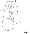
- Fig. 3 shows a second embodiment of a Entgratungsmaschine invention, which differs from the in the Fig. 1 and 2 illustrated first embodiment differs in that the pressure belt 5 ' is guided both to the contact roller 3 ', and about the tension roller 8' and that the tensioning device 6 'acts on the pressure belt 5' from the outside.
- the advantages described for the aforementioned embodiments apply to the in Fig. 3 described embodiment in an analogous manner.
- the sanding belt machine described here combines the advantage of a high compliance with high back pressure with the advantage that the hardness of the contact roller can be adjusted easily and quickly, at least without the contact roller needs to be changed.
- a third embodiment of a deburring machine according to the invention is shown, which differs from the in the Fig. 1 and 2 only differs in that in the third embodiment, the resilient covering instead of the contact roller 3 is now attached to the pressure belt 5 "Again, the resilient coating either soft with a Shore hardness between 5 ° and 25 ° Shore or medium hard with Shore hardness between 60 ° and 70 ° Shore can be used.
- the resilient covering of the middle layer 4 may be formed of EPDM, PVC, PU, rubber or sponge rubber.
- a fourth, preferred embodiment is shown, which differs from the previous embodiments in that on the contact roller 3 a resilient covering 4a '"is provided, while the pressure belt 5"', analogous to the pressure belt 5 "according to the third embodiment, three-layered is, with a soft middle layer 4b "'.
- resilient pad 4a '" attached to the contact roller 3 resilient pad 4a '" has an average hardness of 60 ° to 70 ° Shore preferably 65 ° Shore, while the about 20 mm thick center layer 4b'" of the printing tape 5 "'is kept soft with a hardness of 5 ° to 25 ° Shore, preferably 25 ° Shore
- the inner layer 12 '" is made of a tensile fabric tape with a textured surface and the outer layer 11'" is made of a PVC having a Shore hardness of about 90 ° Shore.
Landscapes
- Engineering & Computer Science (AREA)
- Mechanical Engineering (AREA)
- Finish Polishing, Edge Sharpening, And Grinding By Specific Grinding Devices (AREA)
Description
Die vorliegende Erfindung betrifft Entgratungsmaschinen zum Entgraten von metallenen Werkstücken gemäß den Oberbegriffen der Ansprüche 1 und 3. Aus der
Der auf die Kontaktrolle aufvulkanisierte, gummiartige Belag wird den jeweiligen technischen Anforderungen entsprechend ausgelegt, wobei ein bis zu 30 mm dicker Belag mit einer Shorehärte von 30° Shore bis 70° Shore üblich ist. Beim Entgraten eines Werkstückes ist folgendes zu beachten:
- Mit einem relativ harten Belag von 50° Shore bis 70° Shore kann ein vergleichsweise großer Gegendruck aufgebaut werden, denn die Nachgiebigkeit des harten Belages ist gering. Dabei wird die Kontaktrolle in der Regel in der Höhe so eingestellt, dass das Schleifbandniveau etwas tiefer liegt, als die Oberfläche des Werkstückes, sodass das Schleifband an einer Kante des Werkstückes angreift mit der Folge, dass beim Schleifen im Bereich neben der Kante auch der Grat erfasst wird. Wegen der geringen Nachgiebigkeit wird ein hoher Anpressdruck erreicht, was zu einem hohen Abtrag am Grat führt.
- With a relatively hard coating from 50 ° Shore to 70 ° Shore, a comparatively large back pressure can be built up, because the resilience of the hard coating is low. The contact roller is usually adjusted in height so that the sanding belt level is slightly lower than the surface of the workpiece, so that the sanding belt on an edge of the workpiece attacks with the result that when grinding in the area next to the edge and the burr is detected. Due to the low flexibility, a high contact pressure is achieved, which leads to a high removal on the ridge.
Gleichzeitig ist der Anpressdruck an anderen Stellen, insbesondere an Flächen des Werkstückes, entsprechend geringer und der Abtrag auf der Oberfläche entsprechend niedriger. Das ist auch so gewollt, denn das Werkstück soll entgratet werden.At the same time, the contact pressure at other locations, in particular on surfaces of the workpiece, is correspondingly lower and the removal on the surface correspondingly lower. That is also wanted, because the workpiece should be deburred.
Dabei ist zu berücksichtigen, dass schon bei einer zusätzlichen Zustellung von nur 1/10 mm bis 2/10 mm der Leistungsbedarf der Entgratungsmaschine, der Abtrag und die Wärmeentwicklung deutlich steigen. Derart harte Kontaktrollen werden vorteilhaft bei Werkstücken eingesetzt, welche mittels Laser- oder Wasserstrahltechnik angefertigt wurden, weil diese Werkstücke über die gesamte Werkstückfläche vergleichsweise gleich dick sind.It should be noted that even with an additional delivery of only 1/10 mm to 2/10 mm, the power requirements of the deburring machine, the removal and the heat development increase significantly. Such hard contact rollers are advantageously used for workpieces that were made by laser or water jet technology, because these workpieces are comparatively thick over the entire workpiece surface.
Insbesondere bei Werkstücken, die mittels Plasmaschneiden oder Autogenschneidanlagen hergestellt wurden, kann das Werkstück aufgrund thermischer Beeinflussung verzogen sein. In diesem Fall muss das Schleifband während des Entgratens nachgiebig ausgeführt sein, damit das Schleifband der Kontur des Werkstückes zumindest teilweise folgen kann und die Bearbeitung der Oberfläche des Werkstückes auf ein Minimum reduziert wird, denn eine unnötige Bearbeitung des Werkstückes, insbesondere dessen Oberfläche, erfordert einen hohen Leistungsbedarf der Entgratungsmaschine, führt zu einem hohen Verschleiß des Schleifbandes und hat eine hohe thermische Belastung des Werkstückes zur Folge, was im Extremfall zu weiterem Verzug des Werkstückes führen kann.Particularly in the case of workpieces which have been produced by means of plasma cutting or oxy-fuel cutting plants, the workpiece may be warped due to thermal influences. In this case, the abrasive belt must be made yielding during deburring, so that the grinding belt can follow the contour of the workpiece at least partially and the machining of the surface of the workpiece is reduced to a minimum, because an unnecessary processing of the workpiece, in particular its surface requires one high power requirement of the deburring machine, leading to high wear of the grinding belt and has a high thermal stress on the workpiece result, which in extreme cases can lead to further distortion of the workpiece.
Aus diesem Grund werden bei mittels Plasmaschneiden oder Autogenschneiden angefertigten Werkstücken eher weichere Belege im Bereich 30° Shore bis 40° Shore zum Entgraten eingesetzt, weil Kontaktrollen mit einem derart weichen Belag Toleranzen bis zu 5/10 mm ausgleichen können. Weil die bekannten Vulkanisierungsverfahren keine weicheren Härten zulassen, werden die Gummierungen häufig spiralförmig oder rautenförmig genutet, um den Belag der Kontaktrolle weicher zu gestalten.For this reason, workpieces manufactured using plasma cutting or oxy-fuel cutting tend to use softer documents in the 30 ° shore to 40 ° shore range for deburring, because contact rollers with such a soft coating can compensate for tolerances of up to 5/10 mm. Because the known vulcanization processes do not allow for softer hardnesses, the gummings are often serrated in a spiral or diamond shape to soften the surface of the contact roller.
Bei einem weicheren Belag und damit verbundenem geringeren Gegendruck kann es aber passieren, dass hohe oder spitze Grate aufgrund des fehlenden Gegendruckes das Schleifband durchstoßen und somit beschädigen. Analoges gilt auch, wenn der Grat auf eine Nut in der Gummierung trifft.With a softer covering and the associated lower back pressure, it can happen that high or pointed burrs pierce the sanding belt due to the lack of back pressure and thus to damage. The same applies if the burr meets a groove in the rubber coating.
Zur Lösung dieses Problems wird in der
Um die für das jeweilige Werkstück erforderliche Härte zu erreichen, muss bei einem Werkstückwechsel auch die Folie zusammen mit dem Schleifbogen gewechselt werden, was sehr aufwendig ist. Für den Fall, dass eine andere Nachgiebigkeit bei dem neuen Werkstück erforderlich ist, muss sogar eine andere Kontaktrolle mit einem anderen Belag eingesetzt werden, was ebenfalls sehr aufwendig ist. Ebenso gestaltet sich der Schleifbogenwechsel als sehr aufwendig.In order to achieve the hardness required for the respective workpiece, the film must be changed together with the grinding arc at a workpiece change, which is very expensive. In the event that another compliance with the new workpiece is required, even another contact roller with a different coating must be used, which is also very expensive. Likewise, the grinding arc change designed as very expensive.
Aus der
Eine derartige Kontaktscheibe ist für einen bestimmten Einsatzbereich geeignet. Werden nun auf der Entratungsmaschine andere Werkstücke mit einer anderen Entgratungsanforderung entgratet, so muss eine andere Härte realisiert werden.
Um die für das jeweilige Werkstück erforderliche Härte zu erreichen, muss bei einem Werkstückwechsel auch der Mantel gewechselt werden, was sehr aufwendig ist. Für den Fall, dass eine andere Nachgiebigkeit bei dem neuen Werkstück erforderlich ist, muss sogar eine andere Kontaktrolle mit einem anderen Belag eingesetzt werden, was ebenfalls sehr aufwendig ist. Davon ausgehend liegt der vorliegenden Erfindung die Aufgabe zugrunde, eine Entgratungsmaschine der eingangs genannten Art mit einem großen Nachgiebigkeitsbereich bei zum Entgraten ausreichenden Gegendruck am Grat zu schaffen, deren Handhabung sehr viel einfacher ist.Such a contact disk is suitable for a particular application. Will now on the Entratungsmaschine other workpieces with deburred to another Entgratungsanforderung, so a different hardness must be realized.
In order to achieve the hardness required for the respective workpiece, the shell must be changed at a workpiece change, which is very expensive. In the event that another compliance with the new workpiece is required, even another contact roller with a different coating must be used, which is also very expensive. Based on this, the present invention seeks to provide a deburring machine of the type mentioned above with a large compliance range at sufficient for deburring back pressure on the ridge, their handling is much easier.
Als technische Lösung dieser Aufgabe werden erfingdungsgemäß Entgratungsmaschinen zum Entgraten von metallenen Werkstücken mit den Merkmalen des Anspruches 1 bzw. des Anspruches 3 vorgeschlagen. Vorteilhafte Weiterbildungen dieser Entgratungsmaschinen sind den Unteransprüchen zu entnehmen. Eine nach dieser technischen Lehre ausgebildete Entgratungsmaschine hat den Vorteil, dass durch das zusätzlich zu dem umlaufenden Schleifband vorhandene umlaufende Druckband, insbesondere, wenn dieses eine höhere Härte als der nachgiebige Belag aufweist, am Grat ein vergleichsweise hoher Gegendruck aufgebaut wird, um diesen wirkungsvoll abzuschleifen. Dies ermöglicht den Einsatz eines weicheren Belages, so dass die Nachgiebigkeit erhöht wird, um beispielsweise Werkstückungleichmäßigkeiten besser auszugleichen.
Ein weiterer Vorteil besteht darin, dass durch das vergleichsweise harte Druckband und dem damit verbundenen Gegendruck am Grat eine Beschädigung des Schleifbandes durch spitze oder besonders hervorstehende Grate vermieden wird.As a technical solution to this problem, according to the invention deburring machines for deburring metal workpieces with the features of
Another advantage is that due to the comparatively hard pressure belt and the associated back pressure on the ridge a Damage to the sanding belt is avoided by sharp or protruding burrs.
Ein ganz besonderer Vorteil besteht darin, dass zum Tausch des Druckbandes lediglich die Spannrolle des Schleifbandes, gegebenenfalls auch noch die Spannvorrichtung des Druckbandes, gelöst werden brauchen, bevor das Druckband entnommen und durch ein anderes ersetzt werden kann. Eine Entnahme der schweren Kontaktrolle wie in der
In einer bevorzugten Ausführungsform wird das Druckband über eine eigene Spannvorrichtung gespannt. Dies hat den Vorteil, dass das Druckband unabhängig vom Schleifband gespannt werden kann mit der Folge, das sowohl das Druckband, als auch das Schleifband bestmöglich gespannt werden um Schlupf an der Kontaktrolle zu vermeiden.In a preferred embodiment, the printing tape is stretched over its own tensioning device. This has the advantage that the printing tape can be stretched independently of the sanding belt, with the result that both the printing belt and the sanding belt are optimally tensioned in order to avoid slippage on the contact roller.
In einer anderen, bevorzugten Ausführungsform wird das Druckband derart gespannt, dass das Druckband während des Schleifvorganges einen Anpressdruck auf den auf der Kontaktrolle befindlichen Belag ausübt. Dies hat den Vorteil, dass hierdurch die Härte des Belages in einfacher Weise eingestellt werden kann, ohne dass ein aufwendiger Wechsel der Kontaktrolle und/oder des Druckbandes erforderlich ist. Somit können verschiedene Werkstücke bearbeitet werden, ohne dass das Druckband gewechselt werden braucht.In another preferred embodiment, the printing tape is tensioned so that the printing tape during the grinding process exerts a contact pressure on the pad roller located on the pad. This has the advantage that in this way the hardness of the coating can be adjusted in a simple manner, without a complicated change of the contact roller and / or the printing tape is required. Thus, different workpieces can be edited without the pressure belt needs to be changed.
Verstärkt wird dieser Effekt dadurch, dass auch das Schleifband entsprechend stärker gespannt werden kann und somit der Druck auf den Belag weiter erhöht werden kann.This effect is reinforced by the fact that the sanding belt can be tensioned accordingly more and thus the pressure on the pad can be further increased.
In einer vorteilhaften Ausgestaltung ist das Druckband mindestens genau so breit ausgeführt, wie das Schleifband. Dies hat den Vorteil, dass der gewünschte Gegendruck über die gesamte Breite des Schleifbandes zur Verfügung steht.In an advantageous embodiment, the printing tape is at least as wide designed as the abrasive belt. This has the advantage that the desired back pressure over the entire width of the sanding belt is available.
Der Einsatz eines Druckbandes führt auch dazu, dass ein weicherer Belag eingesetzt werden kann, der eine hohe Nachgiebigkeit aufweist, während der durch das Druckband in Verbindung mit dem Schleifband aufgebaute Gegendruck einen ausreichenden Abtrag des Spanes oder Grates ermöglicht, ohne dass das Schleifband beschädigt wird. Folglich kann sogar ein Belag aus einem Schaumstoff, insbesondere einem technischen Zellschaumstoff, vorzugsweise aus Ethylen-Propylen-Dien-Kautschuk (EPDM), Naturkautschuk, Moosgummi oder Schwammgummi mit einer Härte von 5° Shore bis 25° Shore eingesetzt werden, ohne dass das Schleifband Schaden nimmt, so dass beim Schleifen Nachgiebigkeiten von bis zu 15 mm, im Extremfall sogar 20 mm, erreicht werden können.The use of a pressure belt also means that a softer surface can be used, which has a high compliance, while the built-up by the pressure belt in conjunction with the sanding belt back pressure allows sufficient removal of the chip or burr without the sanding belt is damaged. Consequently, even a covering of a foam, in particular a technical cell foam, preferably of ethylene-propylene-diene rubber (EPDM), natural rubber, sponge rubber or sponge rubber with a hardness of 5 ° Shore to 25 ° Shore can be used without the abrasive belt Damage decreases, so that loops of up to 15 mm, in extreme cases even 20 mm, can be achieved during grinding.
In einer anderen, besonders bevorzugten Ausführungsform, hat die Kontaktrolle einen Durchmesser von 250 mm bis 600 mm, vorzugsweise von 400 mm. Derzeit üblich sind Kontaktrollen mit einem Durchmesser von 180 mm. Eine solch vergrößerte Kontaktrolle hat den Vorteil, das hierdurch die am Grat wirkende Schleiffläche vergrößert wird, mit der Folge, dass der Grat entsprechend länger bearbeitet wird und dass somit eine Entfernung des Grats und sogar eine Verrundung der Kante zuverlässig erreicht wird.In another, particularly preferred embodiment, the contact roller has a diameter of 250 mm to 600 mm, preferably 400 mm. At present, contact rolls with a diameter of 180 mm are common. Such an enlarged contact roller has the advantage of enlarging the grinding surface on the burr, with the result that the burr is correspondingly longer machined and thus reliable removal of the burr and even a rounding of the edge is achieved.
In noch einer anderen, bevorzugten Ausführungsform weist das Druckband an seiner dem Belag der Kontaktrolle zugewandten Seite eine strukturierte Oberfläche auf. Insbesondere, wenn diese strukturierte Oberfläche eine Strukturtiefe von 0,1 mm bis 2 mm aufweist, hat dies den Vorteil, dass sich vorstehende Teile der strukturierten Oberfläche in den vergleichsweise weichen Belag eindrücken und dass somit zwischen dem Druckband und der Kontaktrolle ein Formenschluss entsteht, sodass eine gute Kraftübertragung von der Kontaktrolle auf das Druckband erfolgt und somit der Schlupf minimiert wird.In yet another preferred embodiment, the pressure band has a structured surface on its side facing the lining of the contact roller. In particular, when this structured surface has a structural depth of 0.1 mm to 2 mm, this has the advantage that protruding parts of the structured surface press into the comparatively soft coating and thus between the pressure band and the contact roller forms a positive fit, so that a good power transmission from the contact roller on the printing tape is carried out and thus the slip is minimized.
In einer besonders bevorzugten Ausführungsform ist auf der Kontaktrolle ein nachgiebiger Belag mit einer mittleren Härte zwischen 60° Shore und 70° Shore , vorzugsweise 65° Shore, vorgesehen während das Druckband 5" dreilagig aufgebaut ist, mit einer inneren Lage (der Kontaktrolle zugewandt) aus einem die Zugkräfte aufnehmenden Gewebeband, mit einer Mittellage aus einem weichen nachgiebigen Belag mit einer Härte von 5° Shore bis 25° Shore, vorzugsweise 25° Shore, und mit einer äußeren Lage (dem Schleifband zugewandt) aus einer härteren Schicht mit 80° Shore bis 100° Shore, vorzugsweise 90° Shore. Dies hat den Vorteil, dass unter anderem aufgrund des weichen Belages im Druckband das Entgraten des Werkstückes sehr gut durchführbar ist.In a particularly preferred embodiment, a resilient covering with an average hardness of between 60 ° Shore and 70 ° Shore, preferably 65 ° Shore, is provided on the contact roller while the
Ein weiterer Vorteil besteht darin, dass nach dem Entfernen des Druckbandes eine Kontaktrolle mit einer mittleren Härte von circa 65° Shore zur Verfügung steht, mit der dann ein Schliffbild erstellt werden kann, welches mit einem weichen System nicht möglich ist. Somit können auf ein und derselben Entgratungsmaschine verschiedene Arbeitsgänge absolviert werden, was den Einsatzbereich der Entratungsmaschine deutlich erhöht.Another advantage is that after removal of the printing tape a contact roller with an average hardness of about 65 ° Shore is available, with which then a microsection can be created, which is not possible with a soft system. Thus, different operations can be completed on one and the same Entgratungsmaschine, which significantly increases the application of the Entratungsmaschine.
Weitere Vorteile der erfindungsgemäßen Entgratungsmaschine ergeben sich aus der beigefügten Zeichnung und den nachstehend beschriebenen Ausführungsformen. Die erwähnten Ausführungsformen sind nicht als abschließende Aufzählung zu verstehen, sondern haben vielmehr beispielhaften Charakter. Es zeigen:
- Fig. 1
- eine schematische dargestellte Prinzipskizze einer ersten Ausführungsform einer erfindungsgemäßen Entgratungsmaschine;
- Fig. 2
- eine im Querschnitt dargestellte Ausschnittsvergrößerung eines Druckbandes der Entgratungsmaschine nach
Fig. 1 , gemäß Linie II inFig. 1 ; - Fig. 3
- eine schematisch dargestellte Prinzipskizze einer zweiten Ausführungsform einer erfindungsgemäßen Entgratungsmaschine.
- Fig. 4
- eine schematische dargestellte Prinzipskizze einer dritten Ausführungsform einer erfindungsgemäßen Entgratungsmaschine;
- Fig. 5
- eine im Querschnitt dargestellte Ausschnittsvergrößerung eines Druckbandes der Entgratungsmaschine nach
Fig. 4 , gemäß Linie V inFig. 4 ; - Fig. 6
- eine schematische dargestellte Prinzipskizze einer vierten Ausführungsform einer erfindungsgemäßen Entgratungsmaschine;
- Fig. 7
- eine im Querschnitt dargestellte Ausschnittsvergrößerung eines Druckbandes der Entgratungsmaschine nach
Fig. 6 , gemäß Linie VII inFig. 6 .
- Fig. 1
- a schematic illustrated schematic diagram of a first embodiment of a deburring machine according to the invention;
- Fig. 2
- an enlarged detail of a printing tape of the deburring machine shown in cross section
Fig. 1 , according to line II inFig. 1 ; - Fig. 3
- a schematically illustrated schematic diagram of a second embodiment of a deburring machine according to the invention.
- Fig. 4
- a schematic illustrated schematic diagram of a third embodiment of a deburring machine according to the invention;
- Fig. 5
- an enlarged detail of a printing tape of the deburring machine shown in cross section
Fig. 4 , according to line V inFig. 4 ; - Fig. 6
- a schematic illustrated schematic diagram of a fourth embodiment of a deburring machine according to the invention;
- Fig. 7
- an enlarged detail of a printing tape of the deburring machine shown in cross section
Fig. 6 , according to line VII inFig. 6 ,
In den
Die Spannvorrichtung 6 umfasst eine koaxial zur Kontaktrolle 3 ausgerichtete Rolle 9, welche über an sich bekannte Federmechanismen 10 gespannt wird. Analog hierzu ist auch die Spannrolle 8 aufgebaut. Das Druckband 5 verläuft einerseits um die Kontaktrolle 3 und andererseits um die Rolle 9 um, wobei die Spannvorrichtung 6 die Rolle 9 bewegt, um das Druckband 5 zu spannen.The
Der aus EPDM auf der Kontaktrolle 3 aufgebrachte Belag 4 hat in der hier dargestellten Ausführungsform eine Dicke von circa 20 mm und besitzt eine Härte von 15° Shore. Auch wäre es denkbar, den Belag mit einer Härte von nur 5° Shore oder von bis zu 25° Shore auszustatten. Die Dicke des Belages kann zwischen 5 mm und 50 mm variieren.In the embodiment shown here, the
Das Druckband 5 ist zweilagig aufgebaut und besitzt auf seiner dem Schleifband 7 zugewandten, äußeren Seite eine vergleichsweise harte Schicht 11 aus PVC, während die der Kontaktrolle 3 zugewandte, innere Seite des Druckbandes 5 aus einem zugfesten Gewebe 12 mit einer strukturierten Oberfläche gebildet ist. Die Härte der PVC-Schicht 11 ist ungefähr um Faktor 5,33 höher als die Härte des Belages 4 und beträgt 80° Shore. In anderen Ausführungsformen, insbesondere bei einer Härte des Belages von 5° Shore, kann die PVC-Schicht auch um den Faktor 16 härter sein.The
Es ist möglich, das Druckband 5 über die Spannvorrichtung 9 so stark zu spannen, dass der Belag 4 während des eigentlichen Schleifvorganges ein Stück weit zusammengedrückt wird, so dass der Belag 4 während des Schleifvorganges eine höhere Härte aufweist. Hierdurch ist es möglich, mit der selben Entgratungsmaschine verschiedene Härten einzustellen, ohne dass die Kontaktrolle bzw. ohne dass der Belag gewechselt werden braucht.It is possible to stretch the
Während des Schleifvorganges drückt sich die strukturierte Oberfläche des Gewebebandes 12 des Druckbandes 5 zumindest teilweise in den Belag 4 ein, sodass über diesen Formschluss eine gute Kraftübertragung der elektrisch angetriebenen Kontaktrolle 3 auf das Druckband 5 erfolgt. Dabei wird das um das Druckband 5 umlaufende Schleifband 7 über die Spannrolle 8 so angespannt, dass der Schlupf zwischen dem Druckband 5 und dem Schleifband 7 auf ein Minimum reduziert wird, sodass die elektrisch angetriebene Kontaktrolle 3 das Schleifband 7 zuverlässig und quasi ohne Schlupf antreibt.During the grinding process, the structured surface of the
Zum Bearbeiten des Werkstückes 2 wird die Kontaktrolle 3 so eingestellt, dass der tiefste Punkt des Schleifbandes 7 unterhalb der Oberkante des Werkstücks 2 liegt. Gelangt nun das Werkstück 2 unter die Kontaktrolle 3, so übt das Schleifband 7 unterstützt durch das Druckband 5 und den Belag 4 eine Kraft auf den am Werkstück 2 vorstehenden, hier nicht dargestellten Grat, aus, und schleift diesen ab. Weil die Kontaktrolle 3 einen Durchmesser von 400 mm aufweist, steht eine vergleichsweise lange Bearbeitungszeit zur Verfügung, so dass der Grat zuverlässig entfernt wird. Für den Fall, dass das Werkstück Unebenheiten oder einen Verzug aufweist, ist die Schleifbandmaschine aufgrund des weichen und 20 mm dicken Belages 4 in der Lage, einige mm, insbesondere bis zu 10 mm, nachzugeben, um der Kontur des Werkstücks zu folgen. Durch die vergleichsweise harte PVC-Schicht 11 des Druckbandes 5 wird am Grat des Werkstücks 2 ein ausreichend hoher Gegendruck aufgebaut, sodass der Grat das Schleifband 7 nicht beschädigt.For machining the
Soll ein anderes Werkstück bearbeitet werden, insbesondere ein Werkstück mit weniger Unebenheiten oder weniger Verzug, so besteht die Möglichkeit, während des Schleifvorganges, die wirksame Härte zu erhöhen, in dem über die Spannvorrichtung 9 die Spannkraft am Druckband 5 erhöht wird. Hierdurch wird der Belag 4 im Kontaktbereich zum Werkstück zusammengedrückt wird mit der Folge, dass hierdurch eine größere Härte erreicht wird. Dementsprechend muss die Spannrolle 8 nachgestellt werden, damit zwischen dem Druckband 5 und dem Schleifband 7 kein Schlupf entsteht. Mit dieser nunmehr härter eingestellten Schleifbandmaschine ist es möglich, größere Grate zu bearbeiten oder die Grate schneller zu bearbeiten.If another workpiece is to be machined, in particular a workpiece with less unevenness or less distortion, it is possible to increase the effective hardness during the grinding process by increasing the clamping force on the
Sollte ein Werkstück mit viel Verzug und hohem Grat bearbeitet werden, kann durch den Einsatz eines dickeren und härteren Druckbandes bei gleichzeitig geringerem Spanndruck auf dem Druckband der ,Schleifdruck am Grat erhöht werden und gleichzeitig die Nachgiebigkeit zur Kompensation von Werkstücktoleranzen erhalten werden.If a workpiece is processed with a lot of distortion and a high burr, the use of a thicker and harder pressure belt with a lower clamping pressure on the printing belt can increase the grinding pressure on the burr and at the same time preserve the flexibility to compensate for workpiece tolerances.
In einer hier nicht dargestellten Ausführungsform wird ein nachgiebiger Belag 4 mit einer etwas höheren Härte von 60° Shore bis 70° Shore, vorzugsweise 65° Shore eingesetzt. Damit kann auf dem Werkstück 2 ein anderes Schleifbild als mit dem weichen Belag mit 15° Shore erstellt werden.In an embodiment not shown here, a
In einer ganz anderen, hier nicht dargestellten Ausführungsform ist zwischen der Kontaktrolle und der Spannrolle einerseits und dem Schleifband andererseits ein Druckband vorgesehen, wobei sowohl das Druckband, als auch das Schleifband von dergleichen Spannrolle gespannt werden. Auch hier führt das Druckband zu einem erhöhten Gegendruck am Grat und ermöglicht den Einsatz eines weicheren Belages mit dem Vorteil einer höheren Nachgiebigkeit, bei gleichzeitig einfacher Handhabung beim Wechsel des Druckbandes und/oder des Schleifbandes.In a completely different, not shown embodiment, a pressure band is provided between the contact roller and the tension roller on the one hand and the abrasive belt on the other hand, wherein both the pressure belt, and the sanding belt are tensioned by the like tensioner. Again, the pressure belt leads to an increased back pressure on the ridge and allows the use of a softer surface with the advantage of a higher compliance, at the same time easy to handle when changing the pressure belt and / or the sanding belt.
Somit vereint die hier beschriebene Schleifbandmaschine den Vorteil einer hohen Nachgiebigkeit bei gleichzeitig hohem Gegendruck mit dem Vorteil, dass die Härte an der Kontaktrolle in einfacher Weise und schnell eingestellt werden kann, jedenfalls ohne dass die Kontaktrolle gewechselt werden braucht.Thus, the sanding belt machine described here combines the advantage of a high compliance with high back pressure with the advantage that the hardness of the contact roller can be adjusted easily and quickly, at least without the contact roller needs to be changed.
In den
Wie insbesondere aus
In dieser Ausführungsform kann der nachgiebige Belag der Mittellage 4" aus EPDM, PVC, PU, Gummi oder Moosgummi gebildet sein.In this embodiment, the resilient covering of the
In den
In dieser Ausführungsform kann durch den vergleichsweise einfachen Ausbau des Druckbandes und durch den Einbau eines Druckbandes mit einer anderen Härte schnell und kostengünstig fast jede beliebige Härte bereitgestellt werden, so dass die Entgratungsmaschine zum Entgraten vieler verschiedener Werkstücke eingesetzt werden kann.In this embodiment, by the relatively simple removal of the printing tape and by the installation of a pressure belt with a different hardness almost any hardness can be provided quickly and inexpensively, so that the deburring machine can be used for deburring many different workpieces.
Claims (14)
- A deburring machine for deburring metal work pieces with a continuous circulating abrasive belt (7, 7'), with a contact roller (3) for pressing the abrasive belt (7, 7') against the work piece (2), wherein the contact roller (3) is surrounded by a resilient coating (4, 4a"'), and with a tensioning roller (8) for tensioning the abrasive belt (7, 7'),
characterized in that
a pressure belt (5, 5', 5", 5"') circulating continuously around the contact roller (3) and a second roller (9) is provided between the contact roller (3) and the abrasive belt (7, 7'). - The deburring machine according to claim 1,
characterized in that
the pressure belt (5, 5') is designed so that it is harder than the resilient coating (4) of the contact roller (3), in particular that the hardness of the pressure belt (5) is higher than the hardness of the resilient coating (4) by a factor of 2 to 10 preferably by a factor of 3 to 6. - A deburring machine for deburring metal work pieces with a continuously circulating abrasive belt (7), with a contact roller (3) for pressing the abrasive belt (7) against the work piece (2) and with a tensioning roller (8) for tensioning the abrasive belt (7),
characterized in that
a pressure belt (5", 5"') circulating continuously around the contact roller (3) and a second roller (9) is provided between the contact roller (3) and the abrasive belt (7) and that the pressure belt (5", 5'") has a resilient coating. - The deburring machine according to one of the afore-mentioned claims,
characterized in that
the pressure belt (5", 5'") is designed with at least three layers, with an inner stretch-resistant layer (12", 12'"), with a middle layer (4", 4b'") made of a soft resilient coating and with a harder outer layer (11", 11'"). - The deburring machine according to one of the afore-mentioned claims,
characterized in that
the resilient coating (4) has a hardness of 5° Shore to 25° Shore, preferably of 20° Shore. - The deburring machine according to claim 4,
characterized in that
the middle layer (4") has a hardness of 5° Shore to 25° Shore, preferably of 20° Shore. - The deburring machine according to one of the afore-mentioned claims,
characterized in that
the resilient coating (4a") has a hardness of 60° Shore to 70° Shore, preferably of 65° Shore. - The deburring machine according to claim 4,
characterized in that
the middle layer (4b"') has a hardness of 5° Shore to 25° Shore, preferably of 20° Shore. - The deburring machine according to one of the afore-mentioned claims,
characterized in that
the resilient coating (4, 4a'") and/or the middle layer (4", 4b"') is made of a foam material, in particular of a technical cellular foam material, preferably of ethylene propylene diene monomer rubber (EPDM), natural rubber, foamed rubber or sponge rubber. - The deburring machine according to one of the afore-mentioned claims,
characterized in that
the pressure belt (5, 5', 5"') is tensioned in such a manner that the pressure belt (5, 5', 5"') exerts a contact pressure onto the resilient coating (4, 4a") during the grinding process. - The deburring machine according to one of the afore-mentioned claims,
characterized in that
the pressure belt (5, 5', 5', 5'") is designed so that it has at least exactly the same width as the abrasive belt (6). - The deburring machine according to one of the afore-mentioned claims,
characterized in that
the pressure belt (5, 5', 5", 5'") has a structured surface on its side oriented toward the contact roller (3). - The deburring machine according to claim 12,
characterized in that
the structured surface has a structure depth of 0.1 mm to 2 mm. - The deburring machine according to one of the claims 12 or 13,
characterized in that
the structured surface has elevations, in particular lumps, and/or recesses, in particular grooves.
Priority Applications (1)
| Application Number | Priority Date | Filing Date | Title |
|---|---|---|---|
| US15/072,447 US20160325395A1 (en) | 2015-05-07 | 2016-03-17 | Deburring Machine for Deburring Metal Work Pieces |
Applications Claiming Priority (1)
| Application Number | Priority Date | Filing Date | Title |
|---|---|---|---|
| DE102015005915.7A DE102015005915A1 (en) | 2015-05-07 | 2015-05-07 | Deburring machine for deburring metal workpieces |
Publications (2)
| Publication Number | Publication Date |
|---|---|
| EP3103587A1 EP3103587A1 (en) | 2016-12-14 |
| EP3103587B1 true EP3103587B1 (en) | 2017-06-14 |
Family
ID=55236158
Family Applications (1)
| Application Number | Title | Priority Date | Filing Date |
|---|---|---|---|
| EP16000170.7A Active EP3103587B1 (en) | 2015-05-07 | 2016-01-25 | Deburring machine for deburring metallic workpieces |
Country Status (3)
| Country | Link |
|---|---|
| EP (1) | EP3103587B1 (en) |
| DE (1) | DE102015005915A1 (en) |
| PT (1) | PT3103587T (en) |
Families Citing this family (2)
| Publication number | Priority date | Publication date | Assignee | Title |
|---|---|---|---|---|
| CN111571349A (en) * | 2020-04-28 | 2020-08-25 | 青岛迪普瑞机械有限公司 | Dry type frosting and deburring machine for plates |
| CN114800188B (en) * | 2022-04-22 | 2023-07-18 | 浙江亚特电器股份有限公司 | But quick assembly disassembly's electronic abrasive band machine |
Family Cites Families (6)
| Publication number | Priority date | Publication date | Assignee | Title |
|---|---|---|---|---|
| DE1042416B (en) * | 1954-03-06 | 1958-10-30 | C Hilzinger Thum Fa | Contact disc for belt grinders |
| DD132181B1 (en) * | 1977-05-26 | 1981-07-29 | Juergen Kallenbach | BAND GRINDING METHOD FOR REMOVING THE FORGING GRID TO ROHLINGEN FOR WRENCHES |
| DE3020393A1 (en) * | 1980-05-29 | 1982-01-28 | Friedr. August Picard KG, 5630 Remscheid | Endless band grinder unit - has band supported on resilient endless belt running around support disc with spaced projections on disc surface |
| DE3238624A1 (en) | 1982-10-19 | 1984-04-19 | Paul Dipl.-Ing. 6925 Eschelbronn Ernst Jun. | Grinding roll for a sheet-deburring machine |
| DE10342134B4 (en) * | 2003-09-12 | 2009-09-03 | Thielenhaus Technologies Gmbh | Method and device for finishing crankshafts and camshafts |
| DE202005014430U1 (en) * | 2005-09-12 | 2005-11-24 | Lissmac Maschinenbau Und Diamantwerkzeuge Gmbh | Device for machining strip or plate like metal workpieces has grinding belt which in region of workpiece is in active connection with drive device which then drives the belt |
-
2015
- 2015-05-07 DE DE102015005915.7A patent/DE102015005915A1/en not_active Withdrawn
-
2016
- 2016-01-25 EP EP16000170.7A patent/EP3103587B1/en active Active
- 2016-01-25 PT PT160001707T patent/PT3103587T/en unknown
Non-Patent Citations (1)
| Title |
|---|
| None * |
Also Published As
| Publication number | Publication date |
|---|---|
| DE102015005915A1 (en) | 2016-11-10 |
| EP3103587A1 (en) | 2016-12-14 |
| PT3103587T (en) | 2017-09-05 |
Similar Documents
| Publication | Publication Date | Title |
|---|---|---|
| EP1924403B2 (en) | Device for the machining, by deburring or grinding, of a belt-shaped or plate-shaped metallic workpiece | |
| EP2212058B2 (en) | Pressing device for cutting means and apparatus and method for finishing circumferential surfaces on cylindrical parts of a workpiece | |
| EP3052239B1 (en) | Method for operating a system comprising at least a device having a rotating surface | |
| DE202012002267U1 (en) | Disc grinder of a device for deburring and / or rounding of metal workpieces in a continuous process | |
| EP2087971A2 (en) | Cutting device | |
| EP2504125B1 (en) | Machining station and device for machining a workpiece | |
| DE69906679T2 (en) | Device for tensioning flexible elements wound around rollers | |
| EP3103587B1 (en) | Deburring machine for deburring metallic workpieces | |
| DE60126707T2 (en) | Device for machining cylindrical running surfaces by means of an abrasive belt | |
| EP2527102B1 (en) | Blade and cutting device and cutting method | |
| AT502101A1 (en) | METHOD FOR PROCESSING TREES OF WINTER SPORTS EQUIPMENT | |
| DE2017029C3 (en) | Belt grinder | |
| EP3181293B1 (en) | Finishing tool possessing locally varying cutting ability | |
| DE602004003943T2 (en) | METAL BELTS | |
| DE10239402B4 (en) | Roller grinding apparatus and method for grinding a roller | |
| DE102022108782B3 (en) | Method for force-controlled self-sharpening of at least one cutting element of a machining tool and machining tool | |
| EP1920884B1 (en) | Method for strip finishing of workpiece peripheral surfaces | |
| DE2031717A1 (en) | Belt grinder | |
| DE102008052564A1 (en) | Flow path grinding machine for e.g. deburring of pierced metallic workpiece, has pressing element attached to interior side of endless grinding belts between rollers, and drawing device provided at belts to draw belts against element | |
| AT521312B1 (en) | Device for non-abrasive hardening of rail head surfaces | |
| EP1436121B1 (en) | Method for manufacturing an abrasive element, in particular for bits of hollow drills | |
| DE102014208426B3 (en) | Method for producing a printing plate | |
| CH605034A5 (en) | Machine for chamfering glass sheet lower edge | |
| DE102021001016A1 (en) | Pressure element for a grinding belt with cooling | |
| DE2228623C2 (en) | Machine for splitting leather, hides, sheet or layered products |
Legal Events
| Date | Code | Title | Description |
|---|---|---|---|
| PUAI | Public reference made under article 153(3) epc to a published international application that has entered the european phase |
Free format text: ORIGINAL CODE: 0009012 |
|
| STAA | Information on the status of an ep patent application or granted ep patent |
Free format text: STATUS: THE APPLICATION HAS BEEN PUBLISHED |
|
| AK | Designated contracting states |
Kind code of ref document: A1 Designated state(s): AL AT BE BG CH CY CZ DE DK EE ES FI FR GB GR HR HU IE IS IT LI LT LU LV MC MK MT NL NO PL PT RO RS SE SI SK SM TR |
|
| AX | Request for extension of the european patent |
Extension state: BA ME |
|
| STAA | Information on the status of an ep patent application or granted ep patent |
Free format text: STATUS: REQUEST FOR EXAMINATION WAS MADE |
|
| 17P | Request for examination filed |
Effective date: 20161209 |
|
| RBV | Designated contracting states (corrected) |
Designated state(s): AL AT BE BG CH CY CZ DE DK EE ES FI FR GB GR HR HU IE IS IT LI LT LU LV MC MK MT NL NO PL PT RO RS SE SI SK SM TR |
|
| GRAP | Despatch of communication of intention to grant a patent |
Free format text: ORIGINAL CODE: EPIDOSNIGR1 |
|
| STAA | Information on the status of an ep patent application or granted ep patent |
Free format text: STATUS: GRANT OF PATENT IS INTENDED |
|
| INTG | Intention to grant announced |
Effective date: 20170310 |
|
| GRAS | Grant fee paid |
Free format text: ORIGINAL CODE: EPIDOSNIGR3 |
|
| GRAA | (expected) grant |
Free format text: ORIGINAL CODE: 0009210 |
|
| STAA | Information on the status of an ep patent application or granted ep patent |
Free format text: STATUS: THE PATENT HAS BEEN GRANTED |
|
| AK | Designated contracting states |
Kind code of ref document: B1 Designated state(s): AL AT BE BG CH CY CZ DE DK EE ES FI FR GB GR HR HU IE IS IT LI LT LU LV MC MK MT NL NO PL PT RO RS SE SI SK SM TR |
|
| REG | Reference to a national code |
Ref country code: GB Ref legal event code: FG4D Free format text: NOT ENGLISH |
|
| REG | Reference to a national code |
Ref country code: CH Ref legal event code: EP Ref country code: AT Ref legal event code: REF Ref document number: 900505 Country of ref document: AT Kind code of ref document: T Effective date: 20170615 |
|
| REG | Reference to a national code |
Ref country code: IE Ref legal event code: FG4D Free format text: LANGUAGE OF EP DOCUMENT: GERMAN |
|
| REG | Reference to a national code |
Ref country code: DE Ref legal event code: R096 Ref document number: 502016000034 Country of ref document: DE |
|
| REG | Reference to a national code |
Ref country code: NL Ref legal event code: FP |
|
| REG | Reference to a national code |
Ref country code: PT Ref legal event code: SC4A Ref document number: 3103587 Country of ref document: PT Date of ref document: 20170905 Kind code of ref document: T Free format text: AVAILABILITY OF NATIONAL TRANSLATION Effective date: 20170830 |
|
| REG | Reference to a national code |
Ref country code: LT Ref legal event code: MG4D |
|
| PG25 | Lapsed in a contracting state [announced via postgrant information from national office to epo] |
Ref country code: NO Free format text: LAPSE BECAUSE OF FAILURE TO SUBMIT A TRANSLATION OF THE DESCRIPTION OR TO PAY THE FEE WITHIN THE PRESCRIBED TIME-LIMIT Effective date: 20170914 Ref country code: LT Free format text: LAPSE BECAUSE OF FAILURE TO SUBMIT A TRANSLATION OF THE DESCRIPTION OR TO PAY THE FEE WITHIN THE PRESCRIBED TIME-LIMIT Effective date: 20170614 Ref country code: FI Free format text: LAPSE BECAUSE OF FAILURE TO SUBMIT A TRANSLATION OF THE DESCRIPTION OR TO PAY THE FEE WITHIN THE PRESCRIBED TIME-LIMIT Effective date: 20170614 Ref country code: GR Free format text: LAPSE BECAUSE OF FAILURE TO SUBMIT A TRANSLATION OF THE DESCRIPTION OR TO PAY THE FEE WITHIN THE PRESCRIBED TIME-LIMIT Effective date: 20170915 Ref country code: HR Free format text: LAPSE BECAUSE OF FAILURE TO SUBMIT A TRANSLATION OF THE DESCRIPTION OR TO PAY THE FEE WITHIN THE PRESCRIBED TIME-LIMIT Effective date: 20170614 |
|
| PG25 | Lapsed in a contracting state [announced via postgrant information from national office to epo] |
Ref country code: BG Free format text: LAPSE BECAUSE OF FAILURE TO SUBMIT A TRANSLATION OF THE DESCRIPTION OR TO PAY THE FEE WITHIN THE PRESCRIBED TIME-LIMIT Effective date: 20170914 Ref country code: RS Free format text: LAPSE BECAUSE OF FAILURE TO SUBMIT A TRANSLATION OF THE DESCRIPTION OR TO PAY THE FEE WITHIN THE PRESCRIBED TIME-LIMIT Effective date: 20170614 Ref country code: LV Free format text: LAPSE BECAUSE OF FAILURE TO SUBMIT A TRANSLATION OF THE DESCRIPTION OR TO PAY THE FEE WITHIN THE PRESCRIBED TIME-LIMIT Effective date: 20170614 Ref country code: SE Free format text: LAPSE BECAUSE OF FAILURE TO SUBMIT A TRANSLATION OF THE DESCRIPTION OR TO PAY THE FEE WITHIN THE PRESCRIBED TIME-LIMIT Effective date: 20170614 |
|
| REG | Reference to a national code |
Ref country code: FR Ref legal event code: PLFP Year of fee payment: 3 |
|
| PG25 | Lapsed in a contracting state [announced via postgrant information from national office to epo] |
Ref country code: EE Free format text: LAPSE BECAUSE OF FAILURE TO SUBMIT A TRANSLATION OF THE DESCRIPTION OR TO PAY THE FEE WITHIN THE PRESCRIBED TIME-LIMIT Effective date: 20170614 Ref country code: CZ Free format text: LAPSE BECAUSE OF FAILURE TO SUBMIT A TRANSLATION OF THE DESCRIPTION OR TO PAY THE FEE WITHIN THE PRESCRIBED TIME-LIMIT Effective date: 20170614 Ref country code: SK Free format text: LAPSE BECAUSE OF FAILURE TO SUBMIT A TRANSLATION OF THE DESCRIPTION OR TO PAY THE FEE WITHIN THE PRESCRIBED TIME-LIMIT Effective date: 20170614 |
|
| PG25 | Lapsed in a contracting state [announced via postgrant information from national office to epo] |
Ref country code: SM Free format text: LAPSE BECAUSE OF FAILURE TO SUBMIT A TRANSLATION OF THE DESCRIPTION OR TO PAY THE FEE WITHIN THE PRESCRIBED TIME-LIMIT Effective date: 20170614 Ref country code: PL Free format text: LAPSE BECAUSE OF FAILURE TO SUBMIT A TRANSLATION OF THE DESCRIPTION OR TO PAY THE FEE WITHIN THE PRESCRIBED TIME-LIMIT Effective date: 20170614 Ref country code: ES Free format text: LAPSE BECAUSE OF FAILURE TO SUBMIT A TRANSLATION OF THE DESCRIPTION OR TO PAY THE FEE WITHIN THE PRESCRIBED TIME-LIMIT Effective date: 20170614 Ref country code: IS Free format text: LAPSE BECAUSE OF FAILURE TO SUBMIT A TRANSLATION OF THE DESCRIPTION OR TO PAY THE FEE WITHIN THE PRESCRIBED TIME-LIMIT Effective date: 20171014 |
|
| REG | Reference to a national code |
Ref country code: DE Ref legal event code: R097 Ref document number: 502016000034 Country of ref document: DE |
|
| PLBE | No opposition filed within time limit |
Free format text: ORIGINAL CODE: 0009261 |
|
| STAA | Information on the status of an ep patent application or granted ep patent |
Free format text: STATUS: NO OPPOSITION FILED WITHIN TIME LIMIT |
|
| PG25 | Lapsed in a contracting state [announced via postgrant information from national office to epo] |
Ref country code: DK Free format text: LAPSE BECAUSE OF FAILURE TO SUBMIT A TRANSLATION OF THE DESCRIPTION OR TO PAY THE FEE WITHIN THE PRESCRIBED TIME-LIMIT Effective date: 20170614 |
|
| 26N | No opposition filed |
Effective date: 20180315 |
|
| PG25 | Lapsed in a contracting state [announced via postgrant information from national office to epo] |
Ref country code: SI Free format text: LAPSE BECAUSE OF FAILURE TO SUBMIT A TRANSLATION OF THE DESCRIPTION OR TO PAY THE FEE WITHIN THE PRESCRIBED TIME-LIMIT Effective date: 20170614 |
|
| PG25 | Lapsed in a contracting state [announced via postgrant information from national office to epo] |
Ref country code: MT Free format text: LAPSE BECAUSE OF FAILURE TO SUBMIT A TRANSLATION OF THE DESCRIPTION OR TO PAY THE FEE WITHIN THE PRESCRIBED TIME-LIMIT Effective date: 20170614 |
|
| PG25 | Lapsed in a contracting state [announced via postgrant information from national office to epo] |
Ref country code: LU Free format text: LAPSE BECAUSE OF NON-PAYMENT OF DUE FEES Effective date: 20180125 |
|
| REG | Reference to a national code |
Ref country code: IE Ref legal event code: MM4A |
|
| PG25 | Lapsed in a contracting state [announced via postgrant information from national office to epo] |
Ref country code: IE Free format text: LAPSE BECAUSE OF NON-PAYMENT OF DUE FEES Effective date: 20180125 |
|
| PG25 | Lapsed in a contracting state [announced via postgrant information from national office to epo] |
Ref country code: MC Free format text: LAPSE BECAUSE OF FAILURE TO SUBMIT A TRANSLATION OF THE DESCRIPTION OR TO PAY THE FEE WITHIN THE PRESCRIBED TIME-LIMIT Effective date: 20170614 |
|
| PG25 | Lapsed in a contracting state [announced via postgrant information from national office to epo] |
Ref country code: TR Free format text: LAPSE BECAUSE OF FAILURE TO SUBMIT A TRANSLATION OF THE DESCRIPTION OR TO PAY THE FEE WITHIN THE PRESCRIBED TIME-LIMIT Effective date: 20170614 |
|
| PG25 | Lapsed in a contracting state [announced via postgrant information from national office to epo] |
Ref country code: MK Free format text: LAPSE BECAUSE OF NON-PAYMENT OF DUE FEES Effective date: 20170614 Ref country code: CY Free format text: LAPSE BECAUSE OF FAILURE TO SUBMIT A TRANSLATION OF THE DESCRIPTION OR TO PAY THE FEE WITHIN THE PRESCRIBED TIME-LIMIT Effective date: 20170614 Ref country code: HU Free format text: LAPSE BECAUSE OF FAILURE TO SUBMIT A TRANSLATION OF THE DESCRIPTION OR TO PAY THE FEE WITHIN THE PRESCRIBED TIME-LIMIT; INVALID AB INITIO Effective date: 20160125 Ref country code: RO Free format text: LAPSE BECAUSE OF FAILURE TO SUBMIT A TRANSLATION OF THE DESCRIPTION OR TO PAY THE FEE WITHIN THE PRESCRIBED TIME-LIMIT Effective date: 20170614 |
|
| PG25 | Lapsed in a contracting state [announced via postgrant information from national office to epo] |
Ref country code: AL Free format text: LAPSE BECAUSE OF FAILURE TO SUBMIT A TRANSLATION OF THE DESCRIPTION OR TO PAY THE FEE WITHIN THE PRESCRIBED TIME-LIMIT Effective date: 20170614 |
|
| PGFP | Annual fee paid to national office [announced via postgrant information from national office to epo] |
Ref country code: FR Payment date: 20210122 Year of fee payment: 6 Ref country code: CH Payment date: 20210120 Year of fee payment: 6 |
|
| PGFP | Annual fee paid to national office [announced via postgrant information from national office to epo] |
Ref country code: AT Payment date: 20210121 Year of fee payment: 6 |
|
| PGFP | Annual fee paid to national office [announced via postgrant information from national office to epo] |
Ref country code: GB Payment date: 20220223 Year of fee payment: 7 |
|
| REG | Reference to a national code |
Ref country code: CH Ref legal event code: PL |
|
| REG | Reference to a national code |
Ref country code: AT Ref legal event code: MM01 Ref document number: 900505 Country of ref document: AT Kind code of ref document: T Effective date: 20220125 |
|
| PG25 | Lapsed in a contracting state [announced via postgrant information from national office to epo] |
Ref country code: AT Free format text: LAPSE BECAUSE OF NON-PAYMENT OF DUE FEES Effective date: 20220125 |
|
| PG25 | Lapsed in a contracting state [announced via postgrant information from national office to epo] |
Ref country code: FR Free format text: LAPSE BECAUSE OF NON-PAYMENT OF DUE FEES Effective date: 20220131 |
|
| PG25 | Lapsed in a contracting state [announced via postgrant information from national office to epo] |
Ref country code: LI Free format text: LAPSE BECAUSE OF NON-PAYMENT OF DUE FEES Effective date: 20220131 Ref country code: CH Free format text: LAPSE BECAUSE OF NON-PAYMENT OF DUE FEES Effective date: 20220131 |
|
| P01 | Opt-out of the competence of the unified patent court (upc) registered |
Effective date: 20230601 |
|
| GBPC | Gb: european patent ceased through non-payment of renewal fee |
Effective date: 20230125 |
|
| PG25 | Lapsed in a contracting state [announced via postgrant information from national office to epo] |
Ref country code: GB Free format text: LAPSE BECAUSE OF NON-PAYMENT OF DUE FEES Effective date: 20230125 |
|
| PGFP | Annual fee paid to national office [announced via postgrant information from national office to epo] |
Ref country code: PT Payment date: 20231221 Year of fee payment: 9 |
|
| PGFP | Annual fee paid to national office [announced via postgrant information from national office to epo] |
Ref country code: NL Payment date: 20240119 Year of fee payment: 9 |
|
| PGFP | Annual fee paid to national office [announced via postgrant information from national office to epo] |
Ref country code: DE Payment date: 20231120 Year of fee payment: 9 |
|
| PGFP | Annual fee paid to national office [announced via postgrant information from national office to epo] |
Ref country code: IT Payment date: 20240129 Year of fee payment: 9 Ref country code: BE Payment date: 20240119 Year of fee payment: 9 |