EP3103579B1 - Fraise de rodage comprenant un moteur electrique - Google Patents
Fraise de rodage comprenant un moteur electrique Download PDFInfo
- Publication number
- EP3103579B1 EP3103579B1 EP16173795.2A EP16173795A EP3103579B1 EP 3103579 B1 EP3103579 B1 EP 3103579B1 EP 16173795 A EP16173795 A EP 16173795A EP 3103579 B1 EP3103579 B1 EP 3103579B1
- Authority
- EP
- European Patent Office
- Prior art keywords
- recording unit
- drive motor
- tip dresser
- current
- milling
- Prior art date
- Legal status (The legal status is an assumption and is not a legal conclusion. Google has not performed a legal analysis and makes no representation as to the accuracy of the status listed.)
- Active
Links
Images

Classifications
-
- B—PERFORMING OPERATIONS; TRANSPORTING
- B23—MACHINE TOOLS; METAL-WORKING NOT OTHERWISE PROVIDED FOR
- B23K—SOLDERING OR UNSOLDERING; WELDING; CLADDING OR PLATING BY SOLDERING OR WELDING; CUTTING BY APPLYING HEAT LOCALLY, e.g. FLAME CUTTING; WORKING BY LASER BEAM
- B23K11/00—Resistance welding; Severing by resistance heating
- B23K11/30—Features relating to electrodes
- B23K11/3063—Electrode maintenance, e.g. cleaning, grinding
-
- B—PERFORMING OPERATIONS; TRANSPORTING
- B23—MACHINE TOOLS; METAL-WORKING NOT OTHERWISE PROVIDED FOR
- B23B—TURNING; BORING
- B23B5/00—Turning-machines or devices specially adapted for particular work; Accessories specially adapted therefor
- B23B5/16—Turning-machines or devices specially adapted for particular work; Accessories specially adapted therefor for bevelling, chamfering, or deburring the ends of bars or tubes
- B23B5/166—Devices for working electrodes
-
- B—PERFORMING OPERATIONS; TRANSPORTING
- B23—MACHINE TOOLS; METAL-WORKING NOT OTHERWISE PROVIDED FOR
- B23K—SOLDERING OR UNSOLDERING; WELDING; CLADDING OR PLATING BY SOLDERING OR WELDING; CUTTING BY APPLYING HEAT LOCALLY, e.g. FLAME CUTTING; WORKING BY LASER BEAM
- B23K11/00—Resistance welding; Severing by resistance heating
- B23K11/10—Spot welding; Stitch welding
- B23K11/11—Spot welding
- B23K11/115—Spot welding by means of two electrodes placed opposite one another on both sides of the welded parts
Definitions
- the invention relates to a cap cutter for milling the welding region of spot welding electrodes, which has an electric drive motor and at least one cutting blade.
- the method is capable of detecting an irregular milling when maximum torque does not occur.
- the method uses an electric drive motor which is designed as a servo motor and at least one milling cutter driven by this motor.
- the servo motor provides a torque signal to a control unit when this signal reaches at least a predetermined value.
- the control unit detects inadequate milling when a signal for a given torque has not been delivered during the normal milling time.
- the JP 2006-341271 A describes a method for monitoring the state of machining during the milling of electrodes for welding devices.
- the method uses an electric drive motor which is designed as a servo motor and at least one milling cutter driven by this motor.
- a control unit of the servo motor supplies a servo control signal to a comparator stage.
- the comparator stage has an alarm device which provides an alarm signal when the servo control signal assumes values outside a predetermined value range.
- Cutter bits are used in spot welding systems, as they are often found in automotive production, for example. They are usually arranged along a mounting section for sheet metal parts.
- the spot welding connections are usually carried out by a robot.
- a cap cutter is assigned to a welding robot. Welding robots have welding tongs, for example C-tongs or X-tongs. In most cases, the spot welding electrodes have electrode caps. These electrode caps are interchangeable.
- the spot welding electrodes wear out.
- the electrodes there is a constant change in the electrodes. Any geometric change, however, leads to a change in the welding conditions. Often, beads form on the edge of the electrodes, which cause an enlargement of the actual contact surface. Some of the electrodes also scale up, they also absorb other kinds of foreign material.
- impurities can also accumulate on the spot welding electrodes. when welding galvanized body panels, for example, attaching zinc oxide. The impurity forms an ohmic resistance.
- cap cutters make it possible to work up the active surfaces of the electrodes in each case again.
- Such cap cutters are for example made EP 958 092 B1 . US 6,863,597 B2 . US 6,666,631 B2 . DE 19 825 771 A1 and DE 42 13 571 C2 known.
- Active surfaces of the electrodes is understood to mean the welding regions.
- a cap cutter In order to be able to mill the electrodes, a cap cutter must be located in the vicinity of a welding robot or welding tongs and in a suitable position for this purpose. If the refurbishment of the electrodes is completed, the cap cutter interferes because it is usually located in the movement range of the welding robot. It is therefore already provided in many installations that the cap cutter is connected to a Einschwenkvorraum that normally moves him out of the work area of the welding robot and moves only for a milling treatment in this work area. The cap cutter must be precise and safe to control. The movement that he performs must be able to adapt to local conditions and be safe, sufficiently fast and reliable.
- spot welding guns including their controls are manufactured by other manufacturers than milling equipment here in speech standing type, so as a cap cutter.
- the individual processes of controlling a spot welding gun are relatively complicated. For the milling a separate procedure would have to be set up.
- a manufacturer of a cap cutter endeavors to use its cap cutters for as many spot welding devices as possible from different manufacturers. If he has decided on a manufacturer, it is usually difficult to use the cap cutter for welding equipment from other manufacturers. There would have to be a special adaptation in each case. This is expensive.
- spot welding devices must have a high availability. Also, milling with high reliability must be performed properly to ensure availability. With uncontrolled high contact pressure this is not given.
- the manufacturer of a cap cutter is usually held responsible if a milling operation has not been carried out properly and if necessary because of this the production had to be stopped. He is generally not able to prove that the error is not the cap cutter he uses, but the spot welding device, usually the contact pressure of the spot welding guns. There is therefore a need for the manufacturer of the cap cutter to be able to check in some form and also to prove that his cap cutter has worked properly but has been used under the wrong conditions.
- the motor current is stored in the recording unit.
- the stored values can be retrieved and further processed.
- the values are stored in the cap cutter itself, namely in the recording unit. During normal service operation, but also for special needs, the manufacturer of the cap cutter can check on-site, as the cap cutter was claimed, if there was possibly too much stress.
- the recording unit is disposed in the housing of the cap cutter, e.g. in the control or a box.
- the recording unit is hidden from the unaware, in particular accessible only with a special access means.
- the values are stored digitally. It is sufficient a relatively low temporal resolution. It is sufficient, for example, if a recording takes place every 0.1 seconds. Generally, recording in the range of 0.04 to 3, especially 0.06 to 0.5 second spacing is advantageous. The recording takes place anyway only in the time in which the milling process itself is performed. Since the milling operations are carried out at great intervals and also take relatively little time in total, because there are a total of only about 5 to 15 revolutions for a Milling process performed, the total number of stored measured values is relatively low. As a result, it is possible to work with relatively inexpensive memories. So the recording capacity of a normal, inexpensive USB flash drive with a capacity of a few MByte usually enough.
- the cap cutter outputs an overload signal.
- at least one threshold value for the motor current is set. If the threshold is exceeded, a signal is issued. This can be acoustic and / or optical. It can also be used to control the associated welding robot.
- a recording takes place only when the motor current is above a threshold value. As long as the motor current remains in the normal range, a recording is not necessary. This saves space on the recording medium. It has proven to be advantageous to record at least the start time and end time of a milling operation, ie the time including the date on which the motor current is turned on and the time at which it is turned off. In this way you have an overview of the actual use of the cap cutter.
- a first threshold is at the upper limit of the normal operation of the engine, eg plus minus 30% of the normal current value.
- a second threshold is at a higher motor current, for example, 1.5 to 3 times higher, here is already operating in the overload range. In this area, the milling result is generally worse than between the first and second thresholds.
- a third threshold can be defined, which represents an absolute limit for the electric motor used. It is above the second threshold.
- the cap cutter behind FIG. 1 is intended for milling the welding area of spot welding electrodes. Such electrodes are well known, they are familiar to the expert, so they need not be shown in detail here.
- the cap cutter has a drive motor 20 and a cutting blade 22.
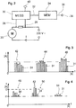
- This connection cable is in FIG. 2 symbolically represented by two contacts, between which the mains voltage 220 V is specified. All this belongs to the state of the art.
- FIG. 2 shows, flows in the electrical leads to the motor current I. It also flows through a resistor 26, which has a very low value in ohms. It is also called shunt resistance. At him falls from a low voltage, the falling voltage is fed via the two leads 28 of the stage MESS, an ammeter 30. In the ammeter 30, the respective current analog value of the current I is present as a small voltage value. It is digitized in an A / D stage located in the flowmeter 30. There are at the output of the current meter 30 to digital signals 31 of the current values, which are delivered in a certain time sequence t. These signals are stored in a stage MEM, a recording unit 34. At the output 36, an output terminal 38 is provided.
- the output terminal 38 the values stored in the recording unit 34 can be retrieved.
- the output terminal 38 may for example be formed so that it has a slot for a commercial USB stick, which is accessible from the outside, outside the box 24.
- the USB stick itself is the entire memory or part of the memory of the recording unit 34. The other part is then in the box 24. If the USB stick removed, it can be replaced by another, the removed stick can then evaluated elsewhere.
- the recording unit 34 has only an internal memory and by inserting a USB stick at the output terminal 38, a start signal is given, that the stored values in the memory are transferred to the USB stick.
- Digitization can take place in relatively rough stages. It suffices a resolution of the current signals in the range of about 50 mA. Generally, a resolution in a range of 1 mA to 500 mA is sufficient.
- the timing of digitizing the current values is typically between 0.1 and 20 seconds.
- FIGS. 3 and 4 show typical signals 31 of the digitized current values.
- signals from three individual milling operations are shown, from each milling process 6 to 7 signals are obtained. This amounts to about a current value per revolution of the cutter blade.
- a higher resolution will be in the Practice used in the rule, the resolution shown is indeed possible, but it was chosen in particular to keep the presentation vivid.
- a first threshold I1 is drawn. It is above the normal motor current, for example, 20% above the motor current I, which is present in a normal milling under conditions specified by the manufacturer of the cap cutter. It can be seen that a left group 42 of six current values is below the first threshold value I1. In the second group 44 of bars, which has a total of seven current values from another milling operation, some values or signals exceed the first threshold value I1. It can be seen that now there is a higher motor current I than in the case of the left group 42.
- the far right in FIG. 3 can be found even higher current values I are achieved.
- This can be z. B. be because the milling operation is performed with a higher contact pressure.
- the values are now noticeably above the first threshold I1.
- the values shown are stored together with the respectively associated time value in a value table in the memory of the recording unit. It then knows at the selected times at which a milling operation was active, the respective associated value of the motor current I. Thus, an assignment is possible from when the motor current has exceeded a certain value, as z. B. in the middle 44 and right group 46 of FIG. 3 the case is.
- the clock signal preferably also contains a date, it is linked to the time-related signal 31 of the motor current I and stored in said value table. This allows you to prove exactly at what time of the day the overcurrent occurred.
- FIG. 4 shows a method in which only the signals 31 are stored, which are above the first threshold value I1. It is still a second threshold I2, it has a value which is within the range of the maximum value of the permissible motor current.
- the value of the first threshold value I1 can be determined by experiments, selecting a current value which is about 10 to 50% above the value found in normal milling applications.
- the current value for the second threshold I2 is selected larger.
- specifications of the manufacturer of the drive motor 20 can be used, for example, the maximum motor current or the maximum power consumption for the drive motor 20.
- the second threshold value I2 can be, for example, 20% below the maximum permissible current value of the drive motor 20.
- FIG. 4 shows a first group 48 on the left, in which four signals are above the first threshold. In a middle group 50, four signals 31 are also above the first threshold value I1, two signals 52 thereof even exceed the second threshold value I2. This can be used to trigger an alarm device 40 connected to the ammeter 30. It can work visually and / or acoustically, but it can also be used elsewhere. Signals such as the two 52 of the middle group 50 that exceed the second threshold I2 may also be routed to a control of an associated welding robot, so that it is caused to reduce the contact pressure.
Landscapes
- Engineering & Computer Science (AREA)
- Mechanical Engineering (AREA)
- Milling Processes (AREA)
- Numerical Control (AREA)
Claims (9)
- Fraise à capot destinée à fraiser la zone de soudage d'électrodes de soudage par points, qui comprend un moteur d'entraînement électrique (20) et au moins une lame-fraise (22), dans laquelle un ampèremètre (30) est prévu qui est disposé dans une ligne d'alimentation vers le moteur d'entraînement (20) et l'ampèremètre (30) peut détecter le courant de moteur I du moteur d'entraînement (20) pendant le fraisage, caractérisée par le fait qu'une unité d'enregistrement (34) est prévue qui peut stocker la valeur du courant de moteur I à des instants individuels, et ladite unité d'enregistrement (34) est conçue de manière à ce que l'on puisse déterminer au moins une valeur de seuil I1 pour le courant de moteur I, et que a) soit un enregistrement n'a lieu dans l'unité d'enregistrement (34) que lorsqu'un courant supérieur à une première valeur de seuil I1 circule à travers le moteur d'entraînement (20), soit b) le nombre de dépassements de la valeur de seuil est stocké dans l'unité d'enregistrement (34) en association avec un signal horaire.
- Fraise à capot selon la revendication 1, caractérisée par le fait que l'unité d'enregistrement (34) présente une borne de sortie (38).
- Fraise à capot selon la revendication 1 ou 2, caractérisée par le fait qu'un enregistrement n'a lieu dans l'unité d'enregistrement (34) que lorsqu'un courant supérieur à la première valeur de seuil I1 circule à travers le moteur d'entraînement (20), et qu'au moins une deuxième valeur de seuil I2 pour le courant de moteur I est déterminable, et qu'un générateur de signal (40) est prévu qui peut délivrer un signal acoustique, optique et/ou électrique (52) lorsqu'une deuxième valeur de seuil I2 est dépassée, I2 étant supérieure à I1.
- Fraise à capot selon l'une quelconque des revendications précédentes, caractérisée par le fait que dans l'unité d'enregistrement (34) peuvent être enregistrés le début d'une circulation de courant à travers le moteur d'entraînement (20) et la fin en association avec un signal horaire.
- Fraise à capot selon l'une quelconque des revendications précédentes, caractérisée par le fait que l'ampèremètre (30) comprend un convertisseur analogique-numérique et un générateur de rythme.
- Fraise à capot selon l'une quelconque des revendications précédentes, caractérisée par le fait que l'ampèremètre (30) comprend une horloge qui peut délivrer un signal horaire avec la date.
- Fraise à capot selon l'une quelconque des revendications 2 à 6, caractérisée par le fait qu'elle comprend une boîte (24) qui est reliée au moteur d'entraînement (20) et dans laquelle sont logés l'ampèremètre (30) et l'unité d'enregistrement (34) et dans laquelle est disposée la borne de sortie (38).
- Fraise à capot selon l'une quelconque des revendications 2 à 7, caractérisée par le fait que la borne de sortie (38) présente une prise femelle pour une clé USB.
- Fraise à capot selon l'une quelconque des revendications 2 à 8, caractérisée par le fait qu'une mémoire est installée de manière permanente dans l'unité d'enregistrement (34) et/ou est connectée de manière amovible à l'unité d'enregistrement (34) par l'intermédiaire de la borne de sortie (38).
Applications Claiming Priority (1)
| Application Number | Priority Date | Filing Date | Title |
|---|---|---|---|
| DE202015103106.8U DE202015103106U1 (de) | 2015-06-12 | 2015-06-12 | Kappenfräser mit einem elektrischen Antriebsmotor und mindestens einem Fräsmesser |
Publications (2)
| Publication Number | Publication Date |
|---|---|
| EP3103579A1 EP3103579A1 (fr) | 2016-12-14 |
| EP3103579B1 true EP3103579B1 (fr) | 2019-10-23 |
Family
ID=53677274
Family Applications (1)
| Application Number | Title | Priority Date | Filing Date |
|---|---|---|---|
| EP16173795.2A Active EP3103579B1 (fr) | 2015-06-12 | 2016-06-09 | Fraise de rodage comprenant un moteur electrique |
Country Status (2)
| Country | Link |
|---|---|
| EP (1) | EP3103579B1 (fr) |
| DE (1) | DE202015103106U1 (fr) |
Families Citing this family (1)
| Publication number | Priority date | Publication date | Assignee | Title |
|---|---|---|---|---|
| EP3124160B1 (fr) * | 2015-07-27 | 2018-05-09 | SVS Schweißtechnik GmbH | Procede adaptatif destine au fraisage des electrodes de dispositifs de soudage par points |
Family Cites Families (7)
| Publication number | Priority date | Publication date | Assignee | Title |
|---|---|---|---|---|
| US5332342A (en) | 1991-04-26 | 1994-07-26 | Honda Giken Kogyo Kabushiki Kaisha | Electrode tip dresser and cutter for electrode tip dresser |
| DE29724590U1 (de) | 1996-05-21 | 2002-04-18 | Lutz, Peter-Stephan, Svaty Jur | Fräseinrichtung |
| DE19825771A1 (de) | 1998-06-09 | 1999-12-16 | Bayerische Motoren Werke Ag | Vorrichtung zum Fräsen von Elektrodenkappen |
| JP4812975B2 (ja) | 2000-09-07 | 2011-11-09 | 富士重工業株式会社 | 電極チップ整形装置 |
| JP4772219B2 (ja) | 2001-06-27 | 2011-09-14 | 富士重工業株式会社 | チップドレッサ用切粉回収装置 |
| JP2006341271A (ja) * | 2005-06-08 | 2006-12-21 | Honda Motor Co Ltd | スポット溶接ロボットの電極チップ整形監視方法及び同監視装置 |
| JP5484551B1 (ja) * | 2012-11-20 | 2014-05-07 | 株式会社キョクトー | 電極チップの研磨方法 |
-
2015
- 2015-06-12 DE DE202015103106.8U patent/DE202015103106U1/de active Active
-
2016
- 2016-06-09 EP EP16173795.2A patent/EP3103579B1/fr active Active
Non-Patent Citations (1)
| Title |
|---|
| None * |
Also Published As
| Publication number | Publication date |
|---|---|
| EP3103579A1 (fr) | 2016-12-14 |
| DE202015103106U1 (de) | 2015-07-03 |
Similar Documents
| Publication | Publication Date | Title |
|---|---|---|
| DE3126276C2 (fr) | ||
| DE102013221273A1 (de) | Verfahren zum Überwachen und Regeln einer Qualität von Schweißpunkten | |
| DE102009016798A1 (de) | Verfahren und Steuergerät zum Überwachen einer Qualität von Schweißpunkten einer Widerstandsschweißzange | |
| DE112008003926T5 (de) | Elektrische Drahterodiermaschine und elektrisches Drahterodierbearbeitungsverfahren | |
| EP3840916B1 (fr) | Contrôle d'outil dans une machine d'usinage de pièces ouvrées | |
| WO2008138520A1 (fr) | Dispositif et procédé de surveillance de dysfonctionnements | |
| DE3023400A1 (de) | Servosteuerverfahren und -system fuer elektroerosive bearbeitung | |
| EP1253991B1 (fr) | Dispositif et procede de commande de soudage par points | |
| EP3103579B1 (fr) | Fraise de rodage comprenant un moteur electrique | |
| EP3290142A1 (fr) | Procédé et dispositif de détermination de l'usure d'electrodes lors de l'electro-érosion | |
| DE2716344A1 (de) | Funkenentladungs-werkzeugmaschine | |
| DE102012025196A1 (de) | Vorrichtung und Verfahren zur Ermittlung eines Verschleisses einer Schweisszange | |
| DE102014215167A1 (de) | Schraub- und/oder nietsystem und verfahren zum überwachen eines schraub- und/oder nietsystems | |
| DE102017002580A1 (de) | Numerische Steuerung, die eine zu ergreifende Massnahme nach dem Erkennen einer Störung erleichtert | |
| EP4257279A1 (fr) | Dispositif de nettoyage pour nettoyer une électrode de soudage d'un outil de soudage et procédé de nettoyage d'une électrode de soudage | |
| DE10137977C1 (de) | Punktschweiß-Steuervorrichtung | |
| DE102008001774A1 (de) | Verfahren zum Betrieb einer Werkzeugmaschine, insbesondere einer Handwerkzeugmaschine | |
| DE4334863C2 (de) | Blockierschutz für ein Elektrowerkzeug | |
| DE3446629C2 (fr) | ||
| DE102015215190A1 (de) | Verfahren und Vorrichtung zum Durchführen eines Schweißprozesses | |
| DE102021115209B4 (de) | Verfahren und Vorrichtung zur Überwachung und/oder Regelung eines Fließloch- und Gewindeformprozesses | |
| EP3124160B1 (fr) | Procede adaptatif destine au fraisage des electrodes de dispositifs de soudage par points | |
| DE3332697C2 (fr) | ||
| WO2017108352A1 (fr) | Procédé permettant de faire fonctionner un outil électrique | |
| EP1528967B1 (fr) | Dispositif et procede de commande de soudage par points |
Legal Events
| Date | Code | Title | Description |
|---|---|---|---|
| PUAI | Public reference made under article 153(3) epc to a published international application that has entered the european phase |
Free format text: ORIGINAL CODE: 0009012 |
|
| STAA | Information on the status of an ep patent application or granted ep patent |
Free format text: STATUS: THE APPLICATION HAS BEEN PUBLISHED |
|
| AK | Designated contracting states |
Kind code of ref document: A1 Designated state(s): AL AT BE BG CH CY CZ DE DK EE ES FI FR GB GR HR HU IE IS IT LI LT LU LV MC MK MT NL NO PL PT RO RS SE SI SK SM TR |
|
| AX | Request for extension of the european patent |
Extension state: BA ME |
|
| STAA | Information on the status of an ep patent application or granted ep patent |
Free format text: STATUS: REQUEST FOR EXAMINATION WAS MADE |
|
| 17P | Request for examination filed |
Effective date: 20170524 |
|
| RBV | Designated contracting states (corrected) |
Designated state(s): AL AT BE BG CH CY CZ DE DK EE ES FI FR GB GR HR HU IE IS IT LI LT LU LV MC MK MT NL NO PL PT RO RS SE SI SK SM TR |
|
| GRAP | Despatch of communication of intention to grant a patent |
Free format text: ORIGINAL CODE: EPIDOSNIGR1 |
|
| STAA | Information on the status of an ep patent application or granted ep patent |
Free format text: STATUS: GRANT OF PATENT IS INTENDED |
|
| INTG | Intention to grant announced |
Effective date: 20190604 |
|
| GRAS | Grant fee paid |
Free format text: ORIGINAL CODE: EPIDOSNIGR3 |
|
| GRAA | (expected) grant |
Free format text: ORIGINAL CODE: 0009210 |
|
| STAA | Information on the status of an ep patent application or granted ep patent |
Free format text: STATUS: THE PATENT HAS BEEN GRANTED |
|
| AK | Designated contracting states |
Kind code of ref document: B1 Designated state(s): AL AT BE BG CH CY CZ DE DK EE ES FI FR GB GR HR HU IE IS IT LI LT LU LV MC MK MT NL NO PL PT RO RS SE SI SK SM TR |
|
| REG | Reference to a national code |
Ref country code: GB Ref legal event code: FG4D Free format text: NOT ENGLISH |
|
| REG | Reference to a national code |
Ref country code: CH Ref legal event code: EP |
|
| REG | Reference to a national code |
Ref country code: IE Ref legal event code: FG4D Free format text: LANGUAGE OF EP DOCUMENT: GERMAN |
|
| REG | Reference to a national code |
Ref country code: AT Ref legal event code: REF Ref document number: 1193135 Country of ref document: AT Kind code of ref document: T Effective date: 20191115 |
|
| REG | Reference to a national code |
Ref country code: DE Ref legal event code: R096 Ref document number: 502016007191 Country of ref document: DE |
|
| REG | Reference to a national code |
Ref country code: NL Ref legal event code: MP Effective date: 20191023 |
|
| REG | Reference to a national code |
Ref country code: LT Ref legal event code: MG4D |
|
| PG25 | Lapsed in a contracting state [announced via postgrant information from national office to epo] |
Ref country code: SE Free format text: LAPSE BECAUSE OF FAILURE TO SUBMIT A TRANSLATION OF THE DESCRIPTION OR TO PAY THE FEE WITHIN THE PRESCRIBED TIME-LIMIT Effective date: 20191023 Ref country code: LV Free format text: LAPSE BECAUSE OF FAILURE TO SUBMIT A TRANSLATION OF THE DESCRIPTION OR TO PAY THE FEE WITHIN THE PRESCRIBED TIME-LIMIT Effective date: 20191023 Ref country code: PL Free format text: LAPSE BECAUSE OF FAILURE TO SUBMIT A TRANSLATION OF THE DESCRIPTION OR TO PAY THE FEE WITHIN THE PRESCRIBED TIME-LIMIT Effective date: 20191023 Ref country code: GR Free format text: LAPSE BECAUSE OF FAILURE TO SUBMIT A TRANSLATION OF THE DESCRIPTION OR TO PAY THE FEE WITHIN THE PRESCRIBED TIME-LIMIT Effective date: 20200124 Ref country code: LT Free format text: LAPSE BECAUSE OF FAILURE TO SUBMIT A TRANSLATION OF THE DESCRIPTION OR TO PAY THE FEE WITHIN THE PRESCRIBED TIME-LIMIT Effective date: 20191023 Ref country code: NL Free format text: LAPSE BECAUSE OF FAILURE TO SUBMIT A TRANSLATION OF THE DESCRIPTION OR TO PAY THE FEE WITHIN THE PRESCRIBED TIME-LIMIT Effective date: 20191023 Ref country code: PT Free format text: LAPSE BECAUSE OF FAILURE TO SUBMIT A TRANSLATION OF THE DESCRIPTION OR TO PAY THE FEE WITHIN THE PRESCRIBED TIME-LIMIT Effective date: 20200224 Ref country code: NO Free format text: LAPSE BECAUSE OF FAILURE TO SUBMIT A TRANSLATION OF THE DESCRIPTION OR TO PAY THE FEE WITHIN THE PRESCRIBED TIME-LIMIT Effective date: 20200123 Ref country code: FI Free format text: LAPSE BECAUSE OF FAILURE TO SUBMIT A TRANSLATION OF THE DESCRIPTION OR TO PAY THE FEE WITHIN THE PRESCRIBED TIME-LIMIT Effective date: 20191023 Ref country code: BG Free format text: LAPSE BECAUSE OF FAILURE TO SUBMIT A TRANSLATION OF THE DESCRIPTION OR TO PAY THE FEE WITHIN THE PRESCRIBED TIME-LIMIT Effective date: 20200123 |
|
| PG25 | Lapsed in a contracting state [announced via postgrant information from national office to epo] |
Ref country code: IS Free format text: LAPSE BECAUSE OF FAILURE TO SUBMIT A TRANSLATION OF THE DESCRIPTION OR TO PAY THE FEE WITHIN THE PRESCRIBED TIME-LIMIT Effective date: 20200224 Ref country code: HR Free format text: LAPSE BECAUSE OF FAILURE TO SUBMIT A TRANSLATION OF THE DESCRIPTION OR TO PAY THE FEE WITHIN THE PRESCRIBED TIME-LIMIT Effective date: 20191023 Ref country code: RS Free format text: LAPSE BECAUSE OF FAILURE TO SUBMIT A TRANSLATION OF THE DESCRIPTION OR TO PAY THE FEE WITHIN THE PRESCRIBED TIME-LIMIT Effective date: 20191023 |
|
| PG25 | Lapsed in a contracting state [announced via postgrant information from national office to epo] |
Ref country code: AL Free format text: LAPSE BECAUSE OF FAILURE TO SUBMIT A TRANSLATION OF THE DESCRIPTION OR TO PAY THE FEE WITHIN THE PRESCRIBED TIME-LIMIT Effective date: 20191023 |
|
| REG | Reference to a national code |
Ref country code: DE Ref legal event code: R097 Ref document number: 502016007191 Country of ref document: DE |
|
| PG2D | Information on lapse in contracting state deleted |
Ref country code: IS |
|
| PG25 | Lapsed in a contracting state [announced via postgrant information from national office to epo] |
Ref country code: RO Free format text: LAPSE BECAUSE OF FAILURE TO SUBMIT A TRANSLATION OF THE DESCRIPTION OR TO PAY THE FEE WITHIN THE PRESCRIBED TIME-LIMIT Effective date: 20191023 Ref country code: CZ Free format text: LAPSE BECAUSE OF FAILURE TO SUBMIT A TRANSLATION OF THE DESCRIPTION OR TO PAY THE FEE WITHIN THE PRESCRIBED TIME-LIMIT Effective date: 20191023 Ref country code: DK Free format text: LAPSE BECAUSE OF FAILURE TO SUBMIT A TRANSLATION OF THE DESCRIPTION OR TO PAY THE FEE WITHIN THE PRESCRIBED TIME-LIMIT Effective date: 20191023 Ref country code: ES Free format text: LAPSE BECAUSE OF FAILURE TO SUBMIT A TRANSLATION OF THE DESCRIPTION OR TO PAY THE FEE WITHIN THE PRESCRIBED TIME-LIMIT Effective date: 20191023 Ref country code: EE Free format text: LAPSE BECAUSE OF FAILURE TO SUBMIT A TRANSLATION OF THE DESCRIPTION OR TO PAY THE FEE WITHIN THE PRESCRIBED TIME-LIMIT Effective date: 20191023 Ref country code: IS Free format text: LAPSE BECAUSE OF FAILURE TO SUBMIT A TRANSLATION OF THE DESCRIPTION OR TO PAY THE FEE WITHIN THE PRESCRIBED TIME-LIMIT Effective date: 20200223 |
|
| PLBE | No opposition filed within time limit |
Free format text: ORIGINAL CODE: 0009261 |
|
| STAA | Information on the status of an ep patent application or granted ep patent |
Free format text: STATUS: NO OPPOSITION FILED WITHIN TIME LIMIT |
|
| PG25 | Lapsed in a contracting state [announced via postgrant information from national office to epo] |
Ref country code: IT Free format text: LAPSE BECAUSE OF FAILURE TO SUBMIT A TRANSLATION OF THE DESCRIPTION OR TO PAY THE FEE WITHIN THE PRESCRIBED TIME-LIMIT Effective date: 20191023 Ref country code: SK Free format text: LAPSE BECAUSE OF FAILURE TO SUBMIT A TRANSLATION OF THE DESCRIPTION OR TO PAY THE FEE WITHIN THE PRESCRIBED TIME-LIMIT Effective date: 20191023 Ref country code: SM Free format text: LAPSE BECAUSE OF FAILURE TO SUBMIT A TRANSLATION OF THE DESCRIPTION OR TO PAY THE FEE WITHIN THE PRESCRIBED TIME-LIMIT Effective date: 20191023 |
|
| 26N | No opposition filed |
Effective date: 20200724 |
|
| PG25 | Lapsed in a contracting state [announced via postgrant information from national office to epo] |
Ref country code: SI Free format text: LAPSE BECAUSE OF FAILURE TO SUBMIT A TRANSLATION OF THE DESCRIPTION OR TO PAY THE FEE WITHIN THE PRESCRIBED TIME-LIMIT Effective date: 20191023 |
|
| REG | Reference to a national code |
Ref country code: DE Ref legal event code: R119 Ref document number: 502016007191 Country of ref document: DE |
|
| PG25 | Lapsed in a contracting state [announced via postgrant information from national office to epo] |
Ref country code: MC Free format text: LAPSE BECAUSE OF FAILURE TO SUBMIT A TRANSLATION OF THE DESCRIPTION OR TO PAY THE FEE WITHIN THE PRESCRIBED TIME-LIMIT Effective date: 20191023 |
|
| REG | Reference to a national code |
Ref country code: CH Ref legal event code: PL |
|
| GBPC | Gb: european patent ceased through non-payment of renewal fee |
Effective date: 20200609 |
|
| PG25 | Lapsed in a contracting state [announced via postgrant information from national office to epo] |
Ref country code: LU Free format text: LAPSE BECAUSE OF NON-PAYMENT OF DUE FEES Effective date: 20200609 |
|
| REG | Reference to a national code |
Ref country code: BE Ref legal event code: MM Effective date: 20200630 |
|
| PG25 | Lapsed in a contracting state [announced via postgrant information from national office to epo] |
Ref country code: CH Free format text: LAPSE BECAUSE OF NON-PAYMENT OF DUE FEES Effective date: 20200630 Ref country code: LI Free format text: LAPSE BECAUSE OF NON-PAYMENT OF DUE FEES Effective date: 20200630 Ref country code: FR Free format text: LAPSE BECAUSE OF NON-PAYMENT OF DUE FEES Effective date: 20200630 Ref country code: IE Free format text: LAPSE BECAUSE OF NON-PAYMENT OF DUE FEES Effective date: 20200609 Ref country code: GB Free format text: LAPSE BECAUSE OF NON-PAYMENT OF DUE FEES Effective date: 20200609 |
|
| PG25 | Lapsed in a contracting state [announced via postgrant information from national office to epo] |
Ref country code: BE Free format text: LAPSE BECAUSE OF NON-PAYMENT OF DUE FEES Effective date: 20200630 Ref country code: DE Free format text: LAPSE BECAUSE OF NON-PAYMENT OF DUE FEES Effective date: 20210101 |
|
| PG25 | Lapsed in a contracting state [announced via postgrant information from national office to epo] |
Ref country code: TR Free format text: LAPSE BECAUSE OF FAILURE TO SUBMIT A TRANSLATION OF THE DESCRIPTION OR TO PAY THE FEE WITHIN THE PRESCRIBED TIME-LIMIT Effective date: 20191023 Ref country code: MT Free format text: LAPSE BECAUSE OF FAILURE TO SUBMIT A TRANSLATION OF THE DESCRIPTION OR TO PAY THE FEE WITHIN THE PRESCRIBED TIME-LIMIT Effective date: 20191023 Ref country code: CY Free format text: LAPSE BECAUSE OF FAILURE TO SUBMIT A TRANSLATION OF THE DESCRIPTION OR TO PAY THE FEE WITHIN THE PRESCRIBED TIME-LIMIT Effective date: 20191023 |
|
| PG25 | Lapsed in a contracting state [announced via postgrant information from national office to epo] |
Ref country code: MK Free format text: LAPSE BECAUSE OF FAILURE TO SUBMIT A TRANSLATION OF THE DESCRIPTION OR TO PAY THE FEE WITHIN THE PRESCRIBED TIME-LIMIT Effective date: 20191023 |
|
| REG | Reference to a national code |
Ref country code: AT Ref legal event code: MM01 Ref document number: 1193135 Country of ref document: AT Kind code of ref document: T Effective date: 20210609 |
|
| PG25 | Lapsed in a contracting state [announced via postgrant information from national office to epo] |
Ref country code: AT Free format text: LAPSE BECAUSE OF NON-PAYMENT OF DUE FEES Effective date: 20210609 |