EP3102368B1 - Outil pour un robot servant à appliquer un fluide visqueux, robot pour appliquer un fluide visqueux, et procédé pour appliquer un fluide visqueux au moyen d'un tel robot - Google Patents
Outil pour un robot servant à appliquer un fluide visqueux, robot pour appliquer un fluide visqueux, et procédé pour appliquer un fluide visqueux au moyen d'un tel robot Download PDFInfo
- Publication number
- EP3102368B1 EP3102368B1 EP15714157.3A EP15714157A EP3102368B1 EP 3102368 B1 EP3102368 B1 EP 3102368B1 EP 15714157 A EP15714157 A EP 15714157A EP 3102368 B1 EP3102368 B1 EP 3102368B1
- Authority
- EP
- European Patent Office
- Prior art keywords
- tool
- tool according
- robot
- supply line
- viscous medium
- Prior art date
- Legal status (The legal status is an assumption and is not a legal conclusion. Google has not performed a legal analysis and makes no representation as to the accuracy of the status listed.)
- Active
Links
- 238000000034 method Methods 0.000 title claims description 21
- 230000006641 stabilisation Effects 0.000 claims description 18
- 238000011105 stabilization Methods 0.000 claims description 18
- 238000003860 storage Methods 0.000 claims description 13
- 230000001050 lubricating effect Effects 0.000 claims description 11
- 239000000463 material Substances 0.000 claims description 6
- 238000010438 heat treatment Methods 0.000 claims description 5
- 230000000087 stabilizing effect Effects 0.000 claims description 3
- 238000005461 lubrication Methods 0.000 description 19
- 206010041953 Staring Diseases 0.000 description 9
- 239000000314 lubricant Substances 0.000 description 9
- 230000006378 damage Effects 0.000 description 8
- 239000004519 grease Substances 0.000 description 5
- 241000282414 Homo sapiens Species 0.000 description 4
- 238000012544 monitoring process Methods 0.000 description 4
- 230000001681 protective effect Effects 0.000 description 4
- 230000006835 compression Effects 0.000 description 2
- 238000007906 compression Methods 0.000 description 2
- 238000010276 construction Methods 0.000 description 2
- 238000006073 displacement reaction Methods 0.000 description 2
- 229920001971 elastomer Polymers 0.000 description 2
- 239000000806 elastomer Substances 0.000 description 2
- 238000004519 manufacturing process Methods 0.000 description 2
- 241000282412 Homo Species 0.000 description 1
- 230000002411 adverse Effects 0.000 description 1
- 238000010924 continuous production Methods 0.000 description 1
- 238000005553 drilling Methods 0.000 description 1
- 239000007788 liquid Substances 0.000 description 1
- 238000003825 pressing Methods 0.000 description 1
- 230000008961 swelling Effects 0.000 description 1
Images


Classifications
-
- B—PERFORMING OPERATIONS; TRANSPORTING
- B25—HAND TOOLS; PORTABLE POWER-DRIVEN TOOLS; MANIPULATORS
- B25J—MANIPULATORS; CHAMBERS PROVIDED WITH MANIPULATION DEVICES
- B25J17/00—Joints
- B25J17/02—Wrist joints
- B25J17/0208—Compliance devices
- B25J17/0233—Compliance devices with radial compliance, i.e. perpendicular to the longitudinal wrist axis
-
- B—PERFORMING OPERATIONS; TRANSPORTING
- B25—HAND TOOLS; PORTABLE POWER-DRIVEN TOOLS; MANIPULATORS
- B25J—MANIPULATORS; CHAMBERS PROVIDED WITH MANIPULATION DEVICES
- B25J11/00—Manipulators not otherwise provided for
- B25J11/0075—Manipulators for painting or coating
-
- B—PERFORMING OPERATIONS; TRANSPORTING
- B25—HAND TOOLS; PORTABLE POWER-DRIVEN TOOLS; MANIPULATORS
- B25J—MANIPULATORS; CHAMBERS PROVIDED WITH MANIPULATION DEVICES
- B25J15/00—Gripping heads and other end effectors
- B25J15/0019—End effectors other than grippers
-
- B—PERFORMING OPERATIONS; TRANSPORTING
- B25—HAND TOOLS; PORTABLE POWER-DRIVEN TOOLS; MANIPULATORS
- B25J—MANIPULATORS; CHAMBERS PROVIDED WITH MANIPULATION DEVICES
- B25J19/00—Accessories fitted to manipulators, e.g. for monitoring, for viewing; Safety devices combined with or specially adapted for use in connection with manipulators
- B25J19/06—Safety devices
- B25J19/063—Safety devices working only upon contact with an outside object
Definitions
- the invention is based on a tool for a robot for applying a viscous medium, which can be used, for example, as a greasing system for greasing a wide variety of components in a wide variety of areas, according to the preamble of claim 1, a robot equipped with such a tool for application a viscous medium, and a method for applying a viscous medium by means of such a robot.
- the pamphlets JP 59092056 A and US 4468695 A disclose a tool for applying a viscous medium according to the preamble of claim 1.
- the object of the invention is therefore to make the scope of automation as wide as possible, taking into account the necessary safety aspect.
- the tool according to the invention for a robot for applying a viscous medium which can be used, for example, as a greasing system for greasing a wide variety of components in a wide variety of areas, according to claim 1, the robot according to the invention for applying a viscous medium according to claim 12, and the method according to the invention for applying a viscous medium by means of a robot, according to claim 13, have the advantage that in the event of a collision of the tool with an object or a person, at least the movable part of the tool performs an evasive movement, so that a high degree of risk is reduced automation is made possible.
- the end of the line can be a nozzle, a dispensing needle or a lubricating tip.
- the end of the line can be closable. This ensures that the medium cannot escape in an uncontrolled manner between the work steps.
- the storage can be resilient and / or flexible. This will prevent damage. Due to the resilience in a given position before a collision, which is achieved for example by spring force and / or elasticity can be, a process disturbed by a collision can be quickly resumed because the displaced tool or the displaced part of the tool is brought back into the position given before a collision. A tool and / or tool part that is deformed and / or displaced by the application of a force thus returns to its original shape and / or position in the absence of the force. With regard to the deformability of the tool or part of the tool (for example at least part of the supply line), it is preferably an elastic deformability.
- corresponding materials in particular an elastomer, can be used, so that, for example, at least part of the supply line consists of an elastomer, so that it is resilient.
- the extensibility of the supply line or the bearing if this is the supply line, for example when the fat is pressed.
- the storage can be a spherical storage.
- a spherical bearing has the advantage that planes of rotation can be inclined in addition to the course in one plane.
- At least one bearing can be blocked by a stabilizing device, which is preferably displaceable. This has the advantage that the supply line is rigid and cannot evade.
- the stabilization device can be arranged at least partially around at least part of the feed line and / or the stabilization device can be at least partially integrated into at least a part of the feed line and / or the stabilization device can be at least a part of the feed line.
- the stabilization device can in particular be arranged at least in regions around a flexible or stretchable part of the supply line, at least around to inhibit or prevent stretching or deformation of the supply line in some areas, especially in the event that the supply line is subjected to pressure.
- the stabilization device can be a sleeve or the stabilization device can be formed by the supply line, which consists at least partially of an intelligent material.
- An intelligent material means a material that becomes rigid when a voltage is applied, for example.
- the sleeve can be arranged displaceably around the supply line.
- the tool can have a heating device.
- the medium can be heated by the heating device, so that this can influence the flowability.
- the tool can have a sensor system.
- the sensor system is preferably a camera or a camera system.
- the advantage of a camera or a camera system is that deviations in the line end position are recognized so that readjustment is possible.
- the robot for dispensing a viscous medium which has a tool which is arranged on the robot by means of a fastening device, a supply line for the viscous medium and a line end which is arranged on the tool and which is arranged at the end of the supply line, the tool at least has a bearing, can have a sensor system.
- the robot can have a sensor system for determining the position of the line end.
- the robot can be a collaborative robot. This enables a collaborative operation of the robot according to the invention with humans.
- the standards EN-ISO 10218-1, EN-ISO 10218-2 and the technical specifications are in Germany of the trade association TS 15066 considerable, whereby these are observed according to the invention.
- a technical solution according to the invention makes collaborative operation possible without a protective fence.
- the aim of the invention is to provide a tool for dispensing, for example, highly viscous (e.g. thick grease) or low viscosity (e.g. thin oil) media, in which the risk potential emanating from the tool, which is particularly given when the tool is moving is reduced by the fact that the tool has at least one bearing, in particular a spherical bearing, by means of which the tool is arranged on the robot, whereby during the time in which the potential hazard is present (e.g. while the tool is moving from a point to be processed another point to be processed), the tool and / or at least a part of the tool is movable.
- highly viscous e.g. thick grease
- low viscosity e.g. thin oil
- the tool and / or a part of the tool give way to a body, in particular a human body part. This prevents damage to the tool and / or part of the tool and / or the body.
- the bearing in particular the spherical bearing, is at least partially stiffened, whereby the one provided for the tool Process can be carried out.
- the tool is a tool according to any one of claims 1 to 11.
- the tool having a fastening device (e.g. connection unit) for attaching the tool to the robot and a feed line for the viscous medium with a line end and the tool having at least one Has storage through which at least a part of the tool is movable, the storage at the latest at the beginning of the application of the viscous medium is blocked by means of a stabilization device, the stabilization device can prevent the feed line from kinking and / or the feed line from expanding during the discharge of the viscous medium.
- a fastening device e.g. connection unit
- the storage can be blocked by means of a stabilization device, so that the storage is blocked by the stabilization device at the latest at the beginning of a work process (e.g. application of a viscous medium).
- the storage can be released by the stabilization device.
- Fig. 1 shows a cross section through a tool according to the invention for robots for greasing in the non-greasing mode.
- the tool according to the invention has a sleeve 1 which is movably arranged on a flexible supply line which serves as a bearing, in particular a spherical bearing.
- a nozzle 3 which has a centering cone 4 on its side facing away from the supply line end and is used to dispense a viscous medium 5 (eg lubricant).
- the sleeve 1 has a recess 6 into which the centering cone 4 of the nozzle 3 can be inserted to connect the nozzle 3 and the sleeve 1.
- Fig. 2 shows a cross section through a tool according to the invention for robots for greasing in greasing mode.
- the sleeve 1 shifted in the direction of the nozzle 3 until the centering cone 4 engages in the corresponding recess 6 arranged on the sleeve 1, as a result of which the flexible supply line 2 is stabilized.
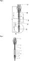
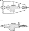
- Fig. 3 shows a cross-section through a further embodiment of a tool according to the invention for robots for greasing in non-greasing mode with a rigid outer casing (sleeve 1) pulled back and a flexible supply line 2 for the lubricant to protect against injuries and a connection unit 7 for the robot.
- a rigid pipe 8 is arranged at least partially inside the flexible supply line 2, by means of which the flexible supply line 2 is stabilized, in particular when the sleeve 1 is displaced in the direction of the nozzle 3.
- the tube 8 avoids an expansion of the flexible supply line 2, which is caused by a required pressure, which is necessary, for example, when a highly viscous (thick) medium (eg fat) is dispensed. This ensures an exact application rate of the medium 5 to be applied.
- a highly viscous (thick) medium eg fat
- Fig. 4 shows a cross section through a tool according to the invention for robots for greasing in greasing mode according to FIG Fig. 3 , in with a rigid outer jacket pushed forward over a flexible supply line 2 for the lubricant. In this position the tool is completely rigid due to the sleeve 1 and the tube 8 and the bearing is blocked.
- Fig. 5 shows a side view of the tool according to the invention, according to Fig. 3 .
- Fig. 6 shows a detailed view of a nozzle 3 of the tool according to the invention, shown in cross section, according to section A from FIG Fig. 3 .
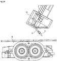
- Fig. 7 shows a cross section through the tool according to the invention on a robot arm and a component 9 to be greased in greasing mode.
- the dimensions given are only examples.
- a metering valve for example a flexible feed line 2 (hose) and a nozzle 3, for example a metering needle.
- the medium 5 is introduced (dragged in) on the surface of the component to be lubricated at reduced pressure.
- a medium 5 with low / low viscosity that is to say a thin liquid medium such as oil
- the method for greasing a component 9 can also be carried out without a rotation.
- Fig. 8 shows a detailed view, shown in cross section, of a nozzle 3 of the tool according to the invention for robots in the greasing mode on a component 9 to be greased, according to section A.
- FIG Fig. 7 shows a detailed view, shown in cross section, of a nozzle 3 of the tool according to the invention for robots in the greasing mode on a component 9 to be greased, according to section A.
- FIG Fig. 7 shows a detailed view, shown in cross section, of a nozzle 3 of the tool according to the invention for robots in the greasing mode on a component 9 to be greased, according to section A.
- FIG Fig. 7 shows a detailed view, shown in cross section, of a nozzle 3 of the tool according to the invention for robots in the greasing mode on a component 9 to be greased, according to section A.
- FIG Fig. 7 shows a detailed view, shown in cross section, of a nozzle 3 of the tool according to the invention for robots in the greasing mode on
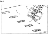
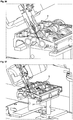
- FIGs. 3 to 25 an embodiment of the tool according to the invention for introducing a highly viscous (viscous) medium 5 into a bore 10 or the like.
- a rigid outer jacket arranged on the tool according to the invention for example a sleeve 1
- Another embodiment of the tool according to the invention for introducing a low-viscosity (low viscosity) medium 5 into a bore 10 or the like There is no rigid outer jacket, for example a sleeve 1, arranged on the tool according to the invention, in different views.
- a nozzle 3 for example a dispensing needle or another outlet device, is connected via a feed line 2, which is pushed away horizontally or vertically bent in the event of a collision with a part of a human body or another obstacle, for example a component 9.
- the connection of the nozzle 3 therefore acts like a spherical bearing. Due to the spherical mounting, the nozzle 3 (lubricating tip) is resilient, resilient and / or flexible. Because the mounting is flexible when the nozzle 3 (lubricating tip) is moved, the nozzle 3 (lubricating tip) can avoid or yield to collisions.
- the bearing is only stiffened by means of the casing 1 when the greasing takes place or shortly before the greasing takes place.
- the medium 5 to be applied eg grease
- the supply line 2 hose
- An example is in Fig. 13 a displacement mechanism 12 for the sleeve 1 is shown.
- an additional advantage of such a spherical mounting is that the tool according to the invention can be adapted in order to be able to compensate for component tolerances or position tolerances.
- a rigid outer jacket here for example a sleeve 1 (protective sleeve)
- a sleeve 1 protective sleeve
- the piece of tubing released when the sleeve 1 is moved is connected to a rigid component arranged inside the flexible supply line 2, e.g. B. a piece of pipe (pipe 8), protected against increased internal pressure and thus against expansion.
- a rigid component arranged inside the flexible supply line 2, e.g. B. a piece of pipe (pipe 8), protected against increased internal pressure and thus against expansion.
- low-viscosity media 5 for example low-viscosity media such as oil
- a rigid outer jacket here for example a sleeve 1
- can be pushed over the hose would prevent compression of the medium 5 and at the same time align and stabilize the nozzle 3 (dispensing needle).
- the flowability can be improved by increasing the temperature. It is therefore also possible to at least partially heat the rigid outer jacket, for example by using a double jacket or an integrated heating coil. However, all other conceivable heating options are also conceivable here. Furthermore, it is also conceivable that the medium 5 is heatable, or at least partially the flexible supply line 2.
- the flexible supply line 2 consists of an intelligent material and becomes rigid, for example when a voltage is applied, so that a displaceable sleeve 1 or a rigid outer jacket to stabilize the flexible supply line 2 against increased internal pressures is no longer necessary is.
- the flexible supply line 2 and the nozzle 3 are located in a shield 11, for example another protective sleeve or the like.
- a shield 11 for example another protective sleeve or the like.
- the spherically mounted nozzle 3 of the tool according to the invention is angled or kinked in the area of the flexible supply line 2 so that it, as e.g. in Fig. 22 is shown in or behind a shield 11. Due to the large surface of this shield 11, the standard values for collaborating robots can be complied with.
- the robot preferably stops in the event of an undesired contact due to its force monitoring and / or sensor system.
- the process monitoring with regard to the position of the nozzle 3 or a needle position comparable to it or the presence of a needle is carried out with the aid of an additional sensor system.
- the exact position of the nozzle 3 or a needle tip is detected in order to be able to correct it with a handling system or robot (TCP offset).
- the process monitoring with regard to the medium 5 takes place via a pressure sensor, which is arranged, for example, on the metering valve.
- the workflow with the tool according to the invention is as follows:
- the workpiece to be greased (component 9) is brought to its processing station in any way, for example via a conveyor, and indexed there, i.e. the workpiece takes an exact position at the processing station on.
- the tool arranged on the robot moves to a first bore 10 (lubrication bore), ie to a first metering position, for greasing.
- This dosing position is preferably programmed in advance in the control system of the robot, so that the robot has to work very precisely with its tool, whereby, as mentioned above, small component or position tolerances can be compensated for by the tool according to the invention.
- the robot arm has an image processing system, for example a camera, which recognizes the position data of the component 9 to be greased and calculates it with the position data of the nozzle 3 so that the exact dosing position can be determined and then controlled.
- a rigid outer jacket for example a sleeve 1
- a centering cone 4 in Fig. 2 or Fig. 4 position shown.
- the position of the nozzle 3 is stabilized and, on the other hand, it is prevented that the flexible supply line 2, for example a hose or a flexible pipe connection, is expanded by the increased internal pressure when the medium 5 is pressed out.
- the rigid outer jacket is removed from the in Fig. 4 position shown in Fig. 3 brought the position shown, so that when changing to a further metering position, the nozzle 3 of the tool according to the invention is spherically mounted and no damage can be caused to a person on contact.
- the next metering position is then approached as described above and the process for greasing a lubrication hole begins again.
- the robot moves to a calibration position, for example a laser curtain, in order to use additional sensors to detect the exact position of the nozzle 3, for example a needle point, on the tool according to the invention for a robot .
- the correction data are determined and offset against the robot position, so that the nozzle 3 is recalibrated. If the position of the nozzle 3 (needle tip) is correct, the workpiece is automatically released or must be removed or released manually after being checked by the employee. After the release, the component 9 leaves the processing position. Now the whole process is repeated.
- a tool according to the invention offers a high degree of autonomy thanks to a large storage container. Few spare and wear parts are necessary, but the dosing head has a very robust and light (eg 800 g) structure.
- the nozzle 3 can be formed, for example, by fine metering needles with an outside diameter of less than 2 mm.
Landscapes
- Engineering & Computer Science (AREA)
- Robotics (AREA)
- Mechanical Engineering (AREA)
- Manipulator (AREA)
Claims (14)
- Outil pour robot d'application d'un milieu visqueux (5),- avec un dispositif de fixation pour fixer l'outil au robot,- avec une conduite d'alimentation (2) pour le fluide visqueux (5)- Avec une extrémité de ligne disposée à l'extrémité de la ligne d'alimentation (2) et- avec au moins un palier flexible à travers lequel l'extrémité de la ligne est montée de manière flexible sur le robot,caractérisé en ce que l'au moins un palier flexible peut être bloqué par un dispositif de stabilisation.
- Outil selon la revendication 1, dans lequel le dispositif de stabilisation est disposé au moins partiellement autour d'au moins une partie de la ligne d'alimentation (2) et / ou le dispositif de stabilisation est au moins partiellement intégré dans au moins une partie de la ligne d'alimentation (2). et / ou le dispositif de stabilisation est au moins partiellement intégré à la ligne d'alimentation (2).
- Outil selon la revendication 1 ou la revendication 2, dans lequel le dispositif de stabilisation est un manchon (1) ou le dispositif de stabilisation est formé par la ligne d'alimentation (2), qui est au moins partiellement constituée d'un matériau intelligent.
- Outil selon la revendication 3, dans lequel le manchon (2) est disposé de manière déplaçable autour de la ligne d'alimentation (2).
- Outil selon l'une des revendications précédentes, dans lequel au moins un palier est disposé sur le dispositif de fixation et / ou la ligne d'alimentation (2).
- Outil selon l'une des revendications précédentes, dans lequel l'extrémité de la ligne est une buse (3), une aiguille de distribution ou une pointe de lubrification.
- Outil selon l'une des revendications précédentes, dans lequel l'extrémité de la ligne peut être fermée.
- Outil selon l'une des revendications précédentes, dans lequel le stockage est élastique et / ou flexible.
- Outil selon l'une des revendications précédentes, dans lequel le stockage est un stockage sphérique.
- Outil selon l'une des revendications précédentes, dans lequel l'outil comporte un dispositif de chauffage.
- Outil selon l'une des revendications précédentes, dans lequel l'outil comporte un système de capteur.
- Robot d'application d'un milieu visqueux, avec un outil selon l'une des revendications précédentes, qui est agencé au moyen de son dispositif de fixation sur le robot.
- Procédé d'application d'un milieu visqueux (5) au moyen d'un robot selon la revendication 12, dans lequel au plus tard au début de l'application du milieu visqueux, un montage flexible de l'outil est bloqué au moyen d'un stabilisateur. dispositif de l'outil.
- Procédé selon la revendication 13, dans lequel le dispositif de stabilisation empêche le vrillage de la ligne d'alimentation (2) et / ou une expansion de la ligne d'alimentation (2) lors de l'application du milieu visqueux (5).
Applications Claiming Priority (2)
| Application Number | Priority Date | Filing Date | Title |
|---|---|---|---|
| DE102014001638 | 2014-02-05 | ||
| PCT/DE2015/000054 WO2015117594A1 (fr) | 2014-02-05 | 2015-02-05 | Outil pour un robot servant à appliquer une milieu visqueux, robot pour appliquer un milieu visqueux, procédé pour appliquer un milieu visqueux au moyen d'un outil pour un robot, procédé pour réduire un potentiel de risque lié à un outil d'un robot |
Publications (2)
| Publication Number | Publication Date |
|---|---|
| EP3102368A1 EP3102368A1 (fr) | 2016-12-14 |
| EP3102368B1 true EP3102368B1 (fr) | 2021-01-27 |
Family
ID=52810911
Family Applications (1)
| Application Number | Title | Priority Date | Filing Date |
|---|---|---|---|
| EP15714157.3A Active EP3102368B1 (fr) | 2014-02-05 | 2015-02-05 | Outil pour un robot servant à appliquer un fluide visqueux, robot pour appliquer un fluide visqueux, et procédé pour appliquer un fluide visqueux au moyen d'un tel robot |
Country Status (3)
| Country | Link |
|---|---|
| EP (1) | EP3102368B1 (fr) |
| DE (1) | DE112015000669A5 (fr) |
| WO (1) | WO2015117594A1 (fr) |
Families Citing this family (1)
| Publication number | Priority date | Publication date | Assignee | Title |
|---|---|---|---|---|
| DE102018205451A1 (de) | 2018-04-11 | 2019-10-17 | Bayerische Motoren Werke Aktiengesellschaft | Verfahren und System zum Bearbeiten oder Behandeln eines Bauteils |
Family Cites Families (4)
| Publication number | Priority date | Publication date | Assignee | Title |
|---|---|---|---|---|
| US4468695A (en) * | 1980-11-20 | 1984-08-28 | Tokico Ltd. | Robot |
| JPS5992056A (ja) * | 1982-11-19 | 1984-05-28 | Tokico Ltd | ノズル装置 |
| US4998606A (en) * | 1990-01-31 | 1991-03-12 | Eoa Systems, Inc. | Programmable breakaway clutch system with collapsible failure mode |
| DE10048749A1 (de) * | 2000-09-29 | 2002-04-11 | Josef Schucker | Anordnung zum Aufbringen von Klebstoff auf ein Werkstück |
-
2015
- 2015-02-05 DE DE112015000669.9T patent/DE112015000669A5/de not_active Withdrawn
- 2015-02-05 EP EP15714157.3A patent/EP3102368B1/fr active Active
- 2015-02-05 WO PCT/DE2015/000054 patent/WO2015117594A1/fr active Application Filing
Non-Patent Citations (1)
| Title |
|---|
| None * |
Also Published As
| Publication number | Publication date |
|---|---|
| EP3102368A1 (fr) | 2016-12-14 |
| WO2015117594A1 (fr) | 2015-08-13 |
| DE112015000669A5 (de) | 2017-04-13 |
Similar Documents
| Publication | Publication Date | Title |
|---|---|---|
| DE102015005606A1 (de) | Kappenfrässystem mit Fräsvorrichtung zum Schneiden von Elektrodenkappen von Punktschweißzange | |
| EP1363063B1 (fr) | Lubricateur | |
| EP2893986A1 (fr) | Lubrification à l'aide de buses d'injection dotées de plusieurs orifices d'entrée d'huile | |
| EP3332640A1 (fr) | Dispositif de détermination des dommages causés par des mauvaises herbes | |
| DE102004039684B4 (de) | Vorrichtung zur Aufbringung einer Leitpaste auf eine gekrümmte Harzglasscheibe | |
| DE102016116797A1 (de) | Vorrichtung und Verfahren zum Reinigen der Oberfläche eines Werkzeugs | |
| EP3622807A1 (fr) | Dispositif de defoliation de plantes | |
| EP3102368B1 (fr) | Outil pour un robot servant à appliquer un fluide visqueux, robot pour appliquer un fluide visqueux, et procédé pour appliquer un fluide visqueux au moyen d'un tel robot | |
| DE4019483C1 (fr) | ||
| EP2929900B1 (fr) | Dispositif d'injection destiné à l'application continue et régulière d'une substance d'injection | |
| DE102020206188A1 (de) | Maschine | |
| DE102015114921A1 (de) | Presspassvorrichtung | |
| WO2018215607A1 (fr) | Dispositif de support | |
| DE102015213438A1 (de) | Stanznietvorrichtung und Fertigungsvorrichtung | |
| EP3386643B1 (fr) | Unité d'application | |
| EP2161113B1 (fr) | Lubrification automatique | |
| DE102020131221A1 (de) | Haltestruktur | |
| DE2129017C3 (de) | Steuereinrichtung an einer Honmaschine zum gleichzeitigen Bearbeiten von mindestens zwei koaxial hintereinanderliegenden Bohrungen | |
| DE102015014625A1 (de) | Verfahren zum zerspanenden Bearbeiten wenigstens eines Strukturelements für einen Kraftwagen | |
| DE102017123913A1 (de) | Vorrichtung zum Auftragen eines viskosen Materials | |
| DE202019102697U1 (de) | Werkzeug zum Umformen eines Hohlkörpers und Werkzeugmaschine mit einem derartigen Werkzeug | |
| DE102014106106A1 (de) | Beschichtungsvorrichtung und Verfahren zum Beschichten einer Werkstückfläche | |
| DE102015105936B4 (de) | Rotor für eine Rundläuferpresse | |
| DE102017220064B4 (de) | Einschraubvorrichtung zum automatisierten Einschrauben und Verfahren | |
| DE102021108201B3 (de) | System und Verfahren zur Abarbeitung einer Montageaufgabe mittels eines Roboters |
Legal Events
| Date | Code | Title | Description |
|---|---|---|---|
| PUAI | Public reference made under article 153(3) epc to a published international application that has entered the european phase |
Free format text: ORIGINAL CODE: 0009012 |
|
| STAA | Information on the status of an ep patent application or granted ep patent |
Free format text: STATUS: REQUEST FOR EXAMINATION WAS MADE |
|
| 17P | Request for examination filed |
Effective date: 20160818 |
|
| AK | Designated contracting states |
Kind code of ref document: A1 Designated state(s): AL AT BE BG CH CY CZ DE DK EE ES FI FR GB GR HR HU IE IS IT LI LT LU LV MC MK MT NL NO PL PT RO RS SE SI SK SM TR |
|
| AX | Request for extension of the european patent |
Extension state: BA ME |
|
| DAX | Request for extension of the european patent (deleted) | ||
| GRAP | Despatch of communication of intention to grant a patent |
Free format text: ORIGINAL CODE: EPIDOSNIGR1 |
|
| STAA | Information on the status of an ep patent application or granted ep patent |
Free format text: STATUS: GRANT OF PATENT IS INTENDED |
|
| INTG | Intention to grant announced |
Effective date: 20200818 |
|
| GRAS | Grant fee paid |
Free format text: ORIGINAL CODE: EPIDOSNIGR3 |
|
| GRAA | (expected) grant |
Free format text: ORIGINAL CODE: 0009210 |
|
| STAA | Information on the status of an ep patent application or granted ep patent |
Free format text: STATUS: THE PATENT HAS BEEN GRANTED |
|
| AK | Designated contracting states |
Kind code of ref document: B1 Designated state(s): AL AT BE BG CH CY CZ DE DK EE ES FI FR GB GR HR HU IE IS IT LI LT LU LV MC MK MT NL NO PL PT RO RS SE SI SK SM TR |
|
| REG | Reference to a national code |
Ref country code: GB Ref legal event code: FG4D Free format text: NOT ENGLISH |
|
| REG | Reference to a national code |
Ref country code: CH Ref legal event code: EP |
|
| REG | Reference to a national code |
Ref country code: AT Ref legal event code: REF Ref document number: 1357927 Country of ref document: AT Kind code of ref document: T Effective date: 20210215 |
|
| REG | Reference to a national code |
Ref country code: IE Ref legal event code: FG4D Free format text: LANGUAGE OF EP DOCUMENT: GERMAN |
|
| REG | Reference to a national code |
Ref country code: DE Ref legal event code: R096 Ref document number: 502015014205 Country of ref document: DE |
|
| REG | Reference to a national code |
Ref country code: NL Ref legal event code: MP Effective date: 20210127 |
|
| REG | Reference to a national code |
Ref country code: LT Ref legal event code: MG9D |
|
| PG25 | Lapsed in a contracting state [announced via postgrant information from national office to epo] |
Ref country code: LT Free format text: LAPSE BECAUSE OF FAILURE TO SUBMIT A TRANSLATION OF THE DESCRIPTION OR TO PAY THE FEE WITHIN THE PRESCRIBED TIME-LIMIT Effective date: 20210127 Ref country code: PT Free format text: LAPSE BECAUSE OF FAILURE TO SUBMIT A TRANSLATION OF THE DESCRIPTION OR TO PAY THE FEE WITHIN THE PRESCRIBED TIME-LIMIT Effective date: 20210527 Ref country code: GR Free format text: LAPSE BECAUSE OF FAILURE TO SUBMIT A TRANSLATION OF THE DESCRIPTION OR TO PAY THE FEE WITHIN THE PRESCRIBED TIME-LIMIT Effective date: 20210428 Ref country code: HR Free format text: LAPSE BECAUSE OF FAILURE TO SUBMIT A TRANSLATION OF THE DESCRIPTION OR TO PAY THE FEE WITHIN THE PRESCRIBED TIME-LIMIT Effective date: 20210127 Ref country code: FI Free format text: LAPSE BECAUSE OF FAILURE TO SUBMIT A TRANSLATION OF THE DESCRIPTION OR TO PAY THE FEE WITHIN THE PRESCRIBED TIME-LIMIT Effective date: 20210127 Ref country code: BG Free format text: LAPSE BECAUSE OF FAILURE TO SUBMIT A TRANSLATION OF THE DESCRIPTION OR TO PAY THE FEE WITHIN THE PRESCRIBED TIME-LIMIT Effective date: 20210427 Ref country code: NO Free format text: LAPSE BECAUSE OF FAILURE TO SUBMIT A TRANSLATION OF THE DESCRIPTION OR TO PAY THE FEE WITHIN THE PRESCRIBED TIME-LIMIT Effective date: 20210427 Ref country code: NL Free format text: LAPSE BECAUSE OF FAILURE TO SUBMIT A TRANSLATION OF THE DESCRIPTION OR TO PAY THE FEE WITHIN THE PRESCRIBED TIME-LIMIT Effective date: 20210127 |
|
| PG25 | Lapsed in a contracting state [announced via postgrant information from national office to epo] |
Ref country code: SE Free format text: LAPSE BECAUSE OF FAILURE TO SUBMIT A TRANSLATION OF THE DESCRIPTION OR TO PAY THE FEE WITHIN THE PRESCRIBED TIME-LIMIT Effective date: 20210127 Ref country code: PL Free format text: LAPSE BECAUSE OF FAILURE TO SUBMIT A TRANSLATION OF THE DESCRIPTION OR TO PAY THE FEE WITHIN THE PRESCRIBED TIME-LIMIT Effective date: 20210127 Ref country code: RS Free format text: LAPSE BECAUSE OF FAILURE TO SUBMIT A TRANSLATION OF THE DESCRIPTION OR TO PAY THE FEE WITHIN THE PRESCRIBED TIME-LIMIT Effective date: 20210127 Ref country code: LV Free format text: LAPSE BECAUSE OF FAILURE TO SUBMIT A TRANSLATION OF THE DESCRIPTION OR TO PAY THE FEE WITHIN THE PRESCRIBED TIME-LIMIT Effective date: 20210127 |
|
| PG25 | Lapsed in a contracting state [announced via postgrant information from national office to epo] |
Ref country code: IS Free format text: LAPSE BECAUSE OF FAILURE TO SUBMIT A TRANSLATION OF THE DESCRIPTION OR TO PAY THE FEE WITHIN THE PRESCRIBED TIME-LIMIT Effective date: 20210527 |
|
| REG | Reference to a national code |
Ref country code: BE Ref legal event code: MM Effective date: 20210228 |
|
| REG | Reference to a national code |
Ref country code: DE Ref legal event code: R097 Ref document number: 502015014205 Country of ref document: DE |
|
| PG25 | Lapsed in a contracting state [announced via postgrant information from national office to epo] |
Ref country code: CZ Free format text: LAPSE BECAUSE OF FAILURE TO SUBMIT A TRANSLATION OF THE DESCRIPTION OR TO PAY THE FEE WITHIN THE PRESCRIBED TIME-LIMIT Effective date: 20210127 Ref country code: EE Free format text: LAPSE BECAUSE OF FAILURE TO SUBMIT A TRANSLATION OF THE DESCRIPTION OR TO PAY THE FEE WITHIN THE PRESCRIBED TIME-LIMIT Effective date: 20210127 Ref country code: LI Free format text: LAPSE BECAUSE OF NON-PAYMENT OF DUE FEES Effective date: 20210228 Ref country code: MC Free format text: LAPSE BECAUSE OF FAILURE TO SUBMIT A TRANSLATION OF THE DESCRIPTION OR TO PAY THE FEE WITHIN THE PRESCRIBED TIME-LIMIT Effective date: 20210127 Ref country code: LU Free format text: LAPSE BECAUSE OF NON-PAYMENT OF DUE FEES Effective date: 20210205 Ref country code: CH Free format text: LAPSE BECAUSE OF NON-PAYMENT OF DUE FEES Effective date: 20210228 Ref country code: SM Free format text: LAPSE BECAUSE OF FAILURE TO SUBMIT A TRANSLATION OF THE DESCRIPTION OR TO PAY THE FEE WITHIN THE PRESCRIBED TIME-LIMIT Effective date: 20210127 |
|
| PG25 | Lapsed in a contracting state [announced via postgrant information from national office to epo] |
Ref country code: DK Free format text: LAPSE BECAUSE OF FAILURE TO SUBMIT A TRANSLATION OF THE DESCRIPTION OR TO PAY THE FEE WITHIN THE PRESCRIBED TIME-LIMIT Effective date: 20210127 Ref country code: ES Free format text: LAPSE BECAUSE OF FAILURE TO SUBMIT A TRANSLATION OF THE DESCRIPTION OR TO PAY THE FEE WITHIN THE PRESCRIBED TIME-LIMIT Effective date: 20210127 Ref country code: SK Free format text: LAPSE BECAUSE OF FAILURE TO SUBMIT A TRANSLATION OF THE DESCRIPTION OR TO PAY THE FEE WITHIN THE PRESCRIBED TIME-LIMIT Effective date: 20210127 Ref country code: RO Free format text: LAPSE BECAUSE OF FAILURE TO SUBMIT A TRANSLATION OF THE DESCRIPTION OR TO PAY THE FEE WITHIN THE PRESCRIBED TIME-LIMIT Effective date: 20210127 |
|
| PLBE | No opposition filed within time limit |
Free format text: ORIGINAL CODE: 0009261 |
|
| STAA | Information on the status of an ep patent application or granted ep patent |
Free format text: STATUS: NO OPPOSITION FILED WITHIN TIME LIMIT |
|
| 26N | No opposition filed |
Effective date: 20211028 |
|
| PG25 | Lapsed in a contracting state [announced via postgrant information from national office to epo] |
Ref country code: IE Free format text: LAPSE BECAUSE OF NON-PAYMENT OF DUE FEES Effective date: 20210205 Ref country code: AL Free format text: LAPSE BECAUSE OF FAILURE TO SUBMIT A TRANSLATION OF THE DESCRIPTION OR TO PAY THE FEE WITHIN THE PRESCRIBED TIME-LIMIT Effective date: 20210127 |
|
| PG25 | Lapsed in a contracting state [announced via postgrant information from national office to epo] |
Ref country code: SI Free format text: LAPSE BECAUSE OF FAILURE TO SUBMIT A TRANSLATION OF THE DESCRIPTION OR TO PAY THE FEE WITHIN THE PRESCRIBED TIME-LIMIT Effective date: 20210127 |
|
| REG | Reference to a national code |
Ref country code: AT Ref legal event code: MM01 Ref document number: 1357927 Country of ref document: AT Kind code of ref document: T Effective date: 20210205 |
|
| PG25 | Lapsed in a contracting state [announced via postgrant information from national office to epo] |
Ref country code: IT Free format text: LAPSE BECAUSE OF FAILURE TO SUBMIT A TRANSLATION OF THE DESCRIPTION OR TO PAY THE FEE WITHIN THE PRESCRIBED TIME-LIMIT Effective date: 20210127 Ref country code: AT Free format text: LAPSE BECAUSE OF NON-PAYMENT OF DUE FEES Effective date: 20210205 |
|
| PG25 | Lapsed in a contracting state [announced via postgrant information from national office to epo] |
Ref country code: IS Free format text: LAPSE BECAUSE OF FAILURE TO SUBMIT A TRANSLATION OF THE DESCRIPTION OR TO PAY THE FEE WITHIN THE PRESCRIBED TIME-LIMIT Effective date: 20210527 |
|
| PG25 | Lapsed in a contracting state [announced via postgrant information from national office to epo] |
Ref country code: BE Free format text: LAPSE BECAUSE OF NON-PAYMENT OF DUE FEES Effective date: 20210228 |
|
| PG25 | Lapsed in a contracting state [announced via postgrant information from national office to epo] |
Ref country code: HU Free format text: LAPSE BECAUSE OF FAILURE TO SUBMIT A TRANSLATION OF THE DESCRIPTION OR TO PAY THE FEE WITHIN THE PRESCRIBED TIME-LIMIT; INVALID AB INITIO Effective date: 20150205 |
|
| PG25 | Lapsed in a contracting state [announced via postgrant information from national office to epo] |
Ref country code: CY Free format text: LAPSE BECAUSE OF FAILURE TO SUBMIT A TRANSLATION OF THE DESCRIPTION OR TO PAY THE FEE WITHIN THE PRESCRIBED TIME-LIMIT Effective date: 20210127 |
|
| P01 | Opt-out of the competence of the unified patent court (upc) registered |
Effective date: 20230530 |
|
| PGFP | Annual fee paid to national office [announced via postgrant information from national office to epo] |
Ref country code: GB Payment date: 20231214 Year of fee payment: 10 |
|
| PGFP | Annual fee paid to national office [announced via postgrant information from national office to epo] |
Ref country code: FR Payment date: 20231212 Year of fee payment: 10 |
|
| PG25 | Lapsed in a contracting state [announced via postgrant information from national office to epo] |
Ref country code: MK Free format text: LAPSE BECAUSE OF FAILURE TO SUBMIT A TRANSLATION OF THE DESCRIPTION OR TO PAY THE FEE WITHIN THE PRESCRIBED TIME-LIMIT Effective date: 20210127 |
|
| PGFP | Annual fee paid to national office [announced via postgrant information from national office to epo] |
Ref country code: DE Payment date: 20231212 Year of fee payment: 10 |