EP3102368B1 - Tool for a robot for applying a viscous medium, robot for applying a viscous medium, and method for applying a viscous medium by means of such a robot - Google Patents
Tool for a robot for applying a viscous medium, robot for applying a viscous medium, and method for applying a viscous medium by means of such a robot Download PDFInfo
- Publication number
- EP3102368B1 EP3102368B1 EP15714157.3A EP15714157A EP3102368B1 EP 3102368 B1 EP3102368 B1 EP 3102368B1 EP 15714157 A EP15714157 A EP 15714157A EP 3102368 B1 EP3102368 B1 EP 3102368B1
- Authority
- EP
- European Patent Office
- Prior art keywords
- tool
- tool according
- robot
- supply line
- viscous medium
- Prior art date
- Legal status (The legal status is an assumption and is not a legal conclusion. Google has not performed a legal analysis and makes no representation as to the accuracy of the status listed.)
- Active
Links
- 238000000034 method Methods 0.000 title claims description 21
- 230000006641 stabilisation Effects 0.000 claims description 18
- 238000011105 stabilization Methods 0.000 claims description 18
- 238000003860 storage Methods 0.000 claims description 13
- 230000001050 lubricating effect Effects 0.000 claims description 11
- 239000000463 material Substances 0.000 claims description 6
- 238000010438 heat treatment Methods 0.000 claims description 5
- 230000000087 stabilizing effect Effects 0.000 claims description 3
- 238000005461 lubrication Methods 0.000 description 19
- 206010041953 Staring Diseases 0.000 description 9
- 239000000314 lubricant Substances 0.000 description 9
- 230000006378 damage Effects 0.000 description 8
- 239000004519 grease Substances 0.000 description 5
- 241000282414 Homo sapiens Species 0.000 description 4
- 238000012544 monitoring process Methods 0.000 description 4
- 230000001681 protective effect Effects 0.000 description 4
- 230000006835 compression Effects 0.000 description 2
- 238000007906 compression Methods 0.000 description 2
- 238000010276 construction Methods 0.000 description 2
- 238000006073 displacement reaction Methods 0.000 description 2
- 229920001971 elastomer Polymers 0.000 description 2
- 239000000806 elastomer Substances 0.000 description 2
- 238000004519 manufacturing process Methods 0.000 description 2
- 241000282412 Homo Species 0.000 description 1
- 230000002411 adverse Effects 0.000 description 1
- 238000010924 continuous production Methods 0.000 description 1
- 238000005553 drilling Methods 0.000 description 1
- 239000007788 liquid Substances 0.000 description 1
- 238000003825 pressing Methods 0.000 description 1
- 230000008961 swelling Effects 0.000 description 1
Images


Classifications
-
- B—PERFORMING OPERATIONS; TRANSPORTING
- B25—HAND TOOLS; PORTABLE POWER-DRIVEN TOOLS; MANIPULATORS
- B25J—MANIPULATORS; CHAMBERS PROVIDED WITH MANIPULATION DEVICES
- B25J17/00—Joints
- B25J17/02—Wrist joints
- B25J17/0208—Compliance devices
- B25J17/0233—Compliance devices with radial compliance, i.e. perpendicular to the longitudinal wrist axis
-
- B—PERFORMING OPERATIONS; TRANSPORTING
- B25—HAND TOOLS; PORTABLE POWER-DRIVEN TOOLS; MANIPULATORS
- B25J—MANIPULATORS; CHAMBERS PROVIDED WITH MANIPULATION DEVICES
- B25J11/00—Manipulators not otherwise provided for
- B25J11/0075—Manipulators for painting or coating
-
- B—PERFORMING OPERATIONS; TRANSPORTING
- B25—HAND TOOLS; PORTABLE POWER-DRIVEN TOOLS; MANIPULATORS
- B25J—MANIPULATORS; CHAMBERS PROVIDED WITH MANIPULATION DEVICES
- B25J15/00—Gripping heads and other end effectors
- B25J15/0019—End effectors other than grippers
-
- B—PERFORMING OPERATIONS; TRANSPORTING
- B25—HAND TOOLS; PORTABLE POWER-DRIVEN TOOLS; MANIPULATORS
- B25J—MANIPULATORS; CHAMBERS PROVIDED WITH MANIPULATION DEVICES
- B25J19/00—Accessories fitted to manipulators, e.g. for monitoring, for viewing; Safety devices combined with or specially adapted for use in connection with manipulators
- B25J19/06—Safety devices
- B25J19/063—Safety devices working only upon contact with an outside object
Definitions
- the invention is based on a tool for a robot for applying a viscous medium, which can be used, for example, as a greasing system for greasing a wide variety of components in a wide variety of areas, according to the preamble of claim 1, a robot equipped with such a tool for application a viscous medium, and a method for applying a viscous medium by means of such a robot.
- the pamphlets JP 59092056 A and US 4468695 A disclose a tool for applying a viscous medium according to the preamble of claim 1.
- the object of the invention is therefore to make the scope of automation as wide as possible, taking into account the necessary safety aspect.
- the tool according to the invention for a robot for applying a viscous medium which can be used, for example, as a greasing system for greasing a wide variety of components in a wide variety of areas, according to claim 1, the robot according to the invention for applying a viscous medium according to claim 12, and the method according to the invention for applying a viscous medium by means of a robot, according to claim 13, have the advantage that in the event of a collision of the tool with an object or a person, at least the movable part of the tool performs an evasive movement, so that a high degree of risk is reduced automation is made possible.
- the end of the line can be a nozzle, a dispensing needle or a lubricating tip.
- the end of the line can be closable. This ensures that the medium cannot escape in an uncontrolled manner between the work steps.
- the storage can be resilient and / or flexible. This will prevent damage. Due to the resilience in a given position before a collision, which is achieved for example by spring force and / or elasticity can be, a process disturbed by a collision can be quickly resumed because the displaced tool or the displaced part of the tool is brought back into the position given before a collision. A tool and / or tool part that is deformed and / or displaced by the application of a force thus returns to its original shape and / or position in the absence of the force. With regard to the deformability of the tool or part of the tool (for example at least part of the supply line), it is preferably an elastic deformability.
- corresponding materials in particular an elastomer, can be used, so that, for example, at least part of the supply line consists of an elastomer, so that it is resilient.
- the extensibility of the supply line or the bearing if this is the supply line, for example when the fat is pressed.
- the storage can be a spherical storage.
- a spherical bearing has the advantage that planes of rotation can be inclined in addition to the course in one plane.
- At least one bearing can be blocked by a stabilizing device, which is preferably displaceable. This has the advantage that the supply line is rigid and cannot evade.
- the stabilization device can be arranged at least partially around at least part of the feed line and / or the stabilization device can be at least partially integrated into at least a part of the feed line and / or the stabilization device can be at least a part of the feed line.
- the stabilization device can in particular be arranged at least in regions around a flexible or stretchable part of the supply line, at least around to inhibit or prevent stretching or deformation of the supply line in some areas, especially in the event that the supply line is subjected to pressure.
- the stabilization device can be a sleeve or the stabilization device can be formed by the supply line, which consists at least partially of an intelligent material.
- An intelligent material means a material that becomes rigid when a voltage is applied, for example.
- the sleeve can be arranged displaceably around the supply line.
- the tool can have a heating device.
- the medium can be heated by the heating device, so that this can influence the flowability.
- the tool can have a sensor system.
- the sensor system is preferably a camera or a camera system.
- the advantage of a camera or a camera system is that deviations in the line end position are recognized so that readjustment is possible.
- the robot for dispensing a viscous medium which has a tool which is arranged on the robot by means of a fastening device, a supply line for the viscous medium and a line end which is arranged on the tool and which is arranged at the end of the supply line, the tool at least has a bearing, can have a sensor system.
- the robot can have a sensor system for determining the position of the line end.
- the robot can be a collaborative robot. This enables a collaborative operation of the robot according to the invention with humans.
- the standards EN-ISO 10218-1, EN-ISO 10218-2 and the technical specifications are in Germany of the trade association TS 15066 considerable, whereby these are observed according to the invention.
- a technical solution according to the invention makes collaborative operation possible without a protective fence.
- the aim of the invention is to provide a tool for dispensing, for example, highly viscous (e.g. thick grease) or low viscosity (e.g. thin oil) media, in which the risk potential emanating from the tool, which is particularly given when the tool is moving is reduced by the fact that the tool has at least one bearing, in particular a spherical bearing, by means of which the tool is arranged on the robot, whereby during the time in which the potential hazard is present (e.g. while the tool is moving from a point to be processed another point to be processed), the tool and / or at least a part of the tool is movable.
- highly viscous e.g. thick grease
- low viscosity e.g. thin oil
- the tool and / or a part of the tool give way to a body, in particular a human body part. This prevents damage to the tool and / or part of the tool and / or the body.
- the bearing in particular the spherical bearing, is at least partially stiffened, whereby the one provided for the tool Process can be carried out.
- the tool is a tool according to any one of claims 1 to 11.
- the tool having a fastening device (e.g. connection unit) for attaching the tool to the robot and a feed line for the viscous medium with a line end and the tool having at least one Has storage through which at least a part of the tool is movable, the storage at the latest at the beginning of the application of the viscous medium is blocked by means of a stabilization device, the stabilization device can prevent the feed line from kinking and / or the feed line from expanding during the discharge of the viscous medium.
- a fastening device e.g. connection unit
- the storage can be blocked by means of a stabilization device, so that the storage is blocked by the stabilization device at the latest at the beginning of a work process (e.g. application of a viscous medium).
- the storage can be released by the stabilization device.
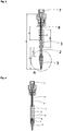
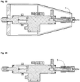
- Fig. 1 shows a cross section through a tool according to the invention for robots for greasing in the non-greasing mode.
- the tool according to the invention has a sleeve 1 which is movably arranged on a flexible supply line which serves as a bearing, in particular a spherical bearing.
- a nozzle 3 which has a centering cone 4 on its side facing away from the supply line end and is used to dispense a viscous medium 5 (eg lubricant).
- the sleeve 1 has a recess 6 into which the centering cone 4 of the nozzle 3 can be inserted to connect the nozzle 3 and the sleeve 1.
- Fig. 2 shows a cross section through a tool according to the invention for robots for greasing in greasing mode.
- the sleeve 1 shifted in the direction of the nozzle 3 until the centering cone 4 engages in the corresponding recess 6 arranged on the sleeve 1, as a result of which the flexible supply line 2 is stabilized.
- Fig. 3 shows a cross-section through a further embodiment of a tool according to the invention for robots for greasing in non-greasing mode with a rigid outer casing (sleeve 1) pulled back and a flexible supply line 2 for the lubricant to protect against injuries and a connection unit 7 for the robot.
- a rigid pipe 8 is arranged at least partially inside the flexible supply line 2, by means of which the flexible supply line 2 is stabilized, in particular when the sleeve 1 is displaced in the direction of the nozzle 3.
- the tube 8 avoids an expansion of the flexible supply line 2, which is caused by a required pressure, which is necessary, for example, when a highly viscous (thick) medium (eg fat) is dispensed. This ensures an exact application rate of the medium 5 to be applied.
- a highly viscous (thick) medium eg fat
- Fig. 4 shows a cross section through a tool according to the invention for robots for greasing in greasing mode according to FIG Fig. 3 , in with a rigid outer jacket pushed forward over a flexible supply line 2 for the lubricant. In this position the tool is completely rigid due to the sleeve 1 and the tube 8 and the bearing is blocked.
- Fig. 5 shows a side view of the tool according to the invention, according to Fig. 3 .
- Fig. 6 shows a detailed view of a nozzle 3 of the tool according to the invention, shown in cross section, according to section A from FIG Fig. 3 .
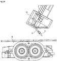
- Fig. 7 shows a cross section through the tool according to the invention on a robot arm and a component 9 to be greased in greasing mode.
- the dimensions given are only examples.
- a metering valve for example a flexible feed line 2 (hose) and a nozzle 3, for example a metering needle.
- the medium 5 is introduced (dragged in) on the surface of the component to be lubricated at reduced pressure.
- a medium 5 with low / low viscosity that is to say a thin liquid medium such as oil
- the method for greasing a component 9 can also be carried out without a rotation.
- Fig. 8 shows a detailed view, shown in cross section, of a nozzle 3 of the tool according to the invention for robots in the greasing mode on a component 9 to be greased, according to section A.
- FIG Fig. 7 shows a detailed view, shown in cross section, of a nozzle 3 of the tool according to the invention for robots in the greasing mode on a component 9 to be greased, according to section A.
- FIG Fig. 7 shows a detailed view, shown in cross section, of a nozzle 3 of the tool according to the invention for robots in the greasing mode on a component 9 to be greased, according to section A.
- FIG Fig. 7 shows a detailed view, shown in cross section, of a nozzle 3 of the tool according to the invention for robots in the greasing mode on a component 9 to be greased, according to section A.
- FIG Fig. 7 shows a detailed view, shown in cross section, of a nozzle 3 of the tool according to the invention for robots in the greasing mode on
- FIGs. 3 to 25 an embodiment of the tool according to the invention for introducing a highly viscous (viscous) medium 5 into a bore 10 or the like.
- a rigid outer jacket arranged on the tool according to the invention for example a sleeve 1
- Another embodiment of the tool according to the invention for introducing a low-viscosity (low viscosity) medium 5 into a bore 10 or the like There is no rigid outer jacket, for example a sleeve 1, arranged on the tool according to the invention, in different views.
- a nozzle 3 for example a dispensing needle or another outlet device, is connected via a feed line 2, which is pushed away horizontally or vertically bent in the event of a collision with a part of a human body or another obstacle, for example a component 9.
- the connection of the nozzle 3 therefore acts like a spherical bearing. Due to the spherical mounting, the nozzle 3 (lubricating tip) is resilient, resilient and / or flexible. Because the mounting is flexible when the nozzle 3 (lubricating tip) is moved, the nozzle 3 (lubricating tip) can avoid or yield to collisions.
- the bearing is only stiffened by means of the casing 1 when the greasing takes place or shortly before the greasing takes place.
- the medium 5 to be applied eg grease
- the supply line 2 hose
- An example is in Fig. 13 a displacement mechanism 12 for the sleeve 1 is shown.
- an additional advantage of such a spherical mounting is that the tool according to the invention can be adapted in order to be able to compensate for component tolerances or position tolerances.
- a rigid outer jacket here for example a sleeve 1 (protective sleeve)
- a sleeve 1 protective sleeve
- the piece of tubing released when the sleeve 1 is moved is connected to a rigid component arranged inside the flexible supply line 2, e.g. B. a piece of pipe (pipe 8), protected against increased internal pressure and thus against expansion.
- a rigid component arranged inside the flexible supply line 2, e.g. B. a piece of pipe (pipe 8), protected against increased internal pressure and thus against expansion.
- low-viscosity media 5 for example low-viscosity media such as oil
- a rigid outer jacket here for example a sleeve 1
- can be pushed over the hose would prevent compression of the medium 5 and at the same time align and stabilize the nozzle 3 (dispensing needle).
- the flowability can be improved by increasing the temperature. It is therefore also possible to at least partially heat the rigid outer jacket, for example by using a double jacket or an integrated heating coil. However, all other conceivable heating options are also conceivable here. Furthermore, it is also conceivable that the medium 5 is heatable, or at least partially the flexible supply line 2.
- the flexible supply line 2 consists of an intelligent material and becomes rigid, for example when a voltage is applied, so that a displaceable sleeve 1 or a rigid outer jacket to stabilize the flexible supply line 2 against increased internal pressures is no longer necessary is.
- the flexible supply line 2 and the nozzle 3 are located in a shield 11, for example another protective sleeve or the like.
- a shield 11 for example another protective sleeve or the like.
- the spherically mounted nozzle 3 of the tool according to the invention is angled or kinked in the area of the flexible supply line 2 so that it, as e.g. in Fig. 22 is shown in or behind a shield 11. Due to the large surface of this shield 11, the standard values for collaborating robots can be complied with.
- the robot preferably stops in the event of an undesired contact due to its force monitoring and / or sensor system.
- the process monitoring with regard to the position of the nozzle 3 or a needle position comparable to it or the presence of a needle is carried out with the aid of an additional sensor system.
- the exact position of the nozzle 3 or a needle tip is detected in order to be able to correct it with a handling system or robot (TCP offset).
- the process monitoring with regard to the medium 5 takes place via a pressure sensor, which is arranged, for example, on the metering valve.
- the workflow with the tool according to the invention is as follows:
- the workpiece to be greased (component 9) is brought to its processing station in any way, for example via a conveyor, and indexed there, i.e. the workpiece takes an exact position at the processing station on.
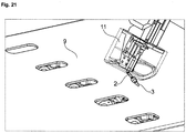
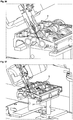
- the tool arranged on the robot moves to a first bore 10 (lubrication bore), ie to a first metering position, for greasing.
- This dosing position is preferably programmed in advance in the control system of the robot, so that the robot has to work very precisely with its tool, whereby, as mentioned above, small component or position tolerances can be compensated for by the tool according to the invention.
- the robot arm has an image processing system, for example a camera, which recognizes the position data of the component 9 to be greased and calculates it with the position data of the nozzle 3 so that the exact dosing position can be determined and then controlled.
- a rigid outer jacket for example a sleeve 1
- a centering cone 4 in Fig. 2 or Fig. 4 position shown.
- the position of the nozzle 3 is stabilized and, on the other hand, it is prevented that the flexible supply line 2, for example a hose or a flexible pipe connection, is expanded by the increased internal pressure when the medium 5 is pressed out.
- the rigid outer jacket is removed from the in Fig. 4 position shown in Fig. 3 brought the position shown, so that when changing to a further metering position, the nozzle 3 of the tool according to the invention is spherically mounted and no damage can be caused to a person on contact.
- the next metering position is then approached as described above and the process for greasing a lubrication hole begins again.
- the robot moves to a calibration position, for example a laser curtain, in order to use additional sensors to detect the exact position of the nozzle 3, for example a needle point, on the tool according to the invention for a robot .
- the correction data are determined and offset against the robot position, so that the nozzle 3 is recalibrated. If the position of the nozzle 3 (needle tip) is correct, the workpiece is automatically released or must be removed or released manually after being checked by the employee. After the release, the component 9 leaves the processing position. Now the whole process is repeated.
- a tool according to the invention offers a high degree of autonomy thanks to a large storage container. Few spare and wear parts are necessary, but the dosing head has a very robust and light (eg 800 g) structure.
- the nozzle 3 can be formed, for example, by fine metering needles with an outside diameter of less than 2 mm.
Description
Die Erfindung geht aus von einem Werkzeug für einen Roboter zur Ausbringung eines viskosen Mediums, welches beispielsweise als Befettsystem für das Befetten von unterschiedlichsten Bauteilen in den unterschiedlichsten Bereichen eingesetzt werden kann, nach der Gattung des Anspruchs 1, einem mit einem solchen Werkzeug ausgestatteten Roboter zur Ausbringung eines viskosen Mediums, und einem Verfahren zur Ausbringung eines viskosen Mediums mittels eines solchen Roboters.The invention is based on a tool for a robot for applying a viscous medium, which can be used, for example, as a greasing system for greasing a wide variety of components in a wide variety of areas, according to the preamble of
Werkzeuge für einen Roboter gehören seit langer Zeit zum Stand der Technik. Bei dem Einsatz eines Roboters können Produktionsschritte automatisiert werden. Trotz dieser Automatisierung, die in der Regel eine Bewegung des Roboters und/oder eine Bewegung des zu bearbeitenden Teils beinhaltet, muss aber sichergestellt werden, dass die automatisierten Arbeitsschritte zuverlässig durchgeführt und den qualitativen Ansprüchen bzgl. des Arbeitsergebnisses entsprechen. Zudem sind die Anforderungen an die Arbeitssicherheit recht hoch, so dass das Gefährdungspotential, das von einem automatisierten Prozess ausgeht, möglichst gering gehalten werden soll. All dies kann sich nachteilig auf den Umfang der Automatisierung auswirken.Tools for a robot have been state of the art for a long time. When using a robot, production steps can be automated. Despite this automation, which usually includes a movement of the robot and / or a movement of the part to be processed, it must be ensured that the automated work steps are carried out reliably and meet the qualitative requirements with regard to the work result. In addition, the requirements for occupational safety are quite high, so that the potential risk that an automated process poses should be kept as low as possible. All of this can adversely affect the level of automation.
Die Druckschriften
Das erfindungsgemäße Werkzeug für einen Roboter zur Ausbringung eines viskosen Mediums, welches beispielsweise als Befettsystem für das Befetten von unterschiedlichsten Bauteilen in den unterschiedlichsten Bereichen eingesetzt werden kann, gemäß Anspruch 1, der erfindungsgemäße Roboter zur Ausbringung eines viskosen Mediums gemäß Anspruch 12, und das erfindungsgemäße Verfahren zur Ausbringung eines viskosen Mediums mittels eines Roboters, gemäß Anspruch 13, haben demgegenüber den Vorteil, dass bei einer Kollision des Werkzeuges mit einem Gegenstand oder einem Menschen mindestens der bewegliche Teil des Werkzeuges eine Ausweichbewegung vollführt, so dass durch eine Reduzierung des Gefährdungspotential ein hoher Grad an Automatisierung ermöglicht wird.The tool according to the invention for a robot for applying a viscous medium, which can be used, for example, as a greasing system for greasing a wide variety of components in a wide variety of areas, according to
Das Leitungsende kann eine Düse, eine Dosiernadel oder eine Schmierspitze sein. Das Leitungsende kann verschließbar sein. Hierdurch wird sichergestellt, dass das Medium zwischen den Arbeitsschritten nicht unkontrolliert austreten kann.The end of the line can be a nozzle, a dispensing needle or a lubricating tip. The end of the line can be closable. This ensures that the medium cannot escape in an uncontrolled manner between the work steps.
Die Lagerung kann rückstellfähig und/oder flexibel sein. Dadurch werden Schäden vermieden. Durch die Rückstellfähigkeit in eine vor einer Kollision gegebene Position, die beispielsweise durch Federkraft und/oder Elastizität bewerkstelligt werden kann, kann ein durch eine Kollision gestörtes Verfahren zügig wieder aufgenommen werden, da das verlagerte Werkzeug oder der verlagerte Teil des Werkzeuges wieder in die vor einer Kollision gegebene Position gebracht wird. Eine durch Anlegen einer Kraft verformtes und/oder verlagertes Werkzeug und/oder Werkzeugteil, kehrt somit bei Abwesenheit der Kraft wieder in die ursprüngliche Form und/oder Lage zurück. Bzgl. der Verformbarkeit des Werkzeuges oder eines Teils des Werkzeuges (z.B. zumindest ein Teil der Zuleitung) handelt es sich bevorzugt um eine elastische Verformbarkeit. Um die Verformbarkeit und/oder Rückstellfähigkeit zu bewerkstelligen, können dementsprechende Werkstoffe, insbesondere ein Elastomer eingesetzt werden, so dass z.B. zumindest ein Teil der Zuleitung aus einem Elastomer besteht, so dass es dadurch rückstellfähig ausgebildet ist. In diesem Zusammenhang steht auch die Dehnbarkeit der Zuleitung bzw. der Lagerung, wenn dies die Zuleitung ist, wenn z.B. das Fett gepresst wird.The storage can be resilient and / or flexible. This will prevent damage. Due to the resilience in a given position before a collision, which is achieved for example by spring force and / or elasticity can be, a process disturbed by a collision can be quickly resumed because the displaced tool or the displaced part of the tool is brought back into the position given before a collision. A tool and / or tool part that is deformed and / or displaced by the application of a force thus returns to its original shape and / or position in the absence of the force. With regard to the deformability of the tool or part of the tool (for example at least part of the supply line), it is preferably an elastic deformability. In order to achieve the deformability and / or resilience, corresponding materials, in particular an elastomer, can be used, so that, for example, at least part of the supply line consists of an elastomer, so that it is resilient. In this context, there is also the extensibility of the supply line or the bearing, if this is the supply line, for example when the fat is pressed.
Die Lagerung kann eine sphärische Lagerung sein. Eine sphärische Lagerung hat den Vorteil, dass Drehebenen neben dem Verlauf in einer Ebene auch schräg stehen können.The storage can be a spherical storage. A spherical bearing has the advantage that planes of rotation can be inclined in addition to the course in one plane.
Mindestens eine Lagerung ist durch eine Stabilisierungsvorrichtung, die bevorzugt verschiebbar ist, blockierbar. Dies hat den Vorteil, dass die Zuleitung starr ist und nicht ausweichen kann.At least one bearing can be blocked by a stabilizing device, which is preferably displaceable. This has the advantage that the supply line is rigid and cannot evade.
Die Stabilisierungsvorrichtung kann zumindest teilweise um zumindest einen Teil der Zuleitung angeordnet sein und/oder die Stabilisierungsvorrichtung kann zumindest teilweise in zumindest einen Teil der Zuleitung integriert sein und/oder die Stabilisierungsvorrichtung kann zumindest einen Teil der Zuleitung sein.The stabilization device can be arranged at least partially around at least part of the feed line and / or the stabilization device can be at least partially integrated into at least a part of the feed line and / or the stabilization device can be at least a part of the feed line.
Die Stabilisierungsvorrichtung kann insbesondere zumindest bereichsweise um einen flexibel bzw. dehnbar ausgebildeten Teil der Zuleitung angeordnet sein, um zumindest bereichsweise eine Dehnung bzw. Verformung der Zuleitung zu hemmen bzw. zu verhindern, insbesondere für den Fall, dass die Zuleitung mit einem Druck beaufschlagt wird.The stabilization device can in particular be arranged at least in regions around a flexible or stretchable part of the supply line, at least around to inhibit or prevent stretching or deformation of the supply line in some areas, especially in the event that the supply line is subjected to pressure.
Die Stabilisierungsvorrichtung kann eine Hülse sein oder die Stabilisierungsvorrichtung kann durch die Zuleitung gebildet werden, die zumindest teilweise aus einem intelligenten Werkstoff besteht. Mit einem intelligenten Werkstoff ist ein Werkstoff gemeint, der beispielsweise bei einem Anlegen einer Spannung starr wird.The stabilization device can be a sleeve or the stabilization device can be formed by the supply line, which consists at least partially of an intelligent material. An intelligent material means a material that becomes rigid when a voltage is applied, for example.
Die Hülse kann verschieblich um die Zuleitung angeordnet sein.The sleeve can be arranged displaceably around the supply line.
Das Werkzeug kann eine Heizvorrichtung aufweisen. Durch die Heizvorrichtung kann das Medium erwärmt werden, so dass dadurch ein Einfluss auf die Fließfähigkeit ausgeübt werden kann.The tool can have a heating device. The medium can be heated by the heating device, so that this can influence the flowability.
Das Werkzeug kann eine Sensorik aufweisen. Bevorzugt ist die Sensorik eine Kamera oder ein Kamerasystem. Der Vorteil einer Kamera oder eines Kamerasystems besteht darin, dass Abweichungen bei der Leitungsendeposition erkannt werden, so dass eine Nachjustierung möglich wird.The tool can have a sensor system. The sensor system is preferably a camera or a camera system. The advantage of a camera or a camera system is that deviations in the line end position are recognized so that readjustment is possible.
Der Roboters zur Ausbringung eines viskosen Mediums, der ein Werkzeug, das mittels einer Befestigungsvorrichtung an dem Roboter angeordnet ist, eine Zuleitung für das viskose Medium und ein am Werkzeug angeordnetes Leitungsende, das am Ende der Zuleitung angeordnet ist, aufweist, wobei dass das Werkzeug mindestens eine Lagerung aufweist, kann eine Sensorik aufweisen.The robot for dispensing a viscous medium, which has a tool which is arranged on the robot by means of a fastening device, a supply line for the viscous medium and a line end which is arranged on the tool and which is arranged at the end of the supply line, the tool at least has a bearing, can have a sensor system.
Der Roboter kann eine Sensorik zur Positionsbestimmung des Leitungsendes aufweisen.The robot can have a sensor system for determining the position of the line end.
Der Roboter kann ein kollaborierender Roboter sein. Dadurch wird ein kollaborierender Betrieb des erfindungsgemäßen Roboters mit dem Menschen ermöglicht. Für einen solchen kollaborierenden Betrieb zwischen Mensch und Maschine sind in Deutschland die Normen EN-ISO 10218-1, EN-ISO 10218-2 sowie die technische Spezifikationen der Berufsgenossenschaft TS 15066 beachtlich, wobei diese erfindungsgemäß eingehalten werden.The robot can be a collaborative robot. This enables a collaborative operation of the robot according to the invention with humans. For such a collaborative operation between man and machine, the standards EN-ISO 10218-1, EN-ISO 10218-2 and the technical specifications are in Germany of the trade association TS 15066 considerable, whereby these are observed according to the invention.
Eine erfindungsgemäße technische Lösung macht einen kollaborierenden Betrieb ohne Schutzzaun möglich. Ziel der Erfindung ist es ein Werkzeug zum Ausbringen von z.B. hochviskosen (bspw. dickflüssiges Fett) oder niedrigviskosen (bspw. dünnflüssiges Öl) Medien, zur Verfügung zu stellen, bei dem das von dem Werkzeug ausgehende Gefahrenpotenzial, das insbesondere bei Bewegung des Werkzeuges gegeben ist, dadurch reduziert wird, dass das Werkzeug mindestens eine Lagerung, insbesondere eine sphärische Lagerung, aufweist mittels dieser das Werkzeug an dem Roboter angeordnet ist, wodurch während der Zeit, in der das Gefahrenpotenzial vorhanden ist (z.B. während das Werkzeug von einer zu bearbeitenden Stelle zu einer anderen zu bearbeitenden Stelle verbracht wird), das Werkzeug und/oder zumindest ein Teil des Werkzeuges beweglich ist. Aufgrund dieser Beweglichkeit weichen das Werkzeug und/oder ein Teil des Werkzeuges einem Körper, insbesondere einem menschlichen Körperteil, aus. Hierdurch wird eine Beschädigung des Werkzeuges und/oder eines Teils des Werkzeuges und/oder des Körpers vermieden. Spätestens wenn das Gefahrenpotenzial und/oder die Gefahr einer Beschädigung nicht gegeben oder zumindest als unerheblich angesehen wird, insbesondere, wenn sich das Werkzeug in der Arbeitsposition befindet, wird die Lagerung, insbesondere die sphärische Lagerung, zumindest teilweise versteift, wodurch der für das Werkzeug vorgesehene Prozess durchgeführt werden kann.A technical solution according to the invention makes collaborative operation possible without a protective fence. The aim of the invention is to provide a tool for dispensing, for example, highly viscous (e.g. thick grease) or low viscosity (e.g. thin oil) media, in which the risk potential emanating from the tool, which is particularly given when the tool is moving is reduced by the fact that the tool has at least one bearing, in particular a spherical bearing, by means of which the tool is arranged on the robot, whereby during the time in which the potential hazard is present (e.g. while the tool is moving from a point to be processed another point to be processed), the tool and / or at least a part of the tool is movable. Because of this mobility, the tool and / or a part of the tool give way to a body, in particular a human body part. This prevents damage to the tool and / or part of the tool and / or the body. At the latest when the hazard potential and / or the risk of damage is not given or is at least viewed as insignificant, in particular when the tool is in the working position, the bearing, in particular the spherical bearing, is at least partially stiffened, whereby the one provided for the tool Process can be carried out.
Das Werkzeug ist ein Werkzeug nach einem der Ansprüche 1 bis 11.The tool is a tool according to any one of
Bei dem erfindungsgemäßen Verfahren zur Ausbringung eines viskosen Mediums mittels eines mit einem solchen Werkzeug ausgestatteten Roboters, wobei das Werkzeug eine Befestigungsvorrichtung (z.B. Anschlusseinheit) zur Anbringung des Werkzeuges an dem Roboter und eine Zuleitung für das viskose Medium mit einem Leitungsende aufweist und das Werkzeug mindestens eine Lagerung aufweist, durch die mindestens ein Teil des Werkzeuges bewegbar ist, wobei spätestens zu Beginn der zur Ausbringung des viskosen Mediums die Lagerung mittels einer Stabilisierungsvorrichtung blockiert wird, kann die Stabilisierungsvorrichtung ein Abknicken der Zuleitung und/oder eine Ausdehnung der Zuleitung bei der Ausbringung des viskosen Mediums verhindern.In the method according to the invention for applying a viscous medium by means of a robot equipped with such a tool, the tool having a fastening device (e.g. connection unit) for attaching the tool to the robot and a feed line for the viscous medium with a line end and the tool having at least one Has storage through which at least a part of the tool is movable, the storage at the latest at the beginning of the application of the viscous medium is blocked by means of a stabilization device, the stabilization device can prevent the feed line from kinking and / or the feed line from expanding during the discharge of the viscous medium.
Nach der Ausbringung des viskosen Mediums kann die Lagerung durch die Stabilisierungsvorrichtung freigegeben werden.After the viscous medium has been applied, storage can be released by the stabilization device.
Bei einem nicht zur Erfindung gehörenden Verfahren zur Reduzierung eines von einem Werkzeug eines Roboters ausgehenden Gefahrenpotenzials, bei dem das Werkzeug mindestens eine Lagerung aufweist, durch die mindestens ein Teil des Werkzeuges bewegbar ist, so dass bei einer Kollision des Werkzeuges mit einem Gegenstand oder einem Menschen mindestens der bewegliche Teil des Werkzeuges eine Ausweichbewegung vollführt, kann die Lagerung mittels einer Stabilisierungsvorrichtung blockiert werden, so dass die Lagerung spätestens zu Beginn eines Arbeitsprozesses (z.B. einer Ausbringung eines viskosen Mediums) mittels der Stabilisierungsvorrichtung blockiert ist.In a method not belonging to the invention for reducing a hazard potential emanating from a tool of a robot, in which the tool has at least one bearing through which at least a part of the tool can be moved, so that if the tool collides with an object or a person At least the movable part of the tool performs an evasive movement, the storage can be blocked by means of a stabilization device, so that the storage is blocked by the stabilization device at the latest at the beginning of a work process (e.g. application of a viscous medium).
Spätestens nach einem Arbeitsprozess (z.B. der Ausbringung des viskosen Mediums) kann die Lagerung durch die Stabilisierungsvorrichtung freigegeben werden.At the latest after a work process (e.g. the application of the viscous medium), the storage can be released by the stabilization device.
Weitere Vorteile und vorteilhafte Ausgestaltungen der Erfindung sind der nachfolgenden Beschreibung, der Zeichnung und den Ansprüchen entnehmbar.Further advantages and advantageous embodiments of the invention can be found in the following description, the drawing and the claims.
Bevorzugte Ausführungsbeispiele des erfindungsgemäßen Gegenstands sind in der Zeichnung dargestellt und werden im Folgenden näher erläutert. Es zeigen
- Fig. 1
- einen Querschnitt durch ein erfindungsgemäßes Werkzeug für Roboter zum Befetten im Nicht-Befett-Modus mit einer flexiblen Zuleitung für das Schmiermittel zum Schutz vor Verletzungen,
- Fig. 2
- einen Querschnitt durch ein erfindungsgemäßes Werkzeug für Roboter zum Befetten im Befett-Modus mit einem nach vorne geschobenen starren Außenmantel über einer flexiblen Zuleitung für das Schmiermittel,
- Fig. 3
- einen Querschnitt durch ein weiteres Ausführungsbeispiel eines erfindungsgemäßen Werkzeuges für Roboter zum Befetten im Nicht-Befett-Modus mit nach hinten gezogenen starren Außenmantel und einer flexiblen Zuleitung für das Schmiermittel zum Schutz vor Verletzungen sowie der Anschlusseinheit für den Roboter,
- Fig. 4
- einen Querschnitt durch ein erfindungsgemäßes Werkzeug für Roboter zum Befetten im Befett-Modus, gemäß
Fig. 3 , in mit einem nach vorne geschobenen starren Außenmantel über einer flexiblen Zuleitung für das Schmiermittel, - Fig. 5
- eine Seitenansicht des erfindungsgemäßen Werkzeuges, gemäß
Fig. 3 , - Fig. 6
- eine im Querschnitt gezeigte Detailansicht einer Düse des erfindungsgemäßen Werkzeuges, gemäß Ausschnitt A aus
Fig. 3 , - Fig. 7
- einen Querschnitt durch das erfindungsgemäße Werkzeug an einem Roboterarm und ein zu befettendes Bauteil im Befett-Modus,
- Fig. 8
- eine im Querschnitt gezeigte Detailansicht (mit beispielhafter Bemaßung) einer Düse des erfindungsgemäßen Werkzeuges für Roboter im Befett-Modus an einem zu befettenden Bauteil, gemäß Ausschnitt A aus
Fig. 7 , - Fig. 9
- eine dreidimensionale Ansicht des erfindungsgemäßen Werkzeuges an einem Roboterarm im Befett-Modus und einen Querschnitt eines zu befettenden Bauteils,
- Fig. 10
- eine dreidimensionale Ansicht des erfindungsgemäßen Werkzeuges an einem Roboterarm im Befett-Modus,
- Fig. 11
- eine weitere dreidimensionale Ansicht des erfindungsgemäßen Werkzeuges an einem Roboterarm im Befett-Modus,
- Fig. 12
- eine weitere dreidimensionale Ansicht des erfindungsgemäßen Werkzeuges an einem Roboterarm im Befett-Modus,
- Fig. 13
- eine weitere dreidimensionale Ansicht des erfindungsgemäßen Werkzeuges an einem Roboterarm im Befett-Modus,
- Fig. 14
- eine weitere dreidimensionale Ansicht des erfindungsgemäßen Werkzeuges an einem Roboterarm im Befett-Modus,
- Fig. 15
- eine weitere dreidimensionale Ansicht im Querschnitt durch eine Düse des erfindungsgemäßen Werkzeuges für Roboter im Befett-Modus an einer zu befettenden Schmierbohrung des Bauteils,
- Fig. 16
- eine weitere dreidimensionale perspektivische Ansicht im Querschnitt durch eine Düse des erfindungsgemäßen Werkzeuges für Roboter im Befett-Modus an einer zu befettenden Schmierbohrung des Bauteils,
- Fig. 17
- eine weitere dreidimensionale Ansicht im Querschnitt durch eine Düse des erfindungsgemäßen Werkzeuges für Roboter im Nicht-Befett-Modus bei der Annäherung an eine zu befettende Schmierbohrung des Bauteils,
- Fig. 18
- eine weitere dreidimensionale Ansicht einer Düse des erfindungsgemäßen Werkzeuges für Roboter im Nicht-Befett-Modus bei der Annäherung an eine zu befettende Schmierbohrung des Bauteils,
- Fig. 19
- eine weitere dreidimensionale Ansicht einer Düse des erfindungsgemäßen Werkzeuges für Roboter im Nicht-Befett-Modus bei der Annäherung an eine zu befettende Schmierbohrung des Bauteils,
- Fig. 20
- eine weitere dreidimensionale Ansicht des erfindungsgemäßen Werkzeuges an einem Roboterarm im Nicht-Befett-Modus mit abgewinkelter Düse,
- Fig. 21
- eine weitere dreidimensionale Ansicht des erfindungsgemäßen Werkzeuges an einem Roboterarm im Nicht-Befett-Modus mit abgewinkelter Düse bei Annäherung an eine zu befettende Schmierbohrung des Bauteils,
- Fig. 22
- eine weitere dreidimensionale Seitenansicht des erfindungsgemäßen Werkzeuges im Nicht-Befett-Modus mit abgeknickter Düse, welche sich in bzw. hinter einer Abschirmung befindet,
- Fig. 23
- eine weitere dreidimensionale Seitenansicht des erfindungsgemäßen Werkzeuges im Nicht-Befett-Modus mit abgeknickter Düse, welche sich in bzw. hinter einer Abschirmung befindet,
- Fig. 24
- eine weitere dreidimensionale Ansicht im Querschnitt durch die Düse des erfindungsgemäßen Werkzeuges im Nicht-Befett-Modus mit abgeknickter Düse, welche sich in bzw. hinter einer Abschirmung oberhalb des Bauteils mit den zu befettenden Schmierbohrungen befindet,
- Fig. 25
- eine weitere dreidimensionale Seitenansicht einer Düse des erfindungsgemäßen Werkzeuges im Nicht-Befett-Modus mit abgewinkelter Düse, die sich in bzw. hinter einer Abschirmung oberhalb des Bauteils mit den zu befettenden Schmierbohrungen befindet, um ein Gefahrenpotenzial zu reduzieren,
- Fig. 26
- eine dreidimensionale Ansicht des erfindungsgemäßen Werkzeuges an einem Roboterarm zum Beölen einer Schmierbohrung des Bauteils ohne starren Außenmantel an der flexiblen Zuleitung im Querschnitt, wobei sich das erfindungsgemäße Werkzeug in Beölposition befindet,
- Fig. 27
- eine weitere dreidimensionale Ansicht des erfindungsgemäßen Werkzeuges an einem Roboterarm zum Beölen einer Schmierbohrung des Bauteils ohne starren Außenmantel an der flexiblen Zuleitung im Querschnitt, wobei sich das erfindungsgemäße Werkzeug in Beölposition befindet,
- Fig. 28
- eine weitere dreidimensionale Ansicht des erfindungsgemäßen Werkzeuges an einem Roboterarm zum Beölen einer Schmierbohrung des Bauteils ohne starren Außenmantel an der flexiblen Zuleitung, wobei sich das erfindungsgemäße Werkzeug in Beölposition befindet,
- Fig. 29
- eine weitere dreidimensionale Ansicht des erfindungsgemäßen Werkzeuges an einem Roboterarm zum Beölen einer Schmierbohrung des Bauteils ohne starren Außenmantel an der flexiblen Zuleitung im Querschnitt, wobei sich das erfindungsgemäße Werkzeug in Beölposition befindet,
- Fig. 30
- eine weitere dreidimensionale Ansicht des erfindungsgemäßen Werkzeuges an einem Roboterarm zum Beölen einer Schmierbohrung des Bauteils ohne starren Außenmantel an der flexiblen Zuleitung im Querschnitt, wobei sich das erfindungsgemäße Werkzeug in Beölposition befindet,
- Fig. 31
- eine weitere dreidimensionale Ansicht des erfindungsgemäßen Werkzeuges an einem Roboterarm zum Beölen einer Schmierbohrung des Bauteils ohne starren Außenmantel an der flexiblen Zuleitung im Querschnitt, wobei sich das erfindungsgemäße Werkzeug in Beölposition befindet,
- Fig. 32
- eine Aufsicht auf eine Schnittzeichnung des erfindungsgemäßen Werkzeuges,
- Fig. 33
- eine Detailansicht des erfindungsgemäßen Werkzeuges, gemäß
Fig. 32 , - Fig. 34
- eine Seitenansicht auf eine Schnittzeichnung des erfindungsgemäßen Werkzeuges,
- Fig. 35
- eine Seitenansicht auf eine Schnittzeichnung des erfindungsgemäßen Werkzeuges und
- Fig. 36
- eine Detailansicht des erfindungsgemäßen Werkzeuges, gemäß
Fig. 35 .
- Fig. 1
- a cross section through a tool according to the invention for robots for greasing in non-greasing mode with a flexible feed line for the lubricant to protect against injuries,
- Fig. 2
- a cross section through a tool according to the invention for robots for greasing in greasing mode with a rigid outer jacket pushed forward over a flexible feed line for the lubricant,
- Fig. 3
- a cross-section through a further embodiment of a tool according to the invention for robots for greasing in non-greasing mode with a rigid outer jacket pulled back and a flexible supply line for the lubricant to protect against injuries and the connection unit for the robot,
- Fig. 4
- a cross section through a tool according to the invention for robots for greasing in greasing mode, according to
Fig. 3 , in with a rigid outer jacket pushed forward over a flexible supply line for the lubricant, - Fig. 5
- a side view of the tool according to the invention, according to
Fig. 3 , - Fig. 6
- a detailed view shown in cross section of a nozzle of the tool according to the invention, according to section A from
Fig. 3 , - Fig. 7
- a cross section through the tool according to the invention on a robot arm and a component to be greased in greasing mode,
- Fig. 8
- a detailed view shown in cross section (with exemplary dimensions) of a nozzle of the tool according to the invention for robots in greasing mode on a component to be greased, according to section A.
Fig. 7 , - Fig. 9
- a three-dimensional view of the tool according to the invention on a robot arm in greasing mode and a cross section of a component to be greased,
- Fig. 10
- a three-dimensional view of the tool according to the invention on a robot arm in greasing mode,
- Fig. 11
- a further three-dimensional view of the tool according to the invention on a robot arm in lubricating mode,
- Fig. 12
- a further three-dimensional view of the tool according to the invention on a robot arm in lubricating mode,
- Fig. 13
- a further three-dimensional view of the tool according to the invention on a robot arm in lubricating mode,
- Fig. 14
- a further three-dimensional view of the tool according to the invention on a robot arm in lubricating mode,
- Fig. 15
- a further three-dimensional view in cross section through a nozzle of the tool according to the invention for robots in greasing mode on a lubrication hole to be greased in the component,
- Fig. 16
- a further three-dimensional perspective view in cross section through a nozzle of the tool according to the invention for robots in lubrication mode on a lubrication hole to be lubricated in the component,
- Fig. 17
- Another three-dimensional view in cross section through a nozzle of the tool according to the invention for robots in non-greasing mode when approaching a lubrication hole of the component to be greased,
- Fig. 18
- a further three-dimensional view of a nozzle of the tool according to the invention for robots in non-greasing mode when approaching a lubrication hole to be greased in the component,
- Fig. 19
- a further three-dimensional view of a nozzle of the tool according to the invention for robots in non-greasing mode when approaching a lubrication hole to be greased in the component,
- Fig. 20
- another three-dimensional view of the tool according to the invention on a robot arm in non-greasing mode with an angled nozzle,
- Fig. 21
- Another three-dimensional view of the tool according to the invention on a robot arm in non-greasing mode with an angled nozzle when approaching a lubrication hole to be greased in the component,
- Fig. 22
- Another three-dimensional side view of the tool according to the invention in the non-greasing mode with a kinked nozzle, which is located in or behind a shield,
- Fig. 23
- Another three-dimensional side view of the tool according to the invention in the non-greasing mode with a kinked nozzle, which is located in or behind a shield,
- Fig. 24
- Another three-dimensional view in cross section through the nozzle of the tool according to the invention in the non-greasing mode with a kinked nozzle, which is located in or behind a shield above the component with the lubrication holes to be greased,
- Fig. 25
- a further three-dimensional side view of a nozzle of the tool according to the invention in non-greasing mode with an angled nozzle, which is located in or behind a shield above the component with the lubrication holes to be greased are located in order to reduce a potential hazard,
- Fig. 26
- a three-dimensional view of the tool according to the invention on a robot arm for oiling a lubrication hole of the component without a rigid outer jacket on the flexible supply line in cross section, the tool according to the invention being in the oiling position,
- Fig. 27
- a further three-dimensional view of the tool according to the invention on a robot arm for oiling a lubrication hole of the component without a rigid outer jacket on the flexible supply line in cross section, the tool according to the invention being in the oiling position,
- Fig. 28
- Another three-dimensional view of the tool according to the invention on a robot arm for oiling a lubrication hole of the component without a rigid outer jacket on the flexible supply line, the tool according to the invention being in the oiling position,
- Fig. 29
- a further three-dimensional view of the tool according to the invention on a robot arm for oiling a lubrication hole of the component without a rigid outer jacket on the flexible supply line in cross section, the tool according to the invention being in the oiling position,
- Fig. 30
- a further three-dimensional view of the tool according to the invention on a robot arm for oiling a lubrication hole of the component without a rigid outer jacket on the flexible supply line in cross section, the tool according to the invention being in the oiling position,
- Fig. 31
- Another three-dimensional view of the tool according to the invention on a robot arm for oiling a lubrication hole of the Component without a rigid outer jacket on the flexible supply line in cross section, the tool according to the invention being in the oiling position,
- Fig. 32
- a plan view of a sectional drawing of the tool according to the invention,
- Fig. 33
- a detailed view of the tool according to the invention, according to
Fig. 32 , - Fig. 34
- a side view of a sectional drawing of the tool according to the invention,
- Fig. 35
- a side view of a sectional drawing of the tool according to the invention and
- Fig. 36
- a detailed view of the tool according to the invention, according to
Fig. 35 .
Aus den
Während insbesondere die
Die Anbindung einer Düse 3, beispielsweise einer Dosiernadel oder einer anderen Auslassvorrichtung, erfolgt über eine Zuleitung 2, die bei Kollision mit einem Körperteil eines Menschen oder einem anderweitigen Hindernis, zum Beispiel einem Bauteil 9, horizontal weggedrückt bzw. vertikal umgeknickt wird. Durch eine erfindungsgemäße Ausgestaltung des Werkzeuges für einen Roboter wirkt die Anbindung der Düse 3 daher wie ein sphärisches Lager. Durch die sphärische Lagerung ist die Düse 3 (Schmierspitze) nachgiebig, rückstellfähig, und/oder flexibel. Dadurch, dass die Lagerung beim Verfahren der Düse 3 (Schmierspitze) flexibel ist, kann die Düse 3 (Schmierspitze) Kollisionen ausweichen bzw. nachgeben. Die Lagerung wird erfindungsgemäß erst mittels der Hülle 1 versteift, wenn das Befetten stattfindet bzw. kurz bevor das Befetten stattfindet. Somit kann das auszubringende Medium 5 (z.B. Fett) die Zuleitung 2 (Schlauch) durch den Pressdruck nicht dehnen. Beispielhaft ist in
Ein zusätzlicher Vorteil einer solchen sphärischen Lagerung ist, dass eine Anpassungsfähigkeit des erfindungsgemäßen Werkzeuges entsteht, um Bauteiltoleranzen oder Positionstoleranzen ausgleichen zu können. Bei hochviskosen Medien 5, zum Beispiel dickflüssigen Medien, wie Fett, wird an der möglichen Knickstelle der flexiblen Zuleitung 2, hier ein Schlauch, ein starrer Außenmantel, hier beispielsweise eine Hülse 1 (Schutzhülse), über den Schlauch geschoben, der das Aufweiten des Schlauches bei einer Kompression des Mediums 5 verhindert und gleichzeitig die Düse 3 (Dosiernadel) ausrichtet und stabilisiert. Somit ist es möglich die Düse 3 (Dosiernadel) mit einer bestimmten Kraft an das Bauteil 9 anzudrücken, um das Herausquellen des Mediums 5 zu verhindern. Das beim Verschieben der Hülse 1 freiwerdende Schlauchstück wird über ein im Inneren der flexiblen Zuleitung 2 angeordnetes starres Bauteil, z. B. ein Rohrstück (Rohr 8), vor erhöhtem Innendruck und somit vor einem Aufweiten geschützt. Bei niedrigviskosen Medien 5, zum Beispiel dünnflüssigen Medien wie Öl, kann an der möglichen Knickstelle der flexiblen Zuleitung 2, hier ein Schlauch, ein starrer Außenmantel, hier beispielsweise eine Hülse 1, über den Schlauch geschoben werden, der das Aufweiten des Schlauches bei einer möglichen Kompression des Mediums 5 verhindern würde und gleichzeitig die Düse 3 (Dosiernadel) ausrichten und stabilisieren würde. Bei niedrigviskosen Medien 5 muss ein solcher starrer Außenmantel und/oder ein Rohr 8 jedoch nicht vorhanden sein, wodurch bei der Herstellung Kosten gespart werden können. Hier ist die Eigenstabilität der flexiblen Zuleitung 2 im Regelfall ausreichend, um eine Aufweitung der flexiblen Zuleitung 2 zu verhindern, da eine Kompression des Mediums 5 nicht oder nur in einem sehr geringen Maß auftritt.An additional advantage of such a spherical mounting is that the tool according to the invention can be adapted in order to be able to compensate for component tolerances or position tolerances. In the case of highly
Bei hochviskosen Medien 5 kann die Fließfähigkeit durch Erhöhen der Temperatur verbessert werden. Deshalb ist es auch möglich den starren Außenmantel zumindest teilweise zu beheizen, beispielsweise durch eine Ausführung als Doppelmantel oder eine integrierte Heizspirale. Hier sind aber auch alle anderen denkbaren Heizmöglichkeiten vorstellbar. Des Weiteren ist auch denkbar, dass das Medium 5 beheizbar ist oder auch zumindest teilweise die flexible Zuleitung 2.In the case of highly
Darüber hinaus ist es denkbar, dass die flexible Zuleitung 2 aus einem intelligenten Werkstoff besteht und beispielsweise bei einem Anlegen einer Spannung starr wird, so dass eine verschiebbare Hülse 1 bzw. ein starrer Außenmantel zur Stabilisierung der flexiblen Zuleitung 2 vor erhöhten Innendrücken nicht mehr zusätzlich notwendig ist.In addition, it is conceivable that the
Damit es zu keinen Verletzungen von Personen kommen kann, befinden sich die flexible Zuleitung 2 und die Düse 3 (Dosiernadel) in einer Abschirmung 11, beispielsweise einer weiteren Schutzhülse oder ähnlichem. Wie in den
Die Prozessüberwachung bezüglich der Position der Düse 3 oder einer damit vergleichbaren Nadelposition bzw. das Vorhandensein einer Nadel wird unter Zuhilfenahme einer zusätzlichen Sensorik durchgeführt. Hierbei wird unter anderem auch die exakte Position der Düse 3 bzw. einer Nadelspitze detektiert um diese mit einem Handlingssystem oder Roboter (TCP-Versatz) korrigieren zu können.The process monitoring with regard to the position of the
Die Prozessüberwachung bezüglich des Mediums 5 findet über eine Drucksensorik statt, die beispielsweise am Dosierventil angeordnet ist.The process monitoring with regard to the
Durch eine vorgenannte Konstruktion des erfindungsgemäßen Werkzeuges entsteht eine sogenannte inhärente Konstruktion.The aforementioned construction of the tool according to the invention creates a so-called inherent construction.
Der Arbeitsablauf mit dem erfindungsgemäßen Werkzeug stellt sich wie folgt dar: Das zu befettende Werkteil (Bauteil 9) wird auf eine beliebige Weise, zum Beispiel über eine Fördereinrichtung, zu seinem Bearbeitungsplatz gebracht und dort indexiert ausgehoben, d.h. das Werkteil nimmt eine exakte Position am Bearbeitungsplatz ein. Nun fährt das am Roboter angeordnete Werkzeug zum Befetten zu einer ersten Bohrung 10 (Schmierbohrung), d.h. zu einer ersten Dosierposition. Diese Dosierposition wird vorzugsweise vorab im Steuerungssystem des Roboters programmiert, so dass hier vom Roboter mit seinem Werkzeug sehr exakt gearbeitet werden muss, wobei, wie oben erwähnt, geringe Bauteil- oder Positionstoleranzen durch das erfindungsgemäße Werkzeug ausgeglichen werden können. Des Weiteren ist aber auch denkbar, dass der Roboterarm ein Bildverarbeitungssystem, beispielsweise eine Kamera, aufweist, die die Positionsdaten des zu befettenden Bauteils 9 erkennt und diese mit den Positionsdaten der Düse 3 verrechnet, so dass die exakte Dosierposition ermittelt und anschließend angesteuert werden kann. Sobald die Düse 3 in einer Eintrittsebene der Bohrung 10 (Schmierbohrung) angekommen ist, wird ein starrer Außenmantel, beispielsweise eine Hülse 1, nach vorne, d.h. in Richtung Düse 3, geschoben, so dass die Schutzhülse zum Beispiel mittels eines Zentrierkonus 4 in die z.B. in
Sofort nach jedem Einzelnen oder nach einer beliebigen Anzahl von Bauteilen 9 fährt der Roboter zu einer Kalibrierposition, zum Beispiel einem Laservorhang, um dort mit einer zusätzlichen Sensorik die exakte Position der Düse 3, zum Beispiel eine Nadelspitze, am erfindungsgemäßen Werkzeug für einen Roboter zu detektieren. Die Korrekturdaten werden ermittelt und mit der Roboterposition verrechnet und so die Düse 3 neu kalibriert. Ist die Position der Düse 3 (Nadelspitze) in Ordnung wird das Werkteil automatisch freigegeben oder muss nach Überprüfung durch den Mitarbeiter von Hand entnommen oder freigegeben werden. Nach der Freigabe verlässt das Bauteil 9 die Bearbeitungsposition. Jetzt wird der gesamte Vorgang wiederholt.Immediately after each individual or after any number of
So ist eine exakte feste Dosierung der Schmiermittelmenge möglich. Zusätzlich bietet ein erfindungsgemäßes Werkzeug eine hohe Autonomie durch einen großen Vorratsbehälter. Es sind wenige Ersatz- und Verschleißteile notwendig, bei einem trotzdem sehr robusten und leichtem (z.B. 800 g) Aufbau des Dosierkopfes. Die Düse 3 kann beispielsweise durch feine Dosiernadeln mit einem Außendurchmesser von weniger als 2 mm gebildet werden. Darüber hinaus sind die erfindungsgemäße Vorrichtung und das erfindungsgemäße Verfahren sehr energieeffizient (Think Blue Factory; Pmax = 200 W) und ermöglichen eine kontinuierliche Prozessbeobachtung und -überwachung durch den Mitarbeiter. Ein weiterer Vorteil liegt in der Steigerung der Prozessqualität und in der verbesserten Arbeitsergonomie bei gleichzeitig niedriger Komplexität, niedrigen Investitionskosten und einer hohen Flexibilität im Vergleich zur Vollautomatisierung. Die Bedienung einer erfindungsgemäßen Vorrichtung ist zudem ohne Spezialwissen möglich.This enables an exact, fixed dosage of the amount of lubricant. In addition, a tool according to the invention offers a high degree of autonomy thanks to a large storage container. Few spare and wear parts are necessary, but the dosing head has a very robust and light (eg 800 g) structure. The
- 11
- HülseSleeve
- 22
- flexible Zuleitung, Schlauchflexible supply line, hose
- 33
- Düsejet
- 44th
- ZentrierkonusCentering cone
- 55
- Mediummedium
- 66th
- AusnehmungRecess
- 77th
- AnschlusseinheitConnection unit
- 88th
- Rohrpipe
- 99
- BauteilComponent
- 1010
- Bohrungdrilling
- 1111
- Abschirmungshielding
- 1212
- VerschiebemechanismusShift mechanism
Claims (14)
- Tool for a robot for applying a viscous medium (5),- with a fastening device for attaching the tool to the robot,- with a supply line (2) for the viscous medium (5)- With a line end arranged at the end of the supply line (2) and- with at least one flexible bearing through which the end of the line is flexibly mounted on the robot,characterized in that the at least one flexible bearing can be blocked by a stabilizing device.
- Tool according to claim 1, wherein the stabilization device is arranged at least partially around at least part of the feed line (2) and / or the stabilization device is at least partially integrated in at least part of the feed line (2) and / or the stabilization device is at least partially integrated the supply line (2) is.
- Tool according to claim 1 or claim 2, wherein the stabilization device is a sleeve (1) or the stabilization device is formed by the supply line (2), which consists at least partially of an intelligent material.
- Tool according to claim 3, wherein the sleeve (2) is arranged displaceably around the supply line (2).
- Tool according to one of the preceding claims, wherein at least one bearing is arranged on the fastening device and / or the supply line (2).
- Tool according to one of the preceding claims, wherein the end of the line is a nozzle (3), a dispensing needle or a lubricating tip.
- Tool according to one of the preceding claims, wherein the end of the line can be closed.
- Tool according to one of the preceding claims, wherein the storage is resilient and / or flexible.
- Tool according to one of the preceding claims, wherein the storage is a spherical storage.
- Tool according to one of the preceding claims, wherein the tool has a heating device.
- Tool according to one of the preceding claims, wherein the tool has a sensor system.
- Robot for applying a viscous medium, with a tool according to one of the preceding claims, which is arranged by means of its fastening device on the robot.
- A method for applying a viscous medium (5) by means of a robot according to claim 12, wherein at the latest at the beginning of the application of the viscous medium, a flexible mounting of the tool is blocked by means of a stabilizing device of the tool.
- The method according to claim 13, wherein the stabilization device prevents kinking of the supply line (2) and / or an expansion of the supply line (2) during the application of the viscous medium (5)
Applications Claiming Priority (2)
| Application Number | Priority Date | Filing Date | Title |
|---|---|---|---|
| DE102014001638 | 2014-02-05 | ||
| PCT/DE2015/000054 WO2015117594A1 (en) | 2014-02-05 | 2015-02-05 | Tool for a robot for applying a viscous medium; robot for applying a viscous medium; method for applying a viscous medium by means of robot tool; method for reducing a potential hazard caused by a robot tool |
Publications (2)
| Publication Number | Publication Date |
|---|---|
| EP3102368A1 EP3102368A1 (en) | 2016-12-14 |
| EP3102368B1 true EP3102368B1 (en) | 2021-01-27 |
Family
ID=52810911
Family Applications (1)
| Application Number | Title | Priority Date | Filing Date |
|---|---|---|---|
| EP15714157.3A Active EP3102368B1 (en) | 2014-02-05 | 2015-02-05 | Tool for a robot for applying a viscous medium, robot for applying a viscous medium, and method for applying a viscous medium by means of such a robot |
Country Status (3)
| Country | Link |
|---|---|
| EP (1) | EP3102368B1 (en) |
| DE (1) | DE112015000669A5 (en) |
| WO (1) | WO2015117594A1 (en) |
Families Citing this family (1)
| Publication number | Priority date | Publication date | Assignee | Title |
|---|---|---|---|---|
| DE102018205451A1 (en) | 2018-04-11 | 2019-10-17 | Bayerische Motoren Werke Aktiengesellschaft | Method and system for processing or treating a component |
Family Cites Families (4)
| Publication number | Priority date | Publication date | Assignee | Title |
|---|---|---|---|---|
| US4468695A (en) * | 1980-11-20 | 1984-08-28 | Tokico Ltd. | Robot |
| JPS5992056A (en) * | 1982-11-19 | 1984-05-28 | Tokico Ltd | Nozzle device |
| US4998606A (en) * | 1990-01-31 | 1991-03-12 | Eoa Systems, Inc. | Programmable breakaway clutch system with collapsible failure mode |
| DE10048749A1 (en) * | 2000-09-29 | 2002-04-11 | Josef Schucker | Arrangement for applying adhesive to a workpiece |
-
2015
- 2015-02-05 EP EP15714157.3A patent/EP3102368B1/en active Active
- 2015-02-05 DE DE112015000669.9T patent/DE112015000669A5/en not_active Withdrawn
- 2015-02-05 WO PCT/DE2015/000054 patent/WO2015117594A1/en active Application Filing
Non-Patent Citations (1)
| Title |
|---|
| None * |
Also Published As
| Publication number | Publication date |
|---|---|
| WO2015117594A1 (en) | 2015-08-13 |
| EP3102368A1 (en) | 2016-12-14 |
| DE112015000669A5 (en) | 2017-04-13 |
Similar Documents
| Publication | Publication Date | Title |
|---|---|---|
| DE102011011545B4 (en) | Method and device for introducing a fluid into a joint | |
| DE102015005606A1 (en) | Cap milling system with milling device for cutting electrode caps of spot welding tongs | |
| EP1363063B1 (en) | Lubricator | |
| EP3332640A1 (en) | Weed damage device | |
| DE102004039684B4 (en) | Device for applying a conductive paste to a curved resin glass pane | |
| DE102016116797A1 (en) | Apparatus and method for cleaning the surface of a tool | |
| EP3622807A1 (en) | Device for stripping leaves and flowers from plants | |
| EP3102368B1 (en) | Tool for a robot for applying a viscous medium, robot for applying a viscous medium, and method for applying a viscous medium by means of such a robot | |
| DE4019483C1 (en) | ||
| EP2929900B1 (en) | Injection device for continuously and uniformly applying an injection substance | |
| EP3988499A1 (en) | Method for supplying a mobile user unit with a consumable material | |
| DE102020206188A1 (en) | machine | |
| DE102015114921A1 (en) | Press Pass device | |
| WO2018215607A1 (en) | Support device | |
| DE102015213438A1 (en) | Punch riveting device and manufacturing device | |
| EP3386643B1 (en) | Spreading unit | |
| EP2161113B1 (en) | Automatic lubrication | |
| DE102020131221A1 (en) | Holding structure | |
| EP2527289A1 (en) | Method and device for applying a screw cap | |
| DE2129017C3 (en) | Control device on a honing machine for the simultaneous machining of at least two coaxially one behind the other bores | |
| DE102015014625A1 (en) | Method for machining at least one structural element for a motor vehicle | |
| DE102017123913A1 (en) | Device for applying a viscous material | |
| DE202019102697U1 (en) | Tool for forming a hollow body and machine tool with such a tool | |
| DE102015105936B4 (en) | Rotor for a rotary press | |
| DE102017220064B4 (en) | Screwing device for automated screwing and moving |
Legal Events
| Date | Code | Title | Description |
|---|---|---|---|
| PUAI | Public reference made under article 153(3) epc to a published international application that has entered the european phase |
Free format text: ORIGINAL CODE: 0009012 |
|
| STAA | Information on the status of an ep patent application or granted ep patent |
Free format text: STATUS: REQUEST FOR EXAMINATION WAS MADE |
|
| 17P | Request for examination filed |
Effective date: 20160818 |
|
| AK | Designated contracting states |
Kind code of ref document: A1 Designated state(s): AL AT BE BG CH CY CZ DE DK EE ES FI FR GB GR HR HU IE IS IT LI LT LU LV MC MK MT NL NO PL PT RO RS SE SI SK SM TR |
|
| AX | Request for extension of the european patent |
Extension state: BA ME |
|
| DAX | Request for extension of the european patent (deleted) | ||
| GRAP | Despatch of communication of intention to grant a patent |
Free format text: ORIGINAL CODE: EPIDOSNIGR1 |
|
| STAA | Information on the status of an ep patent application or granted ep patent |
Free format text: STATUS: GRANT OF PATENT IS INTENDED |
|
| INTG | Intention to grant announced |
Effective date: 20200818 |
|
| GRAS | Grant fee paid |
Free format text: ORIGINAL CODE: EPIDOSNIGR3 |
|
| GRAA | (expected) grant |
Free format text: ORIGINAL CODE: 0009210 |
|
| STAA | Information on the status of an ep patent application or granted ep patent |
Free format text: STATUS: THE PATENT HAS BEEN GRANTED |
|
| AK | Designated contracting states |
Kind code of ref document: B1 Designated state(s): AL AT BE BG CH CY CZ DE DK EE ES FI FR GB GR HR HU IE IS IT LI LT LU LV MC MK MT NL NO PL PT RO RS SE SI SK SM TR |
|
| REG | Reference to a national code |
Ref country code: GB Ref legal event code: FG4D Free format text: NOT ENGLISH |
|
| REG | Reference to a national code |
Ref country code: CH Ref legal event code: EP |
|
| REG | Reference to a national code |
Ref country code: AT Ref legal event code: REF Ref document number: 1357927 Country of ref document: AT Kind code of ref document: T Effective date: 20210215 |
|
| REG | Reference to a national code |
Ref country code: IE Ref legal event code: FG4D Free format text: LANGUAGE OF EP DOCUMENT: GERMAN |
|
| REG | Reference to a national code |
Ref country code: DE Ref legal event code: R096 Ref document number: 502015014205 Country of ref document: DE |
|
| REG | Reference to a national code |
Ref country code: NL Ref legal event code: MP Effective date: 20210127 |
|
| REG | Reference to a national code |
Ref country code: LT Ref legal event code: MG9D |
|
| PG25 | Lapsed in a contracting state [announced via postgrant information from national office to epo] |
Ref country code: LT Free format text: LAPSE BECAUSE OF FAILURE TO SUBMIT A TRANSLATION OF THE DESCRIPTION OR TO PAY THE FEE WITHIN THE PRESCRIBED TIME-LIMIT Effective date: 20210127 Ref country code: PT Free format text: LAPSE BECAUSE OF FAILURE TO SUBMIT A TRANSLATION OF THE DESCRIPTION OR TO PAY THE FEE WITHIN THE PRESCRIBED TIME-LIMIT Effective date: 20210527 Ref country code: GR Free format text: LAPSE BECAUSE OF FAILURE TO SUBMIT A TRANSLATION OF THE DESCRIPTION OR TO PAY THE FEE WITHIN THE PRESCRIBED TIME-LIMIT Effective date: 20210428 Ref country code: HR Free format text: LAPSE BECAUSE OF FAILURE TO SUBMIT A TRANSLATION OF THE DESCRIPTION OR TO PAY THE FEE WITHIN THE PRESCRIBED TIME-LIMIT Effective date: 20210127 Ref country code: FI Free format text: LAPSE BECAUSE OF FAILURE TO SUBMIT A TRANSLATION OF THE DESCRIPTION OR TO PAY THE FEE WITHIN THE PRESCRIBED TIME-LIMIT Effective date: 20210127 Ref country code: BG Free format text: LAPSE BECAUSE OF FAILURE TO SUBMIT A TRANSLATION OF THE DESCRIPTION OR TO PAY THE FEE WITHIN THE PRESCRIBED TIME-LIMIT Effective date: 20210427 Ref country code: NO Free format text: LAPSE BECAUSE OF FAILURE TO SUBMIT A TRANSLATION OF THE DESCRIPTION OR TO PAY THE FEE WITHIN THE PRESCRIBED TIME-LIMIT Effective date: 20210427 Ref country code: NL Free format text: LAPSE BECAUSE OF FAILURE TO SUBMIT A TRANSLATION OF THE DESCRIPTION OR TO PAY THE FEE WITHIN THE PRESCRIBED TIME-LIMIT Effective date: 20210127 |
|
| PG25 | Lapsed in a contracting state [announced via postgrant information from national office to epo] |
Ref country code: SE Free format text: LAPSE BECAUSE OF FAILURE TO SUBMIT A TRANSLATION OF THE DESCRIPTION OR TO PAY THE FEE WITHIN THE PRESCRIBED TIME-LIMIT Effective date: 20210127 Ref country code: PL Free format text: LAPSE BECAUSE OF FAILURE TO SUBMIT A TRANSLATION OF THE DESCRIPTION OR TO PAY THE FEE WITHIN THE PRESCRIBED TIME-LIMIT Effective date: 20210127 Ref country code: RS Free format text: LAPSE BECAUSE OF FAILURE TO SUBMIT A TRANSLATION OF THE DESCRIPTION OR TO PAY THE FEE WITHIN THE PRESCRIBED TIME-LIMIT Effective date: 20210127 Ref country code: LV Free format text: LAPSE BECAUSE OF FAILURE TO SUBMIT A TRANSLATION OF THE DESCRIPTION OR TO PAY THE FEE WITHIN THE PRESCRIBED TIME-LIMIT Effective date: 20210127 |
|
| PG25 | Lapsed in a contracting state [announced via postgrant information from national office to epo] |
Ref country code: IS Free format text: LAPSE BECAUSE OF FAILURE TO SUBMIT A TRANSLATION OF THE DESCRIPTION OR TO PAY THE FEE WITHIN THE PRESCRIBED TIME-LIMIT Effective date: 20210527 |
|
| REG | Reference to a national code |
Ref country code: BE Ref legal event code: MM Effective date: 20210228 |
|
| REG | Reference to a national code |
Ref country code: DE Ref legal event code: R097 Ref document number: 502015014205 Country of ref document: DE |
|
| PG25 | Lapsed in a contracting state [announced via postgrant information from national office to epo] |
Ref country code: CZ Free format text: LAPSE BECAUSE OF FAILURE TO SUBMIT A TRANSLATION OF THE DESCRIPTION OR TO PAY THE FEE WITHIN THE PRESCRIBED TIME-LIMIT Effective date: 20210127 Ref country code: EE Free format text: LAPSE BECAUSE OF FAILURE TO SUBMIT A TRANSLATION OF THE DESCRIPTION OR TO PAY THE FEE WITHIN THE PRESCRIBED TIME-LIMIT Effective date: 20210127 Ref country code: LI Free format text: LAPSE BECAUSE OF NON-PAYMENT OF DUE FEES Effective date: 20210228 Ref country code: MC Free format text: LAPSE BECAUSE OF FAILURE TO SUBMIT A TRANSLATION OF THE DESCRIPTION OR TO PAY THE FEE WITHIN THE PRESCRIBED TIME-LIMIT Effective date: 20210127 Ref country code: LU Free format text: LAPSE BECAUSE OF NON-PAYMENT OF DUE FEES Effective date: 20210205 Ref country code: CH Free format text: LAPSE BECAUSE OF NON-PAYMENT OF DUE FEES Effective date: 20210228 Ref country code: SM Free format text: LAPSE BECAUSE OF FAILURE TO SUBMIT A TRANSLATION OF THE DESCRIPTION OR TO PAY THE FEE WITHIN THE PRESCRIBED TIME-LIMIT Effective date: 20210127 |
|
| PG25 | Lapsed in a contracting state [announced via postgrant information from national office to epo] |
Ref country code: DK Free format text: LAPSE BECAUSE OF FAILURE TO SUBMIT A TRANSLATION OF THE DESCRIPTION OR TO PAY THE FEE WITHIN THE PRESCRIBED TIME-LIMIT Effective date: 20210127 Ref country code: ES Free format text: LAPSE BECAUSE OF FAILURE TO SUBMIT A TRANSLATION OF THE DESCRIPTION OR TO PAY THE FEE WITHIN THE PRESCRIBED TIME-LIMIT Effective date: 20210127 Ref country code: SK Free format text: LAPSE BECAUSE OF FAILURE TO SUBMIT A TRANSLATION OF THE DESCRIPTION OR TO PAY THE FEE WITHIN THE PRESCRIBED TIME-LIMIT Effective date: 20210127 Ref country code: RO Free format text: LAPSE BECAUSE OF FAILURE TO SUBMIT A TRANSLATION OF THE DESCRIPTION OR TO PAY THE FEE WITHIN THE PRESCRIBED TIME-LIMIT Effective date: 20210127 |
|
| PLBE | No opposition filed within time limit |
Free format text: ORIGINAL CODE: 0009261 |
|
| STAA | Information on the status of an ep patent application or granted ep patent |
Free format text: STATUS: NO OPPOSITION FILED WITHIN TIME LIMIT |
|
| 26N | No opposition filed |
Effective date: 20211028 |
|
| PG25 | Lapsed in a contracting state [announced via postgrant information from national office to epo] |
Ref country code: IE Free format text: LAPSE BECAUSE OF NON-PAYMENT OF DUE FEES Effective date: 20210205 Ref country code: AL Free format text: LAPSE BECAUSE OF FAILURE TO SUBMIT A TRANSLATION OF THE DESCRIPTION OR TO PAY THE FEE WITHIN THE PRESCRIBED TIME-LIMIT Effective date: 20210127 |
|
| PG25 | Lapsed in a contracting state [announced via postgrant information from national office to epo] |
Ref country code: SI Free format text: LAPSE BECAUSE OF FAILURE TO SUBMIT A TRANSLATION OF THE DESCRIPTION OR TO PAY THE FEE WITHIN THE PRESCRIBED TIME-LIMIT Effective date: 20210127 |
|
| REG | Reference to a national code |
Ref country code: AT Ref legal event code: MM01 Ref document number: 1357927 Country of ref document: AT Kind code of ref document: T Effective date: 20210205 |
|
| PG25 | Lapsed in a contracting state [announced via postgrant information from national office to epo] |
Ref country code: IT Free format text: LAPSE BECAUSE OF FAILURE TO SUBMIT A TRANSLATION OF THE DESCRIPTION OR TO PAY THE FEE WITHIN THE PRESCRIBED TIME-LIMIT Effective date: 20210127 Ref country code: AT Free format text: LAPSE BECAUSE OF NON-PAYMENT OF DUE FEES Effective date: 20210205 |
|
| PG25 | Lapsed in a contracting state [announced via postgrant information from national office to epo] |
Ref country code: IS Free format text: LAPSE BECAUSE OF FAILURE TO SUBMIT A TRANSLATION OF THE DESCRIPTION OR TO PAY THE FEE WITHIN THE PRESCRIBED TIME-LIMIT Effective date: 20210527 |
|
| PG25 | Lapsed in a contracting state [announced via postgrant information from national office to epo] |
Ref country code: BE Free format text: LAPSE BECAUSE OF NON-PAYMENT OF DUE FEES Effective date: 20210228 |
|
| PG25 | Lapsed in a contracting state [announced via postgrant information from national office to epo] |
Ref country code: HU Free format text: LAPSE BECAUSE OF FAILURE TO SUBMIT A TRANSLATION OF THE DESCRIPTION OR TO PAY THE FEE WITHIN THE PRESCRIBED TIME-LIMIT; INVALID AB INITIO Effective date: 20150205 |
|
| PGFP | Annual fee paid to national office [announced via postgrant information from national office to epo] |
Ref country code: DE Payment date: 20221213 Year of fee payment: 9 |
|
| PG25 | Lapsed in a contracting state [announced via postgrant information from national office to epo] |
Ref country code: CY Free format text: LAPSE BECAUSE OF FAILURE TO SUBMIT A TRANSLATION OF THE DESCRIPTION OR TO PAY THE FEE WITHIN THE PRESCRIBED TIME-LIMIT Effective date: 20210127 |
|
| P01 | Opt-out of the competence of the unified patent court (upc) registered |
Effective date: 20230530 |
|
| PGFP | Annual fee paid to national office [announced via postgrant information from national office to epo] |
Ref country code: GB Payment date: 20231214 Year of fee payment: 10 |
|
| PGFP | Annual fee paid to national office [announced via postgrant information from national office to epo] |
Ref country code: FR Payment date: 20231212 Year of fee payment: 10 |