EP3101463B1 - Laser annealing apparatus - Google Patents
Laser annealing apparatus Download PDFInfo
- Publication number
- EP3101463B1 EP3101463B1 EP15742551.3A EP15742551A EP3101463B1 EP 3101463 B1 EP3101463 B1 EP 3101463B1 EP 15742551 A EP15742551 A EP 15742551A EP 3101463 B1 EP3101463 B1 EP 3101463B1
- Authority
- EP
- European Patent Office
- Prior art keywords
- laser
- cylindrical lenses
- laser annealing
- annealing apparatus
- curvature
- Prior art date
- Legal status (The legal status is an assumption and is not a legal conclusion. Google has not performed a legal analysis and makes no representation as to the accuracy of the status listed.)
- Active
Links
Images


Classifications
-
- G—PHYSICS
- G02—OPTICS
- G02B—OPTICAL ELEMENTS, SYSTEMS OR APPARATUS
- G02B27/00—Optical systems or apparatus not provided for by any of the groups G02B1/00 - G02B26/00, G02B30/00
- G02B27/09—Beam shaping, e.g. changing the cross-sectional area, not otherwise provided for
- G02B27/0938—Using specific optical elements
- G02B27/095—Refractive optical elements
- G02B27/0955—Lenses
- G02B27/0966—Cylindrical lenses
-
- G—PHYSICS
- G02—OPTICS
- G02B—OPTICAL ELEMENTS, SYSTEMS OR APPARATUS
- G02B27/00—Optical systems or apparatus not provided for by any of the groups G02B1/00 - G02B26/00, G02B30/00
- G02B27/48—Laser speckle optics
-
- G—PHYSICS
- G02—OPTICS
- G02B—OPTICAL ELEMENTS, SYSTEMS OR APPARATUS
- G02B27/00—Optical systems or apparatus not provided for by any of the groups G02B1/00 - G02B26/00, G02B30/00
- G02B27/62—Optical apparatus specially adapted for adjusting optical elements during the assembly of optical systems
-
- G—PHYSICS
- G02—OPTICS
- G02B—OPTICAL ELEMENTS, SYSTEMS OR APPARATUS
- G02B3/00—Simple or compound lenses
- G02B3/0006—Arrays
- G02B3/0037—Arrays characterized by the distribution or form of lenses
- G02B3/0062—Stacked lens arrays, i.e. refractive surfaces arranged in at least two planes, without structurally separate optical elements in-between
- G02B3/0068—Stacked lens arrays, i.e. refractive surfaces arranged in at least two planes, without structurally separate optical elements in-between arranged in a single integral body or plate, e.g. laminates or hybrid structures with other optical elements
-
- G—PHYSICS
- G02—OPTICS
- G02B—OPTICAL ELEMENTS, SYSTEMS OR APPARATUS
- G02B3/00—Simple or compound lenses
- G02B3/0087—Simple or compound lenses with index gradient
-
- G—PHYSICS
- G02—OPTICS
- G02B—OPTICAL ELEMENTS, SYSTEMS OR APPARATUS
- G02B3/00—Simple or compound lenses
- G02B2003/0093—Simple or compound lenses characterised by the shape
Definitions
- the present invention relates to the fields of semiconductor and liquid crystal display (LCD) and, more particularly, to a laser annealing apparatus.
- a doping process is followed by an annealing process for increasing the mobility of carriers implanted during the doping process.
- the annealing process was accomplished using electron beams, flashing light, continuous incoherent radiation, graphite heating, etc.
- electron beams provide more homogeneous energy distributions, are usable in the treatment of wide band gap semiconductors, and can achieve controlled annealing depths by adjusting energy of the electrons, when compared to laser beams, they are disadvantageous in that their use requires to be made in vacuum.
- electron beams are more favorable than laser beams and require the presence of electrically active dopants in high concentrations.
- laser beams are more suited to use in liquid-phase annealing processes, because photons can be absorbed at the surface of a treated article and thereby achieves a precisely controlled penetration depth before the article melts.
- electrons tend to penetrate deep and control of their penetration depth within a shallow layer is hardly possible.
- Traditional furnace annealing processes cannot, even at an annealing temperature of up to 1,150 °C, eliminate crystallographic defects to a high extent achievable by laser annealing, especially nanosecond pulsed laser annealing.
- Continuous-wave laser annealing is more suitable for use in the treatment of a large surface and is capable of transforming an amorphous layer into a monocrystalline structure, with a small number of defects remaining in the monocrystalline structure, though.
- the methods other than laser annealing are recommended due to their low cost, as long as the requirements can be satisfied.
- Laser annealing provides particular advantages, including high activation efficiency, improved surface roughness, a reduced impurity concentration, and a low temperature on a side of the article being annealed opposing the side of the article where the annealing takes place, which ensures non-invasiveness to the article, in applications with high requirements, such as localized annealing, shallow doping with an electrically active dopant present in a high concentration, and annealing of complex semiconductor structures.
- IGBT Insulated Gate Bipolar Transistor
- TST Thin Film Transistors
- CIS Contact Image Sensors
- Performance of a device is in direct relation to the homogeneity of the device after the annealing process, and this homogeneity is in turn critically determined by the shaping and homogenization of a laser beam used in the process. Since the coherent nature of the laser beam dramatically affects quality of the homogenization, coherence of the beam must be eliminated by the used optical system.
- a first method for coherence elimination is to utilize a two-dimensional spatial modulator to modulate a beam resulting from re-convergence of randomly reflected and refracted parts of the laser beam into tricolor signals which allows the beam to be displayed in a color video display as a clear image without any interference fringes.
- this method is typically applied in laser imaging techniques, and is neither suitable for use with high-power laser beams nor in scenarios where particular illumination fields are formed.
- Fig. 1 Another coherence elimination method is shown in Fig. 1 , which employs a beam homogenizer for laser annealing composed of a de-coherence system 10 and a lens array 20.
- the de-coherence system 10 is consisted of a plurality of equally wide transparent glass plates 11, and the lens array 20 of a plurality of cylindrical lenses 21 having the same length and width.
- the width of the transparent glass plates 11 is equal to the width of the cylindrical lenses 21.
- any adjacent two of the transparent glass plates 11 have a length difference that is greater than a coherence length of the used laser (not shown in figure), and all the length differences between adjacent ones of the transparent glass plates 11 are equal.
- the transparent glass plates 11 provide optical paths for respective laser beam portions that pass through the transparent glass plates 11 in their lengthwise directions (i.e., the direction of the arrow). As such, the laser beam portions have identical optical path differences that are greater than the coherence length, thereby eliminating their mutual coherence, i.e., making them incoherent from one another. Therefore, the transparent glass plates 11 create a de-coherence effect.
- the beam portions can further be homogenized by the cylindrical lenses 21.
- the transparent glass plates 11 and the cylindrical lenses 21 are small in size (with the incident surface having X- and Y-dimensions of both about 0.5 mm), apart from the beneficial de-coherence effect, they will also cause diffraction which can spoil the homogenization effect. Further, the transparent glass plates 11 are separate from the cylindrical lenses 21. This increases difficulties in construction of the optical system, because the plates and lenses are required to be maintained in exact correspondence in terms of relative tilts and offsets in order to achieve a high precision, thus leading to cost increases.
- U.S. patent No. US6898216 discloses that speckle of a laser beam may be reduced by inserting an anti-speckle apparatus in the beam path to disrupt its spatial coherence while maintaining its temporal coherence.
- the anti-speckle apparatus is a phase retarder plate bearing periodic optically-coated regions. Transmission or reflection of the beam through coated and uncoated regions causes an internal phase shift of first beam portions relative to second beam portions, thereby disrupting spatial coherence. Size and thickness of the coated regions can be carefully tailored to meet requirements of stepper and scanner equipment manufacturers for maximum allowable spatial coherence expressed as a minimum permissible number of coherent cells across the beam cross-section.
- the anti-speckle apparatus may serve to outcouple the laser beam, as well, and a fly eye lens may be positioned after the anti-speckle appartus.
- U.S. patent No. US6069739 discloses a technique for introducing variable phase delay across portions of a spatially coherent light beam, such as a laser, without changing the focal length of the portions of the beam.
- a fly's-eye lens array is utilized to distribute the light for a more uniform illumination, but different length air gaps are introduced in the lens elements to provide a variable delay of portions of the beam.
- a set of prisms is positioned in the path of the laser beam, in which the shape of the prism introduces variable phase delay across the cross-section of the beam.
- European Patent publication No. EP2128694 discloses a laser illuminating device and an image display device that enable to remove speckle noises in a diffraction field and an image field, uniformly illuminate an illumination plane, and realize miniaturization.
- the laser illuminating device includes a laser light source, a first lens including a plurality of microlenses each having a predetermined numerical aperture in an in-plane direction, each of the microlenses being adapted to expand laser light emitted from the laser light source to thereby superimpose the laser light transmitted through each of the microlenses; and a second lens having an effective diameter larger than an effective diameter of the first lens, and for compensating for a divergence angle of the laser light expanded by each of the plurality of the microlenses.
- U.S. patent No. US5963305 discloses an illumination system including an optical integrator having element lenses arrayed in a direction perpendicular to an optical axis, and an optical system for directing lights from the element lenses of the integrator to a surface to be illuminated, wherein the element lenses include particular element lenses having different optical characteristics which are determined so that upon the surface to be illuminated those lights from the particular element lenses are partly superposed one upon another to provide a non-uniform illuminance distribution on the surface with respect to a predetermined direction.
- DE-U1-202006007691 discloses a device for homogenizing LASER-radiation.
- US-A1-2010/0033829 discloses a device for the homogenization of radiation.
- JP-A-2006/049656 discloses a method and apparatus for forming a crystallized film using laser light.
- the present invention overcomes the above problems encountered with the homogenization systems employed in the conventional laser annealing apparatuses by presenting a laser annealing apparatus according to claim 1.
- the beam homogenizer for laser annealing is for use in a laser annealing apparatus including a laser for producing a laser beam and the beam homogenizer includes a plurality of cylindrical lenses which have a same radius of curvature and same dimensions in a plane of curvature; the plurality of cylindrical lenses have different lengths in a direction of transmission of the laser beam; and any two adjacent ones of the plurality of cylindrical lenses have a length difference, in the direction of transmission of the laser beam, greater than a coherence length of the laser.
- the laser annealing apparatus may further include a collimating system, a beam expander system and a focusing system, wherein the laser, the collimating system, the beam expander system, the beam homogenizer and the focusing system are disposed in sequence in the direction of transmission of the laser beam in the laser annealing apparatus; and the laser beam produced by the laser is consecutively collimated into a parallel beam by the collimating system, expanded to a desired size by the beam expander system and homogenized by the beam homogenizer, and then forms a desired spot after passing though the focusing system.
- the length differences between two adjacent ones of the plurality of cylindrical lenses in the direction of transmission of the laser beam differ from one another.
- the number of the plurality of cylindrical lenses may be from 5 to 7.
- the radius of curvature of the plurality of cylindrical lenses is from 100 mm to 200 mm.
- the plurality of cylindrical lenses have a diameter in the plane of curvature in the Y direction of 4 mm to 10 mm.
- the cylindrical lenses may be fabricated by cold processing.
- the present invention offers the following advantages:
- Fig. 1 10-de-coherence system, 11-transparent glass plate, 20-lens array, and 21-cylindrical lens.
- Figs. 2 to 5 100-laser, 200-collimating system, 300-first expander, 400-second expander, 500-beam homogenizer for laser annealing, 510-cylindrical lens, and 600-focusing system.
- a beam homogenizer 500 for laser annealing which is incorporated in a laser annealing apparatus, includes a number of cylindrical lenses 510.
- the cylindrical lenses 510 have the same radius of curvature and the same dimensions in a plane of curvature. That is, the cylindrical lenses 510 have the same dimensions of an incident surface (i.e., the same width in an X direction and same thickness in a Y direction).
- the cylindrical lenses 510 have different lengths in a Z direction, i.e., the direction of transmission of the beam, and any adjacent two of the cylindrical lenses 510 have a length difference in the direction of transmission of the beam, that is greater than a coherence length of a laser 100 ( Fig.
- the laser annealing apparatus can further include the laser 100, a collimating system 200, a beam expander system and a focusing system 600.
- the laser 100, the collimating system 200, the beam expander system, the beam homogenizer 500 and the focusing system 600 may be arranged in this sequence.
- the beam is emitted from the laser 100 and is then collimated into a parallel beam by the collimating system 200.
- the collimated beam is expanded by the beam expander system to a desired size and is then homogenized by the beam homogenizer 500.
- the homogenized beam passes through the focusing system 600 and thereby forms a desired spot on an image plane.
- the beam expander system may include a first expander 300 and a second expander 400.
- the length differences between any adjacent two of the cylindrical lenses 510 in the direction of transmission of the beam are fixed values, and the length differences between any adjacent two of the cylindrical lenses 510 in the direction of transmission of the beam are all d, in accordance with this embodiment.
- the arrangement of the cylindrical lenses 510 is not limited to that shown in Fig. 2 in which each of the cylindrical lenses 510 is longer than any one of the cylindrical lenses 510 disposed thereabove, because the cylindrical lenses 510 may also be arranged in other ways.
- the number of the cylindrical lenses 510 is in the range of from 5 to 7.
- the 5 to 7 cylindrical lenses 510 form a cylindrical-lens array which divides the beam into smaller sub-beams each exiting a respective one of the cylindrical lenses 510 with a certain angle of divergence. After passing through the downstream focusing system 600, these sub-beams combine into a homogenized beam which can result in a homogenous light spot with a particular size.
- any adjacent two of which has a length difference that is greater than the coherence length of the laser 100 the optical path differences among the sub-beams are inconsistent and are all greater than the coherence length. Therefore, there are no longer constant phase differences among the sub-beams that are necessary for the occurrence of coherence among them. That is, elimination of their coherence is achieved, which leads to a better beam homogenization effect.
- the radius of curvature of the cylindrical lenses 510 is between 100 mm and 200 mm and is adjustable according to a desired size of the spot.
- Each of the cylindrical lenses 510 has a relatively great dimension in the direction of curvature, i.e., the thickness of the cylindrical lens in the Y direction, which is approximately from 4 mm to 10 mm. This dimension can be determined based on a diameter of the beam incident on the cylindrical-lens array and the number of the cylindrical lenses 510.
- the other dimension of each of the cylindrical lenses 510 i.e., the width of the cylindrical lens in the X direction, is approximately equal to the diameter of the incident beam.
- the dimensions of the cylindrical lenses 510 in the two directions are both determinable by the diameter of the beam incident on the cylindrical-lens array. Further, the curvature of the cylindrical lenses 510 can be determined based on the desired size of the spot and configured to match the dimensions of the cylindrical lenses 510 in the two directions.
- the cylindrical lenses 510 each have a relatively great dimension in the direction of curvature, they can be manufactured by a conventional cold process usually used for the fabrication of optics. This reduces difficulties in the fabrication of the components and thereby results in significant reductions in cost.
- an energy distribution of the formed two-dimensional sport in the untreated X direction ( Fig. 6 ), i.e., the direction in which the laser beam has not been homogenized by the beam homogenizer 500, remains a Gaussian distribution.
- an energy distribution of the two-dimensional sport in the Y direction i.e., the direction of curvature of the cylindrical lenses 510
- the de-coherence and homogenization by the cylindrical lenses 510 is applied, as shown in Fig. 7
- this embodiment differs from Embodiment 1 in that, according to this embodiment, the length differences between any two adjacent ones of the cylindrical lenses 510 in the direction of transmission of the beam are different from one another, i.e., inconsistent lengths.
- the length differences between any two adjacent ones of the cylindrical lenses 510 in the direction of transmission of the beam are sequentially from the top downward a1, a2, a3, a4, a5 and a6, wherein a1 ⁇ a2 ⁇ a3 ⁇ a4 ⁇ as t a6.
- satisfaction of the prerequisite for the occurrence of coherence can also be made impossible and de-coherence can be achieved to result in a better beam homogenization effect.
- the present invention provides a beam homogenizer 500 for laser annealing, for use in a laser annealing apparatus incorporating a laser 100 for producing a laser beam.
- the beam homogenizer 500 has a number of cylindrical lenses 510.
- the cylindrical lenses 510 have the same radius of curvature and same dimensions in a plane of curvature.
- the cylindrical lenses 510 have different lengths in a direction of transmission of the laser beam, and any adjacent two of the cylindrical lenses 510 have a length difference in the direction of transmission of the laser beam, that is greater than a coherence length of the laser 100.
- the differently long, larger cylindrical lenses 510 replace the combination of the transparent glass plates and cylindrical lenses according to the prior art, while still achieving de-coherence and homogenization of the laser beam.
- diffraction that is detrimental to the homogenization effect can be circumvented, and reductions in the complexity of construction of the optical system and cost can be realized.
Landscapes
- Physics & Mathematics (AREA)
- General Physics & Mathematics (AREA)
- Optics & Photonics (AREA)
- Recrystallisation Techniques (AREA)
- Laser Beam Processing (AREA)
Description
- The present invention relates to the fields of semiconductor and liquid crystal display (LCD) and, more particularly, to a laser annealing apparatus.
- In the fields of semiconductor and liquid crystal display (LCD), a doping process is followed by an annealing process for increasing the mobility of carriers implanted during the doping process. Conventionally, the annealing process was accomplished using electron beams, flashing light, continuous incoherent radiation, graphite heating, etc. While electron beams provide more homogeneous energy distributions, are usable in the treatment of wide band gap semiconductors, and can achieve controlled annealing depths by adjusting energy of the electrons, when compared to laser beams, they are disadvantageous in that their use requires to be made in vacuum. For solid-phase annealing processes, electron beams are more favorable than laser beams and require the presence of electrically active dopants in high concentrations. In contrast, laser beams are more suited to use in liquid-phase annealing processes, because photons can be absorbed at the surface of a treated article and thereby achieves a precisely controlled penetration depth before the article melts. On the other hand, electrons tend to penetrate deep and control of their penetration depth within a shallow layer is hardly possible. Traditional furnace annealing processes cannot, even at an annealing temperature of up to 1,150 °C, eliminate crystallographic defects to a high extent achievable by laser annealing, especially nanosecond pulsed laser annealing. Continuous-wave laser annealing is more suitable for use in the treatment of a large surface and is capable of transforming an amorphous layer into a monocrystalline structure, with a small number of defects remaining in the monocrystalline structure, though. However, the methods other than laser annealing are recommended due to their low cost, as long as the requirements can be satisfied. Laser annealing provides particular advantages, including high activation efficiency, improved surface roughness, a reduced impurity concentration, and a low temperature on a side of the article being annealed opposing the side of the article where the annealing takes place, which ensures non-invasiveness to the article, in applications with high requirements, such as localized annealing, shallow doping with an electrically active dopant present in a high concentration, and annealing of complex semiconductor structures. Thanks to its high activation efficiency, less invasiveness and other advantages over the conventional annealing methods, it is likely for laser annealing in the future to partially replace the conventional techniques in Insulated Gate Bipolar Transistor (IGBT), Thin Film Transistors (TST), Contact Image Sensors (CIS) and other fields and to have a rapidly growing demand.
- Performance of a device, the fabrication of which involves laser annealing, is in direct relation to the homogeneity of the device after the annealing process, and this homogeneity is in turn critically determined by the shaping and homogenization of a laser beam used in the process. Since the coherent nature of the laser beam dramatically affects quality of the homogenization, coherence of the beam must be eliminated by the used optical system.
- A first method for coherence elimination is to utilize a two-dimensional spatial modulator to modulate a beam resulting from re-convergence of randomly reflected and refracted parts of the laser beam into tricolor signals which allows the beam to be displayed in a color video display as a clear image without any interference fringes. However, this method is typically applied in laser imaging techniques, and is neither suitable for use with high-power laser beams nor in scenarios where particular illumination fields are formed.
- Another coherence elimination method is shown in
Fig. 1 , which employs a beam homogenizer for laser annealing composed of ade-coherence system 10 and alens array 20. The de-coherencesystem 10 is consisted of a plurality of equally widetransparent glass plates 11, and thelens array 20 of a plurality ofcylindrical lenses 21 having the same length and width. The width of thetransparent glass plates 11 is equal to the width of thecylindrical lenses 21. In the direction of an optical axis (i.e., the direction indicated by the arrow in the figure), any adjacent two of thetransparent glass plates 11 have a length difference that is greater than a coherence length of the used laser (not shown in figure), and all the length differences between adjacent ones of thetransparent glass plates 11 are equal. Thetransparent glass plates 11 provide optical paths for respective laser beam portions that pass through thetransparent glass plates 11 in their lengthwise directions (i.e., the direction of the arrow). As such, the laser beam portions have identical optical path differences that are greater than the coherence length, thereby eliminating their mutual coherence, i.e., making them incoherent from one another. Therefore, thetransparent glass plates 11 create a de-coherence effect. In addition, the beam portions can further be homogenized by thecylindrical lenses 21. However, in this method, as thetransparent glass plates 11 and thecylindrical lenses 21 are small in size (with the incident surface having X- and Y-dimensions of both about 0.5 mm), apart from the beneficial de-coherence effect, they will also cause diffraction which can spoil the homogenization effect. Further, thetransparent glass plates 11 are separate from thecylindrical lenses 21. This increases difficulties in construction of the optical system, because the plates and lenses are required to be maintained in exact correspondence in terms of relative tilts and offsets in order to achieve a high precision, thus leading to cost increases. - U.S. patent No.
US6898216 discloses that speckle of a laser beam may be reduced by inserting an anti-speckle apparatus in the beam path to disrupt its spatial coherence while maintaining its temporal coherence. In one embodiment, the anti-speckle apparatus is a phase retarder plate bearing periodic optically-coated regions. Transmission or reflection of the beam through coated and uncoated regions causes an internal phase shift of first beam portions relative to second beam portions, thereby disrupting spatial coherence. Size and thickness of the coated regions can be carefully tailored to meet requirements of stepper and scanner equipment manufacturers for maximum allowable spatial coherence expressed as a minimum permissible number of coherent cells across the beam cross-section. The anti-speckle apparatus may serve to outcouple the laser beam, as well, and a fly eye lens may be positioned after the anti-speckle appartus. - U.S. patent No.
US6069739 discloses a technique for introducing variable phase delay across portions of a spatially coherent light beam, such as a laser, without changing the focal length of the portions of the beam. A fly's-eye lens array is utilized to distribute the light for a more uniform illumination, but different length air gaps are introduced in the lens elements to provide a variable delay of portions of the beam. In a second scheme, a set of prisms is positioned in the path of the laser beam, in which the shape of the prism introduces variable phase delay across the cross-section of the beam. - European Patent publication No.
EP2128694 discloses a laser illuminating device and an image display device that enable to remove speckle noises in a diffraction field and an image field, uniformly illuminate an illumination plane, and realize miniaturization. The laser illuminating device includes a laser light source, a first lens including a plurality of microlenses each having a predetermined numerical aperture in an in-plane direction, each of the microlenses being adapted to expand laser light emitted from the laser light source to thereby superimpose the laser light transmitted through each of the microlenses; and a second lens having an effective diameter larger than an effective diameter of the first lens, and for compensating for a divergence angle of the laser light expanded by each of the plurality of the microlenses. - U.S. patent No.
US5963305 discloses an illumination system including an optical integrator having element lenses arrayed in a direction perpendicular to an optical axis, and an optical system for directing lights from the element lenses of the integrator to a surface to be illuminated, wherein the element lenses include particular element lenses having different optical characteristics which are determined so that upon the surface to be illuminated those lights from the particular element lenses are partly superposed one upon another to provide a non-uniform illuminance distribution on the surface with respect to a predetermined direction. -
DE-U1-202006007691 discloses a device for homogenizing LASER-radiation. -
US-A1-2010/0033829 discloses a device for the homogenization of radiation. -
JP-A-2006/049656 - Further devices and methods are known from
CN102576152 ;CN102326169 ;CN101356624 andCN102057467 . - The present invention overcomes the above problems encountered with the homogenization systems employed in the conventional laser annealing apparatuses by presenting a laser annealing apparatus according to claim 1.
- In order to solve the problems, the beam homogenizer for laser annealing is for use in a laser annealing apparatus including a laser for producing a laser beam and the beam homogenizer includes a plurality of cylindrical lenses which have a same radius of curvature and same dimensions in a plane of curvature; the plurality of cylindrical lenses have different lengths in a direction of transmission of the laser beam; and any two adjacent ones of the plurality of cylindrical lenses have a length difference, in the direction of transmission of the laser beam, greater than a coherence length of the laser.
- Preferably, the laser annealing apparatus may further include a collimating system, a beam expander system and a focusing system, wherein the laser, the collimating system, the beam expander system, the beam homogenizer and the focusing system are disposed in sequence in the direction of transmission of the laser beam in the laser annealing apparatus; and the laser beam produced by the laser is consecutively collimated into a parallel beam by the collimating system, expanded to a desired size by the beam expander system and homogenized by the beam homogenizer, and then forms a desired spot after passing though the focusing system.
- According to the invention, the length differences between two adjacent ones of the plurality of cylindrical lenses in the direction of transmission of the laser beam differ from one another.
- Preferably, the number of the plurality of cylindrical lenses may be from 5 to 7. The radius of curvature of the plurality of cylindrical lenses is from 100 mm to 200 mm. The plurality of cylindrical lenses have a diameter in the plane of curvature in the Y direction of 4 mm to 10 mm.
- Preferably, the cylindrical lenses may be fabricated by cold processing.
- Compared to the prior art, the present invention offers the following advantages:
- 1. Replacement of the transparent glass plates combined with cylindrical lenses according to the prior art with the differently long, larger cylindrical lenses, in accordance with the present invention, can still achieve de-coherence and homogenization of the laser beam.
- 2. By use of the larger cylindrical lenses, diffraction and hence its impact on the homogenization effect can be circumvented.
- 3. In contrast to the conventional homogenization system in which the transparent glass plates are physically separate from the cylindrical lenses, thus increasing difficulties in construction of the system and requiring exact correspondence therebetween, the present invention dispenses with the need for such correspondence and thereby results in lower construction complexity and cost savings.
- 4. The larger cylindrical lenses can be fabricated using a conventional cold process, which results in reduced processing difficulties and further cost reductions.
-
-
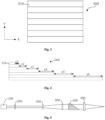
Fig. 1 is a schematic illustration of a homogenization system in an existing laser annealing apparatus. -
Fig. 2 is a schematic illustration of a beam homogenizer for laser annealing according to a first embodiment lying outside the scope of the present invention. -
Fig. 3 is a left view ofFig. 2 . -
Fig. 4 is a schematic illustration of a beam homogenizer for laser annealing according to a second embodiment and according to the present invention. -
Fig. 5 is a schematic illustration of a laser annealing apparatus according to a specific embodiment of the present invention. -
Fig. 6 is a diagram showing an X-directional energy distribution of a light spot obtained by a beam homogenizer for laser annealing -
Fig. 7 is a diagram showing a Y-directional energy distribution of a light spot obtained by a beam homogenizer for laser annealing - In
Fig. 1 : 10-de-coherence system, 11-transparent glass plate, 20-lens array, and 21-cylindrical lens. - In
Figs. 2 to 5 : 100-laser, 200-collimating system, 300-first expander, 400-second expander, 500-beam homogenizer for laser annealing, 510-cylindrical lens, and 600-focusing system. - The purposes, features and advantages of the invention will become more apparent from the following detailed description of several specific embodiments which is to be read in connection with the accompanying drawings. It is noted that the drawings are provided in a very simplified form not necessarily presented to scale, with the only purpose for simplicity and clarity in explaining the embodiments.
- With reference to
Figs. 2 and3 , abeam homogenizer 500 for laser annealing which is incorporated in a laser annealing apparatus, includes a number ofcylindrical lenses 510. Thecylindrical lenses 510 have the same radius of curvature and the same dimensions in a plane of curvature. That is, thecylindrical lenses 510 have the same dimensions of an incident surface (i.e., the same width in an X direction and same thickness in a Y direction). In addition, thecylindrical lenses 510 have different lengths in a Z direction, i.e., the direction of transmission of the beam, and any adjacent two of thecylindrical lenses 510 have a length difference in the direction of transmission of the beam, that is greater than a coherence length of a laser 100 (Fig. 5 ) in the laser annealing apparatus. Replacement of the combination of the transparent glass plates and the cylindrical lenses according to the prior art with the larger-sizedcylindrical lenses 510 according to the present invention can also achieve the de-coherence and homogenization effects while addressing the homogenization-detrimental diffraction problem and resulting in reductions in the complexity of construction of the optical system and cost. - Preferably, with focused reference to
Fig. 5 , the laser annealing apparatus can further include thelaser 100, acollimating system 200, a beam expander system and a focusingsystem 600. In the laser annealing apparatus, along the direction of transmission of the beam, thelaser 100, thecollimating system 200, the beam expander system, thebeam homogenizer 500 and the focusingsystem 600 may be arranged in this sequence. In this arrangement, the beam is emitted from thelaser 100 and is then collimated into a parallel beam by thecollimating system 200. The collimated beam is expanded by the beam expander system to a desired size and is then homogenized by thebeam homogenizer 500. Finally, the homogenized beam passes through the focusingsystem 600 and thereby forms a desired spot on an image plane. - Preferably, the beam expander system may include a
first expander 300 and asecond expander 400. - Outside the scope of the present invention, with focused reference to
Fig. 2 , the length differences between any adjacent two of thecylindrical lenses 510 in the direction of transmission of the beam are fixed values, and the length differences between any adjacent two of thecylindrical lenses 510 in the direction of transmission of the beam are all d, in accordance with this embodiment. - The arrangement of the
cylindrical lenses 510 is not limited to that shown inFig. 2 in which each of thecylindrical lenses 510 is longer than any one of thecylindrical lenses 510 disposed thereabove, because thecylindrical lenses 510 may also be arranged in other ways. - Preferably, the number of the
cylindrical lenses 510 is in the range of from 5 to 7. The 5 to 7cylindrical lenses 510 form a cylindrical-lens array which divides the beam into smaller sub-beams each exiting a respective one of thecylindrical lenses 510 with a certain angle of divergence. After passing through the downstream focusingsystem 600, these sub-beams combine into a homogenized beam which can result in a homogenous light spot with a particular size. As the portions of the beam corresponding to the sub-beams have passed through the differently longcylindrical lenses 510, any adjacent two of which has a length difference that is greater than the coherence length of thelaser 100, the optical path differences among the sub-beams are inconsistent and are all greater than the coherence length. Therefore, there are no longer constant phase differences among the sub-beams that are necessary for the occurrence of coherence among them. That is, elimination of their coherence is achieved, which leads to a better beam homogenization effect. - The radius of curvature of the
cylindrical lenses 510 is between 100 mm and 200 mm and is adjustable according to a desired size of the spot. Each of thecylindrical lenses 510 has a relatively great dimension in the direction of curvature, i.e., the thickness of the cylindrical lens in the Y direction, which is approximately from 4 mm to 10 mm. This dimension can be determined based on a diameter of the beam incident on the cylindrical-lens array and the number of thecylindrical lenses 510. The other dimension of each of thecylindrical lenses 510, i.e., the width of the cylindrical lens in the X direction, is approximately equal to the diameter of the incident beam. Therefore, the dimensions of thecylindrical lenses 510 in the two directions are both determinable by the diameter of the beam incident on the cylindrical-lens array. Further, the curvature of thecylindrical lenses 510 can be determined based on the desired size of the spot and configured to match the dimensions of thecylindrical lenses 510 in the two directions. - Preferably, since the
cylindrical lenses 510 each have a relatively great dimension in the direction of curvature, they can be manufactured by a conventional cold process usually used for the fabrication of optics. This reduces difficulties in the fabrication of the components and thereby results in significant reductions in cost. - With focused reference to
Figs. 6 and 7 , an energy distribution of the formed two-dimensional sport in the untreated X direction (Fig. 6 ), i.e., the direction in which the laser beam has not been homogenized by thebeam homogenizer 500, remains a Gaussian distribution. In contrast, an energy distribution of the two-dimensional sport in the Y direction (i.e., the direction of curvature of the cylindrical lenses 510), in which the de-coherence and homogenization by thecylindrical lenses 510 is applied, as shown inFig. 7 , appears as a truncated curve with a generally flat portion corresponding to a more even energy distribution, demonstrating a good homogenization result of thebeam homogenizer 500 according to the present invention. - According to the invention and with focused reference to
Fig. 4 , this embodiment differs from Embodiment 1 in that, according to this embodiment, the length differences between any two adjacent ones of thecylindrical lenses 510 in the direction of transmission of the beam are different from one another, i.e., inconsistent lengths. In this embodiment, the length differences between any two adjacent ones of thecylindrical lenses 510 in the direction of transmission of the beam are sequentially from the top downward a1, a2, a3, a4, a5 and a6, wherein a1 ≠ a2 ≠ a3 ≠ a4 ≠ as t a6. According to this embodiment, satisfaction of the prerequisite for the occurrence of coherence can also be made impossible and de-coherence can be achieved to result in a better beam homogenization effect. - In summary, the present invention provides a
beam homogenizer 500 for laser annealing, for use in a laser annealing apparatus incorporating alaser 100 for producing a laser beam. Thebeam homogenizer 500 has a number ofcylindrical lenses 510. Thecylindrical lenses 510 have the same radius of curvature and same dimensions in a plane of curvature. In addition, thecylindrical lenses 510 have different lengths in a direction of transmission of the laser beam, and any adjacent two of thecylindrical lenses 510 have a length difference in the direction of transmission of the laser beam, that is greater than a coherence length of thelaser 100. According to the present invention, the differently long, largercylindrical lenses 510 replace the combination of the transparent glass plates and cylindrical lenses according to the prior art, while still achieving de-coherence and homogenization of the laser beam. In addition, diffraction that is detrimental to the homogenization effect can be circumvented, and reductions in the complexity of construction of the optical system and cost can be realized. - It is apparent that those skilled in the art can make various modifications and variations to the present invention without departing from the scope of the invention as defined by the claims. Accordingly, it is intended that the invention embraces all such modifications and variations as fall within the scope of the appended claims.
Claims (4)
- A laser annealing apparatus comprising a beam homogenizer (500) for laser annealing and a laser (100) for producing a laser beam, wherein: the beam homogenizer (500) comprises a plurality of cylindrical lenses (510); the plurality of cylindrical lenses (510) have different lengths in a direction of transmission of the laser beam; wherein
the plurality of cylindrical lenses (510) have a same radius of curvature and same dimensions in a plane of curvature defined by X and Y directions, where the X direction is orthogonal to the Y direction; and characterized in that:
any two adjacent ones of the plurality of cylindrical lenses (510) have a length difference, in the direction of transmission of the laser beam, greater than a coherence length of the laser (100), and in that the length differences between two adjacent ones of the plurality of cylindrical lenses (510) in the direction of transmission of the laser beam differ from one another, the radius of curvature of each of the plurality of cylindrical lenses (510) is from 100 mm to 200 mm, each of the plurality of cylindrical lenses (510) has a thickness in the Y direction of 4 mm to 10 mm, and each of the plurality of cylindrical lenses (510) has a width in the X direction equal to a diameter of the laser beam. - The laser annealing apparatus according to claim 1, wherein: the laser annealing apparatus further comprises a collimating system (200), a beam expander system and a focusing system (600); the laser, the collimating system (200), the beam expander system, the beam homogenizer (500) and the focusing system (600) are disposed in sequence in the direction of transmission of the laser beam in the laser annealing apparatus; and the laser beam produced by the laser (100) is consecutively collimated into a parallel beam by the collimating system (200), expanded to a desired size by the beam expander system and homogenized by the beam homogenizer (500), and then forms a desired spot after passing though the focusing system (600).
- The laser annealing apparatus according to claim 2, wherein a number of the plurality of cylindrical lenses (510) and the dimensions of the plurality of cylindrical lenses (510) in the plane of curvature are determined by the diameter of the laser beam incident on the beam homogenizer (500).
- The laser annealing apparatus according to claim 1, wherein the number of the plurality of cylindrical lenses (510) is from 5 to 7.
Applications Claiming Priority (2)
| Application Number | Priority Date | Filing Date | Title |
|---|---|---|---|
| CN201410043852.9A CN104808343B (en) | 2014-01-29 | 2014-01-29 | A kind of laser annealing dodging device |
| PCT/CN2015/070747 WO2015113469A1 (en) | 2014-01-29 | 2015-01-15 | Laser annealing dodging apparatus |
Publications (3)
| Publication Number | Publication Date |
|---|---|
| EP3101463A1 EP3101463A1 (en) | 2016-12-07 |
| EP3101463A4 EP3101463A4 (en) | 2017-01-18 |
| EP3101463B1 true EP3101463B1 (en) | 2024-09-04 |
Family
ID=53693308
Family Applications (1)
| Application Number | Title | Priority Date | Filing Date |
|---|---|---|---|
| EP15742551.3A Active EP3101463B1 (en) | 2014-01-29 | 2015-01-15 | Laser annealing apparatus |
Country Status (7)
| Country | Link |
|---|---|
| EP (1) | EP3101463B1 (en) |
| JP (1) | JP6531107B2 (en) |
| KR (1) | KR101918252B1 (en) |
| CN (1) | CN104808343B (en) |
| SG (1) | SG11201606160RA (en) |
| TW (1) | TWI584904B (en) |
| WO (1) | WO2015113469A1 (en) |
Families Citing this family (9)
| Publication number | Priority date | Publication date | Assignee | Title |
|---|---|---|---|---|
| CN106646716A (en) * | 2017-02-14 | 2017-05-10 | 山西大学 | Space stacking light beam distributed phase delayer and speckle elimination method thereof |
| JP2018195676A (en) * | 2017-05-16 | 2018-12-06 | 株式会社ブイ・テクノロジー | Laser annealing apparatus and laser annealing method |
| KR102467462B1 (en) * | 2017-12-05 | 2022-11-16 | 삼성디스플레이 주식회사 | Laser crystallization apparatus |
| CN111383916A (en) * | 2018-12-28 | 2020-07-07 | 上海微电子装备(集团)股份有限公司 | Laser annealing device for SiC substrate |
| CN111061062B (en) * | 2020-01-09 | 2021-05-11 | 山西大学 | A kind of laser speckle suppression element and suppression method |
| FR3113428B1 (en) * | 2020-08-14 | 2022-08-19 | Imagine Optic | Methods and systems for generating high peak power laser pulses |
| KR20220099192A (en) | 2021-01-05 | 2022-07-13 | 삼성디스플레이 주식회사 | Laser crystallization apparatus |
| CN115585987A (en) * | 2022-09-27 | 2023-01-10 | 中国工程物理研究院激光聚变研究中心 | A transmission element polarization performance detection system and detection method |
| CN116184681B (en) * | 2023-04-27 | 2023-08-04 | 成都莱普科技股份有限公司 | Beam shaping device and beam shaping method for carbon dioxide laser |
Citations (3)
| Publication number | Priority date | Publication date | Assignee | Title |
|---|---|---|---|---|
| JP2006049656A (en) * | 2004-08-06 | 2006-02-16 | Japan Steel Works Ltd:The | Method and apparatus for forming crystallized film |
| DE202006007691U1 (en) * | 2006-05-13 | 2006-08-24 | Coherent Lambda Physik Gmbh | Laser beam homogenizing device for e.g. laser ablation, has cylindrical lens dividing laser beam into partial beams, where path length difference of two of partial beams is larger than temporal coherence length of laser beam |
| US20100033829A1 (en) * | 2006-10-10 | 2010-02-11 | Fraunhofer-Gesellschaft zur Förderung der angewandten Forschung e.V. | Device for Homogenizing Radiation by Means of Irregular Microlens Arrays |
Family Cites Families (16)
| Publication number | Priority date | Publication date | Assignee | Title |
|---|---|---|---|---|
| JPH0721583B2 (en) * | 1985-01-22 | 1995-03-08 | 株式会社ニコン | Exposure equipment |
| US5963305A (en) * | 1996-09-12 | 1999-10-05 | Canon Kabushiki Kaisha | Illumination system and exposure apparatus |
| US6898216B1 (en) * | 1999-06-30 | 2005-05-24 | Lambda Physik Ag | Reduction of laser speckle in photolithography by controlled disruption of spatial coherence of laser beam |
| US6069739A (en) * | 1998-06-30 | 2000-05-30 | Intel Corporation | Method and lens arrangement to improve imaging performance of microlithography exposure tool |
| TW523791B (en) * | 2000-09-01 | 2003-03-11 | Semiconductor Energy Lab | Method of processing beam, laser irradiation apparatus, and method of manufacturing semiconductor device |
| JP3969197B2 (en) * | 2002-06-06 | 2007-09-05 | 石川島播磨重工業株式会社 | Laser irradiation device |
| JP2004200497A (en) * | 2002-12-19 | 2004-07-15 | Sony Corp | Light irradiation device and laser annealing device |
| US7521651B2 (en) * | 2003-09-12 | 2009-04-21 | Orbotech Ltd | Multiple beam micro-machining system and method |
| JP2007214527A (en) * | 2006-01-13 | 2007-08-23 | Ihi Corp | Laser annealing method and laser annealing apparatus |
| EP2128694B1 (en) * | 2007-03-19 | 2014-02-26 | Panasonic Corporation | Laser illuminating device and image display device |
| JP2008294186A (en) * | 2007-05-24 | 2008-12-04 | Shimadzu Corp | Crystallization apparatus and crystallization method |
| WO2009150733A1 (en) * | 2008-06-12 | 2009-12-17 | 株式会社Ihi | Laser annealing method and laser annealing apparatus |
| TW201001555A (en) * | 2008-06-17 | 2010-01-01 | Ihi Corp | Laser anneal method and laser anneal device |
| JP2012518791A (en) * | 2009-02-23 | 2012-08-16 | ディメンジョナル フォトニクス インターナショナル,インコーポレイテッド | Speckle noise reduction in coherent illumination imaging systems |
| DE102009037141B4 (en) * | 2009-07-31 | 2013-01-03 | Carl Zeiss Laser Optics Gmbh | Optical system for generating a light beam for treating a substrate |
| CN104752267B (en) * | 2013-12-31 | 2018-04-27 | 上海微电子装备(集团)股份有限公司 | A kind of laser anneal device and method |
-
2014
- 2014-01-29 CN CN201410043852.9A patent/CN104808343B/en active Active
-
2015
- 2015-01-15 SG SG11201606160RA patent/SG11201606160RA/en unknown
- 2015-01-15 JP JP2016549057A patent/JP6531107B2/en active Active
- 2015-01-15 EP EP15742551.3A patent/EP3101463B1/en active Active
- 2015-01-15 WO PCT/CN2015/070747 patent/WO2015113469A1/en not_active Ceased
- 2015-01-15 KR KR1020167022637A patent/KR101918252B1/en active Active
- 2015-01-26 TW TW104102507A patent/TWI584904B/en active
Patent Citations (3)
| Publication number | Priority date | Publication date | Assignee | Title |
|---|---|---|---|---|
| JP2006049656A (en) * | 2004-08-06 | 2006-02-16 | Japan Steel Works Ltd:The | Method and apparatus for forming crystallized film |
| DE202006007691U1 (en) * | 2006-05-13 | 2006-08-24 | Coherent Lambda Physik Gmbh | Laser beam homogenizing device for e.g. laser ablation, has cylindrical lens dividing laser beam into partial beams, where path length difference of two of partial beams is larger than temporal coherence length of laser beam |
| US20100033829A1 (en) * | 2006-10-10 | 2010-02-11 | Fraunhofer-Gesellschaft zur Förderung der angewandten Forschung e.V. | Device for Homogenizing Radiation by Means of Irregular Microlens Arrays |
Also Published As
| Publication number | Publication date |
|---|---|
| TW201540408A (en) | 2015-11-01 |
| JP6531107B2 (en) | 2019-06-12 |
| KR20160111467A (en) | 2016-09-26 |
| KR101918252B1 (en) | 2018-11-13 |
| EP3101463A1 (en) | 2016-12-07 |
| EP3101463A4 (en) | 2017-01-18 |
| WO2015113469A1 (en) | 2015-08-06 |
| CN104808343A (en) | 2015-07-29 |
| JP2017510975A (en) | 2017-04-13 |
| CN104808343B (en) | 2018-03-30 |
| SG11201606160RA (en) | 2016-09-29 |
| TWI584904B (en) | 2017-06-01 |
Similar Documents
| Publication | Publication Date | Title |
|---|---|---|
| EP3101463A1 (en) | Laser annealing dodging apparatus | |
| US6943086B2 (en) | Laser annealing apparatus, TFT device and annealing method of the same | |
| KR101647279B1 (en) | Optical design for line generation using microlens array | |
| KR101242094B1 (en) | Laser anneal method and device | |
| US7964035B2 (en) | Crystallization apparatus and crystallization method | |
| KR101227803B1 (en) | Homogenizer with reduced interference | |
| EP0905540A2 (en) | Beam homogenizer, laser illumination apparatus and method, and semiconductor device | |
| KR102483322B1 (en) | Polarization module and laser irradiation apparatus including the same | |
| KR20100065326A (en) | Method and arrangement for producing a laser beam with a linear beam cross section | |
| KR20080102933A (en) | Crystallization Apparatus and Crystallization Method | |
| TW200400672A (en) | An optical system for uniformly irradiating a laser bear | |
| KR101073555B1 (en) | Laser irradiation apparatus, irradiation method thereof and crystalizing method of amorphous silicon film using the same | |
| WO2019044303A1 (en) | Laser annealing device and laser annealing method | |
| US11600491B2 (en) | Laser apparatus and method of processing thin films | |
| US20190287790A1 (en) | Laser irradiation apparatus and method of manufacturing thin film transistor | |
| KR102914553B1 (en) | Diffuser_based optical system for laser beam homogenization and laser annealing device including the same | |
| KR102796148B1 (en) | Silicon crystallization apparatus | |
| KR102933257B1 (en) | Laser Irradiation Apparatus and Polarization Control Module and Method Used Therein | |
| KR102804137B1 (en) | Laser beam homogenizer using birefringent prism and laser annealing device including the same | |
| US20050134964A1 (en) | Laser optical system for liquid crystal display device | |
| KR101928264B1 (en) | Laser beam shaping apparatus | |
| US8853062B2 (en) | Laser crystallization apparatus and laser crystallization method using the apparatus | |
| JP2003287705A (en) | Laser beam uniform irradiation optical system | |
| JP2018133417A (en) | Laser illumination device and line beam laser irradiation device | |
| JP2002367923A (en) | Laser beam irradiation method and apparatus |
Legal Events
| Date | Code | Title | Description |
|---|---|---|---|
| PUAI | Public reference made under article 153(3) epc to a published international application that has entered the european phase |
Free format text: ORIGINAL CODE: 0009012 |
|
| STAA | Information on the status of an ep patent application or granted ep patent |
Free format text: STATUS: REQUEST FOR EXAMINATION WAS MADE |
|
| 17P | Request for examination filed |
Effective date: 20160818 |
|
| AK | Designated contracting states |
Kind code of ref document: A1 Designated state(s): AL AT BE BG CH CY CZ DE DK EE ES FI FR GB GR HR HU IE IS IT LI LT LU LV MC MK MT NL NO PL PT RO RS SE SI SK SM TR |
|
| AX | Request for extension of the european patent |
Extension state: BA ME |
|
| A4 | Supplementary search report drawn up and despatched |
Effective date: 20161220 |
|
| RIC1 | Information provided on ipc code assigned before grant |
Ipc: G02B 3/00 20060101ALI20161214BHEP Ipc: G02B 27/48 20060101AFI20161214BHEP Ipc: G03F 7/20 20060101ALI20161214BHEP |
|
| DAX | Request for extension of the european patent (deleted) | ||
| RAP1 | Party data changed (applicant data changed or rights of an application transferred) |
Owner name: SHANGHAI MICRO ELECTRONICS EQUIPMENT (GROUP) CO., |
|
| STAA | Information on the status of an ep patent application or granted ep patent |
Free format text: STATUS: EXAMINATION IS IN PROGRESS |
|
| 17Q | First examination report despatched |
Effective date: 20210215 |
|
| GRAP | Despatch of communication of intention to grant a patent |
Free format text: ORIGINAL CODE: EPIDOSNIGR1 |
|
| STAA | Information on the status of an ep patent application or granted ep patent |
Free format text: STATUS: GRANT OF PATENT IS INTENDED |
|
| INTG | Intention to grant announced |
Effective date: 20240425 |
|
| GRAS | Grant fee paid |
Free format text: ORIGINAL CODE: EPIDOSNIGR3 |
|
| GRAA | (expected) grant |
Free format text: ORIGINAL CODE: 0009210 |
|
| STAA | Information on the status of an ep patent application or granted ep patent |
Free format text: STATUS: THE PATENT HAS BEEN GRANTED |
|
| AK | Designated contracting states |
Kind code of ref document: B1 Designated state(s): AL AT BE BG CH CY CZ DE DK EE ES FI FR GB GR HR HU IE IS IT LI LT LU LV MC MK MT NL NO PL PT RO RS SE SI SK SM TR |
|
| REG | Reference to a national code |
Ref country code: GB Ref legal event code: FG4D |
|
| REG | Reference to a national code |
Ref country code: CH Ref legal event code: EP |
|
| REG | Reference to a national code |
Ref country code: IE Ref legal event code: FG4D |
|
| REG | Reference to a national code |
Ref country code: DE Ref legal event code: R096 Ref document number: 602015089769 Country of ref document: DE |
|
| REG | Reference to a national code |
Ref country code: LT Ref legal event code: MG9D |
|
| REG | Reference to a national code |
Ref country code: NL Ref legal event code: MP Effective date: 20240904 |
|
| PG25 | Lapsed in a contracting state [announced via postgrant information from national office to epo] |
Ref country code: NO Free format text: LAPSE BECAUSE OF FAILURE TO SUBMIT A TRANSLATION OF THE DESCRIPTION OR TO PAY THE FEE WITHIN THE PRESCRIBED TIME-LIMIT Effective date: 20241204 |
|
| PG25 | Lapsed in a contracting state [announced via postgrant information from national office to epo] |
Ref country code: PL Free format text: LAPSE BECAUSE OF FAILURE TO SUBMIT A TRANSLATION OF THE DESCRIPTION OR TO PAY THE FEE WITHIN THE PRESCRIBED TIME-LIMIT Effective date: 20240904 Ref country code: GR Free format text: LAPSE BECAUSE OF FAILURE TO SUBMIT A TRANSLATION OF THE DESCRIPTION OR TO PAY THE FEE WITHIN THE PRESCRIBED TIME-LIMIT Effective date: 20241205 Ref country code: FI Free format text: LAPSE BECAUSE OF FAILURE TO SUBMIT A TRANSLATION OF THE DESCRIPTION OR TO PAY THE FEE WITHIN THE PRESCRIBED TIME-LIMIT Effective date: 20240904 |
|
| PG25 | Lapsed in a contracting state [announced via postgrant information from national office to epo] |
Ref country code: BG Free format text: LAPSE BECAUSE OF FAILURE TO SUBMIT A TRANSLATION OF THE DESCRIPTION OR TO PAY THE FEE WITHIN THE PRESCRIBED TIME-LIMIT Effective date: 20240904 |
|
| PG25 | Lapsed in a contracting state [announced via postgrant information from national office to epo] |
Ref country code: LV Free format text: LAPSE BECAUSE OF FAILURE TO SUBMIT A TRANSLATION OF THE DESCRIPTION OR TO PAY THE FEE WITHIN THE PRESCRIBED TIME-LIMIT Effective date: 20240904 |
|
| PG25 | Lapsed in a contracting state [announced via postgrant information from national office to epo] |
Ref country code: HR Free format text: LAPSE BECAUSE OF FAILURE TO SUBMIT A TRANSLATION OF THE DESCRIPTION OR TO PAY THE FEE WITHIN THE PRESCRIBED TIME-LIMIT Effective date: 20240904 |
|
| PG25 | Lapsed in a contracting state [announced via postgrant information from national office to epo] |
Ref country code: ES Free format text: LAPSE BECAUSE OF FAILURE TO SUBMIT A TRANSLATION OF THE DESCRIPTION OR TO PAY THE FEE WITHIN THE PRESCRIBED TIME-LIMIT Effective date: 20240904 Ref country code: RS Free format text: LAPSE BECAUSE OF FAILURE TO SUBMIT A TRANSLATION OF THE DESCRIPTION OR TO PAY THE FEE WITHIN THE PRESCRIBED TIME-LIMIT Effective date: 20241204 |
|
| PG25 | Lapsed in a contracting state [announced via postgrant information from national office to epo] |
Ref country code: RS Free format text: LAPSE BECAUSE OF FAILURE TO SUBMIT A TRANSLATION OF THE DESCRIPTION OR TO PAY THE FEE WITHIN THE PRESCRIBED TIME-LIMIT Effective date: 20241204 Ref country code: PL Free format text: LAPSE BECAUSE OF FAILURE TO SUBMIT A TRANSLATION OF THE DESCRIPTION OR TO PAY THE FEE WITHIN THE PRESCRIBED TIME-LIMIT Effective date: 20240904 Ref country code: NO Free format text: LAPSE BECAUSE OF FAILURE TO SUBMIT A TRANSLATION OF THE DESCRIPTION OR TO PAY THE FEE WITHIN THE PRESCRIBED TIME-LIMIT Effective date: 20241204 Ref country code: LV Free format text: LAPSE BECAUSE OF FAILURE TO SUBMIT A TRANSLATION OF THE DESCRIPTION OR TO PAY THE FEE WITHIN THE PRESCRIBED TIME-LIMIT Effective date: 20240904 Ref country code: HR Free format text: LAPSE BECAUSE OF FAILURE TO SUBMIT A TRANSLATION OF THE DESCRIPTION OR TO PAY THE FEE WITHIN THE PRESCRIBED TIME-LIMIT Effective date: 20240904 Ref country code: GR Free format text: LAPSE BECAUSE OF FAILURE TO SUBMIT A TRANSLATION OF THE DESCRIPTION OR TO PAY THE FEE WITHIN THE PRESCRIBED TIME-LIMIT Effective date: 20241205 Ref country code: FI Free format text: LAPSE BECAUSE OF FAILURE TO SUBMIT A TRANSLATION OF THE DESCRIPTION OR TO PAY THE FEE WITHIN THE PRESCRIBED TIME-LIMIT Effective date: 20240904 Ref country code: ES Free format text: LAPSE BECAUSE OF FAILURE TO SUBMIT A TRANSLATION OF THE DESCRIPTION OR TO PAY THE FEE WITHIN THE PRESCRIBED TIME-LIMIT Effective date: 20240904 Ref country code: BG Free format text: LAPSE BECAUSE OF FAILURE TO SUBMIT A TRANSLATION OF THE DESCRIPTION OR TO PAY THE FEE WITHIN THE PRESCRIBED TIME-LIMIT Effective date: 20240904 |
|
| REG | Reference to a national code |
Ref country code: AT Ref legal event code: MK05 Ref document number: 1720987 Country of ref document: AT Kind code of ref document: T Effective date: 20240904 |
|
| PG25 | Lapsed in a contracting state [announced via postgrant information from national office to epo] |
Ref country code: NL Free format text: LAPSE BECAUSE OF FAILURE TO SUBMIT A TRANSLATION OF THE DESCRIPTION OR TO PAY THE FEE WITHIN THE PRESCRIBED TIME-LIMIT Effective date: 20240904 |
|
| PG25 | Lapsed in a contracting state [announced via postgrant information from national office to epo] |
Ref country code: PT Free format text: LAPSE BECAUSE OF FAILURE TO SUBMIT A TRANSLATION OF THE DESCRIPTION OR TO PAY THE FEE WITHIN THE PRESCRIBED TIME-LIMIT Effective date: 20250106 Ref country code: IS Free format text: LAPSE BECAUSE OF FAILURE TO SUBMIT A TRANSLATION OF THE DESCRIPTION OR TO PAY THE FEE WITHIN THE PRESCRIBED TIME-LIMIT Effective date: 20250104 |
|
| PG25 | Lapsed in a contracting state [announced via postgrant information from national office to epo] |
Ref country code: RO Free format text: LAPSE BECAUSE OF FAILURE TO SUBMIT A TRANSLATION OF THE DESCRIPTION OR TO PAY THE FEE WITHIN THE PRESCRIBED TIME-LIMIT Effective date: 20240904 Ref country code: SM Free format text: LAPSE BECAUSE OF FAILURE TO SUBMIT A TRANSLATION OF THE DESCRIPTION OR TO PAY THE FEE WITHIN THE PRESCRIBED TIME-LIMIT Effective date: 20240904 |
|
| PG25 | Lapsed in a contracting state [announced via postgrant information from national office to epo] |
Ref country code: EE Free format text: LAPSE BECAUSE OF FAILURE TO SUBMIT A TRANSLATION OF THE DESCRIPTION OR TO PAY THE FEE WITHIN THE PRESCRIBED TIME-LIMIT Effective date: 20240904 Ref country code: AT Free format text: LAPSE BECAUSE OF FAILURE TO SUBMIT A TRANSLATION OF THE DESCRIPTION OR TO PAY THE FEE WITHIN THE PRESCRIBED TIME-LIMIT Effective date: 20240904 |
|
| PG25 | Lapsed in a contracting state [announced via postgrant information from national office to epo] |
Ref country code: CZ Free format text: LAPSE BECAUSE OF FAILURE TO SUBMIT A TRANSLATION OF THE DESCRIPTION OR TO PAY THE FEE WITHIN THE PRESCRIBED TIME-LIMIT Effective date: 20240904 |
|
| PG25 | Lapsed in a contracting state [announced via postgrant information from national office to epo] |
Ref country code: IT Free format text: LAPSE BECAUSE OF FAILURE TO SUBMIT A TRANSLATION OF THE DESCRIPTION OR TO PAY THE FEE WITHIN THE PRESCRIBED TIME-LIMIT Effective date: 20240904 Ref country code: SK Free format text: LAPSE BECAUSE OF FAILURE TO SUBMIT A TRANSLATION OF THE DESCRIPTION OR TO PAY THE FEE WITHIN THE PRESCRIBED TIME-LIMIT Effective date: 20240904 |
|
| REG | Reference to a national code |
Ref country code: DE Ref legal event code: R097 Ref document number: 602015089769 Country of ref document: DE |
|
| PG25 | Lapsed in a contracting state [announced via postgrant information from national office to epo] |
Ref country code: DK Free format text: LAPSE BECAUSE OF FAILURE TO SUBMIT A TRANSLATION OF THE DESCRIPTION OR TO PAY THE FEE WITHIN THE PRESCRIBED TIME-LIMIT Effective date: 20240904 |
|
| PLBE | No opposition filed within time limit |
Free format text: ORIGINAL CODE: 0009261 |
|
| STAA | Information on the status of an ep patent application or granted ep patent |
Free format text: STATUS: NO OPPOSITION FILED WITHIN TIME LIMIT |
|
| 26N | No opposition filed |
Effective date: 20250605 |
|
| REG | Reference to a national code |
Ref country code: CH Ref legal event code: PL |
|
| REG | Reference to a national code |
Ref country code: DE Ref legal event code: R081 Ref document number: 602015089769 Country of ref document: DE Owner name: AMIES TECHNOLOGY CO., LTD., CN Free format text: FORMER OWNER: SHANGHAI MICRO ELECTRONICS EQUIPMENT (GROUP) CO., LTD., SHANGHAI, CN |
|
| PG25 | Lapsed in a contracting state [announced via postgrant information from national office to epo] |
Ref country code: SE Free format text: LAPSE BECAUSE OF FAILURE TO SUBMIT A TRANSLATION OF THE DESCRIPTION OR TO PAY THE FEE WITHIN THE PRESCRIBED TIME-LIMIT Effective date: 20240904 |
|
| PG25 | Lapsed in a contracting state [announced via postgrant information from national office to epo] |
Ref country code: LU Free format text: LAPSE BECAUSE OF NON-PAYMENT OF DUE FEES Effective date: 20250115 Ref country code: MC Free format text: LAPSE BECAUSE OF FAILURE TO SUBMIT A TRANSLATION OF THE DESCRIPTION OR TO PAY THE FEE WITHIN THE PRESCRIBED TIME-LIMIT Effective date: 20240904 |
|
| REG | Reference to a national code |
Ref country code: GB Ref legal event code: 732E Free format text: REGISTERED BETWEEN 20250918 AND 20250924 |
|
| PG25 | Lapsed in a contracting state [announced via postgrant information from national office to epo] |
Ref country code: BE Free format text: LAPSE BECAUSE OF NON-PAYMENT OF DUE FEES Effective date: 20250131 |
|
| PG25 | Lapsed in a contracting state [announced via postgrant information from national office to epo] |
Ref country code: FR Free format text: LAPSE BECAUSE OF NON-PAYMENT OF DUE FEES Effective date: 20250131 |
|
| PG25 | Lapsed in a contracting state [announced via postgrant information from national office to epo] |
Ref country code: CH Free format text: LAPSE BECAUSE OF NON-PAYMENT OF DUE FEES Effective date: 20250131 |
|
| REG | Reference to a national code |
Ref country code: BE Ref legal event code: MM Effective date: 20250131 |
|
| PGFP | Annual fee paid to national office [announced via postgrant information from national office to epo] |
Ref country code: GB Payment date: 20251117 Year of fee payment: 12 |
|
| PG25 | Lapsed in a contracting state [announced via postgrant information from national office to epo] |
Ref country code: IE Free format text: LAPSE BECAUSE OF NON-PAYMENT OF DUE FEES Effective date: 20250115 |
|
| PGFP | Annual fee paid to national office [announced via postgrant information from national office to epo] |
Ref country code: DE Payment date: 20260120 Year of fee payment: 12 |
|
| PG25 | Lapsed in a contracting state [announced via postgrant information from national office to epo] |
Ref country code: CY Free format text: LAPSE BECAUSE OF FAILURE TO SUBMIT A TRANSLATION OF THE DESCRIPTION OR TO PAY THE FEE WITHIN THE PRESCRIBED TIME-LIMIT Effective date: 20240904 |
|
| PG25 | Lapsed in a contracting state [announced via postgrant information from national office to epo] |
Ref country code: TR Free format text: LAPSE BECAUSE OF FAILURE TO SUBMIT A TRANSLATION OF THE DESCRIPTION OR TO PAY THE FEE WITHIN THE PRESCRIBED TIME-LIMIT Effective date: 20240904 |
|
| PG25 | Lapsed in a contracting state [announced via postgrant information from national office to epo] |
Ref country code: LT Free format text: LAPSE BECAUSE OF FAILURE TO SUBMIT A TRANSLATION OF THE DESCRIPTION OR TO PAY THE FEE WITHIN THE PRESCRIBED TIME-LIMIT Effective date: 20240904 |