EP3101328A1 - Werkzeugmaschine - Google Patents
Werkzeugmaschine Download PDFInfo
- Publication number
- EP3101328A1 EP3101328A1 EP16170588.4A EP16170588A EP3101328A1 EP 3101328 A1 EP3101328 A1 EP 3101328A1 EP 16170588 A EP16170588 A EP 16170588A EP 3101328 A1 EP3101328 A1 EP 3101328A1
- Authority
- EP
- European Patent Office
- Prior art keywords
- machine tool
- coil
- protective device
- bolt
- machine
- Prior art date
- Legal status (The legal status is an assumption and is not a legal conclusion. Google has not performed a legal analysis and makes no representation as to the accuracy of the status listed.)
- Granted
Links
Images

Classifications
-
- F—MECHANICAL ENGINEERING; LIGHTING; HEATING; WEAPONS; BLASTING
- F16—ENGINEERING ELEMENTS AND UNITS; GENERAL MEASURES FOR PRODUCING AND MAINTAINING EFFECTIVE FUNCTIONING OF MACHINES OR INSTALLATIONS; THERMAL INSULATION IN GENERAL
- F16P—SAFETY DEVICES IN GENERAL; SAFETY DEVICES FOR PRESSES
- F16P3/00—Safety devices acting in conjunction with the control or operation of a machine; Control arrangements requiring the simultaneous use of two or more parts of the body
- F16P3/08—Safety devices acting in conjunction with the control or operation of a machine; Control arrangements requiring the simultaneous use of two or more parts of the body in connection with the locking of doors, covers, guards, or like members giving access to moving machine parts
-
- B—PERFORMING OPERATIONS; TRANSPORTING
- B23—MACHINE TOOLS; METAL-WORKING NOT OTHERWISE PROVIDED FOR
- B23Q—DETAILS, COMPONENTS, OR ACCESSORIES FOR MACHINE TOOLS, e.g. ARRANGEMENTS FOR COPYING OR CONTROLLING; MACHINE TOOLS IN GENERAL CHARACTERISED BY THE CONSTRUCTION OF PARTICULAR DETAILS OR COMPONENTS; COMBINATIONS OR ASSOCIATIONS OF METAL-WORKING MACHINES, NOT DIRECTED TO A PARTICULAR RESULT
- B23Q11/00—Accessories fitted to machine tools for keeping tools or parts of the machine in good working condition or for cooling work; Safety devices specially combined with or arranged in, or specially adapted for use in connection with, machine tools
- B23Q11/0078—Safety devices protecting the operator, e.g. against accident or noise
-
- B—PERFORMING OPERATIONS; TRANSPORTING
- B23—MACHINE TOOLS; METAL-WORKING NOT OTHERWISE PROVIDED FOR
- B23Q—DETAILS, COMPONENTS, OR ACCESSORIES FOR MACHINE TOOLS, e.g. ARRANGEMENTS FOR COPYING OR CONTROLLING; MACHINE TOOLS IN GENERAL CHARACTERISED BY THE CONSTRUCTION OF PARTICULAR DETAILS OR COMPONENTS; COMBINATIONS OR ASSOCIATIONS OF METAL-WORKING MACHINES, NOT DIRECTED TO A PARTICULAR RESULT
- B23Q11/00—Accessories fitted to machine tools for keeping tools or parts of the machine in good working condition or for cooling work; Safety devices specially combined with or arranged in, or specially adapted for use in connection with, machine tools
- B23Q11/08—Protective coverings for parts of machine tools; Splash guards
- B23Q11/0891—Protective coverings for parts of machine tools; Splash guards arranged between the working area and the operator
-
- F—MECHANICAL ENGINEERING; LIGHTING; HEATING; WEAPONS; BLASTING
- F16—ENGINEERING ELEMENTS AND UNITS; GENERAL MEASURES FOR PRODUCING AND MAINTAINING EFFECTIVE FUNCTIONING OF MACHINES OR INSTALLATIONS; THERMAL INSULATION IN GENERAL
- F16P—SAFETY DEVICES IN GENERAL; SAFETY DEVICES FOR PRESSES
- F16P1/00—Safety devices independent of the control and operation of any machine
- F16P1/02—Fixed screens or hoods
Definitions
- the present invention relates to a machine tool for processing plate-shaped workpieces, which are preferably at least partially made of wood, wood-based materials or plastics, with a locking system for a protective device.
- machining workpieces which consist for example of wood, wood materials, plastics or the like, used to date for security access control devices, such as protective doors , mechanical locking elements or optical sensors.
- security access control devices such as protective doors , mechanical locking elements or optical sensors.
- a machine tool with locking system for safety doors with the features of the preamble of claim 1, characterized in that one engages a retractable in the machine floor bolt, preferably a cylinder, which engages in a locking receptacle, an opening in a closable part, on the protective device ,
- the lid surface of the bolt lies in a plane with the machine floor or below.
- the machine base thus has a planar or a depression in the planar surface on which no Objects or parts protrude into the processing room.
- This special design greatly reduces the risk of injury to the operator as he no longer risks stumbling or hanging when entering the machine, for example when changing tools.
- these no longer start thereby reducing the production committee is achieved.
- the low probability of failure is achieved by the small number of components and their closed design, for the bolt, and the open design, for the part to be closed. By avoiding chambers and undercuts, no parts can accumulate in these areas and a malfunction due to clogging is avoided. In addition, by lowering the bolt, this by an operator or a workpiece, for example by against it, no longer can be damaged or bent and thereby the life increases and the probability of failure decreases.
- the bolt is moved to open and close the protective device in an angle to the bottom surface direction, for example along the longitudinal axis of the cylinder.
- This axis extends in an angle to the bottom surface, ie not parallel to this.
- the lifting height of the bolt is between the unlocking position, which is characterized in that the lid surface of the bolt is in a plane with the machine floor (or below), and the locking position, which is characterized in that the bolt engages in the closable part and the Lid surface of the bolt over the end surface of the closable part or the opening protrudes.
- the machine tool has a closable part, which can be made in various ways.
- the closable part can be designed so that it represents an inverted U-profile, engages in the open leg of the bolt and pointing down, towards the machine floor.
- the two lateral legs of the profile need not be the same length, but may be due to constructive and safety measures of varying lengths.
- the planes in which the two legs lie should preferably be parallel to each other.
- this profile can be used, which by means of the two legs, which in this case are arranged perpendicular to the direction of movement, securely embeds the bolt in the direction of movement of the protective device and thereby mechanically locks the protective device.
- the wearable part can also be represented by a component with a correspondingly large hole.
- another leg usually the fourth side in a rectangle, is inserted and fixed in the part to be closed.
- This leg is parallel to the machine floor and sits between the two parallel side legs.
- the attachment can be done for example by welding, gluing, flanging, or by a positive connection.
- the new leg is an opening, preferably a hole or hole, which has a larger circumference than the circumference of the bolt.
- this profile can be used, which securely engages the bolt, for example, through the bore Movement direction of the protective device embeds and thereby mechanically locks the protective device.
- the machine tool has a protective device.
- This can be designed as a hood, door, flap or any other closable element that protects the operator from noise, flying parts, such as chips, cutters or lubricants, and dust.
- a protective device can be designed as a hood, door, flap or any other closable element that protects the operator from noise, flying parts, such as chips, cutters or lubricants, and dust.
- the machine tool not only has a mechanical safety device but also an electronic one.
- Electronic monitoring is made possible by the mutual use of active and passive coils and power and evaluation electronics. This has the advantage that a part, the passive coil or transponder, always acts only as a reflector and so the maintenance work and failures can be kept to a minimum.
- an active or passive coil is arranged according to an embodiment of the invention in the bar of the machine tool.
- a space is created on the lid surface of the bolt, for example by turning or milling, in which this coil can be used.
- the coil is used there.
- the epoxy resin in this case has the advantage that the antenna effect with respect to the interfering metal / environment does not come into effect.
- an active coil also referred to as a reader
- the latch must additionally be equipped with a channel that can guide the cables of the coil to the power and evaluation electronics.
- the Bar consist of a solid material or a piston rod with hollow bore. Due to the variability, the locking system can be adapted to various machine tools that already have electronic monitoring.
- the machine tool not only has the bolt, but also the lockable part on active or passive coil, which serves as a counterpart of the coil in the bolt and thus for determining the position of the protective device.
- active coil i. a reader
- passive coil i. a transponder
- the coil is fastened, for example, with an adhesive or with another fastening element.
- the active coil may detect a change in the position of the passive coil.
- the locking position must be achieved, but is allowed between the coils used, or components, an offset in space within predetermined tolerances.
- the latch of the locking system is extended and retracted or moved to an unlocking and locking position.
- This movement is preferably pneumatic, but can also be performed hydraulically, electrically, magnetically or mechanically.
- the two coils are monitored by the power and evaluation unit. This is set up so that it only releases the operation of the machine when the first and the second coil are in a position to each other, in which it is ensured that the protective device is also properly closed.
- This system is preferably a transceiver system or RFID system.
- the active coil becomes each programmed and coded, so that an unambiguous assignment to a passive coil can take place. This can be a standard encoding or a special encoding. If a spool breaks, the default coding can simply replace the broken part without having to recode it. However, if the coils are provided with special coding, the system or the two coils must be replaced together. This has the advantage that improper bridging of the security systems is prevented. In addition, no components of lower quality can be installed.
- FIG. 1 shows a cross-sectional view, according to an embodiment of the invention, a machine tool 1, which comprises a processing space 2, a protective device 10 and a machine tool main body 20.
- a coordinate system which has its origin in the plane of a machine base 21 of the machine tool 1.
- the X-axis is orthogonal on the machine base 21 and extends upward, in the direction of the processing space 2.
- the Y-axis lies in the plane of the machine base 21 and is orthogonal to the X-axis and the protection device 10.
- the Y-axis in the direction of the rear part of the machine tool 1, that is to say it points away from the protective device 10.
- the Z axis lies orthogonal to the Y and X axes and points out of the plane of the drawing.
- the processing space 2 is the space in which the workpieces are processed by means of the tool of the machine tool 1. This area is delimited by the public area 3, in which, for example, the operators 3 are located, by a protective device 10.
- the protection device 10 can be removed or opened.
- FIG. 1 shows and shows a folding mechanism with which a machine flap 12 is folded upwards.
- the joint is attached to the top end of the machine tool 1, so that the machine flap 12 can rotate about a Z 'axis (rotation axis in the joint and parallel to the Z axis).
- this mechanism can be replaced, for example, by a protective device 10 with a displaceable machine flap 12.
- the machine flap 12 is then mounted on a linear guide, which is located at the top or bottom of the flap 12.
- the flap 12 moves when opening or closing the guard 10 parallel to the Z-axis.
- a closable part 13 is attached according to the invention. This part is shown schematically in the magnification area B and is explained in more detail in the following illustrations.
- the closable part 13 can be embodied in various embodiments, which are described in more detail below.
- the machine tool main body 20 includes, inter alia, the machine base 21 and a schematically illustrated bar 22.
- the various embodiments and a detailed representation are also made here for clarity in the following illustrations and embodiments.
- the longitudinal sectional view of the enlargement area B in FIG. 2 shows a first embodiment B 'of the invention.
- the protective device 10 with the machine flap 12.
- the closable part 13 in the first embodiment On the machine flap is the closable part 13 in the first embodiment.
- this closable part 13 is an angled sheet which has at least two bends at 90 °, so that two opposite sides are parallel. One of these sides, or legs, is fixed to the machine flap 12 with at least one fastening element.
- the angled metal sheet according to the first embodiment closes after the two parallel sides, down in the negative X direction. Thus, an open profile or an opening 14 is formed.
- an angled sheet metal it is also possible, for example, to use a square tube, for example made of aluminum, which is cut open on one side or which is mounted in such a way that an opening 14 is formed in a negative X direction. Direction is present.
- the closable part according to a first embodiment of the invention includes a passive coil or sensor 15. This is fastened via a fastener or an adhesive on the closable part.
- the machine base 21 of the machine tool main body 20 further comprises the bolt 22.
- This can be sunk to ground level, according to the invention, that is, the cover surface 25 of the bolt 22 is in a plane with the machine base 21 and this does not dominate.
- the latch 22 may consist of a solid material or, for example, a piston rod with hollow bore.
- an active coil or sensor 24 is embedded in the lid surface 25 in this bar 22.
- a recess or step is milled, drilled, turned, or constructed in additive process in which the coil 24 is inserted into the bar 22.
- the coil 24 terminates with the cover surface 25 of the bolt 22 and thus forms a unit with the latch 22.
- the active coil also includes cables, which are guided in the latch 22 to a power and evaluation electronics 23. There, the signals are processed and passed on.
- the bolt is moved with a unit below the machine floor in the X direction.
- This function can be performed by a mechanical, pneumatic, electric, magnetic or hydraulic system.
- FIG. 3 shows a cross-sectional view of the enlargement region B in a second embodiment B ".
- This embodiment differs substantially in that an active coil 15 now sits in the closable part 13 and a passive coil 24 in the recess of the bolt 22.
- the closable part 13 has another side or leg which is inserted between the two parallel sides of the closable part 13.
- the attachment can be done by welding, gluing, flanging, or by a positive connection.
- This new leg has an opening 14 in which the latch 22 engages and which has a larger circumference than the circumference of the bolt.
- the opening can be made by drilling, milling or the like. If the closable part 13 is realized, for example, by a square tube, an opening 14 is created in a corresponding side, which is parallel to the machine base 21.
Landscapes
- Engineering & Computer Science (AREA)
- General Engineering & Computer Science (AREA)
- Mechanical Engineering (AREA)
- Auxiliary Devices For Machine Tools (AREA)
Abstract
Description
- Die vorliegende Erfindung betrifft eine Werkzeugmaschine zur Bearbeitung von plattenförmigen Werkstücken, die bevorzugt zumindest abschnittsweise aus Holz, Holzwerkstoffen oder Kunststoffen bestehen, mit einem Verriegelungssystem für eine Schutzeinrichtung.
- Bei Werkzeugmaschinen, die während des Betriebes nicht betreten dürfen bzw. deren Bearbeitungsbereiche nicht zugänglich gemacht werden dürfen und die zur maschinellen Bearbeitung von Werkstücken, die beispielsweise aus Holz, Holzwerkstoffen, Kunststoffen oder dergleichen bestehen, dienen, verwendet man bisher für sicherheitsrelevanten Zugangsschutzvorrichtungen, beispielsweise Schutztüren, mechanische Verriegelungselemente oder optische Sensoren. Um eine hohe Maschinen- und Personensicherheit zu gewährleisten, können diese auch in Kombination miteinander zum Einsatz kommen.
- Bestehende Systeme, wie zum Beispiel aus der
DE 10 2012 106 719 A1 bekannt, besitzen einen Riegel, der in einen zu verschließenden Teil eingreift, mit zusätzlicher Überwachungsvorrichtung zum Erfassen der Position dieses Riegels. - Diese herkömmlichen Zugangsschutzvorrichtungen werden oft auf bestehende Strukturen aufgesetzt, um zum Beispiel auch einen erleichterten Zugang bei Fehlfunktion zu ermöglichen. Meist werden sie auch separat entwickelt und erst anschließend von den Werkzeugmaschinenherstellern in der Maschine integriert. Dadurch kommt es häufig zu hervorstehenden Teilen, die zum Beispiel beim Rüstvorgang, wenn man in der Werkzeugmaschine arbeiten muss, zu Stolperfallen werden. Daher stellen diese Systeme ein erhöhtes Sicherheitsrisiko im Betrieb dar. Herkömmliche Systeme sind zudem in ihren Funktionen meist getrennt, so dass die mechanische Ent- und Verriegelung an einer anderen Stelle erfolgt als die elektronische Überwachung der Position der Schutzeinrichtung. Daher wird bei Verwendung eines elektronischen Überwachungssystems oft auf ein mechanisches Verriegelungssystem verzichtet, wie es in der
WO 2014/079959 A1 gezeigt wird. - Es ist daher Aufgabe der vorliegenden Erfindung, störende Geräte und Gegenstände, um eine unfallfreie Begehung der Maschine sicherzustellen. Dies wird zum Beispiel bei einem Werkzeugwechsel oder beim Herausnehmen des Werkstückes benötigt. Des Weiteren soll die Ausfallwahrscheinlichkeit der verbauten Geräte, aufgrund von z.B. Staub und Spänen, minimiert werden.
- Dies wird für eine Werkzeugmaschine mit Verriegelungssystem für Schutztüren mit den Merkmalen des Oberbegriffs von Anspruch 1 dadurch erreicht, dass man einen im Maschinenboden versenkbaren Riegel, bevorzugt einen Zylinder, einsetzt, der in eine Verriegelungsaufnahme, eine Öffnung in einem verschließbaren Teil, an der Schutzeinrichtung eingreift. Dabei liegt, bei geöffneter Schutzeinrichtung und in der Entriegelungsposition des Riegels, die Deckelfläche des Riegels in einer Ebene mit dem Maschinenboden oder darunter. Der Maschinenboden weist dadurch eine planare bzw. eine Vertiefung in der planaren Fläche auf, auf der keine Gegenstände oder Teile in den Bearbeitungsraum ragen. Durch diese spezielle Ausführung wird das Verletzungsrisiko für den Bediener stark vermindert, da er bei Betreten der Maschine, zum Beispiel für einen Werkzeugwechsel, nicht mehr Gefahr läuft zu stolpern oder hängen zu bleiben. Zudem können bei Entnahme und Einlage der Werkstücke vor, oder nach einem Bearbeitungszyklus diese nicht mehr anecken, wodurch eine Verringerung des Produktionsausschusses erzielt wird.
- Die geringe Ausfallwahrscheinlichkeit wird durch die geringe Anzahl an Bauteilen und deren geschlossener Bauform, für den Riegel, und der offenen Bauform, für das zu verschließende Teil, erreicht. Durch die Vermeidung von Kammern und Hinterschneidungen können sich keine Teile in diesen Bereichen sammeln und eine Fehlfunktion, aufgrund eines Zusetzens, wird vermieden. Hinzu kommt, dass durch ein Versenken des Riegels, dieser durch einen Bediener oder ein Werkstück, beispielsweise durch dagegen stoßen, nicht mehr beschädigt oder verbogen werden kann und dadurch die Lebensdauer steigt und die Ausfallwahrscheinlichkeit sinkt.
- Durch den erfindungsgemäßen Aufbau des Verriegelungssystems wird eine CE-konforme Türverriegelung mit PFL-e (Performance Level e nach ISO13849-1) geschaffen.
- Erfindungsgemäß wird der Riegel zum Öffnen und zum Schließen der Schutzeinrichtung in einer zur Bodenfläche winkligen Richtung, zum Beispiel entlang der Längsachse des Zylinders, verfahren. Diese Achse erstreckt sich in winkliger Richtung zur Bodenfläche, d.h. nicht parallel zu dieser. Die Hubhöhe des Riegels liegt zwischen der Entriegelungsposition, die dadurch gekennzeichnet ist, dass die Deckelfläche des Riegels in einer Ebene mit dem Maschinenboden (oder darunter) ist, und der Verriegelungsposition, die dadurch gekennzeichnet ist, dass der Riegel in das verschließbare Teil eingreift und die Deckelfläche des Riegels über die Abschlussfläche des verschließbaren Teils bzw. der Öffnung ragt. Durch den Eingriff in die Öffnung wird ein Öffnen der Schutzeinrichtung mechanisch verhindert bzw. blockiert und trägt so zur Produktionsstabilität bei.
- Erfindungsgemäß weist die Werkzeugmaschine ein verschließbares Teil auf, welches auf verschiedene Arten ausgeführt werden kann. Gemäß einer ersten Ausführungsform der Erfindung kann das verschließbare Teil so ausgeführt sein, dass es ein umgedrehtes U-Profil darstellt, in dessen offenen Schenkel der Riegel eingreift und nach unten, in Richtung Maschinenboden zeigt. Die zwei seitlichen Schenkel des Profils müssen dabei nicht gleich lang sein, sondern können aufgrund konstruktiver und sicherheitstechnischer Maßnahmen von unterschiedlicher Länge sein. Die Ebenen, in denen die zwei Schenkel liegen, sollten vorzugsweise parallel zueinander sein. So kann beispielsweise bei einer Schwenktür dieses Profil verwendet werden, welches durch die zwei Schenkel, die in diesem Fall senkrecht zur Bewegungsrichtung angeordnet sind, den Riegel sicher in Bewegungsrichtung der Schutzeinrichtung einbettet und dadurch die Schutzeinrichtung mechanisch sperrt.
- Gemäß einer zweiten Ausführungsform kann das verschleißbare Teil auch durch ein Bauteil mit entsprechend großem Loch dargestellt werden. Ausgehend von dem U-Profil aus der ersten Ausführungsform wird ein weiterer Schenkel, meist die vierte Seite bei einem Rechteck, in das zu verschließende Teil eingesetzt und befestigt. Dieser Schenkel ist parallel zum Maschinenboden und sitzt zwischen den beiden parallelen Seitenschenkeln. Die Befestigung kann beispielsweise durch Schweißen, Kleben, Bördeln, oder durch einen Formschluss erfolgen. Im neuen Schenkel befindet sich eine Öffnung, bevorzugt eine Bohrung oder Loch, die einen größeren Umfang als den Umfang des Riegels aufweist. So kann beispielsweise bei einer Schiebetür dieses Profil verwendet werden, welches beispielsweise durch die Bohrung den Riegel sicher in Bewegungsrichtung der Schutzeinrichtung einbettet und dadurch die Schutzeinrichtung mechanisch sperrt.
- Gemäß der vorliegenden Erfindung weist die Werkzeugmaschine eine Schutzeinrichtung auf. Diese kann als Haube, Tür, Klappe oder als jegliches anderes verschließbares Element ausgeführt sein, welches den Bediener vor Lärm, herausfliegenden Teilen, beispielsweise Späne, Fräser oder Schmierstoffe, und Staub schützt. Entsprechend der Funktionsweise eines Elementes der mittelbaren Sicherheit kann auch von außerhalb des Bearbeitungsraumes, bei geschlossener Schutzeinrichtung, nichts in den Bearbeitungsraum hineingelangen und so den Arbeitsprozess stören.
- Gemäß einer Weiterbildung der vorliegenden Erfindung besitzt die Werkzeugmaschine nicht nur eine mechanische Sicherheitseinrichtung, sondern auch über eine elektronische. Die elektronische Überwachung wird durch den wechselseitigen Einsatz von aktiven und passiven Spulen und einer Leistungs- und Auswertelektronik ermöglicht. Dies hat den Vorteil, dass ein Teil, die passive Spule oder Transponder, immer nur als Reflektor fungiert und so die Wartungsarbeiten und Ausfälle auf einem Minimum gehalten werden können.
- Dabei ist eine aktive oder passive Spule gemäß einer Weiterbildung der Erfindung im Riegel der Werkzeugmaschine angeordnet. Vorzugsweise wird an der Deckelfläche des Riegels ein Raum geschaffen, beispielsweise durch drehen oder fräsen, in dem diese Spule eingesetzt werden kann. Mit einem Befestigungselement, vorzugsweise ein Epoxidharz, wird die Spule dort eingesetzt. Das Epoxidharz hat in diesem Fall den Vorteil, dass die Antennenwirkung bezüglich des störenden Metalls/Umgebung nicht zur Wirkung kommt. Sollte eine aktive Spule, auch als Lesegerät bezeichnet, eingesetzt werden, muss der Riegel zusätzlich mit einem Kanal ausgestattet werden, der die Kabel der Spule zur Leistungs- und Auswertelektronik führen kann. Entsprechend der Spulenausführung kann der Riegel aus einem Vollmaterial oder einer Kolbenstange mit Hohlbohrung bestehen. Durch die Variabilität kann das Verriegelungssystem an verschiedene Werkzeugmaschinen angepasst werden, die bereits eine elektronische Überwachung besitzen.
- In der Werkzeugmaschine verfügt nicht nur der Riegel, sondern auch das verschließbare Teil über aktive bzw. passive Spule, die als Gegenstück der Spule im Riegel und damit zur Positionsbestimmung der Schutzeinrichtung dient. Wird am Riegel eine aktive Spule, d.h. ein Lesegerät, verwendet, so wird am schließbaren Teil eine passive Spule, d.h. ein Transponder, verwendet und umgekehrt. Am verschließbaren Teil der Schutzeinrichtung wird die Spule beispielsweise mit einem Adhäsiv oder aber mit einem anderen Befestigungselement befestigt. Während des Betriebs kann die aktive Spule eine Änderung der Position der passiven Spule detektieren. Für den Betrieb der Werkzeugmaschine muss die Verriegelungsposition erreicht werden, dennoch ist zwischen den verwendeten Spulen, bzw. Bauteilen, ein Versatz im Raum innerhalb vorgegebener Toleranzen erlaubt.
- Gemäß der vorliegenden Erfindung wird der Riegel des Verriegelungssystems ein- und ausgefahren bzw. in eine Entriegelungsposition und Verriegelungsposition bewegt. Diese Bewegung wird vorzugsweise pneumatische, kann aber auch hydraulisch, elektrisch, magnetisch oder mechanisch ausgeführt werden.
- Gemäß der vorliegenden Erfindung werden die beiden Spulen von der Leistungs- und Auswerteinheit überwacht. Diese ist so eingerichtet, dass sie den Betrieb der Maschine erst freigibt, wenn die erste und die zweite Spule sich in einer Position zueinander befinden, in der sichergestellt ist, dass die Schutzeinrichtung auch ordnungsgemäß verschlossen ist. Bei diesem System handelt es sich bevorzugt um ein Sender-Empfänger-System oder RFID-System. Die aktive Spule wird dabei jeweils so programmiert und codiert, so dass eine eindeutige Zuordnung zu einer passiven Spule stattfinden kann. Dabei kann es sich um eine Standard- Codierung oder um eine Spezialcodierung handeln. Sollte eine Spule kaputt gehen, kann bei der Standardcodierung einfach das kaputte Bauteil ersetzt werden, ohne dass eine neue Codierung erfolgen muss. Sind die Spulen allerdings mit einer Spezialcodierung versehen, muss das System, bzw. die zwei Spulen, zusammen ausgetauscht werden. Dies hat den Vorteil, dass einem Unsachgemäßen überbrücken der Sicherheitsanlagen vorgebeugt wird. Zudem können keine Bauteile minderer Qualität eingebaut werden.
- Weitere Einzelheiten und Vorteile der vorliegenden Erfindung werden anhand der nachfolgenden Beschreibung unter Bezugnahme auf das in den Zeichnungen dargestellte Ausführungsbeispiel näher erläutert. Darin zeigen:
-
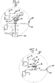
Fig. 1 ist eine Querschnittdarstellung einer Werkzeugmaschine, mit Bearbeitungsraum und Werkzeugmaschinengrundkörper und mit schwenkbarer Schutzeinrichtung. -
Fig. 2 ist eine vergrößerte Querschnittdarstellung des Ausschnitts B gemäß derFig. 1 einer ersten Ausführungsform B'. -
Fig. 3 ist eine vergrößerte Querschnittdarstellung des Ausschnitts B gemäß derFig. 1 einer zweiten Ausführungsform B". -
Figur 1 zeigt eine Querschnittdarstellung, gemäß einer Ausführungsform der Erfindung, einer Werkzeugmaschine 1, welche einen Bearbeitungsraum 2, eine Schutzeinrichtung 10 und einen Werkzeugmaschinengrundkörper 20 umfasst. - Zudem ist ein Koordinatensystem definiert, welches seinen Ursprung in der Ebene eines Maschinenbodens 21 der Werkzeugmaschine 1 hat. Dabei liegt die X-Achse orthogonal auf dem Maschinenboden 21 und verläuft nach oben, in Richtung des Bearbeitungsraumes 2. Die Y-Achse liegt in der Ebene des Maschinenbodens 21 und ist orthogonal zur X-Achse und zur Schutzeinrichtung 10. Die Y-Achse verläuft in Richtung des hinteren Teils der Werkzeugmaschine 1, das heißt sie zeigt weg von der Schutzeinrichtung 10. Die Z-Achse liegt orthogonal zur Y- und X-Achse und zeigt aus der Zeichenebene hinaus.
- Der Bearbeitungsraum 2 ist der Raum in dem die Werkstücke mithilfe des Werkzeuges der Werkzeugmaschine 1 bearbeitet werden. Dieser Bereich wird vom öffentlichen Bereich 3, in dem sich zum Beispiel die Bediener 3 befinden, durch eine Schutzeinrichtung 10 abgegrenzt. Zum Herausnehmen und Hineinlegen der Werkstücke oder zum Wechseln des Werkzeuges kann die Schutzeinrichtung 10 entfernt bzw. geöffnet werden. Eine Möglichkeit ist in
Figur 1 gezeigt und zeigt einen Klappmechanismus, mit dem eine Maschinenklappe 12 nach oben geklappt wird. Dabei ist das Gelenk am oben Ende der Werkzeugmaschine 1 angebracht, so dass die Maschinenklappe 12 um eine Z'-Achse (Rotationsachse im Gelenk und parallel zur Z-Achse) rotieren kann. In einer weiteren Ausführungsform (nicht dargestellt) kann diese Mechanik beispielsweise durch eine Schutzeinrichtung 10 mit verschiebbarer Maschinenklappe 12 ersetzt werden. Die Maschinenklappe 12 ist dann an einer linearen Führung gelagert, die sich an der Oberseite oder Unterseite der Klappe 12 befindet. Die Klappe 12 verfährt beim Öffnen oder Schließen der Schutzeinrichtung 10 parallel zur Z-Achse. - An der Maschinenklappe 12 ist gemäß der Erfindung ein verschließbares Teil 13 angebracht. Dieses Teil ist im Vergrößerungsbereich B schematisch dargestellt und wird in den nachfolgenden Darstellungen näher erläutert. Das verschließbare Teil 13 kann in verschiedenen Ausführungsformen ausgeführt werden, die im Folgenden näher beschrieben werden.
- Der Werkzeugmaschinengrundkörper 20 umfasst unter anderem den Maschinenboden 21 und einen schematisch dargestellten Riegel 22. Die verschiedenen Ausführungsformen und eine genaue Darstellung ist zwecks Übersichtlichkeit auch hier in den nachfolgenden Darstellungen und Ausführungsformen ausgeführt.
- Die Längsschnittdarstellung des Vergrößerungsbereichs B in
Figur 2 zeigt eine erste Ausführungsform B' der Erfindung. Im oberen Teil der Vergrößerung befindet sich die Schutzeinrichtung 10 mit der Maschinenklappe 12. An der Maschinenklappe befindet sich das verschließbare Teil 13 in der ersten Ausführungsform. Dieses verschließbare Teil 13 ist in diesem Fall ein gewinkeltes Blech, welches über mindestens zwei Biegungen mit 90° Winkel verfügt, so dass zwei gegenüberliegende Seiten parallel sind. Eine dieser Seiten, oder Schenkel, wird an der Maschinenklappe 12 mit mindestens einem Befestigungselement fixiert. Das gewinkelte Blech schließt gemäß der ersten Ausführungsform nach den zwei parallelen Seiten, nach unten in negativer X- Richtung ab. So entsteht ein offenes Profil bzw. eine Öffnung 14. Alternativ zu einem gewinkelten Blech kann zum Beispiel auch ein Vierkantrohr, beispielsweise aus Aluminium, verwendet werden, welches an einer Seite aufgeschnitten wird oder welches so montiert wird, dass eine Öffnung 14 in negativer X-Richtung vorhanden ist. - Das verschließbare Teil beinhaltet nach einer ersten Ausführungsform der Erfindung eine passive Spule bzw. Sensor 15. Dieser wird über ein Befestigungselement oder ein Adhäsiv am verschließbaren Teil befestigt.
- Der Maschinenboden 21 des Werkzeugmaschinengrundkörpers 20 umfasst weiterhin den Riegel 22. Dieser kann gemäß der Erfindung bodentief versenkt werden, das heißt, dass die Deckelfläche 25 des Riegels 22 in einer Ebene mit dem Maschinenboden 21 liegt und diese nicht überragt. Der Riegel 22 kann aus einem Vollmaterial oder zum Beispiel einer Kolbenstange mit Hohlbohrung bestehen. Gemäß der ersten Ausführungsform der Erfindung wird in diesen Riegel 22 eine aktive Spule bzw. Sensor 24 in der Deckelfläche 25 eingelassen. Dazu wird in den Riegel 22 eine Vertiefung oder Stufe gefräst, gebohrt, gedreht, oder bei additiven Verfahren konstruiert, in die die Spule 24 eingesetzt wird. Die Spule 24 schließt mit der Deckelfläche 25 des Riegels 22 ab und bildet so eine Einheit mit dem Riegel 22. Die aktive Spule umfasst zudem noch Kabel, welche im Riegel 22 zu einer Leistungs- und Auswertelektronik 23 geführt werden. Dort werden die Signale verarbeitet und weitergegeben.
- Der Riegel wird mit einer Einheit unterhalb des Maschinenbodens in X-Richtung verfahren. Diese Funktion kann ein mechanisches, pneumatisches, elektrisches, magnetisches oder hydraulisches System ausführen.
- Die Positionierung von verschließbaren Teil 13 und Riegel 22 muss in der Genauigkeit erfolgen, so dass die Spulen bzw. Sensoren in einer Achse parallel zueinander liegen. Ein gewisser Versatz im Raum innerhalb einer vorgegebenen Toleranz ist zwar erlaubt, sollte aber auf ein Minimum begrenzt werden. Zudem muss der Riegel 22 so positioniert sein, dass er in der Verriegelungsposition in die Öffnung 14, des verschließbaren Teils 13 eingreift.
Figur 3 zeigt eine Querschnittdarstellung des Vergrößerungsbereichs B in einer zweiten Ausführungsform B". Diese Ausführungsform unterscheidet sich im Wesentlichen dadurch, dass eine aktive Spule 15 nun im verschließbaren Teil 13 und eine passive Spule 24 in der Vertiefung des Riegels 22 sitzt. Zudem besitzt der verschließbare Teil 13 eine weitere Seite bzw. Schenkel, die zwischen den zwei parallelen Seiten des verschließbaren Teils 13 eingesetzt wird. Die Befestigung kann durch Schweißen, Kleben, Bördeln, oder durch einen Formschluss erfolgen. Dieser neue Schenkel weißt eine Öffnung 14 auf, in der der Riegel 22 eingreift und die einen größeren Umfang als den Umfang des Riegels aufweist. Die Öffnung kann durch Bohren, Fräsen oder ähnlichen hergestellt werden. Sollte das verschließbare Teil 13 beispielsweise durch ein Vierkantrohr realisiert werden, wird in eine entsprechende Seite, die parallel zum Maschinenboden 21 ist, eine Öffnung 14 geschaffen. -
- 1
- Werkzeugmaschine
- 2
- Bearbeitungsraum
- 3
- Bediener / öffentlicher Bereich
- 10
- Schutzeinrichtung
- 12
- Maschinenklappe
- 13
- verschließbares Teil
- 14
- Öffnung
- 15
- Spule
- 20
- Werkzeugmaschinengrundkörper
- 21
- Maschinenboden
- 22
- Riegel
- 23
- Leistungs- und Auswertelektronik
- 24
- Spule
- 25
- Deckelfläche des Riegels
- B
- Vergößerungsbereich
- B'
- Vergrößerungsbereich der ersten Ausführungsform
- B"
- Vergrößerungsbereich der zweiten Ausführungsform
Claims (11)
- Werkzeugmaschine (1) zur Bearbeitung von bevorzugt plattenförmigen Werkstücken, die bevorzugt zumindest abschnittsweise aus Holz, Holzwerkstoffen oder Kunststoffen bestehen, mit:einem Bearbeitungsraum (2), der nach unten in Richtung Boden durch einen Maschinenboden (21) und in Richtung des Bedieners (3) durch eine Schutzeinrichtung (10) begrenzt ist,einem Riegel (22), bevorzugt ein Zylinder, mit einer Deckelfläche (25),einem verschließbaren Teil (13), welches an der Schutzeinrichtung (10) fixiert ist,einem Verriegelungssystem der Schutzeinrichtung (10), welches den verschließbaren Teil (13) und den Riegel (22) beinhaltet,einer Leistungs- und Auswerteinheit (23), welche eingerichtet ist, um die Signale einer ersten und einer zweiten Spule (15, 24) auszulesen und zu verarbeiten,dadurch gekennzeichnet, dassdie Deckelfläche (25) des Riegels (22) bei geöffneter Schutzeinrichtung (10) mit dem Maschinenboden (21) in einer Ebene oder darunter liegt.
- Werkzeugmaschine (1) nach einem der vorherigen Ansprüche, wobei der Riegel (22) in einer zu Bodenfläche winkligen Richtung, zwischen einer Verriegelungsposition und einer Entriegelungsposition verfahrbar ist.
- Werkzeugmaschine (1) nach einem der vorherigen Ansprüche, wobei der Riegel (22) in einer Entriegelungsposition aus dem verschließbaren Teil (13) gezogen ist und in einer Verriegelungsposition in das verschließbare Teil (13) hineinragt.
- Werkzeugmaschine (1) nach einem der vorherigen Ansprüche, wobei die Schutzeinrichtung (10) eine Haube, Schutztüre, Klappe, oder ein anderes bewegliches Element darstellt
- Werkzeugmaschine (1) nach einem der vorherigen Ansprüche, wobei die erste Spule (15) eine passive oder aktive Spule ist.
- Werkzeugmaschine (1) nach einem der vorherigen Ansprüche, wobei die zweite Spule (24) eine aktive oder passive Spule ist.
- Werkzeugmaschine (1) nach einem der vorherigen Ansprüche, wobei der Riegel (22) an der Deckfläche (25) eine Stufe aufweist, in der die zweite Spule (24) eingesetzt und fixiert wird.
- Werkzeugmaschine (1) nach einem der vorherigen Ansprüche, wobei die erste Spule (15) an dem verschließbaren Teil (13) angeordnet ist, und dort bevorzugt durch ein Adhäsiv oder ein Befestigungselement fixiert ist.
- Werkzeugmaschine (1) nach einem der vorherigen Ansprüche, wobei der Riegel (22) eine durchgehende Kolbenstange und Hohlbohrung aufweist oder aus einem Vollmaterial besteht.
- Werkzeugmaschine (1) nach einem der vorherigen Ansprüche, wobei der Riegel (22) durch ein pneumatisches, mechanisches, hydraulisches, elektrisches oder magnetisches System ein- und ausgefahren wird.
Werkzeugmaschine (1) nach einem der vorherigen Ansprüche, wobei die Leistungs- und Auswerteinheit (23) derart eingerichtet ist, dass die Werkzeugmaschine (1) nur in Betrieb genommen werden kann, wenn die beiden Spulen in einer vorbestimmten der richtigen Position zueinander sind. - Werkzeugmaschine (1) nach einem der vorherigen Ansprüche, wobei die Leistungs- und Auswerteinheit (23) derart eingerichtet ist, dass die Werkzeugmaschine (1) nur in Betrieb genommen werden kann, wenn eine Codierung der ersten und zweiten Spule (15, 24) übereinstimmt.
Applications Claiming Priority (1)
| Application Number | Priority Date | Filing Date | Title |
|---|---|---|---|
| DE102015209923.7A DE102015209923A1 (de) | 2015-05-29 | 2015-05-29 | Werkzeugmaschine |
Publications (2)
| Publication Number | Publication Date |
|---|---|
| EP3101328A1 true EP3101328A1 (de) | 2016-12-07 |
| EP3101328B1 EP3101328B1 (de) | 2020-01-15 |
Family
ID=56081265
Family Applications (1)
| Application Number | Title | Priority Date | Filing Date |
|---|---|---|---|
| EP16170588.4A Active EP3101328B1 (de) | 2015-05-29 | 2016-05-20 | Werkzeugmaschine |
Country Status (3)
| Country | Link |
|---|---|
| EP (1) | EP3101328B1 (de) |
| DE (1) | DE102015209923A1 (de) |
| ES (1) | ES2772275T3 (de) |
Cited By (1)
| Publication number | Priority date | Publication date | Assignee | Title |
|---|---|---|---|---|
| CN108907733A (zh) * | 2018-07-13 | 2018-11-30 | 苏州市启献智能科技有限公司 | 一种五金件智能冲压铣床及其系统 |
Families Citing this family (2)
| Publication number | Priority date | Publication date | Assignee | Title |
|---|---|---|---|---|
| DE102017206781A1 (de) * | 2017-04-21 | 2018-10-25 | Festo Ag & Co. Kg | Verriegelungseinrichtung und Verriegelungssystem |
| CN112123007B (zh) * | 2020-11-25 | 2021-02-19 | 北京中航科电测控技术股份有限公司 | 一种具有防护组件的零件加工自动化生产线 |
Citations (10)
| Publication number | Priority date | Publication date | Assignee | Title |
|---|---|---|---|---|
| GB906862A (en) * | 1957-12-31 | 1962-09-26 | Gregory Wilson Parkes | Improvements in or relating to machinery safety devices |
| DE3606458A1 (de) * | 1986-02-27 | 1987-09-03 | Siemens Ag | Elektromechanische verriegelungsanordnung |
| EP1136745A2 (de) * | 2000-03-22 | 2001-09-26 | Eppendorf Ag | Verriegelung eines Verschlusses mit einem Gehäuse |
| DE10252025A1 (de) * | 2002-11-06 | 2004-05-27 | Klaschka Gmbh & Co | Schloß |
| DE102006046437A1 (de) * | 2006-09-25 | 2008-04-10 | Euchner Gmbh + Co. Kg | Vorrichtung zum Überwachen des Zustandes einer sicherheitsrelevanten Einrichtung |
| EP2295679A2 (de) * | 2009-09-14 | 2011-03-16 | K.A. Schmersal Holding GmbH & Co. KG | Zuhaltung für ein Bauteil zum Verschließen einer Öffnung |
| JP2011143483A (ja) * | 2010-01-12 | 2011-07-28 | Disco Abrasive Syst Ltd | 加工装置カバーの開閉扉構造 |
| DE202012001077U1 (de) * | 2012-02-03 | 2012-03-02 | Sigma Laborzentrifugen Gmbh | Deckelschloss |
| DE102012106719A1 (de) | 2012-07-24 | 2014-01-30 | K.A. Schmersal Holding Gmbh & Co. Kg | Zugangsschutzvorrichtung und ein Verfahren zum Überwachen eines Zustandes der Zugangsschutzvorrichtung |
| WO2014079959A1 (de) | 2012-11-23 | 2014-05-30 | Pilz Gmbh & Co. Kg | Schutztürüberwachungssystem |
-
2015
- 2015-05-29 DE DE102015209923.7A patent/DE102015209923A1/de not_active Withdrawn
-
2016
- 2016-05-20 ES ES16170588T patent/ES2772275T3/es active Active
- 2016-05-20 EP EP16170588.4A patent/EP3101328B1/de active Active
Patent Citations (10)
| Publication number | Priority date | Publication date | Assignee | Title |
|---|---|---|---|---|
| GB906862A (en) * | 1957-12-31 | 1962-09-26 | Gregory Wilson Parkes | Improvements in or relating to machinery safety devices |
| DE3606458A1 (de) * | 1986-02-27 | 1987-09-03 | Siemens Ag | Elektromechanische verriegelungsanordnung |
| EP1136745A2 (de) * | 2000-03-22 | 2001-09-26 | Eppendorf Ag | Verriegelung eines Verschlusses mit einem Gehäuse |
| DE10252025A1 (de) * | 2002-11-06 | 2004-05-27 | Klaschka Gmbh & Co | Schloß |
| DE102006046437A1 (de) * | 2006-09-25 | 2008-04-10 | Euchner Gmbh + Co. Kg | Vorrichtung zum Überwachen des Zustandes einer sicherheitsrelevanten Einrichtung |
| EP2295679A2 (de) * | 2009-09-14 | 2011-03-16 | K.A. Schmersal Holding GmbH & Co. KG | Zuhaltung für ein Bauteil zum Verschließen einer Öffnung |
| JP2011143483A (ja) * | 2010-01-12 | 2011-07-28 | Disco Abrasive Syst Ltd | 加工装置カバーの開閉扉構造 |
| DE202012001077U1 (de) * | 2012-02-03 | 2012-03-02 | Sigma Laborzentrifugen Gmbh | Deckelschloss |
| DE102012106719A1 (de) | 2012-07-24 | 2014-01-30 | K.A. Schmersal Holding Gmbh & Co. Kg | Zugangsschutzvorrichtung und ein Verfahren zum Überwachen eines Zustandes der Zugangsschutzvorrichtung |
| WO2014079959A1 (de) | 2012-11-23 | 2014-05-30 | Pilz Gmbh & Co. Kg | Schutztürüberwachungssystem |
Cited By (1)
| Publication number | Priority date | Publication date | Assignee | Title |
|---|---|---|---|---|
| CN108907733A (zh) * | 2018-07-13 | 2018-11-30 | 苏州市启献智能科技有限公司 | 一种五金件智能冲压铣床及其系统 |
Also Published As
| Publication number | Publication date |
|---|---|
| DE102015209923A1 (de) | 2016-12-01 |
| EP3101328B1 (de) | 2020-01-15 |
| ES2772275T3 (es) | 2020-07-07 |
Similar Documents
| Publication | Publication Date | Title |
|---|---|---|
| DE19830903B4 (de) | Einrichtung sowie Verfahren zur Bearbeitung von Bohrungen in einem Werkstück unter Verwendung einer solchen Einrichtung | |
| DE102017205533B4 (de) | Haltevorrichtung, Kraftfahrzeug | |
| EP3622149B1 (de) | Schiene zur führung eines schlittens einer möbeltüre | |
| DE202015004517U1 (de) | Werkzeugmaschine | |
| EP3101328B1 (de) | Werkzeugmaschine | |
| AT511231B1 (de) | Schutzabdeckung für eine spritzgiessmaschine | |
| DE202012003004U1 (de) | Vorrichtung zum Bewegen eines ersten Möbelteils relativ zu einem zweiten Möbelteil | |
| EP1574776B1 (de) | Schutzeinrichtung, insbesondere Lichtgitter | |
| EP0205985A1 (de) | Vorrichtung zur Sicherheitsabschaltung für maschinell bewegte Werkzeuge, insbesondere automatische Schweisspistolen | |
| EP1840448A1 (de) | Variable Schutzkabine | |
| EP1259340A1 (de) | Sicherheitseinrichtung für eine fertigungsmaschine, z.b. eine abkantpresse | |
| EP0639120B1 (de) | Werkzeugmaschine | |
| EP3498960B1 (de) | Verriegelungsvorrichtung für eine tür, insbesondere schiebetür | |
| EP3128528A1 (de) | Modulanordnung | |
| DE102018009165A1 (de) | Hydraulisch betätigbare Spannvorrichtung mit einem Blockteil, einem Kolben und einem Spannteil und Verfahren zum Betätigen der Spannvorrichtung | |
| EP4361491B1 (de) | Schutztürüberwachungsmodul | |
| EP2857153B1 (de) | Ausgleichseinheit und Ausgleichssystem | |
| DE102015101852B3 (de) | Schutzeinrichtung für eine Spritzgießmaschine | |
| EP0728650A1 (de) | Verschiebeeinrichtung zum horizontalen Verschieben schwerer Lasten | |
| DE202016106504U1 (de) | Montagewerkzeug für die Montage einer Schaltschranktür an einem Schaltschrankgehäuse und eine entsprechende Schaltschrankanordnung | |
| DE4136584B4 (de) | Bohr- und Meisselgerät mit Werkzeugaufnahme | |
| DE102007020313B4 (de) | Vorrichtung zum Überwachen des Zustandes einer Schutzeinrichtung einer Maschine | |
| DE102015114596B4 (de) | Werkzeugschrank | |
| WO2016189085A1 (de) | Abdeckeinrichtung für eine werkzeugablagestation | |
| WO1991017333A1 (de) | Mit schlosseinrichtung versehener versenkbarer schwenkhebelverschluss |
Legal Events
| Date | Code | Title | Description |
|---|---|---|---|
| PUAI | Public reference made under article 153(3) epc to a published international application that has entered the european phase |
Free format text: ORIGINAL CODE: 0009012 |
|
| STAA | Information on the status of an ep patent application or granted ep patent |
Free format text: STATUS: THE APPLICATION HAS BEEN PUBLISHED |
|
| AK | Designated contracting states |
Kind code of ref document: A1 Designated state(s): AL AT BE BG CH CY CZ DE DK EE ES FI FR GB GR HR HU IE IS IT LI LT LU LV MC MK MT NL NO PL PT RO RS SE SI SK SM TR |
|
| AX | Request for extension of the european patent |
Extension state: BA ME |
|
| STAA | Information on the status of an ep patent application or granted ep patent |
Free format text: STATUS: REQUEST FOR EXAMINATION WAS MADE |
|
| 17P | Request for examination filed |
Effective date: 20170116 |
|
| RBV | Designated contracting states (corrected) |
Designated state(s): AL AT BE BG CH CY CZ DE DK EE ES FI FR GB GR HR HU IE IS IT LI LT LU LV MC MK MT NL NO PL PT RO RS SE SI SK SM TR |
|
| STAA | Information on the status of an ep patent application or granted ep patent |
Free format text: STATUS: EXAMINATION IS IN PROGRESS |
|
| 17Q | First examination report despatched |
Effective date: 20190110 |
|
| GRAP | Despatch of communication of intention to grant a patent |
Free format text: ORIGINAL CODE: EPIDOSNIGR1 |
|
| STAA | Information on the status of an ep patent application or granted ep patent |
Free format text: STATUS: GRANT OF PATENT IS INTENDED |
|
| INTG | Intention to grant announced |
Effective date: 20190716 |
|
| GRAS | Grant fee paid |
Free format text: ORIGINAL CODE: EPIDOSNIGR3 |
|
| GRAJ | Information related to disapproval of communication of intention to grant by the applicant or resumption of examination proceedings by the epo deleted |
Free format text: ORIGINAL CODE: EPIDOSDIGR1 |
|
| GRAL | Information related to payment of fee for publishing/printing deleted |
Free format text: ORIGINAL CODE: EPIDOSDIGR3 |
|
| STAA | Information on the status of an ep patent application or granted ep patent |
Free format text: STATUS: EXAMINATION IS IN PROGRESS |
|
| GRAR | Information related to intention to grant a patent recorded |
Free format text: ORIGINAL CODE: EPIDOSNIGR71 |
|
| STAA | Information on the status of an ep patent application or granted ep patent |
Free format text: STATUS: GRANT OF PATENT IS INTENDED |
|
| GRAA | (expected) grant |
Free format text: ORIGINAL CODE: 0009210 |
|
| STAA | Information on the status of an ep patent application or granted ep patent |
Free format text: STATUS: THE PATENT HAS BEEN GRANTED |
|
| INTC | Intention to grant announced (deleted) | ||
| AK | Designated contracting states |
Kind code of ref document: B1 Designated state(s): AL AT BE BG CH CY CZ DE DK EE ES FI FR GB GR HR HU IE IS IT LI LT LU LV MC MK MT NL NO PL PT RO RS SE SI SK SM TR |
|
| INTG | Intention to grant announced |
Effective date: 20191209 |
|
| REG | Reference to a national code |
Ref country code: CH Ref legal event code: EP Ref country code: GB Ref legal event code: FG4D Free format text: NOT ENGLISH |
|
| REG | Reference to a national code |
Ref country code: IE Ref legal event code: FG4D Free format text: LANGUAGE OF EP DOCUMENT: GERMAN |
|
| REG | Reference to a national code |
Ref country code: DE Ref legal event code: R096 Ref document number: 502016008407 Country of ref document: DE |
|
| REG | Reference to a national code |
Ref country code: AT Ref legal event code: REF Ref document number: 1225457 Country of ref document: AT Kind code of ref document: T Effective date: 20200215 |
|
| REG | Reference to a national code |
Ref country code: NL Ref legal event code: MP Effective date: 20200115 |
|
| REG | Reference to a national code |
Ref country code: ES Ref legal event code: FG2A Ref document number: 2772275 Country of ref document: ES Kind code of ref document: T3 Effective date: 20200707 |
|
| REG | Reference to a national code |
Ref country code: LT Ref legal event code: MG4D |
|
| PG25 | Lapsed in a contracting state [announced via postgrant information from national office to epo] |
Ref country code: FI Free format text: LAPSE BECAUSE OF FAILURE TO SUBMIT A TRANSLATION OF THE DESCRIPTION OR TO PAY THE FEE WITHIN THE PRESCRIBED TIME-LIMIT Effective date: 20200115 Ref country code: NO Free format text: LAPSE BECAUSE OF FAILURE TO SUBMIT A TRANSLATION OF THE DESCRIPTION OR TO PAY THE FEE WITHIN THE PRESCRIBED TIME-LIMIT Effective date: 20200415 Ref country code: RS Free format text: LAPSE BECAUSE OF FAILURE TO SUBMIT A TRANSLATION OF THE DESCRIPTION OR TO PAY THE FEE WITHIN THE PRESCRIBED TIME-LIMIT Effective date: 20200115 Ref country code: NL Free format text: LAPSE BECAUSE OF FAILURE TO SUBMIT A TRANSLATION OF THE DESCRIPTION OR TO PAY THE FEE WITHIN THE PRESCRIBED TIME-LIMIT Effective date: 20200115 Ref country code: PT Free format text: LAPSE BECAUSE OF FAILURE TO SUBMIT A TRANSLATION OF THE DESCRIPTION OR TO PAY THE FEE WITHIN THE PRESCRIBED TIME-LIMIT Effective date: 20200607 |
|
| PG25 | Lapsed in a contracting state [announced via postgrant information from national office to epo] |
Ref country code: BG Free format text: LAPSE BECAUSE OF FAILURE TO SUBMIT A TRANSLATION OF THE DESCRIPTION OR TO PAY THE FEE WITHIN THE PRESCRIBED TIME-LIMIT Effective date: 20200415 Ref country code: IS Free format text: LAPSE BECAUSE OF FAILURE TO SUBMIT A TRANSLATION OF THE DESCRIPTION OR TO PAY THE FEE WITHIN THE PRESCRIBED TIME-LIMIT Effective date: 20200515 Ref country code: GR Free format text: LAPSE BECAUSE OF FAILURE TO SUBMIT A TRANSLATION OF THE DESCRIPTION OR TO PAY THE FEE WITHIN THE PRESCRIBED TIME-LIMIT Effective date: 20200416 Ref country code: HR Free format text: LAPSE BECAUSE OF FAILURE TO SUBMIT A TRANSLATION OF THE DESCRIPTION OR TO PAY THE FEE WITHIN THE PRESCRIBED TIME-LIMIT Effective date: 20200115 Ref country code: SE Free format text: LAPSE BECAUSE OF FAILURE TO SUBMIT A TRANSLATION OF THE DESCRIPTION OR TO PAY THE FEE WITHIN THE PRESCRIBED TIME-LIMIT Effective date: 20200115 Ref country code: LV Free format text: LAPSE BECAUSE OF FAILURE TO SUBMIT A TRANSLATION OF THE DESCRIPTION OR TO PAY THE FEE WITHIN THE PRESCRIBED TIME-LIMIT Effective date: 20200115 |
|
| REG | Reference to a national code |
Ref country code: DE Ref legal event code: R097 Ref document number: 502016008407 Country of ref document: DE |
|
| PG25 | Lapsed in a contracting state [announced via postgrant information from national office to epo] |
Ref country code: CZ Free format text: LAPSE BECAUSE OF FAILURE TO SUBMIT A TRANSLATION OF THE DESCRIPTION OR TO PAY THE FEE WITHIN THE PRESCRIBED TIME-LIMIT Effective date: 20200115 Ref country code: RO Free format text: LAPSE BECAUSE OF FAILURE TO SUBMIT A TRANSLATION OF THE DESCRIPTION OR TO PAY THE FEE WITHIN THE PRESCRIBED TIME-LIMIT Effective date: 20200115 Ref country code: LT Free format text: LAPSE BECAUSE OF FAILURE TO SUBMIT A TRANSLATION OF THE DESCRIPTION OR TO PAY THE FEE WITHIN THE PRESCRIBED TIME-LIMIT Effective date: 20200115 Ref country code: SK Free format text: LAPSE BECAUSE OF FAILURE TO SUBMIT A TRANSLATION OF THE DESCRIPTION OR TO PAY THE FEE WITHIN THE PRESCRIBED TIME-LIMIT Effective date: 20200115 Ref country code: SM Free format text: LAPSE BECAUSE OF FAILURE TO SUBMIT A TRANSLATION OF THE DESCRIPTION OR TO PAY THE FEE WITHIN THE PRESCRIBED TIME-LIMIT Effective date: 20200115 Ref country code: EE Free format text: LAPSE BECAUSE OF FAILURE TO SUBMIT A TRANSLATION OF THE DESCRIPTION OR TO PAY THE FEE WITHIN THE PRESCRIBED TIME-LIMIT Effective date: 20200115 Ref country code: DK Free format text: LAPSE BECAUSE OF FAILURE TO SUBMIT A TRANSLATION OF THE DESCRIPTION OR TO PAY THE FEE WITHIN THE PRESCRIBED TIME-LIMIT Effective date: 20200115 |
|
| PLBE | No opposition filed within time limit |
Free format text: ORIGINAL CODE: 0009261 |
|
| STAA | Information on the status of an ep patent application or granted ep patent |
Free format text: STATUS: NO OPPOSITION FILED WITHIN TIME LIMIT |
|
| 26N | No opposition filed |
Effective date: 20201016 |
|
| PG25 | Lapsed in a contracting state [announced via postgrant information from national office to epo] |
Ref country code: LI Free format text: LAPSE BECAUSE OF NON-PAYMENT OF DUE FEES Effective date: 20200531 Ref country code: MC Free format text: LAPSE BECAUSE OF FAILURE TO SUBMIT A TRANSLATION OF THE DESCRIPTION OR TO PAY THE FEE WITHIN THE PRESCRIBED TIME-LIMIT Effective date: 20200115 Ref country code: CH Free format text: LAPSE BECAUSE OF NON-PAYMENT OF DUE FEES Effective date: 20200531 |
|
| PG25 | Lapsed in a contracting state [announced via postgrant information from national office to epo] |
Ref country code: SI Free format text: LAPSE BECAUSE OF FAILURE TO SUBMIT A TRANSLATION OF THE DESCRIPTION OR TO PAY THE FEE WITHIN THE PRESCRIBED TIME-LIMIT Effective date: 20200115 Ref country code: PL Free format text: LAPSE BECAUSE OF FAILURE TO SUBMIT A TRANSLATION OF THE DESCRIPTION OR TO PAY THE FEE WITHIN THE PRESCRIBED TIME-LIMIT Effective date: 20200115 |
|
| REG | Reference to a national code |
Ref country code: BE Ref legal event code: MM Effective date: 20200531 |
|
| GBPC | Gb: european patent ceased through non-payment of renewal fee |
Effective date: 20200520 |
|
| PG25 | Lapsed in a contracting state [announced via postgrant information from national office to epo] |
Ref country code: LU Free format text: LAPSE BECAUSE OF NON-PAYMENT OF DUE FEES Effective date: 20200520 |
|
| PG25 | Lapsed in a contracting state [announced via postgrant information from national office to epo] |
Ref country code: GB Free format text: LAPSE BECAUSE OF NON-PAYMENT OF DUE FEES Effective date: 20200520 Ref country code: IE Free format text: LAPSE BECAUSE OF NON-PAYMENT OF DUE FEES Effective date: 20200520 Ref country code: FR Free format text: LAPSE BECAUSE OF NON-PAYMENT OF DUE FEES Effective date: 20200531 |
|
| PG25 | Lapsed in a contracting state [announced via postgrant information from national office to epo] |
Ref country code: BE Free format text: LAPSE BECAUSE OF NON-PAYMENT OF DUE FEES Effective date: 20200531 |
|
| PG25 | Lapsed in a contracting state [announced via postgrant information from national office to epo] |
Ref country code: TR Free format text: LAPSE BECAUSE OF FAILURE TO SUBMIT A TRANSLATION OF THE DESCRIPTION OR TO PAY THE FEE WITHIN THE PRESCRIBED TIME-LIMIT Effective date: 20200115 Ref country code: MT Free format text: LAPSE BECAUSE OF FAILURE TO SUBMIT A TRANSLATION OF THE DESCRIPTION OR TO PAY THE FEE WITHIN THE PRESCRIBED TIME-LIMIT Effective date: 20200115 Ref country code: CY Free format text: LAPSE BECAUSE OF FAILURE TO SUBMIT A TRANSLATION OF THE DESCRIPTION OR TO PAY THE FEE WITHIN THE PRESCRIBED TIME-LIMIT Effective date: 20200115 |
|
| PG25 | Lapsed in a contracting state [announced via postgrant information from national office to epo] |
Ref country code: MK Free format text: LAPSE BECAUSE OF FAILURE TO SUBMIT A TRANSLATION OF THE DESCRIPTION OR TO PAY THE FEE WITHIN THE PRESCRIBED TIME-LIMIT Effective date: 20200115 Ref country code: AL Free format text: LAPSE BECAUSE OF FAILURE TO SUBMIT A TRANSLATION OF THE DESCRIPTION OR TO PAY THE FEE WITHIN THE PRESCRIBED TIME-LIMIT Effective date: 20200115 |
|
| P01 | Opt-out of the competence of the unified patent court (upc) registered |
Effective date: 20230529 |
|
| PGFP | Annual fee paid to national office [announced via postgrant information from national office to epo] |
Ref country code: DE Payment date: 20250520 Year of fee payment: 10 |
|
| PGFP | Annual fee paid to national office [announced via postgrant information from national office to epo] |
Ref country code: ES Payment date: 20250603 Year of fee payment: 10 |
|
| PGFP | Annual fee paid to national office [announced via postgrant information from national office to epo] |
Ref country code: IT Payment date: 20250522 Year of fee payment: 10 |
|
| PGFP | Annual fee paid to national office [announced via postgrant information from national office to epo] |
Ref country code: AT Payment date: 20250520 Year of fee payment: 10 |