EP3100789A1 - Pistolet automatique de pulvérisation de fluide - Google Patents
Pistolet automatique de pulvérisation de fluide Download PDFInfo
- Publication number
- EP3100789A1 EP3100789A1 EP15170861.7A EP15170861A EP3100789A1 EP 3100789 A1 EP3100789 A1 EP 3100789A1 EP 15170861 A EP15170861 A EP 15170861A EP 3100789 A1 EP3100789 A1 EP 3100789A1
- Authority
- EP
- European Patent Office
- Prior art keywords
- spray gun
- chamber
- adapter
- automatic spray
- piston
- Prior art date
- Legal status (The legal status is an assumption and is not a legal conclusion. Google has not performed a legal analysis and makes no representation as to the accuracy of the status listed.)
- Granted
Links
- 239000012530 fluid Substances 0.000 title claims abstract description 51
- 238000005507 spraying Methods 0.000 title claims abstract description 10
- 238000002347 injection Methods 0.000 title description 5
- 239000007924 injection Substances 0.000 title description 5
- 239000007921 spray Substances 0.000 claims abstract description 151
- 239000006199 nebulizer Substances 0.000 claims 1
- 239000003570 air Substances 0.000 description 127
- 239000000463 material Substances 0.000 description 18
- 239000003795 chemical substances by application Substances 0.000 description 5
- 230000006835 compression Effects 0.000 description 5
- 238000007906 compression Methods 0.000 description 5
- 241000894006 Bacteria Species 0.000 description 4
- 230000033228 biological regulation Effects 0.000 description 4
- 238000012423 maintenance Methods 0.000 description 4
- 238000012856 packing Methods 0.000 description 4
- 238000004140 cleaning Methods 0.000 description 3
- 230000007423 decrease Effects 0.000 description 3
- 238000011161 development Methods 0.000 description 3
- 230000018109 developmental process Effects 0.000 description 3
- 210000003746 feather Anatomy 0.000 description 3
- 235000013305 food Nutrition 0.000 description 3
- 235000013361 beverage Nutrition 0.000 description 2
- 230000003993 interaction Effects 0.000 description 2
- 239000011344 liquid material Substances 0.000 description 2
- 238000004519 manufacturing process Methods 0.000 description 2
- 239000002245 particle Substances 0.000 description 2
- 230000001007 puffing effect Effects 0.000 description 2
- 230000003584 silencer Effects 0.000 description 2
- 239000000243 solution Substances 0.000 description 2
- 239000004063 acid-resistant material Substances 0.000 description 1
- 239000012080 ambient air Substances 0.000 description 1
- 235000015173 baked goods and baking mixes Nutrition 0.000 description 1
- 238000006243 chemical reaction Methods 0.000 description 1
- 235000019219 chocolate Nutrition 0.000 description 1
- 238000000576 coating method Methods 0.000 description 1
- 238000011109 contamination Methods 0.000 description 1
- 239000002537 cosmetic Substances 0.000 description 1
- 230000001419 dependent effect Effects 0.000 description 1
- 210000004907 gland Anatomy 0.000 description 1
- 239000012535 impurity Substances 0.000 description 1
- 239000002184 metal Substances 0.000 description 1
- 230000000813 microbial effect Effects 0.000 description 1
- 238000012986 modification Methods 0.000 description 1
- 230000004048 modification Effects 0.000 description 1
- 238000011022 operating instruction Methods 0.000 description 1
- 230000003287 optical effect Effects 0.000 description 1
- 239000003566 sealing material Substances 0.000 description 1
- 238000011144 upstream manufacturing Methods 0.000 description 1
Images


Classifications
-
- B—PERFORMING OPERATIONS; TRANSPORTING
- B05—SPRAYING OR ATOMISING IN GENERAL; APPLYING FLUENT MATERIALS TO SURFACES, IN GENERAL
- B05B—SPRAYING APPARATUS; ATOMISING APPARATUS; NOZZLES
- B05B15/00—Details of spraying plant or spraying apparatus not otherwise provided for; Accessories
- B05B15/60—Arrangements for mounting, supporting or holding spraying apparatus
- B05B15/65—Mounting arrangements for fluid connection of the spraying apparatus or its outlets to flow conduits
-
- B—PERFORMING OPERATIONS; TRANSPORTING
- B05—SPRAYING OR ATOMISING IN GENERAL; APPLYING FLUENT MATERIALS TO SURFACES, IN GENERAL
- B05B—SPRAYING APPARATUS; ATOMISING APPARATUS; NOZZLES
- B05B7/00—Spraying apparatus for discharge of liquids or other fluent materials from two or more sources, e.g. of liquid and air, of powder and gas
- B05B7/0081—Apparatus supplied with low pressure gas, e.g. "hvlp"-guns; air supplied by a fan
-
- B—PERFORMING OPERATIONS; TRANSPORTING
- B05—SPRAYING OR ATOMISING IN GENERAL; APPLYING FLUENT MATERIALS TO SURFACES, IN GENERAL
- B05B—SPRAYING APPARATUS; ATOMISING APPARATUS; NOZZLES
- B05B7/00—Spraying apparatus for discharge of liquids or other fluent materials from two or more sources, e.g. of liquid and air, of powder and gas
- B05B7/02—Spray pistols; Apparatus for discharge
- B05B7/12—Spray pistols; Apparatus for discharge designed to control volume of flow, e.g. with adjustable passages
- B05B7/1254—Spray pistols; Apparatus for discharge designed to control volume of flow, e.g. with adjustable passages the controlling means being fluid actuated
- B05B7/1263—Spray pistols; Apparatus for discharge designed to control volume of flow, e.g. with adjustable passages the controlling means being fluid actuated pneumatically actuated
-
- B—PERFORMING OPERATIONS; TRANSPORTING
- B05—SPRAYING OR ATOMISING IN GENERAL; APPLYING FLUENT MATERIALS TO SURFACES, IN GENERAL
- B05B—SPRAYING APPARATUS; ATOMISING APPARATUS; NOZZLES
- B05B7/00—Spraying apparatus for discharge of liquids or other fluent materials from two or more sources, e.g. of liquid and air, of powder and gas
- B05B7/24—Spraying apparatus for discharge of liquids or other fluent materials from two or more sources, e.g. of liquid and air, of powder and gas with means, e.g. a container, for supplying liquid or other fluent material to a discharge device
- B05B7/2486—Spraying apparatus for discharge of liquids or other fluent materials from two or more sources, e.g. of liquid and air, of powder and gas with means, e.g. a container, for supplying liquid or other fluent material to a discharge device with means for supplying liquid or other fluent material to several discharge devices
Definitions
- the invention relates to an automatic spray gun for spraying a fluid, which is used for example in the food, beverage, cosmetics and pharmaceutical industries.
- a fluid which is used for example in the food, beverage, cosmetics and pharmaceutical industries.
- the fluid to be sprayed also referred to as material, may be, for example, baking release agents.
- the device for applying coatings of liquid material is given.
- the liquid material is called chocolate.
- the device comprises a drive piston for a valve needle and a spring chamber, in which a return spring for the drive piston is arranged.
- the spring chamber is hermetically sealed.
- This part of the device is thus hermetically sealed, so that neither bacteria nor dirt particles can get into the spring chamber or out of the spring chamber.
- This part of the spray gun probably complies with the appropriate hygiene regulations.
- the external thread for adjusting the valve lift is problematic. Here bacteria can accumulate in the threads and multiply.
- the drive piston If, during operation, the drive piston is pressed out of the rest position against the return spring and thereby reduces the volume of the spring chamber, the air can not escape. It builds up a dynamic pressure in the spring chamber, which counteracts the movement of the drive piston, so that the drive piston now has to work against both the return spring and against the back pressure. In order to ensure functionality, the control air pressure acting on the drive piston must be increased, which means an increased expenditure of energy.
- the lowest possible losses in the material to be sprayed are desirable. If, for example, fast succession, small baking molds to be coated with release agent, it is advantageous to spray only the baking molds with release agent and in the time in which there is no baking pan in the spray area of the spray gun, no release agent to spray. This can be achieved inter alia by short spray pulses. The fastest possible opening and closing times of the spray gun are advantageous here. If now by the increased dynamic pressure in the spring chamber the Extend switching times of the spray gun, this is counterproductive in terms of material loss.
- the spring chamber can be connected via an air duct with the ambient air.
- the sprayer includes a gun barrel mounted on an adapter plate. The opening for the air flow from or into the spring chamber, which is located in the gun barrel, could be located in the adapter plate and be provided with a silencer.
- the volume in the spring chamber becomes smaller so that the air located there from the spring chamber escapes via the silencer to the environment.
- the drive piston is moved back to the rest position, the volume in the spring chamber becomes larger, so that air is sucked through the muffler into the spring chamber. If the drive piston is repeatedly moved back and forth, air is repeatedly pressed out of the spring chamber and sucked back into the spring chamber. The resulting air flow is referred to as Schnuffle air flow.
- An object of the invention is to provide an automatic spray gun for spraying a fluid, which corresponds to particularly high hygiene regulations. These may concern the puffing air and / or the leakage fluid.
- the automatic spray gun can be easily and quickly disassembled for maintenance.
- the automatic spray gun for spraying a fluid is also easy and quick to clean.
- the gun barrel of the automatic spray gun can be easily and quickly removed for maintenance.
- the inventive automatic spray gun for spraying a fluid comprises a pneumatically operated drive piston for driving a valve needle and a piston chamber for compressed air for driving the drive piston.
- a spring chamber in which a return spring for the drive piston is arranged, and a leakage chamber for leakage fluid are provided.
- the piston chamber, the leakage chamber and the spring chamber are arranged.
- an adapter is provided which is releasably secured to the gun body. An interface with channels between the gun body and adapter, the piston chamber, the spring chamber and the leakage chamber are connected to the adapter provided connections.
- the adapter has an air connection, via which air can be brought into and out of the leakage chamber and / or via the leakage fluid from the leakage chamber.
- the adapter has a piston compressed air connection, which is connected to the piston chamber via a compressed air channel.
- the adapter has an atomizer compressed-air connection, which is connected via a compressed-air channel to an atomizing air opening at the mouth of the spray gun.
- the adapter has a fluid connection, which is connected to a nozzle via a fluid channel.
- the adapter has a receptacle with which the spray gun can be fastened to a holder.
- the adapter is clamped or screwed to the bracket.
- an air channel is provided which connects the leakage chamber with the spring chamber.
- the air channel connecting the spring chamber and the leakage chamber comprises the space between the valve needle and the drive piston.
- the air channel connecting the spring chamber and the leakage chamber passes through the gun body.
- the air passage connecting the spring chamber and the leakage chamber may pass through the adapter.
- a surface is provided on the gun body, which forms the interface between the gun body and adapter.
- this surface is flat.
- it can also be stepped, for example, or also contain a recess for one or more seals.
- the interface may be provided for the piston compressed air. Additionally or alternatively, the interface for the atomizer compressed air may be provided. Additionally or alternatively, the interface may be provided for the air duct which carries the breather air leads. Additionally or alternatively, the interface may be provided for the fluid to be sprayed.
- this can be further improved by providing a device for adjusting the valve lift in the automatic spray gun.
- the device for adjusting the valve lift can have a rotatable cap, by way of which the valve lift can be set. Between the cap and the gun body, a seal is provided.
- the ratio of piston area to the cross-sectional area of the gun body in the region of the drive piston is between 0.7 and 0.95. With such an area ratio, the spray gun comes out with a minimum cross-sectional area. But even an area ratio between 0.5 and 0.7 is still quite an advantage.
- the drive which has the drive piston and the piston compressed air chamber, can be designed as a single-acting drive.
- the piston compressed air thus acts on the piston only during the stroke movement of the piston, but not during its return movement.
- the drive can also be designed as a double-acting drive.
- a compressed air connection is provided for the spring chamber.
- the spring chamber is pressurized with compressed air via the air connection. So that the compressed air does not escape from the spring chamber into the leakage chamber, the leakage chamber is separated from the spring chamber and has a separate air connection for the puffing air or the leakage fluid.
- the drive piston has an axial bore, within which the valve needle is arranged.
- a spray device which has a plurality of the automatic spray guns described above.
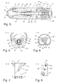
- FIG. 1 a first possible embodiment of the inventive automatic spray gun 1 for spraying a fluid M is shown in the side view.
- Figure 2 shows the first embodiment of the automatic spray gun 1 in plan view.
- the automatic spray gun 1, which is referred to below as a spray gun or as a spray gun, comprises a gun barrel 4 and an adapter 6.
- the gun barrel 4 preferably has a substantially cylindrical shape with a longitudinal axis LA. Such or similar round shape facilitates cleaning.
- the gun barrel 4 comprises a nozzle 13, an air head 2, a cap nut 3, a front body 14, a rear body 15 and at the rear end a cap 5.
- the front body 14 and the rear body 15 form the gun body.
- the union nut 3 can be screwed onto the front body 14, wherein the union nut 3 serves to fix the air head 2. So that the union nut 3 is better accessible, it can be knurled on the outside or profiled otherwise.
- the nozzle 13 is in the front body 14 screwed in and with a valve needle 32 (see Fig. 3 ) lockable. However, the nozzle 13 can also be connected to the front body 14 in another way.
- the cap 5 In the rear region of the gun barrel 4 is the cap 5, by means of which the stroke of the valve needle 32 is adjustable.
- the gun body 14, 15 is detachably connected to the adapter 6 via one or more screws 11.
- the adapter 6 is a compressed air connection 7, via which the spray gun 1 can be supplied with compressed air KL for a drive piston.
- the compressed air KL is also referred to as piston compressed air.
- a connection 8 for sniffing air SL and a connection 9 for atomizing air ZL are located on the adapter 6.
- a connection 10 for the fluid M to be sprayed can be provided on the adapter 6.
- the fluid M is also referred to below as a spray material or in short as a material.
- the adapter 6 may also have a receptacle 12.
- the entire spray gun 1 can be attached to a bracket.
- the bracket can be used as a rod 70, as in Fig. 13 shown to be trained.
- the adapter 6 can also be designed so that it can be screwed directly to a holder.
- FIG. 3 the first embodiment of the automatic spray gun 1 is shown in a first cross section along the section line CC.
- FIG. 4 shows the first embodiment of the inventive automatic spray gun 1 in cross section along the section line DD.
- FIG. 5 the automatic spray gun 1 is shown in cross section from above along the section line G - G.
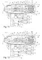
- FIG. 10 shows in the first embodiment the inventive automatic spray gun 1, the middle and rear of the barrel 4 and the adapter 6 in cross section. In the following, the spray gun 1 will be further explained in particular with reference to these figures.
- the gun barrel 4 is a single-acting pneumatic drive over which also located in the gun barrel 4 valve needle 32 can be moved.
- the compressed air drive or drive briefly comprises a drive piston 37 and a piston chamber 36 which can be acted upon with compressed air KL.
- the piston chamber 36 is formed by the rear body 15 and the drive piston 37.
- a seal 25 By means of a seal 25, the piston chamber is sealed to the front and by means of a seal 31 to the rear.
- the seal 25 may be formed as an O-ring and the seal 31 as a lip seal.
- a spring chamber 21 While on one side of the drive piston 37, the piston chamber 36 is located on the other side of the drive piston 37, a spring chamber 21. This is formed by the drive piston 37, the rear body 15 and the cap 5.
- a compression spring 19 In the spring chamber 21 is a compression spring 19 which is supported on the one hand on the drive piston 37 and on the other hand on the barrel 39.
- the compression spring 19 is also referred to as a return spring.
- a sleeve 27 which may be screwed to the cap 5, for example via a thread 27.1.
- a compression spring 20 is guided.
- a driver 28 which is connected to the valve needle 32.
- the driver 28 may be screwed to the valve needle 32, for example.
- the driver 28 is located between the drive piston 37 and the sleeve 27.
- the drive piston 37 forms the front stop for the driver and the sleeve 27, the rear stop.
- the spray gun 1 may also be designed so that not the drive piston 37, but the nozzle 13 forms the front stop.
- the drive piston 37 has an axial bore and carries a sliding bearing 26 in which the valve rod 32 is movably mounted.
- the space formed by the bore in the drive piston 37 and the valve rod 32 is referred to as the air passage 35.
- FIGS. 3, 4 and 10 is the drive piston 37 in the rest position.
- the drive piston 37 is moved out of the rest position to the rear.
- the acting as a stop part of the drive piston 37 presses on the driver 28 and moves it together with the valve needle 32 also to the rear and that far until the driver 28 meets the serving as a rear stop sleeve 27.
- the return spring 19 and the spring 20 are tensioned. If one ensures that the compressed air KL escapes from the piston chamber 36, for example by a corresponding control valve in the control unit (not shown in the figures) is opened, the air pressure in the piston chamber 36 decreases.
- the return spring 19 then pushes the drive piston 37 back in the rest position and the spring 20 pushes the valve needle 32 on the opening of the nozzle 13 so that it is closed again.
- the driver 28 has one or more holes 28.1.
- the sliding bearing 26.1 has one or more holes 26.1. As a result, the air can escape via the bores 28.1 and 26.1 from the spring chamber 21 and thus flows into the channel 35. From there, the air enters a leakage chamber 23 and subsequently via an air channel 33 to the connection 8.
- a conduit for example a hose, connected, via which the Schnuffle air can be removed or supplied (see FIG. 13 ).
- the line may end at any location, preferably where the intake air is not contaminated and / or where the blown Schnüffel Kunststoff can not cause any hygienic problems.
- the fluid channel 45 surrounding the valve needle 32 is sealed on the upstream side by means of a packing 22.
- the packing 22 is located between the valve needle 32 and the front body 14. If, nevertheless, a portion of the fluid M flows through the packing 22, it enters a leakage chamber 23 as a leakage fluid.
- the leakage chamber 23 is passed through the front body 14, the packing 22, the valve needle 32 and the rear body 15 is formed.
- the leakage fluid passes from there together with the Schnüffel Kunststoff SL via the channel 33 to the terminal 8. So that no leakage fluid enters the atomizing air line 38, located between the leakage chamber 23 and the atomizing air line 38, a seal 24.
- the seal 24 may be formed as a lip seal and on the inside of the drive piston 37 slidably rest.
- the channel 33 can, as in FIG. 10 is shown having a vertical portions 33.1 and a transverse thereto section 33.2. Such a course of the channel 33 is not mandatory.
- the gun body 14, 15 preferably has on one side a surface 51 which serves as a mounting surface. There lies in the mounted state of the adapter 6. In the embodiment shown in the figures, this surface is flat. This surface may or may not be flat.
- the voltage applied to this surface 51 adapter 6 has a correspondingly formed surface. Between the surface 51 and the adapter 6 is usually a flat seal 41. Instead of a flat seal and several O-rings can be provided.
- the sealing material is resistant to the material to be sprayed M.
- the surface 51 forms the interface between the gun body 14, 15 and adapter 6.
- interface the interface between the gun body 14, 15 and adapter 6 is referred to.
- the interface 51 is the part of the system which inter alia serves to exchange air streams and / or fluids. It's the place where the gun barrel interacts with the adapter.
- the term interface describes the properties of the system adapter and the system gun body as black boxes, which are known to be visible only from the outside. The two black boxes can then communicate with each other if their surfaces and connections match. In addition, the interface is understood as an intermediate layer. For the two systems involved gun body and adapter, it does not matter how the other internally deals with the pressurized air and fluids, and how the reactions to it come about. The description of the border is part of itself, and the gun body and adapter need only know the side facing them to ensure interaction.
- the spray gun as an overall system to be analyzed, one may consider this overall system in e.g. Two subsystems Cut the gun body and adapter. The interfaces that act as interfaces between these subsystems and through which the interaction takes place are the interfaces.
- the gun body / adapter interface can have three types of interfaces, all of which may be present but need not exist. It may be an interface for the material transport (to be sprayed fluid M and leakage fluid), an interface for the air transport (piston air KL, atomizing air ZL and Schnüffel Kunststoff SL) and an interface for the connection between the adapter and the gun body.
- the surface 51 comprises the three types of interfaces.
- the surface forms the interface between the gun body 14, 15 and adapter 6 for the piston compressed air KL, the atomizing compressed air ZL, the Schnuffe Kunststoff SL, the leakage fluid and the fluid M.
- the arrangement of the terminals 7, 8, 9 and 10 on the adapter 6 has the advantage that the gun barrel 4 can be solved by the adapter 6 with a few simple steps. For this purpose, only the two screws 11 need to be solved on the adapter 6. In this way, all lines, ie those for the fluid supply M, the compressed air supply KL, the Schnuffe Kunststoff SL and the atomizing air ZL remain in place and do not have to be solved by the gun 1 and removed. Thus, the maintenance of the gun 1 is much easier and takes less time. This arrangement is not mandatory. It is also possible to provide one or more of the connections at a location other than the adapter 6.
- the position of the sleeve 27 defines the maximum stroke position of the valve needle 32.
- the maximum stroke thus corresponds to the distance between the driver 28 and the sleeve 27.
- the valve needle is adjustable between 0.1 mm and 8 mm. If the sleeve 27 is moved forward by the cap 5 is rotated in the appropriate direction, the maximum possible Ventilnadelhub also decreases accordingly.
- the locking lugs 5.1 inside the cap 5 together with the balls 16 and the compression springs 17 detents. In this way, the cap 5 can be rotated stepwise.
- the barrel 39, in which the return spring 19 is located is connected to the rear body 15, for example via a screw connection. By means of a seal 18, the gap between the cap 5 and the rear body 15 sealed. When the cap 5 is rotated, it moves together with the seal 5 in the axial direction.
- the atomizer compressed air ZL is supplied to the spray gun 1 via the terminal 9 and passes from there via a channel for atomizing compressed air 34 in the gun barrel.
- the channels 44 extend forward into the space between the air head 2 and nozzle 13. From there, the atomizer compressed air ZL passes through openings between the air head 2 and nozzle 13 into the environment.
- the atomizer compressed air ZL serves to atomize the material M emerging from the nozzle 13.
- the fluid M is supplied to the spray gun 1 via the port 10 and from there via a material channel 45 into the interior of the front body 14. There is a channel surrounding the valve needle 32 and the material M transported to the nozzle 13.
- FIG. 11 a second possible embodiment of the automatic spray gun according to the invention is shown in cross section along the section line C -C.
- This embodiment differs from the first embodiment essentially by the course of the air channel, which connects the spring chamber 21 with the leakage chamber 23.
- the embodiment according to FIG. 11 extends the air duct 135 not between the valve needle 32 and the drive piston 37, but by the rear body 15.
- the bore 135.1 forms the extension of the channel section 33.1.
- the radial bore 135.1 and an existing in the rear body 15 axial bore 135.2 connecting the leakage chamber 23 with the spring chamber 21.
- a closure 136 to close the bore or the channel 135.2 there.
- the diameter of the front body 14 and the rear body 15 are chosen slightly larger.
- the width BR of the gun barrel 4 is thus slightly larger than in the first embodiment.
- the drive piston 37 may be made shorter in this embodiment.
- the seal 124 which seals the leakage chamber 23 with respect to the atomizing air line 38, is now slidably against the valve 32.
- a corresponding annular seal such as an O-ring.
- FIG. 12 a third possible embodiment of the automatic spray gun according to the invention is shown in cross section along the section line C -C.
- This embodiment differs from the first embodiment essentially by the course of the air channel, which connects the spring chamber 21 with the leakage chamber 23.
- an air duct 235 is provided which emerges from the rear body 15 in the rear region and extends to the connection 8 via the adapter 6.
- the portion of the air duct 235, the passing through the rear body 15 is indicated at 235.1, while the portion of the air passage 235 passing through the adapter 6 is indicated at 235.2.
- the adapter 6 is slightly longer than in the first and second embodiments.
- the diameter of the front body 14 and the rear body 15 are chosen slightly larger.
- the width BR of the gun barrel 4 is thus slightly larger than in the first embodiment.
- the adapter 6 may also have a connection for sniffing air and a connection for leakage fluid (not shown in the figures).
- the leakage chamber 23 is connected via a leakage channel with the leakage port of the adapter 6 and the spring chamber via a Schnüffelluftkanal with the Schnüffel Kunststoff connection of the adapter 6.
- FIG. 13 is a possible embodiment of the inventive injection device in the view from the front.
- the injection device comprises in the illustrated embodiment five spray guns S1, S2, S3, S4 and S5.
- the spray device may also include more or less many spray guns.
- the spray guns S1 to S5 are arranged side by side on the rod 70 and fixed.
- the rod 70 in turn is supported by a rod holder 71.
- Below the spray guns S1 to S5 is a conveyor belt 76, on the example of three baking pans 73, 74 and 75 are shown.
- the baking molds 73, 74 and 75 may have different shapes and sizes and be moved with the conveyor belt 76 under the spray guns S1 to S5. If necessary, the baking molds 73, 74 and 75, for example, are sprayed with a baking release agent when they are under the spray guns S1 to S5.
- the adapter 6 is pushed on the rod 70 to the desired position.
- the angle of inclination is set, in which the longitudinal axis LA of the spray gun is to be inclined relative to the vertical, and the adapter 6 is clamped by means of a screw 48 on the rod 70.
- the gun barrel 4 can be positioned on the adapter 6 and secured by means of the two screws 11 on the adapter 6.
- the assembly of the other spray guns S2 to S5 takes place analogously in the same way.
- the controller 72 may be configured such that for each of the spray guns S1 to S5, there is a dedicated line for the piston compressed air KL, the puff air SL, the atomizing air ZL, and the material M. Thus, each of the spray guns S1 to S5 can be controlled and operated separately. If this is not desired, the controller 72 can also be designed so that the spray guns S1 to S5 are supplied with piston pressure air KL via a common line. About another common The spray guns S1 to S5 can be supplied with atomizing air ZL and, via a third common line, with the material M to be sprayed. The spray guns S1 to S5 may also be connected to a common line for the Schnufffluftuft SL. This line does not necessarily have to be routed to the controller 72.
- the joint control or supply of the spray guns, the number of lines can be reduced.
- a mixed form is also conceivable, so that the controller 72, for example, controls the spray guns S2, S3 and S4 with each other (synchronously) and the spray guns S1 and S5 independently of each other.
- the controller can cause the spray gun S1 to spray the first baking pan 73 at the right time with the right amount.
- Independently of the spray gun S1, the three spray guns S2, S3 and S4 can spray the further baking mold 74.
- the spray gun S5 may be controlled by the controller 72 independently of the other spray guns to spray the third baking tray 75. Whether the spray guns S1 to S5 are operated together or independently depends, among other things, on the application. In this way, different sized baking pans or other objects can be sprayed, which pass through the spray guns S1 to S5 at different times.
- the spray device can be fully equipped with the spray guns that correspond to the first embodiment.
- the spray device may also comprise a combination of the various embodiments of the spray guns described above.
- Embodiment 1 of the inventive spray gun 1 has an even smaller width BR than that in the FIGS. 11 and 12 Embodiments 2 and 3 shown. If two spray guns type 1 embodiment arranged side by side, the axial mass Bx can be chosen even smaller than is possible in the arrangement of two spray guns of the type embodiment 2 or 3. As axial mass Bx is meant the distance between the nozzles of two adjacent spray guns.
- the sprayer can also on a different than in FIG. 12 constructed manner shown and equipped with a variety of spray guns.
- the controller 72 may also be configured so that the spray guns can be operated at different pressures.
- the material pressure is between 0.1 and 10 bar.
- the components of the sprayer that are in the vicinity of the material M to be sprayed such as the spray guns and the holder, have a round shape or rounded corners and no depressions to facilitate their cleaning.
- a means for detecting the leakage can be provided.
- Such means can be present, for example, in the automatic spray gun and / or in the hose connection between the spray gun and the control and / or also in the control.
- an optical device may be used, for example, a transparent tube, which is discolored by leaking fluid or fogged.
- the contents of the leakage chamber 23 of the automatic spray gun 1 via the corresponding port on the adapter 6 (for leakage fluid and / or Schnuffle air) and a hose to a collecting container (not shown in the figures) is performed.
- the collection container can be visually checked. If leakage fluid has accumulated in the sump, the gun barrel can be removed from the adapter 6 and serviced.
- a sensor may be mounted, which is connected to the controller.
- the sensor may be, for example, a level sensor.
- the controller can evaluate the sensor signal and, for example, display a warning message in the display of the controller.
- the spray device may also include a single adapter plate to which a plurality of the automatic spray guns described above are attached.
- Such an adapter plate may have all the necessary connections for the automatic spray guns and channels.
- intermediate spaces are created which are to be cleaned. With a single adapter plate, there are no such gaps, so that the cleaning effort can be further reduced.
- the guns are made of rust- and / or acid-resistant material.
- the holder in the receptacle 12 has two seals, for example O-rings, so that no impurities can accumulate in the annular gap.
- the screws 40, with which the gun body 14, 15 is held together housed in the gun body 14, 15 or in the gun barrel.
- the screw 48, with which the adapter 6 can be connected to the holder, for example the holding rod 70, is advantageously accommodated in the adapter 6.
- the externally visible glands from the adapter 6 to the gun body 14, 15 have conical metal seals.
Landscapes
- Nozzles (AREA)
Priority Applications (2)
| Application Number | Priority Date | Filing Date | Title |
|---|---|---|---|
| PL15170861T PL3100789T3 (pl) | 2015-06-05 | 2015-06-05 | Automatyczny pistolet natryskowy do rozpylania płynu |
| EP15170861.7A EP3100789B1 (fr) | 2015-06-05 | 2015-06-05 | Pistolet automatique de pulvérisation de fluide |
Applications Claiming Priority (1)
| Application Number | Priority Date | Filing Date | Title |
|---|---|---|---|
| EP15170861.7A EP3100789B1 (fr) | 2015-06-05 | 2015-06-05 | Pistolet automatique de pulvérisation de fluide |
Publications (2)
| Publication Number | Publication Date |
|---|---|
| EP3100789A1 true EP3100789A1 (fr) | 2016-12-07 |
| EP3100789B1 EP3100789B1 (fr) | 2019-01-09 |
Family
ID=53284173
Family Applications (1)
| Application Number | Title | Priority Date | Filing Date |
|---|---|---|---|
| EP15170861.7A Active EP3100789B1 (fr) | 2015-06-05 | 2015-06-05 | Pistolet automatique de pulvérisation de fluide |
Country Status (2)
| Country | Link |
|---|---|
| EP (1) | EP3100789B1 (fr) |
| PL (1) | PL3100789T3 (fr) |
Cited By (4)
| Publication number | Priority date | Publication date | Assignee | Title |
|---|---|---|---|---|
| CN108704779A (zh) * | 2018-06-20 | 2018-10-26 | 浙江普莱得电器有限公司 | 一种喷枪 |
| CN111515045A (zh) * | 2020-05-15 | 2020-08-11 | 扬州荣德新能源科技有限公司 | 一种适用铸造单晶喷涂机器人喷枪安装方法 |
| CN113695101A (zh) * | 2021-09-28 | 2021-11-26 | 浙江海洋大学 | 一种用于电弧增材制造的自动涂覆活性剂装置 |
| EP4212249A1 (fr) | 2022-01-18 | 2023-07-19 | Krautzberger GmbH | Appareil de pulvérisation avec contrôle de l'air pilote |
Citations (6)
| Publication number | Priority date | Publication date | Assignee | Title |
|---|---|---|---|---|
| EP0554707B1 (fr) | 1992-01-21 | 1996-12-11 | Soremartec S.A. | Appareil et procédé pour appliquer des revêtements d'une substance fluide |
| EP0846498A1 (fr) * | 1996-12-06 | 1998-06-10 | ITW Oberflächentechnik GmbH | Installation de revêtement par pulverisation avec surveillance automatique du fonctionnement |
| EP1287901A2 (fr) * | 2001-08-29 | 2003-03-05 | ITW Oberflächentechnik GmbH & Co. KG | Dispositif de revêtement par pulvérisation |
| EP1447139A2 (fr) * | 2003-02-13 | 2004-08-18 | Illinois Tool Works Inc. | Pistolet automatique à pulvérisation pneumatique monté sur un collecteur |
| DE102006019363A1 (de) | 2006-04-21 | 2007-10-25 | Krautzberger Gmbh | Schnellwechseladapter und Spritzapparat zur Montage auf einem Schnellwechseladapter |
| DE102013205171A1 (de) * | 2013-03-22 | 2014-09-25 | Krautzberger Gmbh | Spritzsystem, Spritzvorrichtung, Schnellwechseladapter und Wechselvorrichtung, Beschichtungsanlage sowie Verfahren zum Beschichten |
-
2015
- 2015-06-05 PL PL15170861T patent/PL3100789T3/pl unknown
- 2015-06-05 EP EP15170861.7A patent/EP3100789B1/fr active Active
Patent Citations (6)
| Publication number | Priority date | Publication date | Assignee | Title |
|---|---|---|---|---|
| EP0554707B1 (fr) | 1992-01-21 | 1996-12-11 | Soremartec S.A. | Appareil et procédé pour appliquer des revêtements d'une substance fluide |
| EP0846498A1 (fr) * | 1996-12-06 | 1998-06-10 | ITW Oberflächentechnik GmbH | Installation de revêtement par pulverisation avec surveillance automatique du fonctionnement |
| EP1287901A2 (fr) * | 2001-08-29 | 2003-03-05 | ITW Oberflächentechnik GmbH & Co. KG | Dispositif de revêtement par pulvérisation |
| EP1447139A2 (fr) * | 2003-02-13 | 2004-08-18 | Illinois Tool Works Inc. | Pistolet automatique à pulvérisation pneumatique monté sur un collecteur |
| DE102006019363A1 (de) | 2006-04-21 | 2007-10-25 | Krautzberger Gmbh | Schnellwechseladapter und Spritzapparat zur Montage auf einem Schnellwechseladapter |
| DE102013205171A1 (de) * | 2013-03-22 | 2014-09-25 | Krautzberger Gmbh | Spritzsystem, Spritzvorrichtung, Schnellwechseladapter und Wechselvorrichtung, Beschichtungsanlage sowie Verfahren zum Beschichten |
Cited By (6)
| Publication number | Priority date | Publication date | Assignee | Title |
|---|---|---|---|---|
| CN108704779A (zh) * | 2018-06-20 | 2018-10-26 | 浙江普莱得电器有限公司 | 一种喷枪 |
| CN111515045A (zh) * | 2020-05-15 | 2020-08-11 | 扬州荣德新能源科技有限公司 | 一种适用铸造单晶喷涂机器人喷枪安装方法 |
| CN113695101A (zh) * | 2021-09-28 | 2021-11-26 | 浙江海洋大学 | 一种用于电弧增材制造的自动涂覆活性剂装置 |
| CN113695101B (zh) * | 2021-09-28 | 2024-02-13 | 浙江海洋大学 | 一种用于电弧增材制造的自动涂覆活性剂装置 |
| EP4212249A1 (fr) | 2022-01-18 | 2023-07-19 | Krautzberger GmbH | Appareil de pulvérisation avec contrôle de l'air pilote |
| DE102022101089A1 (de) | 2022-01-18 | 2023-07-20 | Krautzberger Gmbh | Spritzapparat mit Vorluftsteuerung |
Also Published As
| Publication number | Publication date |
|---|---|
| EP3100789B1 (fr) | 2019-01-09 |
| PL3100789T3 (pl) | 2019-07-31 |
Similar Documents
| Publication | Publication Date | Title |
|---|---|---|
| EP2981365B1 (fr) | Pompe de transport de poudre en phase dense et procede de fonctionnement correspondant | |
| EP0309010B1 (fr) | Distributeur manuel pour fluide | |
| EP3100789B1 (fr) | Pistolet automatique de pulvérisation de fluide | |
| EP0061630B1 (fr) | Pompe à engrenage à dispositif pour nettoyer | |
| EP2200752B1 (fr) | Dispositif de dosage | |
| EP2279796A2 (fr) | Procédé et dispositif de transport de matériaux sous forme de poudre | |
| DE20220881U1 (de) | Vorrichtung zum Fördern von Pulvern | |
| DE19627228A1 (de) | Austragvorrichtung für Medien | |
| DE19709988C2 (de) | Lackiereinrichtung mit mehreren kreisförmig geführten Farbleitungen | |
| EP0473965A1 (fr) | Distributeur pour substances | |
| DE102016002146A1 (de) | Zylinder-Kolben-Anordnung für ein Flaschenaufsatzgerät | |
| EP3048081A1 (fr) | Systeme de bloc de soupapes pour un appareil de fixation de bouteille | |
| DE102013103596B4 (de) | Pneumatische Dosiereinheit sowie pneumatisches Dosiersystem | |
| EP3177406B1 (fr) | Dispositif de distribution de poudre et installation de distribution de poudre pour revêtir des objets de poudre | |
| EP0451615B1 (fr) | Dispositif pour décharger au moins un produit | |
| EP0011155A1 (fr) | Adaptateur de remplissage | |
| DE2500359A1 (de) | Zerstaeuber | |
| DE102013205895A1 (de) | Pulverdichtstrompumpe zum Fördern von Beschichtungspulver sowie entsprechendes Verfahren | |
| EP0578934A1 (fr) | Dispositif de traitement de pièces avec un fluide sous pression | |
| DE202006002469U1 (de) | Vorrichtung zum pneumatischen Versprühen eines viskosen Fluids | |
| DE2819245A1 (de) | Dosiereinrichtung fuer abfuellanlagen | |
| DE102017126651B4 (de) | Pumpeinrichtung mit über einem gemeinsamen Antrieb gekoppelten Pumpen | |
| EP2246122B1 (fr) | Dispositif de sortie pour milieux liquides ou pâteux | |
| EP3508280B1 (fr) | Dispositif de distribution permettant de distribuer des milieux liquides | |
| DE2642889C2 (de) | Verfahren und Vorrichtung zum tropfenweisen Dosieren von flüssigen bis viskosen Medien |
Legal Events
| Date | Code | Title | Description |
|---|---|---|---|
| PUAI | Public reference made under article 153(3) epc to a published international application that has entered the european phase |
Free format text: ORIGINAL CODE: 0009012 |
|
| STAA | Information on the status of an ep patent application or granted ep patent |
Free format text: STATUS: THE APPLICATION HAS BEEN PUBLISHED |
|
| AK | Designated contracting states |
Kind code of ref document: A1 Designated state(s): AL AT BE BG CH CY CZ DE DK EE ES FI FR GB GR HR HU IE IS IT LI LT LU LV MC MK MT NL NO PL PT RO RS SE SI SK SM TR |
|
| AX | Request for extension of the european patent |
Extension state: BA ME |
|
| STAA | Information on the status of an ep patent application or granted ep patent |
Free format text: STATUS: REQUEST FOR EXAMINATION WAS MADE |
|
| 17P | Request for examination filed |
Effective date: 20170607 |
|
| RBV | Designated contracting states (corrected) |
Designated state(s): AL AT BE BG CH CY CZ DE DK EE ES FI FR GB GR HR HU IE IS IT LI LT LU LV MC MK MT NL NO PL PT RO RS SE SI SK SM TR |
|
| REG | Reference to a national code |
Ref country code: DE Ref legal event code: R079 Ref document number: 502015007576 Country of ref document: DE Free format text: PREVIOUS MAIN CLASS: B05B0007120000 Ipc: B05B0015650000 |
|
| GRAP | Despatch of communication of intention to grant a patent |
Free format text: ORIGINAL CODE: EPIDOSNIGR1 |
|
| STAA | Information on the status of an ep patent application or granted ep patent |
Free format text: STATUS: GRANT OF PATENT IS INTENDED |
|
| RIC1 | Information provided on ipc code assigned before grant |
Ipc: B05B 7/24 20060101ALI20180605BHEP Ipc: B05B 7/12 20060101ALI20180605BHEP Ipc: B05B 7/00 20060101ALI20180605BHEP Ipc: B05B 15/65 20180101AFI20180605BHEP |
|
| INTG | Intention to grant announced |
Effective date: 20180709 |
|
| GRAS | Grant fee paid |
Free format text: ORIGINAL CODE: EPIDOSNIGR3 |
|
| GRAA | (expected) grant |
Free format text: ORIGINAL CODE: 0009210 |
|
| STAA | Information on the status of an ep patent application or granted ep patent |
Free format text: STATUS: THE PATENT HAS BEEN GRANTED |
|
| AK | Designated contracting states |
Kind code of ref document: B1 Designated state(s): AL AT BE BG CH CY CZ DE DK EE ES FI FR GB GR HR HU IE IS IT LI LT LU LV MC MK MT NL NO PL PT RO RS SE SI SK SM TR |
|
| REG | Reference to a national code |
Ref country code: GB Ref legal event code: FG4D Free format text: NOT ENGLISH |
|
| REG | Reference to a national code |
Ref country code: CH Ref legal event code: EP Ref country code: AT Ref legal event code: REF Ref document number: 1086651 Country of ref document: AT Kind code of ref document: T Effective date: 20190115 |
|
| REG | Reference to a national code |
Ref country code: IE Ref legal event code: FG4D Free format text: LANGUAGE OF EP DOCUMENT: GERMAN |
|
| REG | Reference to a national code |
Ref country code: DE Ref legal event code: R096 Ref document number: 502015007576 Country of ref document: DE |
|
| REG | Reference to a national code |
Ref country code: DE Ref legal event code: R081 Ref document number: 502015007576 Country of ref document: DE Owner name: WAGNER INTERNATIONAL AG, CH Free format text: FORMER OWNER: J. WAGNER AG, ALTSTAETTEN, CH |
|
| REG | Reference to a national code |
Ref country code: SE Ref legal event code: TRGR |
|
| RAP2 | Party data changed (patent owner data changed or rights of a patent transferred) |
Owner name: WAGNER INTERNATIONAL AG |
|
| REG | Reference to a national code |
Ref country code: NL Ref legal event code: MP Effective date: 20190109 |
|
| REG | Reference to a national code |
Ref country code: LT Ref legal event code: MG4D |
|
| PG25 | Lapsed in a contracting state [announced via postgrant information from national office to epo] |
Ref country code: NL Free format text: LAPSE BECAUSE OF FAILURE TO SUBMIT A TRANSLATION OF THE DESCRIPTION OR TO PAY THE FEE WITHIN THE PRESCRIBED TIME-LIMIT Effective date: 20190109 |
|
| PG25 | Lapsed in a contracting state [announced via postgrant information from national office to epo] |
Ref country code: FI Free format text: LAPSE BECAUSE OF FAILURE TO SUBMIT A TRANSLATION OF THE DESCRIPTION OR TO PAY THE FEE WITHIN THE PRESCRIBED TIME-LIMIT Effective date: 20190109 Ref country code: NO Free format text: LAPSE BECAUSE OF FAILURE TO SUBMIT A TRANSLATION OF THE DESCRIPTION OR TO PAY THE FEE WITHIN THE PRESCRIBED TIME-LIMIT Effective date: 20190409 Ref country code: PT Free format text: LAPSE BECAUSE OF FAILURE TO SUBMIT A TRANSLATION OF THE DESCRIPTION OR TO PAY THE FEE WITHIN THE PRESCRIBED TIME-LIMIT Effective date: 20190509 Ref country code: LT Free format text: LAPSE BECAUSE OF FAILURE TO SUBMIT A TRANSLATION OF THE DESCRIPTION OR TO PAY THE FEE WITHIN THE PRESCRIBED TIME-LIMIT Effective date: 20190109 Ref country code: ES Free format text: LAPSE BECAUSE OF FAILURE TO SUBMIT A TRANSLATION OF THE DESCRIPTION OR TO PAY THE FEE WITHIN THE PRESCRIBED TIME-LIMIT Effective date: 20190109 |
|
| PG25 | Lapsed in a contracting state [announced via postgrant information from national office to epo] |
Ref country code: HR Free format text: LAPSE BECAUSE OF FAILURE TO SUBMIT A TRANSLATION OF THE DESCRIPTION OR TO PAY THE FEE WITHIN THE PRESCRIBED TIME-LIMIT Effective date: 20190109 Ref country code: BG Free format text: LAPSE BECAUSE OF FAILURE TO SUBMIT A TRANSLATION OF THE DESCRIPTION OR TO PAY THE FEE WITHIN THE PRESCRIBED TIME-LIMIT Effective date: 20190409 Ref country code: GR Free format text: LAPSE BECAUSE OF FAILURE TO SUBMIT A TRANSLATION OF THE DESCRIPTION OR TO PAY THE FEE WITHIN THE PRESCRIBED TIME-LIMIT Effective date: 20190410 Ref country code: LV Free format text: LAPSE BECAUSE OF FAILURE TO SUBMIT A TRANSLATION OF THE DESCRIPTION OR TO PAY THE FEE WITHIN THE PRESCRIBED TIME-LIMIT Effective date: 20190109 Ref country code: IS Free format text: LAPSE BECAUSE OF FAILURE TO SUBMIT A TRANSLATION OF THE DESCRIPTION OR TO PAY THE FEE WITHIN THE PRESCRIBED TIME-LIMIT Effective date: 20190509 Ref country code: RS Free format text: LAPSE BECAUSE OF FAILURE TO SUBMIT A TRANSLATION OF THE DESCRIPTION OR TO PAY THE FEE WITHIN THE PRESCRIBED TIME-LIMIT Effective date: 20190109 |
|
| REG | Reference to a national code |
Ref country code: DE Ref legal event code: R097 Ref document number: 502015007576 Country of ref document: DE |
|
| PG25 | Lapsed in a contracting state [announced via postgrant information from national office to epo] |
Ref country code: SK Free format text: LAPSE BECAUSE OF FAILURE TO SUBMIT A TRANSLATION OF THE DESCRIPTION OR TO PAY THE FEE WITHIN THE PRESCRIBED TIME-LIMIT Effective date: 20190109 Ref country code: RO Free format text: LAPSE BECAUSE OF FAILURE TO SUBMIT A TRANSLATION OF THE DESCRIPTION OR TO PAY THE FEE WITHIN THE PRESCRIBED TIME-LIMIT Effective date: 20190109 Ref country code: DK Free format text: LAPSE BECAUSE OF FAILURE TO SUBMIT A TRANSLATION OF THE DESCRIPTION OR TO PAY THE FEE WITHIN THE PRESCRIBED TIME-LIMIT Effective date: 20190109 Ref country code: EE Free format text: LAPSE BECAUSE OF FAILURE TO SUBMIT A TRANSLATION OF THE DESCRIPTION OR TO PAY THE FEE WITHIN THE PRESCRIBED TIME-LIMIT Effective date: 20190109 Ref country code: IT Free format text: LAPSE BECAUSE OF FAILURE TO SUBMIT A TRANSLATION OF THE DESCRIPTION OR TO PAY THE FEE WITHIN THE PRESCRIBED TIME-LIMIT Effective date: 20190109 Ref country code: AL Free format text: LAPSE BECAUSE OF FAILURE TO SUBMIT A TRANSLATION OF THE DESCRIPTION OR TO PAY THE FEE WITHIN THE PRESCRIBED TIME-LIMIT Effective date: 20190109 Ref country code: CZ Free format text: LAPSE BECAUSE OF FAILURE TO SUBMIT A TRANSLATION OF THE DESCRIPTION OR TO PAY THE FEE WITHIN THE PRESCRIBED TIME-LIMIT Effective date: 20190109 |
|
| PLBE | No opposition filed within time limit |
Free format text: ORIGINAL CODE: 0009261 |
|
| STAA | Information on the status of an ep patent application or granted ep patent |
Free format text: STATUS: NO OPPOSITION FILED WITHIN TIME LIMIT |
|
| PG25 | Lapsed in a contracting state [announced via postgrant information from national office to epo] |
Ref country code: SM Free format text: LAPSE BECAUSE OF FAILURE TO SUBMIT A TRANSLATION OF THE DESCRIPTION OR TO PAY THE FEE WITHIN THE PRESCRIBED TIME-LIMIT Effective date: 20190109 |
|
| 26N | No opposition filed |
Effective date: 20191010 |
|
| PG25 | Lapsed in a contracting state [announced via postgrant information from national office to epo] |
Ref country code: MC Free format text: LAPSE BECAUSE OF FAILURE TO SUBMIT A TRANSLATION OF THE DESCRIPTION OR TO PAY THE FEE WITHIN THE PRESCRIBED TIME-LIMIT Effective date: 20190109 |
|
| REG | Reference to a national code |
Ref country code: CH Ref legal event code: PL |
|
| PG25 | Lapsed in a contracting state [announced via postgrant information from national office to epo] |
Ref country code: SI Free format text: LAPSE BECAUSE OF FAILURE TO SUBMIT A TRANSLATION OF THE DESCRIPTION OR TO PAY THE FEE WITHIN THE PRESCRIBED TIME-LIMIT Effective date: 20190109 |
|
| REG | Reference to a national code |
Ref country code: BE Ref legal event code: MM Effective date: 20190630 |
|
| PG25 | Lapsed in a contracting state [announced via postgrant information from national office to epo] |
Ref country code: TR Free format text: LAPSE BECAUSE OF FAILURE TO SUBMIT A TRANSLATION OF THE DESCRIPTION OR TO PAY THE FEE WITHIN THE PRESCRIBED TIME-LIMIT Effective date: 20190109 |
|
| PG25 | Lapsed in a contracting state [announced via postgrant information from national office to epo] |
Ref country code: IE Free format text: LAPSE BECAUSE OF NON-PAYMENT OF DUE FEES Effective date: 20190605 |
|
| PG25 | Lapsed in a contracting state [announced via postgrant information from national office to epo] |
Ref country code: BE Free format text: LAPSE BECAUSE OF NON-PAYMENT OF DUE FEES Effective date: 20190630 Ref country code: LU Free format text: LAPSE BECAUSE OF NON-PAYMENT OF DUE FEES Effective date: 20190605 Ref country code: LI Free format text: LAPSE BECAUSE OF NON-PAYMENT OF DUE FEES Effective date: 20190630 Ref country code: CH Free format text: LAPSE BECAUSE OF NON-PAYMENT OF DUE FEES Effective date: 20190630 |
|
| PG25 | Lapsed in a contracting state [announced via postgrant information from national office to epo] |
Ref country code: FR Free format text: LAPSE BECAUSE OF NON-PAYMENT OF DUE FEES Effective date: 20190630 |
|
| PG25 | Lapsed in a contracting state [announced via postgrant information from national office to epo] |
Ref country code: CY Free format text: LAPSE BECAUSE OF FAILURE TO SUBMIT A TRANSLATION OF THE DESCRIPTION OR TO PAY THE FEE WITHIN THE PRESCRIBED TIME-LIMIT Effective date: 20190109 |
|
| PG25 | Lapsed in a contracting state [announced via postgrant information from national office to epo] |
Ref country code: MT Free format text: LAPSE BECAUSE OF FAILURE TO SUBMIT A TRANSLATION OF THE DESCRIPTION OR TO PAY THE FEE WITHIN THE PRESCRIBED TIME-LIMIT Effective date: 20190109 Ref country code: HU Free format text: LAPSE BECAUSE OF FAILURE TO SUBMIT A TRANSLATION OF THE DESCRIPTION OR TO PAY THE FEE WITHIN THE PRESCRIBED TIME-LIMIT; INVALID AB INITIO Effective date: 20150605 |
|
| REG | Reference to a national code |
Ref country code: AT Ref legal event code: MM01 Ref document number: 1086651 Country of ref document: AT Kind code of ref document: T Effective date: 20200605 |
|
| PG25 | Lapsed in a contracting state [announced via postgrant information from national office to epo] |
Ref country code: AT Free format text: LAPSE BECAUSE OF NON-PAYMENT OF DUE FEES Effective date: 20200605 |
|
| PG25 | Lapsed in a contracting state [announced via postgrant information from national office to epo] |
Ref country code: MK Free format text: LAPSE BECAUSE OF FAILURE TO SUBMIT A TRANSLATION OF THE DESCRIPTION OR TO PAY THE FEE WITHIN THE PRESCRIBED TIME-LIMIT Effective date: 20190109 |
|
| PGFP | Annual fee paid to national office [announced via postgrant information from national office to epo] |
Ref country code: SE Payment date: 20220623 Year of fee payment: 8 Ref country code: GB Payment date: 20220502 Year of fee payment: 8 Ref country code: DE Payment date: 20220630 Year of fee payment: 8 |
|
| PGFP | Annual fee paid to national office [announced via postgrant information from national office to epo] |
Ref country code: PL Payment date: 20220509 Year of fee payment: 8 |
|
| REG | Reference to a national code |
Ref country code: DE Ref legal event code: R119 Ref document number: 502015007576 Country of ref document: DE |
|
| REG | Reference to a national code |
Ref country code: SE Ref legal event code: EUG |
|
| GBPC | Gb: european patent ceased through non-payment of renewal fee |
Effective date: 20230605 |
|
| PG25 | Lapsed in a contracting state [announced via postgrant information from national office to epo] |
Ref country code: DE Free format text: LAPSE BECAUSE OF NON-PAYMENT OF DUE FEES Effective date: 20240103 Ref country code: GB Free format text: LAPSE BECAUSE OF NON-PAYMENT OF DUE FEES Effective date: 20230605 |