EP3100788B1 - Vorrichtung, system und verfahren zur kühlung eines reagenzfaches - Google Patents
Vorrichtung, system und verfahren zur kühlung eines reagenzfaches Download PDFInfo
- Publication number
- EP3100788B1 EP3100788B1 EP16173063.5A EP16173063A EP3100788B1 EP 3100788 B1 EP3100788 B1 EP 3100788B1 EP 16173063 A EP16173063 A EP 16173063A EP 3100788 B1 EP3100788 B1 EP 3100788B1
- Authority
- EP
- European Patent Office
- Prior art keywords
- cooling
- warm
- cold
- reagent compartment
- cooling element
- Prior art date
- Legal status (The legal status is an assumption and is not a legal conclusion. Google has not performed a legal analysis and makes no representation as to the accuracy of the status listed.)
- Active
Links
Images









Classifications
-
- B—PERFORMING OPERATIONS; TRANSPORTING
- B01—PHYSICAL OR CHEMICAL PROCESSES OR APPARATUS IN GENERAL
- B01L—CHEMICAL OR PHYSICAL LABORATORY APPARATUS FOR GENERAL USE
- B01L7/00—Heating or cooling apparatus; Heat insulating devices
-
- F—MECHANICAL ENGINEERING; LIGHTING; HEATING; WEAPONS; BLASTING
- F25—REFRIGERATION OR COOLING; COMBINED HEATING AND REFRIGERATION SYSTEMS; HEAT PUMP SYSTEMS; MANUFACTURE OR STORAGE OF ICE; LIQUEFACTION SOLIDIFICATION OF GASES
- F25B—REFRIGERATION MACHINES, PLANTS OR SYSTEMS; COMBINED HEATING AND REFRIGERATION SYSTEMS; HEAT PUMP SYSTEMS
- F25B21/00—Machines, plants or systems, using electric or magnetic effects
- F25B21/02—Machines, plants or systems, using electric or magnetic effects using Peltier effect; using Nernst-Ettinghausen effect
-
- F—MECHANICAL ENGINEERING; LIGHTING; HEATING; WEAPONS; BLASTING
- F25—REFRIGERATION OR COOLING; COMBINED HEATING AND REFRIGERATION SYSTEMS; HEAT PUMP SYSTEMS; MANUFACTURE OR STORAGE OF ICE; LIQUEFACTION SOLIDIFICATION OF GASES
- F25D—REFRIGERATORS; COLD ROOMS; ICE-BOXES; COOLING OR FREEZING APPARATUS NOT OTHERWISE PROVIDED FOR
- F25D17/00—Arrangements for circulating cooling fluids; Arrangements for circulating gas, e.g. air, within refrigerated spaces
- F25D17/04—Arrangements for circulating cooling fluids; Arrangements for circulating gas, e.g. air, within refrigerated spaces for circulating air, e.g. by convection
- F25D17/06—Arrangements for circulating cooling fluids; Arrangements for circulating gas, e.g. air, within refrigerated spaces for circulating air, e.g. by convection by forced circulation
-
- F—MECHANICAL ENGINEERING; LIGHTING; HEATING; WEAPONS; BLASTING
- F25—REFRIGERATION OR COOLING; COMBINED HEATING AND REFRIGERATION SYSTEMS; HEAT PUMP SYSTEMS; MANUFACTURE OR STORAGE OF ICE; LIQUEFACTION SOLIDIFICATION OF GASES
- F25D—REFRIGERATORS; COLD ROOMS; ICE-BOXES; COOLING OR FREEZING APPARATUS NOT OTHERWISE PROVIDED FOR
- F25D21/00—Defrosting; Preventing frosting; Removing condensed or defrost water
- F25D21/14—Collecting or removing condensed and defrost water; Drip trays
-
- G—PHYSICS
- G01—MEASURING; TESTING
- G01N—INVESTIGATING OR ANALYSING MATERIALS BY DETERMINING THEIR CHEMICAL OR PHYSICAL PROPERTIES
- G01N35/00—Automatic analysis not limited to methods or materials provided for in any single one of groups G01N1/00 - G01N33/00; Handling materials therefor
-
- G—PHYSICS
- G01—MEASURING; TESTING
- G01N—INVESTIGATING OR ANALYSING MATERIALS BY DETERMINING THEIR CHEMICAL OR PHYSICAL PROPERTIES
- G01N35/00—Automatic analysis not limited to methods or materials provided for in any single one of groups G01N1/00 - G01N33/00; Handling materials therefor
- G01N35/10—Devices for transferring samples or any liquids to, in, or from, the analysis apparatus, e.g. suction devices, injection devices
- G01N35/1002—Reagent dispensers
-
- B—PERFORMING OPERATIONS; TRANSPORTING
- B01—PHYSICAL OR CHEMICAL PROCESSES OR APPARATUS IN GENERAL
- B01L—CHEMICAL OR PHYSICAL LABORATORY APPARATUS FOR GENERAL USE
- B01L2200/00—Solutions for specific problems relating to chemical or physical laboratory apparatus
- B01L2200/16—Reagents, handling or storing thereof
-
- B—PERFORMING OPERATIONS; TRANSPORTING
- B01—PHYSICAL OR CHEMICAL PROCESSES OR APPARATUS IN GENERAL
- B01L—CHEMICAL OR PHYSICAL LABORATORY APPARATUS FOR GENERAL USE
- B01L2300/00—Additional constructional details
- B01L2300/18—Means for temperature control
- B01L2300/1805—Conductive heating, heat from thermostatted solids is conducted to receptacles, e.g. heating plates, blocks
- B01L2300/1822—Conductive heating, heat from thermostatted solids is conducted to receptacles, e.g. heating plates, blocks using Peltier elements
-
- B—PERFORMING OPERATIONS; TRANSPORTING
- B01—PHYSICAL OR CHEMICAL PROCESSES OR APPARATUS IN GENERAL
- B01L—CHEMICAL OR PHYSICAL LABORATORY APPARATUS FOR GENERAL USE
- B01L2300/00—Additional constructional details
- B01L2300/18—Means for temperature control
- B01L2300/1838—Means for temperature control using fluid heat transfer medium
- B01L2300/1844—Means for temperature control using fluid heat transfer medium using fans
-
- B—PERFORMING OPERATIONS; TRANSPORTING
- B01—PHYSICAL OR CHEMICAL PROCESSES OR APPARATUS IN GENERAL
- B01L—CHEMICAL OR PHYSICAL LABORATORY APPARATUS FOR GENERAL USE
- B01L2300/00—Additional constructional details
- B01L2300/18—Means for temperature control
- B01L2300/1894—Cooling means; Cryo cooling
-
- F—MECHANICAL ENGINEERING; LIGHTING; HEATING; WEAPONS; BLASTING
- F25—REFRIGERATION OR COOLING; COMBINED HEATING AND REFRIGERATION SYSTEMS; HEAT PUMP SYSTEMS; MANUFACTURE OR STORAGE OF ICE; LIQUEFACTION SOLIDIFICATION OF GASES
- F25B—REFRIGERATION MACHINES, PLANTS OR SYSTEMS; COMBINED HEATING AND REFRIGERATION SYSTEMS; HEAT PUMP SYSTEMS
- F25B2321/00—Details of machines, plants or systems, using electric or magnetic effects
- F25B2321/02—Details of machines, plants or systems, using electric or magnetic effects using Peltier effects; using Nernst-Ettinghausen effects
- F25B2321/023—Mounting details thereof
-
- F—MECHANICAL ENGINEERING; LIGHTING; HEATING; WEAPONS; BLASTING
- F25—REFRIGERATION OR COOLING; COMBINED HEATING AND REFRIGERATION SYSTEMS; HEAT PUMP SYSTEMS; MANUFACTURE OR STORAGE OF ICE; LIQUEFACTION SOLIDIFICATION OF GASES
- F25B—REFRIGERATION MACHINES, PLANTS OR SYSTEMS; COMBINED HEATING AND REFRIGERATION SYSTEMS; HEAT PUMP SYSTEMS
- F25B2321/00—Details of machines, plants or systems, using electric or magnetic effects
- F25B2321/02—Details of machines, plants or systems, using electric or magnetic effects using Peltier effects; using Nernst-Ettinghausen effects
- F25B2321/025—Removal of heat
- F25B2321/0251—Removal of heat by a gas
-
- G—PHYSICS
- G01—MEASURING; TESTING
- G01N—INVESTIGATING OR ANALYSING MATERIALS BY DETERMINING THEIR CHEMICAL OR PHYSICAL PROPERTIES
- G01N35/00—Automatic analysis not limited to methods or materials provided for in any single one of groups G01N1/00 - G01N33/00; Handling materials therefor
- G01N2035/00346—Heating or cooling arrangements
- G01N2035/00435—Refrigerated reagent storage
-
- G—PHYSICS
- G01—MEASURING; TESTING
- G01N—INVESTIGATING OR ANALYSING MATERIALS BY DETERMINING THEIR CHEMICAL OR PHYSICAL PROPERTIES
- G01N35/00—Automatic analysis not limited to methods or materials provided for in any single one of groups G01N1/00 - G01N33/00; Handling materials therefor
- G01N2035/00346—Heating or cooling arrangements
- G01N2035/00445—Other cooling arrangements
Definitions
- the present invention is directed to a device, system and method for cooling a reagent compartment.
- the invention also relates to a use of the device.
- Automated analyzer systems typically incorporate modules for loading, storage, and unloading of reagent fluids.
- the reagent fluids are usually comprised in a reagent compartment, and the temperature of the reagent fluids usually needs to be constant and at a low level.
- WO 2006/091934 A2 describes a biological sample storage and transport device wherein a biological sample can be successfully stored in a controlled chilled environment and returned to normal temperature for use.
- Cooling units comprising a Peltier element as a cooling element are often used to cool reagent compartments in smaller medical instruments.
- the cold side of the cooling element is usually attached to the reagent compartment cooling the inside of the reagent compartment.
- the warm side of the cooling element needs to be cooled with forced air flow.
- Peltier elements are bolted to the reagent compartment and to the heat exchanger with tightly controlled torque.
- the space above the reagent compartment usually has to be accessed by a pipettor, so that the cooling units cannot be mounted above the reagent compartment.
- the front of the reagent compartment must be accessible to load reagents or reagent racks into the reagent compartment so that the cooling unit cannot be mounted at the front.
- Cooling units are therefore usually attached to the bottom or to the rear of the reagent compartment.
- the reagent compartment then needs to be made from heat conductive materials in order to distribute the temperature.
- Cooling units mounted to the bottom of the reagent compartment have the cold side of the cooling element above the warm side of the cooling element. Complex insulation is thereby necessary, which also needs to be watertight because condensed water on the cold side of the cooling element can drip onto the warm side of the cooling element and spoil the electric contacts of the cooling element. Precautions have to be taken to prevent any liquids, spilled or condensed, to enter the cooling units.
- the cooling units are mounted to the bottom of the reagent compartment, the cooling units add to the overall height of the system comprising the device for cooling the reagent compartment and the reagent compartment, because of the heat exchanger and the space for forced air flow at the bottom of the reagent compartment.
- Service access to the cooling units is usually only possible if the entire device for cooling a reagent compartment is removed and the cooling units are detached from the reagent compartment.
- the instant disclosure provides a cooling device for attachment to a reagent compartment within an automated analyser system, comprising a housing with a first side for attachment to the reagent compartment, and a second side away from the reagent compartment that is opposite the first side, a cooling unit that is assembled close to the second side of the housing so that the cooling unit is maximally separated from the reagent compartment, wherein the cooling unit comprises at least one cooling element with a warm upper side and a cold lower side, that is equipped with a cold side heat exchanger comprising at least one first fan, a at least one cold air channel and at least one cold air opening at the first side of the housing for circulating cold air between the at least one cooling element and the reagent compartment in a closed system, wherein a spacer with an integrated temperature sensor separates warm upper side and cool lower side of the at least one cooling element and the second side is equipped with fans for warm air circulation.
- the at least one first fan can be arranged within the at least one cold air channel between the at least one cold air outlet and the cold lower side of the cooling element.
- the device may further comprise at the first side of the housing at least one warm air inlet channel arranged below and separated from the at least one cold air channel for taking up warm air from the compartment and guiding it to the cold lower side of the at least one cooling element.
- the device may further comprise g a warm heat exchanger comprising at least one second fan and at least one warm air channel arranged between the warm upper side of the at least one cooling element and at least one warm air opening at a second side of the housing.
- a warm heat exchanger comprising at least one second fan and at least one warm air channel arranged between the warm upper side of the at least one cooling element and at least one warm air opening at a second side of the housing.
- At least one ambient air channel can be arranged between at least one opening within a third side of the housing and the warm upper side of the cooling element for cooling down the warm upper side of the at least one cooling element.
- the warm upper side and cold lower side of the at least one cooling element are separated by an insulation from each other.
- the at least one cooling element may be a Peltier element, wherein a spacer may serve to separate the warm upper side and cool lower side of the at least one cooling element.
- a spring can connect the warm upper side and the cold lower side of the at least one cooling element.
- the at least one cooling element may be shaped in manner ensuring the correct orientation with a warm upper side and a cold lower side of the at least one cooling element.
- Another object of the instant invention is a system for cooling a reagent compartment comprising a device as described above.
- a further object of the instant invention is a method for cooling a reagent compartment, wherein the method comprises the steps of:
- the invention relates to a device for cooling a reagent compartment comprising a housing with a first side for attachment to the reagent compartment and a second side away from the reagent compartment, a cooling unit with a cooling element with an upper warm side and a lower cold side, a warm heat exchanger above the cooling element and a cold heat exchanger below the cooling element, a cold air outlet and a warm air inlet, a fan for warm air circulation for cooling down the upper warm side of the cooling element and a fan for cold air circulation between cold heat exchanger and reagent compartment for cooling down the reagent compartment.
- Figure 1 shows a top/side view of a device of the present invention.
- the device comprises a first side of the housing 110 for attachment to the reagent compartment and a second side of the housing 120 away from the reagent compartment.
- the second side of the housing away from the reagent compartment may be opposite the first side of the housing for maximal distance between first side of the housing and second side of the housing.
- This setup is advantageous because the second side of the housing may be equipped with fans for warm air circulation and the cooling unit may be assembled close to the second side of the housing so that the cooling unit is maximally separated from the reagent compartment.
- Figure 2 shows a rear view of a device.
- Fans for warm air circulation 210 are depicted at the second side of the housing 120.
- FIG. 3 the front view of a device is shown.
- a fan for cold air circulation 310 at the first side of the housing 110 is depicted.
- Figure 4 illustrates an exemplary setup of a device (front view).
- the setup is spread vertically for better visualization.
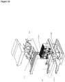
- the device comprises fans for warm air circulation 210, a cooling unit 410 comprising a warm heat exchanger 420 and a cold heat exchanger 430, and fans for cold air circulation 440.
- the housing comprises all components and serves for keeping the components together.
- a bottom insulation 450 comprises air channels for air flow.
- the device may comprise several cooling units 410.
- Figure 5 shows a top view of an exemplary setup of a device.
- the fan for cold air circulation 440 and the cold air outlet 510 are arranged closer to the first side of the housing than the cooling unit 410 comprising a warm heat exchanger 420 and a cold heat exchanger 430 in order to separate the cooling unit from the reagent compartment.
- the cooling unit 410 and the fan for warm air circulation 210 are arranged closer to the second side of the housing than the fan for cold air circulation 440 and the cold air outlet 510, also in order to separate the cooling unit from the reagent compartment.
- the fan for warm air circulation serves for cooling down the upper warm side of the cooling element and the fan for cold air circulation between cold heat exchanger and reagent compartment serves for cooling down the reagent compartment.
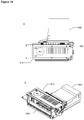
- Figure 6 illustrates the top/side view of a housing with a cooling unit and fans for cold air circulation, showing the inside of a device.
- a cooling unit 410 comprising a warm heat exchanger 420 and a cold heat exchanger 430 is mounted away from the fans for cold air circulation 440.
- the cold air outlet 510 which guides the cold air from the fan for cold air circulation 440 through an air channel 610 to a reagent compartment is also shown.
- Warm air from a reagent compartment enters the device via a warm air inlet 620.
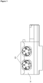
- FIG. 7 A front view of the housing of Figure 6 is shown in Figure 7 .
- a cooling unit 410 and fans for cold air circulation 440 are mounted inside the housing.
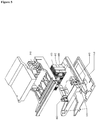
- Figure 8 illustrates the top/side view of a housing with a cooling unit and fans for warm air circulation, showing the inside of a device.
- a cooling unit 410 is mounted close to the fans for warm air circulation 210.
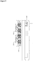
- Figure 9 shows the front view of the housing of Figure 8 comprising a fan for cold air circulation 440, a cooling unit 410 and fans for warm air circulation 210.
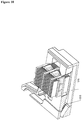
- the housing may also comprise a hole 1010 to drain condensed water or a slope 1020 to lead condensed water, as shown in Figure 10 .
- Condensed water may build up on the cold side of the cooling element.
- the inventive device allows draining of the condensed water and avoids that the warm side of the cooling element is affected by condensed water because the cooling element has an upper warm side and a lower cold side, meaning that the warm side is arranged above the cold side. Since the condensed water is naturally lead downwards, the condensed water cannot harm the warm side of the cooling element.
- the cooling units comprise a cooling element with an upper warm side and a lower cold side, a warm heat exchanger above the cooling element and a cold heat exchanger below the cooling element.
- the units are equipped with a connector for cooling element power.
- the entire cooling unit can be replaced easily by opening the housing of the device, detaching the connector and replacing the cooling units with a new one.
- the shape of the housing enforces correct insertion of a new unit.
- the housing also serves the purpose of insulation.
- the housing may also be an insulated block.
- One embodiment of the present invention comprises a device for cooling, wherein the cold heat exchanger is coupled to the cold side of the cooling element with a spacer for separating the cold heat exchanger from the cold side of the cooling element.
- a temperature sensor may be integrated in the spacer. The measurements of the temperature sensor can be used for temperature control and to prevent ice build up on the cold side of the cooling element.
- the warm heat exchanger may be directly coupled to the warm side of the cooling element for heat exchange.
- a spring may connect the warm heat exchanger and the cold heat exchanger for generating a contact force between warm heat exchanger, cooling element and cold heat exchanger.
- Figure 11 shows a cooling unit comprising a spacer.
- the spacer 1110 comprises a mounting hole 1120 to install a temperature sensor.
- the cooling element 1130 is directly mounted with the upper warm side of the cooling element to the warm heat exchanger 1140.
- Springs 1150 lower the risk of damage caused by the temperature difference between the cold side and the warm side.
- the cold heat exchanger 1160 is not directly coupled to the cold side of the cooling element 1130, but via a spacer 1110.
- the cooling element may be a Peltier element.
- Figure 12 shows a side view of a cooling unit and a cooling element.
- a spacer 1210 separates a cold heat exchanger 1220 from a cooling element 1230, which is directly coupled to the warm heat exchanger 1240.
- FIG. 13 A side view of a cooling unit is also shown in Figure 13 . It is exemplified how the springs 1310 connect the warm heat exchanger and the cold heat exchanger.
- FIG. 14 The rear view of a cooling unit is shown in Figure 14 .
- the warm heat exchanger 1410 and the cold heat exchanger 1420, which are connected by springs 1430 are shown in more detail.
- the device may also comprise a heat pipe between the cooling element and the warm heat exchanger to transfer heat.
- the heat may be transferred to a suitable part of the device.
- the cooling unit comprises an insulation attached to the warm heat exchanger and the cold heat exchanger and separating the warm heat exchanger and the cold heat exchanger from each other.
- Figure 15 shows a cooling unit comprising an insulation.
- the insulation 1510 is attached to the warm heat exchanger 1520 and the cold heat exchanger 1530.
- Springs 1540 generate the appropriate contact force between warm heat exchanger 1520, cold heat exchanger 1530 and cooling element.
- the cooling unit may also comprise an insulation surrounding the cooling element.
- Such an insulation 1610 surrounding a cooling element is shown in Figure 16 .
- Insulation generally serves the purpose of reducing heat transfer.
- the device of the present invention may comprise insulation in the housing, and the device may also comprise insulation comprised in the cooling unit. Insulation may be added wherever heat transfer is to be reduced or avoided.
- FIG 17 shows two cooling units 1710.
- the two insulation parts 1720 and 1730 on the left hand side of Figure 17A have different widths.
- Another insulation part is shown as 1740.
- the width of insulation 1720 is smaller than the width of insulation 1730.
- Figure 17B and 17C illustrate how the housing is adapted to accommodate the cooling units so that wrong insertion of the cooling units is prevented.
- the control unit of the cooling unit may measure the Seebeck voltage of the individual cooling elements. This would enable to get information about the correct functionality and performance of the cooling units.
- the present invention also provides a system for cooling a reagent compartment, wherein the system comprises the device of the present invention and a reagent compartment.
- Figure 18 shows a tops view (18A) and a front view (18B) of a system of the present invention.
- the reagent compartment 1810 comprises lanes 1820 for the insertion of reagent racks.
- the device shown as 1830, is mounted behind the reagent compartment 1810, leading to more freedom regarding the shape and material of the cooled reagent compartment.
- the reagent compartment 1810 in Figure 18 does not have a front door.
- the front opening 1840 in Figure 18B allows user access and rack insertion. Therefore, the device for cooling the reagent compartment cannot be mounted in front of the reagent compartment.
- the housing may thus be formed so that the housing accepts cooling elements with heat exchangers (warm heat exchanger and cold heat exchanger) on each side.
- the cold heat exchanger may be coupled to the cooling element with a spacer out of heat conductive material.
- the warm heat exchangers may be coupled to the cooling element directly for best heat transfer.
- An insulation may separate warm side from cold side of the cooling element.
- the housing is adapted to form the air channels for cold side and warm side air flow.
- a method for cooling a reagent compartment comprising the following steps:
- Figure 19 illustrates a top/side view of the device and the air flow through the fans for cold air circulation.
- the fans for cold air circulation 1910 initiate air flow in Figure 19A .
- Cold air exits the device via the cold air outlet 1920 to the reagent compartment.
- the air flow thus lowers the internal temperature of the reagent compartment.
- the air flows back through the warm air inlet 1930 into the device.
- Warm air 1940 comes up to the cooling element to be cooled down again.
- the cold air circulation is further shown in Figures 19B and 19C .
- the air flow of warm air 1940 and cold air 1950 is shown.
- Figure 20 shows the air flow through the fans for warm air circulation (20A: top view; 20B: side view).
- Fans for warm air circulation 2010 aspirate ambient air 2020.
- Ambient air 2020 then circulates from a bottom of the device through the warm heat exchanger and through the fan for warm air circulation 2010.
- Ambient air 2020 cools down the warm side of the cooling element to increase the cooling effect.
- the ambient air 2020 warms up when passing the warm side of the cooling element.
- Ambient air 2110 circulates from the bottom of the device through the warm heat exchanger and as warm air 2120 through the fan for warm air circulation.
- Cold air 2130 circulates from the cold heat exchanger through the fan for cold air circulation and the cold air outlet to the reagent compartment, and warm air 2120 circulates from the reagent compartment through the warm air inlet to the cold heat exchanger.
- the cooling units are separated from the reagent compartment and are mounted "upside down" compared with the state of the art.
- the warm side of the cooling element is above the cold side of the cooling element, and the cold side of the cooling element as well as the warm side of the cooling element is equipped with a cold heat exchanger and a warm heat exchanger, respectively.
- a fan for cold air circulation is circulating air between the cold heat exchanger and the reagent compartment in a closed system.
- the warm side of the cooling element is cooled with an open air flow.
Landscapes
- Engineering & Computer Science (AREA)
- Chemical & Material Sciences (AREA)
- Physics & Mathematics (AREA)
- Thermal Sciences (AREA)
- General Engineering & Computer Science (AREA)
- Mechanical Engineering (AREA)
- Health & Medical Sciences (AREA)
- Combustion & Propulsion (AREA)
- Life Sciences & Earth Sciences (AREA)
- Analytical Chemistry (AREA)
- Biochemistry (AREA)
- General Health & Medical Sciences (AREA)
- General Physics & Mathematics (AREA)
- Immunology (AREA)
- Pathology (AREA)
- Chemical Kinetics & Catalysis (AREA)
- Clinical Laboratory Science (AREA)
- Automatic Analysis And Handling Materials Therefor (AREA)
- Cooling Or The Like Of Electrical Apparatus (AREA)
- Devices That Are Associated With Refrigeration Equipment (AREA)
Claims (12)
- Eine Kühlvorrichtung (1830) zur Befestigung an einem Reagenzfach (1810) innerhalb eines automatisierten Analysesystems, umfassend ein Gehäuse mit einer ersten Seite (110) zur Befestigung an dem Reagenzfach (1810) und einer zweiten Seite (120) abgewandt von dem Reagenzfach, die der ersten Seite (110) gegenüberliegt, eine Kühleinheit (410), die nahe der zweiten Seite (120) des Gehäuses so angeordnet ist, so dass die Kühleinheit (410) maximal von dem Reagenzfach (1810) getrennt ist, wobei die Kühleinheit (410) mindestens ein Kühlelement (1130) mit einer warmen Oberseite und einer kalten Unterseite umfasst, die mit einem kälteseitigen Wärmetauscher (430) ausgestattet ist, der mindestens einen ersten Lüfter (310), mindestens einen Kaltluftkanal und mindestens eine Kaltluftöffnung an der ersten Seite des Gehäuses zum Zirkulieren von Kaltluft zwischen dem mindestens einen Kühlelement (1130) und dem Reagenzraum (1810) in einem geschlossenen System umfasst, wobei ein Abstandshalter (1110) mit integriertem Temperatursensor die warme Oberseite und die kalte Unterseite des mindestens einen Kühlelements (1130) trennt und die zweite Seite mit Lüftern zur Warmluftzirkulation (210) ausgestattet ist.
- Die Vorrichtung (1830) nach Anspruch 1, wobei der mindestens eine erste Lüfter (310) innerhalb des mindestens einen Kaltluftkanals (610) zwischen dem mindestens einen Kaltluftauslass (510) und der kalten Unterseite des Kühlelements (1130) angeordnet ist.
- Die Vorrichtung (1830) nach einem der Ansprüche 1 oder 2, ferner umfassend an der ersten Seite des Gehäuses (110) mindestens einen Warmlufteinlasskanal (620), der unten angeordnet und von dem mindestens einen Kaltluftkanal getrennt ist, um Warmluft aus dem Reagenzraum (1810) aufzunehmen und zur kalten Unterseite des mindestens einen Kühlelements (1130) zu führen.
- Die Vorrichtung (1830) nach einem der Ansprüche 1 bis 3, ferner umfassend einen warmen Wärmetauscher (430) mit mindestens einem zweiten Lüfter und mindestens einem Warmluftkanal, der zwischen der warmen Oberseite des mindestens einen Kühlelements (1130) und mindestens einer Warmluftöffnung an einer zweiten Seite des Gehäuses (120) angeordnet ist.
- Die Vorrichtung (1830) nach einem der Ansprüche 1 bis 4, ferner umfassend mindestens einen Umgebungsluftkanal, der zwischen mindestens einer Öffnung innerhalb einer dritten Seite des Gehäuses und der warmen Oberseite des Kühlelements (1130) zum Kühlen der warmen Oberseite des mindestens einen Kühlelements (1130) angeordnet ist.
- Die Vorrichtung (1830) nach einem der Ansprüche 1 bis 5, wobei die warme Oberseite und die kalte Unterseite des mindestens einen Kühlelements (1130) durch eine Isolierung (1510) voneinander getrennt sind.
- Die Vorrichtung (1830) nach einem der Ansprüche 1 bis 6, wobei das mindestens eine Kühlelement (11309) ein Peltierelement ist.
- Die Vorrichtung (1830) nach einem der Ansprüche 1 bis 7, wobei eine Feder (1150) die warme Oberseite und die kalte Unterseite des mindestens einen Kühlelements verbindet.
- Die Vorrichtung (1830) nach einem der Ansprüche 1 bis 8, wobei das mindestens eine Kühlelement (1130) so geformt ist, dass es die richtige Ausrichtung mit einer warmen Oberseite und einer kalten Unterseite des mindestens einen Kühlelements (1130) gewährleistet.
- Ein System zum Kühlen eines Reagenzfachs, umfassend eine Vorrichtung (1830) nach Anspruch 1 und das Reagenzfach (1810) in einem geschlossenen System.
- Ein Verfahren zum Kühlen eines Reagenzfachs (1810), wobei das Verfahren die folgenden Schritte umfasst:a. Bereitstellen einer Vorrichtung (1830) zum Kühlen des Reagenzfachs (1810) nach Anspruch 1 und des Reagenzfachs in einem geschlossenen System;b. Betreiben des mindestens einen Gebläses zur Warmluftzirkulation (210) und des mindestens einen Gebläses zur Kaltluftzirkulation (310), so dass kalte Luft von der kalten Unterseite des mindestens einen Kühlelements (1130) in den Reagenzraum (1810) zirkuliert und die aus dem Reagenzraum (1810) kommende Warmluft zur kalten Unterseite des mindestens einen Kühlelements (1130) zirkuliert.
- Eine Verwendung einer Kühlvorrichtung (1830) nach Anspruch 1, die an einem Reagenzfachs (1810) montiert ist, zum Kühlen des Reagenzfachs (1810).
Applications Claiming Priority (1)
| Application Number | Priority Date | Filing Date | Title |
|---|---|---|---|
| GB1509789.2A GB2539192A (en) | 2015-06-05 | 2015-06-05 | Device, system and method for cooling a reagent compartment |
Publications (2)
| Publication Number | Publication Date |
|---|---|
| EP3100788A1 EP3100788A1 (de) | 2016-12-07 |
| EP3100788B1 true EP3100788B1 (de) | 2019-02-20 |
Family
ID=53785020
Family Applications (1)
| Application Number | Title | Priority Date | Filing Date |
|---|---|---|---|
| EP16173063.5A Active EP3100788B1 (de) | 2015-06-05 | 2016-06-06 | Vorrichtung, system und verfahren zur kühlung eines reagenzfaches |
Country Status (3)
| Country | Link |
|---|---|
| US (1) | US10335794B2 (de) |
| EP (1) | EP3100788B1 (de) |
| GB (1) | GB2539192A (de) |
Families Citing this family (6)
| Publication number | Priority date | Publication date | Assignee | Title |
|---|---|---|---|---|
| KR102651375B1 (ko) * | 2019-03-18 | 2024-03-26 | 주식회사 씨젠 | 샘플 홀더 어셈블리를 포함하는 써멀 사이클러 |
| CN110045110A (zh) * | 2019-06-03 | 2019-07-23 | 思库科技(广州)有限公司 | 用于干式荧光/胶体金试剂卡检测的温控仓及温控方法 |
| CN112148041A (zh) * | 2020-08-27 | 2020-12-29 | 南京领跑生命健康产业技术研究院有限公司 | 恒温温育装置 |
| CN112473761A (zh) * | 2020-11-23 | 2021-03-12 | 石家庄禾柏生物技术股份有限公司 | 一种冷暖调温装置 |
| JP2024144884A (ja) * | 2023-03-31 | 2024-10-15 | シスメックス株式会社 | 検体測定装置及びメンテナンス方法 |
| AT527700A1 (de) * | 2023-11-10 | 2025-05-15 | Meon Medical Solutions Gmbh & Co Kg | Analysator mit Kühleinrichtung |
Family Cites Families (18)
| Publication number | Priority date | Publication date | Assignee | Title |
|---|---|---|---|---|
| DE3044372A1 (de) * | 1980-11-25 | 1982-07-08 | Boehringer Mannheim Gmbh, 6800 Mannheim | Rotoreinheit mit einsatzelementen fuer einen zentrifugalanalysator |
| US4364234A (en) * | 1981-03-25 | 1982-12-21 | Koolatron Industries, Ltd. | Control circuitry for thermoelectric environmental chamber |
| US4954237A (en) * | 1987-03-16 | 1990-09-04 | Helena Laboratories | Automatic electrophoresis apparatus |
| US5460709A (en) * | 1993-06-21 | 1995-10-24 | Helena Laboratories Corporation | Automatic electrophoresis method and apparatus |
| US6019098A (en) * | 1993-10-19 | 2000-02-01 | Hi-Z Technology, Inc. | Self powered furnace |
| US8337753B2 (en) * | 1998-05-01 | 2012-12-25 | Gen-Probe Incorporated | Temperature-controlled incubator having a receptacle mixing mechanism |
| US6370882B1 (en) * | 2000-09-08 | 2002-04-16 | Distinctive Appliances, Inc. | Temperature controlled compartment apparatus |
| JP2004205052A (ja) * | 2002-12-20 | 2004-07-22 | Yodogawa Steel Works Ltd | 台所用の保冷庫 |
| WO2006091934A2 (en) * | 2005-02-25 | 2006-08-31 | Ilercil, Alp | Biological sample preservation, transportation and storage device |
| JP2010237021A (ja) * | 2009-03-31 | 2010-10-21 | Sysmex Corp | 分析装置 |
| TW201104156A (en) * | 2009-07-28 | 2011-02-01 | Young Dong Tech Co Ltd | Light emitting diode lighting device |
| US8341967B2 (en) * | 2010-02-18 | 2013-01-01 | Golden Sun News Techniques Co., Ltd. | Heat-dissipating device for supplying cold airflow |
| JP5690501B2 (ja) * | 2010-03-29 | 2015-03-25 | シスメックス株式会社 | 検体分析装置 |
| CA3016967C (en) * | 2010-04-16 | 2021-08-31 | Opko Diagnostics, Llc | Systems and devices for analysis of samples |
| EP2912974A3 (de) * | 2010-05-28 | 2015-12-09 | Marlow Industries, Inc. | System für ein entsprechend persönlichem komfort gesteuertes thermoelektrisches Bett |
| US8999241B2 (en) * | 2011-03-16 | 2015-04-07 | Sysmex Corporation | Specimen analyzer |
| JP5877058B2 (ja) * | 2011-12-22 | 2016-03-02 | シスメックス株式会社 | 検体処理装置 |
| DE202014104040U1 (de) * | 2014-08-28 | 2014-09-29 | ELMEKO GmbH + Co. KG | Temperiereinrichtung zum Regulieren der Temperatur in einem Raum und Schaltschrank mit einer derartigen Temperiereinrichtung |
-
2015
- 2015-06-05 GB GB1509789.2A patent/GB2539192A/en not_active Withdrawn
-
2016
- 2016-06-06 US US15/173,990 patent/US10335794B2/en active Active
- 2016-06-06 EP EP16173063.5A patent/EP3100788B1/de active Active
Non-Patent Citations (1)
| Title |
|---|
| None * |
Also Published As
| Publication number | Publication date |
|---|---|
| US10335794B2 (en) | 2019-07-02 |
| GB2539192A (en) | 2016-12-14 |
| US20160354784A1 (en) | 2016-12-08 |
| EP3100788A1 (de) | 2016-12-07 |
| GB201509789D0 (en) | 2015-07-22 |
Similar Documents
| Publication | Publication Date | Title |
|---|---|---|
| US10335794B2 (en) | Device, system and method for cooling a reagent compartment | |
| CN108807726B (zh) | 具有多个电池单池的电池 | |
| US10111360B2 (en) | Electrical cabinet with improved heat dissipation | |
| US8179677B2 (en) | Immersion-cooling apparatus and method for an electronic subsystem of an electronics rack | |
| EP2917660B1 (de) | Thermoelektrische kühlvorrichtung mit einem flüssigen wärmetauscher zwischen luftwärmetauscher | |
| US8953320B2 (en) | Coolant drip facilitating partial immersion-cooling of electronic components | |
| US8964390B2 (en) | Sectioned manifolds facilitating pumped immersion-cooling of electronic components | |
| US9420730B2 (en) | Container data center | |
| US8305759B2 (en) | Gravity assisted directed liquid cooling | |
| US11937405B2 (en) | Systems and methods for cooling a fluid circuit for cooling a rack of servers | |
| CN110754005B (zh) | 用于电动车辆的电池系统 | |
| US20170261273A1 (en) | Cooling system for vehicle sensor modules | |
| CN111834692A (zh) | 电池组和这种电池组的应用 | |
| US20230006281A1 (en) | Thermal management system for an electric component | |
| US9812242B1 (en) | Systems and methods for liquid heat exchange for transformers | |
| US20210084793A1 (en) | Cooling chassis design for server liquid cooling of electronic racks of a data center | |
| US20160172726A1 (en) | Receiving device for receiving at least one energy storage component | |
| US11275415B2 (en) | Dissipating interconnection module for M.2 form factor expansion card | |
| WO2011053310A1 (en) | Cooling memory modules using cold plate blades coupled to the memory modules via clips | |
| EP2695757A1 (de) | Vorrichtung zur erwärmung eines wärmemediums und damit ausgestattete fahrzeugklimaanlagenvorrichtung | |
| US20240291070A1 (en) | Thermal regulation device for at least one electrical and/or electronic element | |
| KR101837618B1 (ko) | 전력공급장치의 냉각구조 및 이를 구비한 정수기 | |
| CN107665007A (zh) | 温控模块、温控单元及温箱 | |
| US11690202B2 (en) | High availability heterogeneity electronic rack solution | |
| US11910563B2 (en) | Liquid cooling module with movable radiators |
Legal Events
| Date | Code | Title | Description |
|---|---|---|---|
| PUAI | Public reference made under article 153(3) epc to a published international application that has entered the european phase |
Free format text: ORIGINAL CODE: 0009012 |
|
| STAA | Information on the status of an ep patent application or granted ep patent |
Free format text: STATUS: THE APPLICATION HAS BEEN PUBLISHED |
|
| AK | Designated contracting states |
Kind code of ref document: A1 Designated state(s): AL AT BE BG CH CY CZ DE DK EE ES FI FR GB GR HR HU IE IS IT LI LT LU LV MC MK MT NL NO PL PT RO RS SE SI SK SM TR |
|
| AX | Request for extension of the european patent |
Extension state: BA ME |
|
| STAA | Information on the status of an ep patent application or granted ep patent |
Free format text: STATUS: REQUEST FOR EXAMINATION WAS MADE |
|
| 17P | Request for examination filed |
Effective date: 20170607 |
|
| RBV | Designated contracting states (corrected) |
Designated state(s): AL AT BE BG CH CY CZ DE DK EE ES FI FR GB GR HR HU IE IS IT LI LT LU LV MC MK MT NL NO PL PT RO RS SE SI SK SM TR |
|
| GRAP | Despatch of communication of intention to grant a patent |
Free format text: ORIGINAL CODE: EPIDOSNIGR1 |
|
| STAA | Information on the status of an ep patent application or granted ep patent |
Free format text: STATUS: GRANT OF PATENT IS INTENDED |
|
| INTG | Intention to grant announced |
Effective date: 20180704 |
|
| GRAJ | Information related to disapproval of communication of intention to grant by the applicant or resumption of examination proceedings by the epo deleted |
Free format text: ORIGINAL CODE: EPIDOSDIGR1 |
|
| STAA | Information on the status of an ep patent application or granted ep patent |
Free format text: STATUS: REQUEST FOR EXAMINATION WAS MADE |
|
| GRAP | Despatch of communication of intention to grant a patent |
Free format text: ORIGINAL CODE: EPIDOSNIGR1 |
|
| STAA | Information on the status of an ep patent application or granted ep patent |
Free format text: STATUS: GRANT OF PATENT IS INTENDED |
|
| INTG | Intention to grant announced |
Effective date: 20181116 |
|
| GRAS | Grant fee paid |
Free format text: ORIGINAL CODE: EPIDOSNIGR3 |
|
| GRAA | (expected) grant |
Free format text: ORIGINAL CODE: 0009210 |
|
| STAA | Information on the status of an ep patent application or granted ep patent |
Free format text: STATUS: THE PATENT HAS BEEN GRANTED |
|
| AK | Designated contracting states |
Kind code of ref document: B1 Designated state(s): AL AT BE BG CH CY CZ DE DK EE ES FI FR GB GR HR HU IE IS IT LI LT LU LV MC MK MT NL NO PL PT RO RS SE SI SK SM TR |
|
| REG | Reference to a national code |
Ref country code: GB Ref legal event code: FG4D |
|
| REG | Reference to a national code |
Ref country code: CH Ref legal event code: EP |
|
| REG | Reference to a national code |
Ref country code: DE Ref legal event code: R096 Ref document number: 602016010016 Country of ref document: DE |
|
| REG | Reference to a national code |
Ref country code: AT Ref legal event code: REF Ref document number: 1097476 Country of ref document: AT Kind code of ref document: T Effective date: 20190315 |
|
| REG | Reference to a national code |
Ref country code: IE Ref legal event code: FG4D |
|
| RAP2 | Party data changed (patent owner data changed or rights of a patent transferred) |
Owner name: STRATEC SE |
|
| REG | Reference to a national code |
Ref country code: CH Ref legal event code: NV Representative=s name: 24IP LAW GROUP SONNENBERG FORTMANN, CH |
|
| REG | Reference to a national code |
Ref country code: LT Ref legal event code: MG4D |
|
| REG | Reference to a national code |
Ref country code: NL Ref legal event code: MP Effective date: 20190220 |
|
| PG25 | Lapsed in a contracting state [announced via postgrant information from national office to epo] |
Ref country code: SE Free format text: LAPSE BECAUSE OF FAILURE TO SUBMIT A TRANSLATION OF THE DESCRIPTION OR TO PAY THE FEE WITHIN THE PRESCRIBED TIME-LIMIT Effective date: 20190220 Ref country code: PT Free format text: LAPSE BECAUSE OF FAILURE TO SUBMIT A TRANSLATION OF THE DESCRIPTION OR TO PAY THE FEE WITHIN THE PRESCRIBED TIME-LIMIT Effective date: 20190620 Ref country code: FI Free format text: LAPSE BECAUSE OF FAILURE TO SUBMIT A TRANSLATION OF THE DESCRIPTION OR TO PAY THE FEE WITHIN THE PRESCRIBED TIME-LIMIT Effective date: 20190220 Ref country code: NO Free format text: LAPSE BECAUSE OF FAILURE TO SUBMIT A TRANSLATION OF THE DESCRIPTION OR TO PAY THE FEE WITHIN THE PRESCRIBED TIME-LIMIT Effective date: 20190520 Ref country code: LT Free format text: LAPSE BECAUSE OF FAILURE TO SUBMIT A TRANSLATION OF THE DESCRIPTION OR TO PAY THE FEE WITHIN THE PRESCRIBED TIME-LIMIT Effective date: 20190220 |
|
| PG25 | Lapsed in a contracting state [announced via postgrant information from national office to epo] |
Ref country code: GR Free format text: LAPSE BECAUSE OF FAILURE TO SUBMIT A TRANSLATION OF THE DESCRIPTION OR TO PAY THE FEE WITHIN THE PRESCRIBED TIME-LIMIT Effective date: 20190521 Ref country code: IS Free format text: LAPSE BECAUSE OF FAILURE TO SUBMIT A TRANSLATION OF THE DESCRIPTION OR TO PAY THE FEE WITHIN THE PRESCRIBED TIME-LIMIT Effective date: 20190620 Ref country code: HR Free format text: LAPSE BECAUSE OF FAILURE TO SUBMIT A TRANSLATION OF THE DESCRIPTION OR TO PAY THE FEE WITHIN THE PRESCRIBED TIME-LIMIT Effective date: 20190220 Ref country code: NL Free format text: LAPSE BECAUSE OF FAILURE TO SUBMIT A TRANSLATION OF THE DESCRIPTION OR TO PAY THE FEE WITHIN THE PRESCRIBED TIME-LIMIT Effective date: 20190220 Ref country code: LV Free format text: LAPSE BECAUSE OF FAILURE TO SUBMIT A TRANSLATION OF THE DESCRIPTION OR TO PAY THE FEE WITHIN THE PRESCRIBED TIME-LIMIT Effective date: 20190220 Ref country code: RS Free format text: LAPSE BECAUSE OF FAILURE TO SUBMIT A TRANSLATION OF THE DESCRIPTION OR TO PAY THE FEE WITHIN THE PRESCRIBED TIME-LIMIT Effective date: 20190220 Ref country code: BG Free format text: LAPSE BECAUSE OF FAILURE TO SUBMIT A TRANSLATION OF THE DESCRIPTION OR TO PAY THE FEE WITHIN THE PRESCRIBED TIME-LIMIT Effective date: 20190520 |
|
| REG | Reference to a national code |
Ref country code: AT Ref legal event code: MK05 Ref document number: 1097476 Country of ref document: AT Kind code of ref document: T Effective date: 20190220 |
|
| PG25 | Lapsed in a contracting state [announced via postgrant information from national office to epo] |
Ref country code: CZ Free format text: LAPSE BECAUSE OF FAILURE TO SUBMIT A TRANSLATION OF THE DESCRIPTION OR TO PAY THE FEE WITHIN THE PRESCRIBED TIME-LIMIT Effective date: 20190220 Ref country code: ES Free format text: LAPSE BECAUSE OF FAILURE TO SUBMIT A TRANSLATION OF THE DESCRIPTION OR TO PAY THE FEE WITHIN THE PRESCRIBED TIME-LIMIT Effective date: 20190220 Ref country code: EE Free format text: LAPSE BECAUSE OF FAILURE TO SUBMIT A TRANSLATION OF THE DESCRIPTION OR TO PAY THE FEE WITHIN THE PRESCRIBED TIME-LIMIT Effective date: 20190220 Ref country code: RO Free format text: LAPSE BECAUSE OF FAILURE TO SUBMIT A TRANSLATION OF THE DESCRIPTION OR TO PAY THE FEE WITHIN THE PRESCRIBED TIME-LIMIT Effective date: 20190220 Ref country code: DK Free format text: LAPSE BECAUSE OF FAILURE TO SUBMIT A TRANSLATION OF THE DESCRIPTION OR TO PAY THE FEE WITHIN THE PRESCRIBED TIME-LIMIT Effective date: 20190220 Ref country code: AL Free format text: LAPSE BECAUSE OF FAILURE TO SUBMIT A TRANSLATION OF THE DESCRIPTION OR TO PAY THE FEE WITHIN THE PRESCRIBED TIME-LIMIT Effective date: 20190220 Ref country code: SK Free format text: LAPSE BECAUSE OF FAILURE TO SUBMIT A TRANSLATION OF THE DESCRIPTION OR TO PAY THE FEE WITHIN THE PRESCRIBED TIME-LIMIT Effective date: 20190220 |
|
| REG | Reference to a national code |
Ref country code: DE Ref legal event code: R097 Ref document number: 602016010016 Country of ref document: DE |
|
| PG25 | Lapsed in a contracting state [announced via postgrant information from national office to epo] |
Ref country code: PL Free format text: LAPSE BECAUSE OF FAILURE TO SUBMIT A TRANSLATION OF THE DESCRIPTION OR TO PAY THE FEE WITHIN THE PRESCRIBED TIME-LIMIT Effective date: 20190220 Ref country code: SM Free format text: LAPSE BECAUSE OF FAILURE TO SUBMIT A TRANSLATION OF THE DESCRIPTION OR TO PAY THE FEE WITHIN THE PRESCRIBED TIME-LIMIT Effective date: 20190220 |
|
| PLBE | No opposition filed within time limit |
Free format text: ORIGINAL CODE: 0009261 |
|
| STAA | Information on the status of an ep patent application or granted ep patent |
Free format text: STATUS: NO OPPOSITION FILED WITHIN TIME LIMIT |
|
| PG25 | Lapsed in a contracting state [announced via postgrant information from national office to epo] |
Ref country code: AT Free format text: LAPSE BECAUSE OF FAILURE TO SUBMIT A TRANSLATION OF THE DESCRIPTION OR TO PAY THE FEE WITHIN THE PRESCRIBED TIME-LIMIT Effective date: 20190220 |
|
| 26N | No opposition filed |
Effective date: 20191121 |
|
| PG25 | Lapsed in a contracting state [announced via postgrant information from national office to epo] |
Ref country code: MC Free format text: LAPSE BECAUSE OF FAILURE TO SUBMIT A TRANSLATION OF THE DESCRIPTION OR TO PAY THE FEE WITHIN THE PRESCRIBED TIME-LIMIT Effective date: 20190220 |
|
| PG25 | Lapsed in a contracting state [announced via postgrant information from national office to epo] |
Ref country code: SI Free format text: LAPSE BECAUSE OF FAILURE TO SUBMIT A TRANSLATION OF THE DESCRIPTION OR TO PAY THE FEE WITHIN THE PRESCRIBED TIME-LIMIT Effective date: 20190220 |
|
| REG | Reference to a national code |
Ref country code: BE Ref legal event code: MM Effective date: 20190630 |
|
| PG25 | Lapsed in a contracting state [announced via postgrant information from national office to epo] |
Ref country code: TR Free format text: LAPSE BECAUSE OF FAILURE TO SUBMIT A TRANSLATION OF THE DESCRIPTION OR TO PAY THE FEE WITHIN THE PRESCRIBED TIME-LIMIT Effective date: 20190220 |
|
| PG25 | Lapsed in a contracting state [announced via postgrant information from national office to epo] |
Ref country code: IE Free format text: LAPSE BECAUSE OF NON-PAYMENT OF DUE FEES Effective date: 20190606 |
|
| PG25 | Lapsed in a contracting state [announced via postgrant information from national office to epo] |
Ref country code: LU Free format text: LAPSE BECAUSE OF NON-PAYMENT OF DUE FEES Effective date: 20190606 Ref country code: BE Free format text: LAPSE BECAUSE OF NON-PAYMENT OF DUE FEES Effective date: 20190630 |
|
| REG | Reference to a national code |
Ref country code: DE Ref legal event code: R082 Ref document number: 602016010016 Country of ref document: DE Representative=s name: FORTMANN TEGETHOFF PATENT- UND RECHTSANWAELTE , DE Ref country code: DE Ref legal event code: R082 Ref document number: 602016010016 Country of ref document: DE Representative=s name: FORTMANN TEGETHOFF PATENT- UND RECHTSANWAELTE, DE Ref country code: DE Ref legal event code: R081 Ref document number: 602016010016 Country of ref document: DE Owner name: STRATEC SE, DE Free format text: FORMER OWNER: STRATEC BIOMEDICAL AG, 75217 BIRKENFELD, DE |
|
| PG25 | Lapsed in a contracting state [announced via postgrant information from national office to epo] |
Ref country code: CY Free format text: LAPSE BECAUSE OF FAILURE TO SUBMIT A TRANSLATION OF THE DESCRIPTION OR TO PAY THE FEE WITHIN THE PRESCRIBED TIME-LIMIT Effective date: 20190220 |
|
| PG25 | Lapsed in a contracting state [announced via postgrant information from national office to epo] |
Ref country code: HU Free format text: LAPSE BECAUSE OF FAILURE TO SUBMIT A TRANSLATION OF THE DESCRIPTION OR TO PAY THE FEE WITHIN THE PRESCRIBED TIME-LIMIT; INVALID AB INITIO Effective date: 20160606 Ref country code: MT Free format text: LAPSE BECAUSE OF FAILURE TO SUBMIT A TRANSLATION OF THE DESCRIPTION OR TO PAY THE FEE WITHIN THE PRESCRIBED TIME-LIMIT Effective date: 20190220 |
|
| PG25 | Lapsed in a contracting state [announced via postgrant information from national office to epo] |
Ref country code: MK Free format text: LAPSE BECAUSE OF FAILURE TO SUBMIT A TRANSLATION OF THE DESCRIPTION OR TO PAY THE FEE WITHIN THE PRESCRIBED TIME-LIMIT Effective date: 20190220 |
|
| P01 | Opt-out of the competence of the unified patent court (upc) registered |
Effective date: 20230710 |
|
| PGFP | Annual fee paid to national office [announced via postgrant information from national office to epo] |
Ref country code: DE Payment date: 20250618 Year of fee payment: 10 |
|
| PGFP | Annual fee paid to national office [announced via postgrant information from national office to epo] |
Ref country code: GB Payment date: 20250620 Year of fee payment: 10 |
|
| PGFP | Annual fee paid to national office [announced via postgrant information from national office to epo] |
Ref country code: FR Payment date: 20250627 Year of fee payment: 10 |
|
| PGFP | Annual fee paid to national office [announced via postgrant information from national office to epo] |
Ref country code: IT Payment date: 20250630 Year of fee payment: 10 |
|
| PGFP | Annual fee paid to national office [announced via postgrant information from national office to epo] |
Ref country code: CH Payment date: 20250701 Year of fee payment: 10 |