EP3099539B1 - Montagemodul für ein kraftfahrzeug - Google Patents
Montagemodul für ein kraftfahrzeug Download PDFInfo
- Publication number
- EP3099539B1 EP3099539B1 EP15701663.5A EP15701663A EP3099539B1 EP 3099539 B1 EP3099539 B1 EP 3099539B1 EP 15701663 A EP15701663 A EP 15701663A EP 3099539 B1 EP3099539 B1 EP 3099539B1
- Authority
- EP
- European Patent Office
- Prior art keywords
- user
- sensor system
- light
- motor vehicle
- region
- Prior art date
- Legal status (The legal status is an assumption and is not a legal conclusion. Google has not performed a legal analysis and makes no representation as to the accuracy of the status listed.)
- Active
Links
- 238000001514 detection method Methods 0.000 claims description 155
- 230000003287 optical effect Effects 0.000 claims description 131
- 238000000034 method Methods 0.000 claims description 54
- 238000012544 monitoring process Methods 0.000 claims description 34
- 230000008859 change Effects 0.000 claims description 20
- 230000001960 triggered effect Effects 0.000 claims description 14
- 230000005540 biological transmission Effects 0.000 claims description 11
- 230000005855 radiation Effects 0.000 claims description 2
- 230000009471 action Effects 0.000 description 14
- 238000013459 approach Methods 0.000 description 10
- 230000000875 corresponding effect Effects 0.000 description 7
- 230000006870 function Effects 0.000 description 6
- 238000005259 measurement Methods 0.000 description 6
- 230000004913 activation Effects 0.000 description 5
- 230000008901 benefit Effects 0.000 description 5
- 125000002066 L-histidyl group Chemical group [H]N1C([H])=NC(C([H])([H])[C@](C(=O)[*])([H])N([H])[H])=C1[H] 0.000 description 3
- 238000011156 evaluation Methods 0.000 description 3
- 230000002452 interceptive effect Effects 0.000 description 3
- 238000013475 authorization Methods 0.000 description 2
- 238000011109 contamination Methods 0.000 description 2
- 230000008878 coupling Effects 0.000 description 2
- 238000010168 coupling process Methods 0.000 description 2
- 238000005859 coupling reaction Methods 0.000 description 2
- 230000001419 dependent effect Effects 0.000 description 2
- 238000011161 development Methods 0.000 description 2
- 230000018109 developmental process Effects 0.000 description 2
- 238000005406 washing Methods 0.000 description 2
- 241000282326 Felis catus Species 0.000 description 1
- 230000004397 blinking Effects 0.000 description 1
- 238000004891 communication Methods 0.000 description 1
- 230000007547 defect Effects 0.000 description 1
- 238000013461 design Methods 0.000 description 1
- 238000005265 energy consumption Methods 0.000 description 1
- 239000000945 filler Substances 0.000 description 1
- 238000007667 floating Methods 0.000 description 1
- 239000000446 fuel Substances 0.000 description 1
- 238000005286 illumination Methods 0.000 description 1
- 230000001939 inductive effect Effects 0.000 description 1
- 230000005693 optoelectronics Effects 0.000 description 1
- 230000010287 polarization Effects 0.000 description 1
- 230000008569 process Effects 0.000 description 1
- 230000010349 pulsation Effects 0.000 description 1
Images


Classifications
-
- G—PHYSICS
- G07—CHECKING-DEVICES
- G07C—TIME OR ATTENDANCE REGISTERS; REGISTERING OR INDICATING THE WORKING OF MACHINES; GENERATING RANDOM NUMBERS; VOTING OR LOTTERY APPARATUS; ARRANGEMENTS, SYSTEMS OR APPARATUS FOR CHECKING NOT PROVIDED FOR ELSEWHERE
- G07C9/00—Individual registration on entry or exit
- G07C9/00174—Electronically operated locks; Circuits therefor; Nonmechanical keys therefor, e.g. passive or active electrical keys or other data carriers without mechanical keys
- G07C9/00309—Electronically operated locks; Circuits therefor; Nonmechanical keys therefor, e.g. passive or active electrical keys or other data carriers without mechanical keys operated with bidirectional data transmission between data carrier and locks
-
- B—PERFORMING OPERATIONS; TRANSPORTING
- B60—VEHICLES IN GENERAL
- B60R—VEHICLES, VEHICLE FITTINGS, OR VEHICLE PARTS, NOT OTHERWISE PROVIDED FOR
- B60R25/00—Fittings or systems for preventing or indicating unauthorised use or theft of vehicles
- B60R25/10—Fittings or systems for preventing or indicating unauthorised use or theft of vehicles actuating a signalling device
-
- B—PERFORMING OPERATIONS; TRANSPORTING
- B60—VEHICLES IN GENERAL
- B60R—VEHICLES, VEHICLE FITTINGS, OR VEHICLE PARTS, NOT OTHERWISE PROVIDED FOR
- B60R25/00—Fittings or systems for preventing or indicating unauthorised use or theft of vehicles
- B60R25/20—Means to switch the anti-theft system on or off
- B60R25/24—Means to switch the anti-theft system on or off using electronic identifiers containing a code not memorised by the user
-
- G—PHYSICS
- G01—MEASURING; TESTING
- G01C—MEASURING DISTANCES, LEVELS OR BEARINGS; SURVEYING; NAVIGATION; GYROSCOPIC INSTRUMENTS; PHOTOGRAMMETRY OR VIDEOGRAMMETRY
- G01C21/00—Navigation; Navigational instruments not provided for in groups G01C1/00 - G01C19/00
- G01C21/26—Navigation; Navigational instruments not provided for in groups G01C1/00 - G01C19/00 specially adapted for navigation in a road network
- G01C21/34—Route searching; Route guidance
- G01C21/3407—Route searching; Route guidance specially adapted for specific applications
-
- G—PHYSICS
- G06—COMPUTING; CALCULATING OR COUNTING
- G06T—IMAGE DATA PROCESSING OR GENERATION, IN GENERAL
- G06T7/00—Image analysis
- G06T7/20—Analysis of motion
-
- G—PHYSICS
- G06—COMPUTING; CALCULATING OR COUNTING
- G06V—IMAGE OR VIDEO RECOGNITION OR UNDERSTANDING
- G06V20/00—Scenes; Scene-specific elements
- G06V20/50—Context or environment of the image
- G06V20/56—Context or environment of the image exterior to a vehicle by using sensors mounted on the vehicle
-
- G—PHYSICS
- G07—CHECKING-DEVICES
- G07C—TIME OR ATTENDANCE REGISTERS; REGISTERING OR INDICATING THE WORKING OF MACHINES; GENERATING RANDOM NUMBERS; VOTING OR LOTTERY APPARATUS; ARRANGEMENTS, SYSTEMS OR APPARATUS FOR CHECKING NOT PROVIDED FOR ELSEWHERE
- G07C9/00—Individual registration on entry or exit
- G07C9/00174—Electronically operated locks; Circuits therefor; Nonmechanical keys therefor, e.g. passive or active electrical keys or other data carriers without mechanical keys
- G07C9/00182—Electronically operated locks; Circuits therefor; Nonmechanical keys therefor, e.g. passive or active electrical keys or other data carriers without mechanical keys operated with unidirectional data transmission between data carrier and locks
- G07C2009/00261—Electronically operated locks; Circuits therefor; Nonmechanical keys therefor, e.g. passive or active electrical keys or other data carriers without mechanical keys operated with unidirectional data transmission between data carrier and locks the keyless data carrier having more than one function
-
- G—PHYSICS
- G07—CHECKING-DEVICES
- G07C—TIME OR ATTENDANCE REGISTERS; REGISTERING OR INDICATING THE WORKING OF MACHINES; GENERATING RANDOM NUMBERS; VOTING OR LOTTERY APPARATUS; ARRANGEMENTS, SYSTEMS OR APPARATUS FOR CHECKING NOT PROVIDED FOR ELSEWHERE
- G07C2209/00—Indexing scheme relating to groups G07C9/00 - G07C9/38
- G07C2209/60—Indexing scheme relating to groups G07C9/00174 - G07C9/00944
- G07C2209/63—Comprising locating means for detecting the position of the data carrier, i.e. within the vehicle or within a certain distance from the vehicle
- G07C2209/64—Comprising locating means for detecting the position of the data carrier, i.e. within the vehicle or within a certain distance from the vehicle using a proximity sensor
Definitions
- the invention relates to a mounting module for a motor vehicle which is suitable for providing a work signal for the motor vehicle in the event that a user is recognized in the vicinity of the motor vehicle.
- the invention also relates to a method for triggering a work signal for a motor vehicle according to independent claim 11.
- the DE 10 2008 021 989 A1 discloses a light source through which a user-visible control panel is formed.
- the control panel is limited to a small sub-area of a floor area which corresponds approximately to the size of two shoe prints.
- the control panel is formed when an approach to people has been detected by a sensor that is not mentioned in detail. The user can deliberately touch the control panel with one foot and thus start an authentication check for an access authorization.
- the disadvantage here is that approaching people must first be detected with a further sensor before the authentication check is started.
- the user must already be close to the motor vehicle and consciously step onto a visible control panel.
- the user has to take action to start the authentication check. This is time consuming for the user.
- the invention has a mounting module for a motor vehicle according to claim 1.
- only one optical sensor system is integrated in the assembly module, which on the one hand monitors the detection area and on the other hand monitors the actuation area that differs from the detection area, in particular can recognize to what extent a user is in the detection area and / or in the actuation area . Since only one optical sensor system is used to check the two areas outside the vehicle, the number of components in the assembly module can be significantly reduced. Only when the user is in the detection area does the optical sensor system ensure that the authentication check between the ID transmitter and the motor vehicle starts and, in the case of a positive authentication, i.e. when the authorized user is in the detection area, takes place via the optical Sensor system monitoring of the operating area. In order to finally trigger the work signal for the vehicle, it is necessary for the user to move into the actuation area that is recognized by the optical sensor system.
- the optical sensor system advantageously has a control device which is responsible for monitoring the detection area and / or for recognizing the user in the detection area and for triggering the authentication check and / or for monitoring the operating area and / or for triggering the work signal for the motor vehicle is. It is also conceivable that the assembly module has individual control unit modules that are each responsible, independently of one another, for monitoring the detection area, for triggering the authentication check, for monitoring the actuation area and for providing the work signal. These individual control unit modules are advantageously integrated in the optical sensor system. Furthermore, it can be essential to the invention that through the use of the optical sensor system the recognition of a user can be defined in the predetermined detection area, which can be defined as a spatial section, outside the motor vehicle.
- the larger shapes of the detection area result from the structure of the optical sensor system, whereby it is possible to define the detection area so that the user is recognized in the detection area before a work signal is triggered.
- the user can thus be identified earlier than when using a capacitive sensor, as is described in the prior art.
- the optical sensor system has a sensor and a light module with which light can be emitted in order to create a detection area, the sensor being designed to receive light from the detection area and / or the actuation area, in particular the detection area for the user is not visible.
- the mounting module can be designed with a light module that has a plurality of light sources.
- the light module advantageously emits IR rays.
- the light is used to create the detection area. It can be provided that the detection area is invisible to the user.
- the light sources and / or the light module can be arranged around the optical sensor. So z. B. light sources can be arranged to the left and right of the optical sensor. Alternatively, the light sources can be arranged around the circumference of the optical sensor.
- the light can also be laser light.
- the assembly module provides a display element in order to create the actuation area, the actuation area in particular being visible to the user.
- the actuation area is advantageously only created when a positive authentication check is present.
- the user can carry out a corresponding action and / or movement within the actuation area, whereby the work signal can be triggered.
- the sensor system monitors the operating area and can decide according to defined criteria to what extent within the Operating range the user has taken the "correct" action to trigger the work signal.
- the display element can be designed, for example, to generate the visible actuation area on the floor surface on which the motor vehicle is also standing.
- the actuation area can also be at a corresponding height, that is, at a distance from the floor surface, on the motor vehicle. For example, it is conceivable that the actuation area is approximately at the level of the optical sensor system.
- the assembly module can be arranged in a receptacle which is designed for mounting the assembly module on the motor vehicle, in particular the assembly module or the receptacle can be suitable to be attached to the rear of the vehicle or on a side of the vehicle, in particular the assembly module can be in a handle strip of the motor vehicle be integrated, wherein the receptacle can be arranged on an emblem of the motor vehicle.
- the handle bar can, for. B. be arranged on the tailgate of the motor vehicle.
- the handle bar can be in the area of the door handle. Consequently, the operating range can be in the area of the door handle.
- the actuation area can also simply have a predetermined distance or distance area from the display element that is known to the user.
- the user if the user is recognized in the actuation area, the user's will is recognized by a predefined movement.
- the predefined movement can be the movement of a body part of the user in or on the actuation area.
- the predefined movement can additionally or alternatively be the movement of a body part of the user in the actuation area and / or out of the actuation area.
- the body part can be a foot or a hand of the user. It can also be the case that the predefined movement is defined more precisely, for example the predefined movement can correspond to a predetermined gesture.
- the invention can also provide that the sensor system is designed in such a way that the detection area is divided into at least two zones, a near zone and a far zone, the near zone being at a smaller distance from the sensor system than the far zone, with recognition of the user according to b) of claim 1 only takes place, when the user is in the near zone.
- the sensor system is configured in such a way that constant and permanent detection area monitoring is carried out, with the user in the far zone advantageously already being recognized by the sensor system, but not yet starting an authentication check that would require additional energy from the motor vehicle. Only when the user is in the near zone that is detected by the sensor system is a signal triggered to start the authentication check.
- the mounting module can be designed such that the light module and / or the sensor have a lens system, the lens system in particular having a filter. It can be provided that the lens system, in particular the sensor, has an infrared filter, as a result of which interfering light can be filtered out.
- the stray light can be, for example, sunlight or light from an artificial light source, e.g. B. garage light act.
- the light module can also have a polarization filter.
- the optical sensor system is designed with the control unit for evaluating the optical sensor.
- the control unit can be designed to evaluate images that have been recorded by the optical sensor. These can be images of the detection area and / or the actuation area.
- the optical sensor system is designed to record identification images and comparison images and, if necessary, to evaluate them. Identification images are created with the help of the reflection of the light emitted by the light module. Comparison images are created with the help of the stray light. The light module does not emit any light in order to generate the comparison images.
- the control unit can recognize the interfering light by comparing a recognition image and a comparison image. The control unit can thereby generate a modified recognition image from which the interfering light has been removed.
- the optical sensor system can be designed in such a way that a comparison image is recorded after a predetermined number of detection images. The measures mentioned make it possible for the optical sensor system to generate an image that is only generated by the light of the light module. The control unit can immediately recognize the user.
- control unit evaluates the images received from the optical sensor according to specified criteria.
- the control unit can finally trigger the signal for the start of the authentication check.
- the optical sensor system can check a defined requirement for recognizing the user in the far zone.
- the size of the object in the far zone can be checked by the optical sensor system.
- it can be a different requirement than the one that is checked in the near zone.
- a requirement in the far zone is preferably selected which requires less electrical power than the requirement in the near zone. It is possible that a measurement of the distance between the object and the optical sensor is only carried out in the near zone. This division can also save electrical power.
- the optical sensor can be an LDPD sensor (Lateral Drift Field Photodetector).
- a CMOS sensor can also be used within the optical sensor system.
- the mentioned optical sensors record images of the detection area or the actuation area. Each image can in particular be composed of a total number of pixels.
- the optical sensor may include an image sensor that includes the total number of pixels.
- the LDPD sensor is particularly suitable for being evaluated quickly and, at the same time, for low-energy work.
- the optical sensor system can advantageously be designed in such a way that the detection area is at least partially above a floor surface on which the motor vehicle is standing, in particular that the sensor system has a rigid lens system. It is conceivable here that the optical sensor system is designed to permanently monitor the detection area when the motor vehicle is parked until authentication is successful. In this case, permanent can mean that the optical sensor system is designed to record and / or evaluate an image after every predetermined time period t. In particular, the time period t 1 ms t 3 s, preferably 0.05 s t 0.05 s. The optical sensor system can permanently monitor the detection area from the time the motor vehicle is parked until the authentication is successful. The permanent monitoring can, for example, from the time be carried out after no ignition key is inserted and / or the motor vehicle is locked and left by the user.
- z. B. provide a battery of the motor vehicle to the optical sensor system and / or the authentication system electrical power.
- the optical sensor system In order for the parked motor vehicle to be functional even after several weeks in the parked state, it is necessary for the optical sensor system to require only a small amount of electrical power. The following measures serve this purpose. So z. B. the optical sensor system require a low electrical power when emitting the light and / or a low power when evaluating the optical sensor.
- the optical sensor system can be designed in such a way that the signal for starting the authentication check is only seldom triggered. This will u. a. achieved in that the detection area has a near zone and a far zone.
- the advantage of a rigid lens system is that the lens system can monitor both the detection area and the actuation area. This means that only one lens system is used for the detection area and the actuation area.
- the light module has a distance d to the optical sensor, which in particular has an amount of approximately 1 cm d 3 cm, preferably approximately 2 cm, and / or that the sensor system is designed such that the detection area is approximately extends up to 2m. It has advantageously been shown that as many light beams as possible from the light module also reach the receiving area of the optical sensor, so that the light module has to emit light of a low intensity. As a result, the light module has to consume less electrical power.
- the work signal can advantageously be a signal for unlocking and / or locking and / or opening and / or locking a moving part of the motor vehicle, wherein in particular the movable part is a tailgate or a side door or a sliding door.
- the tailgate and / or the side door can be designed as a sliding door.
- the moving part can be unlocked.
- the work signal can be a signal that activates a motorized opening and / or closing aid.
- the motor vehicle has an engine that completely opens and / or closes the moving part.
- the signal for opening and / or closing the movable part can in particular be a signal to an electromechanical door lock.
- the optical sensor system initiates a passive keyless entry check.
- a passive keyless entry check is understood to mean a method in which an authentication check takes place unnoticed by the user. In the case of a passive keyless entry check, the user does not have to initiate the authentication check with a conscious act.
- the detection area can preferably decrease in size towards the optical sensor system. In this way, only users are specifically recognized who are likely to approach the optical sensor system and / or the motor vehicle.
- the mounting module can, for. B. be designed to be installed so that the detection area is at least partially above a floor surface on which the motor vehicle is located.
- the detection area is not limited to just a small sub-area of a floor area in front of a motor vehicle.
- the detection area and / or the actuation area ends at the floor surface.
- the detection area and / or the actuation area can end at least partially above the floor surface.
- the detection area and / or actuation area is located completely above the floor surface, in particular at a defined distance from the floor surface.
- the light module and the display element can advantageously be aligned in such a way that the actuation area is closer to the motor vehicle than the detection area, in particular that two actuation areas are provided.
- the actuation area can lie within the detection area, the detection area being made larger than the actuation area.
- the optical sensor system is configured in such a way that, after a defined time t, the actuation area or areas must be "addressed" in accordance with a predefined action or gesture of the user. If this is not the case, it is not possible to provide the work signal for the vehicle.
- the mounting module can, for. B. be used in the rear of the motor vehicle, the display element can also be used as a license plate light. Additionally and / or alternatively, it can be provided that the assembly module is designed for arrangement in an emblem of the motor vehicle. Alternatively and / or additionally, the mounting module can be suitable for on a motor vehicle side. B. to be attached in a B-pillar. As a result, different detection areas, in which a user usually approaches the motor vehicle, can be monitored with the optical sensor system. Here, too, after a positive authentication check, the actuation area is provided by the optical sensor system.
- the optical sensor system is advantageously configured such that a change in distance is calculated in the near zone of the detection area and / or in the actuation area when the user is in the near zone or in the operating area.
- measurements are made in particular for at least two successive images, in particular identification images.
- the distance can be carried out by a time of flight measurement. It may be that the optical sensor has a resolution at which 2 pixels correspond to the area of the body part. A variation of the pixel size is also conceivable. By choosing the pixel size, energy can be saved, which the optical sensor system needs for monitoring the outside area of the motor vehicle.
- the light module for monitoring the detection area can advantageously emit the same light with regard to the wavelength and / or the duration of a light pulse as for monitoring the actuation area.
- the structure of the optical sensor system is preferably not changed.
- the light module for monitoring the detection area can thus have the same transmission area as for monitoring the actuation area.
- the optical sensor for monitoring the detection area can also have the same reception area as for monitoring the actuation area.
- a cost-effective optical sensor system for the assembly module can thus be provided.
- the control unit of the optical sensor system since the actuation area preferably has a smaller spatial extent than the detection area, it can be advantageous that the control unit of the optical sensor system only evaluates a small part of the image recorded by the optical sensor when monitoring the actuation area. This part corresponds to the picture of the operating area.
- the number of pixels evaluated can be less than the total number of pixels. This also makes it possible to provide low-energy operation of the sensor system.
- the display element can also be integrated within the optical sensor system. It is also conceivable that the display element can be attached to the motor vehicle at a distance from and structurally separate from the optical sensor system.
- the optical sensor system or the entire assembly module for arrangement on the rear of the vehicle, for. B. behind the rear window, in a handle bar, in a Emblem, in a tail light, behind a cat's eye, on a bumper and / or in a gap between two components.
- the mounting module may be suitable for on one side of the vehicle. B. to be attached in a B-pillar.
- the optical sensor system or the entire assembly module can be covered behind a layer which is opaque from the outside but which is transparent to the light of the optical sensor system. So z. B. the bumper on which the optical sensor system is mounted, be painted.
- the optical sensor system is preferably arranged on the motor vehicle in such a way that it is not very dirty.
- the optical sensor system can be arranged behind the rear window in the wiping area of the windshield wiper or on the handle strip.
- the assembly module can have a washing nozzle with which the optical sensor system can be cleaned.
- the washing nozzle can here, for. B. always automatically clean the optical sensor system when the wiper of the front and / or rear window is operated.
- a clean optical sensor system requires a lower light intensity in order to function, so that this also saves energy.
- the intensity of the emitted light can depend on the brightness of the ambient light.
- the brightness of the ambient light can be determined by a brightness sensor.
- the object must be removed from the actuation area within a predetermined distance in order for the signal to be provided. Removing an object within a predetermined distance can be part of the gesture.
- the beginning of the removal period is for the User noticeable. So z. B. assume a display element several lighting states. In one of the lighting states, such a display element can emit light of constant brightness. In a different lighting state, for. B. the brightness change periodically. So z. B. the beginning of the actuation period emit the display element light of constant brightness. During the removal period, the display element can e.g. B. blink.
- the signal is only provided if the object, in particular a part of the body of the user, is removed from the actuation area within the distance period.
- the assembly module and / or motor vehicle has at least one means that makes it easier for the user to indicate the user's will in the actuation area, so that the signal is triggered.
- the assembly module can send out a signal that the actuation time will end shortly.
- the notification signal can e.g. B. start by changing the lighting state of the display element.
- the notification signal can correspond to a different lighting state of the display element.
- the display element can flash at the end of the actuation period.
- the means corresponds to a corresponding method specification in the monitoring unit.
- the assembly module and / or the motor vehicle can have means by which a perceptible, in particular visible, audible or tactile signal can be generated for the user.
- the mounting module can light elements such. B. LEDs have.
- the lighting elements can be arranged in such a way that the lighting elements act as signposts.
- the lighting elements can be aligned in such a way that they generate markings on the floor surface that lead to the actuation area.
- the lighting elements can be arranged next to one another. The light elements can be switched on in an order that shows the user in which direction the user has to move towards the actuation area.
- light elements arranged side by side in the motor vehicle e.g. B. the lighting elements of a headlight, a brake light, blinker or the like can be used. It is also conceivable to give the user an acoustically audible instruction in which direction the user must move.
- the assembly module can have a loudspeaker. It is also conceivable to inform the ID transmitter of the change in direction, which uses various vibrations to show the user the way. If the user is informed of a change in direction, the optical sensor system determines the position of the user and the direction in which he must move to the actuation area and causes the perceptible means to send out the corresponding signal.
- the position of the actuation area and / or the length of the actuation duration can be changed. This is particularly helpful if a physically handicapped user wants to express his / her will to use it. This is also helpful if the actuation area is arranged in a position that is unfavorable for the user.
- the unfavorable position can be permanent.
- the operating range can end on a trailer coupling.
- the unfavorable position can only be unfavorable for triggering a one-time work signal, e.g. B. because the operating area ends at a puddle.
- a predefined user action can in particular be provided. So z. B. the user the position of the operating area and / or length of the duration of the operation by an entry in a user menu, z. B. a vehicle control unit or an ID transmitter, change.
- the predefined user action can be recognized by the optical sensor system.
- the assembly module can be transferred to a learning mode in which the assembly module learns the changed position of the actuation area and / or the changed length of the actuation area.
- the actuation area is monitored again in order to determine a user willingness to trigger a work signal after a first actuation period has ended without recognition of the user's will. This is particularly helpful if the user was distracted and did not reach the operating area in time or performed the wrong gesture.
- the actuation area can be monitored several times, in particular two or three times, one after the other.
- the renewed monitoring of the operating area can be initiated automatically.
- a predefined user action can be provided in order to monitor the actuation area again for a further actuation period.
- a capacitive sensor can be addressed by the user.
- it can be a predefined user action that is recognized by the optical sensor system.
- the predefined user action which is recognized by the optical sensor system and which causes a change in the position of the actuation area and / or the duration of the actuation and / or a renewed monitoring of the actuation area in order to recognize a user's will, can be, for example, the following user actions: a predetermined gesture within the actuation and / or detection area, for example a back and forth movement of a body part of the user, non-removal of the body part, if removal was intended, a movement of the user into the detection and / or actuation area and / or out of the Detection and / or actuation area.
- the body part can be a hand or a foot. It can further be provided that the user leaves the detection area for a predetermined time and then returns to the detection area.
- the display element also shows this. If the position of the actuation area is changed, the display element shows this.
- the display element can have several light sources, e.g. B. LEDs on. One or more illuminants each make an actuation area at least partially visible.
- the actuation area with the changed position is preferably within the detection area.
- the corresponding pixels are evaluated depending on which actuation area is monitored.
- a position of the ID transmitter is checked during or after authentication and before the signal is triggered.
- the strength of a signal sent by an ID transmitter can be used for this purpose.
- the Receive Signal Strength Indicator (RSSI) can be used for this.
- RSSI Receive Signal Strength Indicator
- determining the strength of the transmitted signal can, for. B. can be determined whether the user is in front of, next to or behind the motor vehicle. This can ensure that only the authorized user himself has entered the detection area and has made known his / her intention to use in the actuation area. It is conceivable to poll the RSSI cyclically.
- Energy can also be saved by using light of different wavelengths.
- the monitoring of the detection area up to the one-time detection of any object in the detection area can take place with light of a longer wavelength than the subsequent checking of further requirements that are placed on the detection of a user. So initially z. B. light with a wavelength of 905 nm can be used. If an object is found in the detection area, z. B. light with a wavelength of 800 nm can be used. Alternatively, the wavelength can be shortened when the object changes from the far to the near zone.
- the advantages of the method according to the invention essentially correspond to the advantages described with regard to the assembly module according to the invention.
- the method according to the invention is preferably a method that can be carried out with the assembly module, as described above.
- the authentication can be a passive keyless entry check.
- the detection area is advantageously continuously monitored.
- the optical sensor system requires little energy to reliably monitor the detection area.
- the detection area is advantageously divided into at least two zones, a near zone and a far zone, the near zone being at a smaller distance from the sensor system than the far zone, the user being recognized according to step b) only when the user is in the near zone.
- the sensor system can emit light in the area that is not visible to the user. It is conceivable that the sensor system emits pulsed light.
- the invention can provide that the sensor system can be switched between a rest mode and a working mode, the sensor system being switched in the rest mode until the user reaches the near zone. This allows energy to be saved while the method is in operation.
- the pulse frequency is advantageously lower in the rest mode than in the working mode. It can also be that several light pulses are emitted one after the other by the light module in order to be able to generate an image. The light pulses can be integrated or summed up in order to generate the image. Likewise, in step a) during monitoring of the detection area or in step d) during monitoring of the actuation area, the control unit can only evaluate part of the image recorded by the optical sensor. Here too, energy can be saved.
- An access control system of a motor vehicle will preferably send a wake-up signal to the ID transmitter in accordance with step b).
- An authentication code is then sent from the ID transmitter to an access control system of the motor vehicle.
- the access control system compares the authentication code with a stored code. In the event of a match, a signal, in particular an unlocking signal and / or a signal for monitoring the actuation area, can optionally be triggered. Step c) or step d) can thus be carried out.
- the method advantageously has a display element that emits light in the visible range for step c) in order to create an actuation area for the user, in particular that the actuation area is in the detection area.
- the spatial design of the actuation area is smaller than the detection area.
- the actuation area is advantageously at a smaller distance from the motor vehicle, in particular from the sensor system, than the detection area.
- the sensor system can have a sensor that receives light from the detection area and / or actuation area, the sensor system having a control unit that evaluates the data from the sensor.
- the method according to the invention includes a sensor system that emits a large number of light bundles, in particular light cones, which, when put together, can form the detection area and / or the actuation area.
- the sensor system can thus have a plurality of light sources which emit pulsed light into the detection area.
- the pulsed light is advantageously in the invisible wavelength range, so that the user is recognized unnoticed in step b), as a result of which the authentication check also takes place unnoticed.
- the actuation area is advantageously located within the detection area, the actuation area differing in its dimensions from the detection area, in particular the actuation area is smaller than the detection area. If the user performs a conscious action within the operating area, the user is still in the detection area, the light module continuing to emit light in the non-visible area in step c).
- This light is advantageously pulsed so that a change in distance can also be determined in the actuation area, which change occurs due to a movement of the user in the actuation area. Only when there is a defined change in distance does the control unit decide that the work signal is provided for the motor vehicle.
- a measure improving the invention can provide that the sensor system carries out a check of a change in distance in order to detect in the detection area and / or in the To detect a user who is approaching the motor vehicle operating area, in particular the sensor system only checks a change in distance when the user is in the near zone. This saves energy during the permanent monitoring of the detection area.
- the method according to the invention can be designed in such a way that the sensor system receives and / or records images of the detection area and / or the actuation area, the images being pulsed images and unpulsed images, the pulsed images being caused by the reflection of an emitted, pulsed light of the Sensor system arise and the unpulsed images are created by the light of the detection area and / or actuation area, the pulse frequency of the emitted light being lower in the idle mode than in the working mode.
- the user is recognized in accordance with step b) or in accordance with d) only when the user moves in the detection area or in the actuation area.
- the pixels that depict the object can be compared from two images recorded one after the other, in particular recognition images.
- a distance between the object and the optical sensor can be measured in the case of at least two images recorded one after the other, in particular detection images. If different distances are detected, the object has moved in the detection area or in the actuation area.
- a time of flight measurement can be carried out, for example.
- step b) a user is only recognized in the detection area when the object in the detection area approaches the optical sensor system and / or the motor vehicle. This means that it is not just a simple movement of the object in the detection area that is sufficient to trigger the signal to start the authentication check. Only when the distance between the object and the optical transmitter and / or the motor vehicle is reduced is a signal triggered to start the authentication check.
- the distance between the object and the optical sensor is determined in the case of at least two consecutive images, in particular recognition images, measured. A time of flight measurement can be carried out to measure the distance.
- Step b) is only triggered by a significant approach of a user or an object within the detection area. In particular, when the object or the user comes into the near zone, step b) takes place.
- each image can also be composed of a total number of pixels, with only a number of pixels being checked for checking the detection area and / or the actuation area which is less than the possible total number of pixels.
- the requirements for recognizing a user in step b) and / or d), i.e. the detection duration, the size of the object, the movement of the object, the approach of the object, etc., can be combined as desired.
- the object may have a predetermined size and must approach the optical sensor in order to be recognized as a user and to trigger a signal to start an authentication check.
- the method according to the invention can have a sensor system with a light module that emits light so that a transmission area is created, the sensor having a reception area which at least partially overlaps with the transmission area, the area of intersection being the detection area.
- the detection area can be formed by the superposition of a transmission area of the light module and a reception area of the optical sensor.
- the transmission range of the light module results from the range from which the light module emits light of sufficient intensity.
- the reception area results from the area from which the optical sensor can receive light.
- the transmission range of the light module can be composed of the transmission ranges of the individual light sources. Alternatively, the transmission range can be limited to the superposition of the transmission ranges of the individual light sources.
- the ID transmitter preferably sends an authentication code to the access control system of the motor vehicle during step b), the access control system comparing the authentication code with a stored code and, if they match, an unlocking signal is triggered.
- Step d) advantageously takes place only in the case of a defined movement of a part of the user's body in / on the actuation area, the part of the body being a foot or a hand of the user.
- the actuation area is on the floor on which the user has to put his foot for step d), in particular the user only has to put his foot for a defined time in order to trigger a work signal. This can mean that the user has to put his foot on the ground defined by the actuation area.
- the method can be carried out in such a way that within a defined time window the user has to put his foot into the actuation area. If this is not done by the user, step d) cannot be triggered.
- the actuation area is at a distance from the floor and from the sensor system, the actuation area in particular having a hologram.
- the actuation area can for example be at the level of the sensor system, for example at a short distance from the motor vehicle. The user only has to enter this operating area with a body part in order to generate the work signal for the motor vehicle.
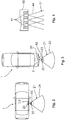
- Figure 1 shows a mounting module 20 that can be used in a motor vehicle 1.
- the mounting module 20 has an optical sensor system 30 which is suitable for the near To monitor the environment of the motor vehicle 1.
- the assembly module 20 is electronically connected to motor vehicle electronics that are integrated in the motor vehicle 1, with a work signal for the motor vehicle 1 being able to be generated via recognition of a user 10, for example in order to unlock and / or lock and / or open and / or To trigger the closure of a movable part 2, 3 of the motor vehicle 1.
- the movable part 2, 3 can, for. B. be a tailgate 2 or a side door 3 or a sliding door 3.
- the optical sensor system 30 has an optical sensor 50 and a light module 40, wherein the light module 40 can emit light 44, whereby a detection area 21 is created.
- the assembly module 20 comprises a display element 43 which can create an actuation area 22.
- the light module 40 has a large number of light sources 41, which are shown in FIG Figure 4 and Figure 11 is shown schematically.
- the light module 40 also has a distance from the optical sensor 50 which, in the present exemplary embodiment, can be in a range d which is between 1 cm d 3 cm.
- the optical sensor 50 is designed in such a way that light 44 is received from the detection area 21 and / or from the actuation area 22. In the exemplary embodiments shown, the detection area 21 is not visible to the user 10, the light module 40 being designed in such a way that the emitted light 44 is IR rays.
- the light module 40 according to Figure 1 may have a lens system 42 which, for example, may also be designed with a filter that is not explicitly shown.
- a control unit 60 is shown which is suitable for evaluating data from sensor 50.
- the control unit 60 can take on further functions, which will be discussed below.
- the control unit 60 is advantageously integrated within the assembly module 20. It can also be conceivable for the control unit 60 to be arranged on the motor vehicle side, with an electronic connection between the control unit and the assembly module 20 or the optical sensor system 30.
- the mounting module 20 is arranged in a receptacle 25 which is designed for mounting the mounting module 20 on the motor vehicle 1.
- the assembly module 20 and / or the receptacle 25 are according to all exemplary embodiments suitable, on the rear of the vehicle ( Figure 3 , Figure 5 , Figure 6 and Figure 8 ) or on one side of the vehicle ( Figure 2 and Figure 7 ) to be ordered.
- the assembly module 20 can be attached to the B-pillar 4 of the motor vehicle 1 (see Fig. Figure 7 ) are attached.
- the invention also includes that the assembly module 20 according to the invention is at least partially in the door handle 5, as in Figure 7 is shown schematically, is integrated.
- Figure 1 shows that the assembly module 20 is provided on a handle strip 6 of the motor vehicle 1, wherein the handle strip can be part of a door handle or a rear handle, for example.
- the optical sensor 50 can also be equipped with a lens system 51, which is shown in FIG Figure 1 is shown.
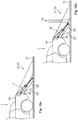
- Figure 8 and Figure 9 the exemplary embodiment is shown in which the mounting module 20 is provided in an emblem 80 of the motor vehicle 1.
- the light module 40 and the display element 43 are aligned such that the actuation area 22 is significantly smaller than the detection area 21.
- the optical sensor system 30 has a lighting element 45 in order to make different lighting states visible for the user 10, which are exemplified in FIG Figure 14 are shown.
- the lighting element 45 can also work as a display element 43, which will be discussed below.
- the emblem 80 has different fields 81, one of the following components being arranged in each field 81: light module 40, display element 43, optical sensor 50. It can also be provided that the lighting element 45 can be integrated in one of the fields 81.
- the emblem 80 is movably arranged on the motor vehicle 1. In a first position z. B. the optical sensor system 30 protected behind the emblem 80 are located. In a second position, it is conceivable that the detection area 21 and / or the actuation area 22 can be checked.
- the display element 43 is arranged on the motor vehicle side and not in the assembly module 20.
- the display element 43 is in electrical connection with the control unit 60.
- FIG Figure 1 It is also shown in FIG Figure 1 It is conceivable to provide an emergency actuation 90 within the assembly module 20, whereby an activation of the emergency actuation 90 with a body part 12 of the user 10 generates a work signal for the Vehicle 1 can be provided.
- This emergency actuation 90 enables the user 10 to trigger the above-mentioned work signal for the motor vehicle 1 if the optical sensor system 30 is contaminated or if the functionality is disturbed. In such a case, the emergency actuation 90 can be activated by the user 10 in order to trigger the work signal for the motor vehicle 1.
- the emergency actuation 90 has an activation means 91 which, for. B. can be a button or a switch, wherein the activation means 91 can function capacitive or inductive or contactless.
- the activation means can also be a piezo element. If the sensor system 30 has a higher level of contamination, so that the optical sensor system 30 cannot adequately monitor the detection area 21 and / or actuation area 22, the sensor system 30 is able to be operated with increased power, whereby a satisfactory monitoring of the detection area 21 and / or the actuation area 22 is possible.
- the optical sensor system 30 can according to Figure 1 monitor the area outside of the motor vehicle 1, in particular monitor a detection area 21, the detection area being divided into a near zone 23 and a far zone 24.
- the near zone 23 is at a smaller distance from the sensor system 30 than the far zone 24.
- the sensor system 30 according to the invention permanently monitors the detection area 21, even if the user 10 is outside the detection area 21.
- the monitoring of the detection area 21 is also shown schematically in FIG Figure 14 shown with the reference numeral 100. If the user 10 now reaches the near zone 23 within the detection area 21, there is a signal for the start of an authentication check between an ID transmitter 13, which the user carries with him, and the motor vehicle 1, which is identified by the reference numeral 110 according to FIG Figure 14 is shown schematically.
- method step 120 takes place according to Figure 14 , in which an actuation area 22 located outside the motor vehicle 1 and differing from the detection area 21 is monitored.
- the sensor system 30 emits light in the area that is not visible to the user, which creates the detection area 21.
- the sensor system 30, in particular the light module 40 advantageously sends out pulsed light.
- the user 10 can now the Activate actuation area 22 via a defined movement, gesture, etc., which is detected by sensor system 30.
- the work signal is provided for the motor vehicle 1, which in method step 130 according to FIG Figure 14 is shown.
- the assembly module 20 can be in data communication with an access control system 14 of the motor vehicle 1, for example a door lock 8 can be addressed accordingly via the work signal so that it can unlock and / or lock in order to open or close a tailgate or a door of the motor vehicle 1, for example to be able to.
- the defined gestures of the user 10 in the actuation area 22 can be different, for example it can be provided that the user 10 steps with his foot 11 on the visible actuation area 22 (see FIG Figure 6 ).
- a further variant is shown in which two actuation areas 22 are visualized which the user 10 has to activate in order to carry out the method step with the reference symbol 130 according to FIG Figure 14 to activate.
- the detection area 21 is permanently monitored, in particular also when the user according to Figure 1 is located outside the detection area 21.
- the light module 40 continues to emit invisible light when monitoring the actuation area 22, whereby the detection area 21 is formed, the optical sensor 50 checking the actuation area 22 at the same time.
- the sensor 50 receives light from the detection area 21 and light from the actuation area 22.
- These data and / or signals are recorded by the image sensor 50, the control unit 60 evaluating the data.
- the control unit 60 can also be integrated in the image sensor, in particular the optical sensor 50.
- the sensor system 30 can emit a multiplicity of light bundles 44 which, when put together, form the detection region 21.
- the light module 40 thus has a large number of light sources 41, each of which emits individual light bundles 44 into the outside area of the motor vehicle 1 in order to create the detection area 21.
- One advantage here is that the light intensity of the individual light sources 41 are significantly reduced can, whereby the power consumption of the optical sensor system 30 can be reduced.
- the sensor system 30 is shown schematically, which in FIG Figure 1 and in the other exemplary embodiments, a check of a change in distance can be carried out in order to identify a user 10 who is approaching motor vehicle 1 in detection area 21 and / or in actuation area 22.
- the light module 40 emits invisible light in the direction of the actuation area 22, which light requires the time t 1 to leave the light module 40 and to be received by the optical sensor 50. If a user 10 approaches the actuation area 22, which is shown in FIG Figure 15 b, the light 44 requires the time t 2 to travel from the light beam 40 to the optical sensor 50.
- the method according to the invention thus receives the valuable information that a user 10 is approaching motor vehicle 1.
- the sensor system 30 can receive images of the detection area 21 and of the actuation area 22.
- the images are advantageously pulsed images and unpulsed images, the pulsed images being produced by a reflection of an emitted, pulsed light 44 from the sensor system 30 and the unpulsed images being produced by the light from the detection area 21 and the actuation area 22.
- pulsed light interference lights can be effectively calculated out of the environment, so that a reliable monitoring of the detection area 21 and the actuation area 22 can be carried out.
- the sensor system 30 can be switched between a rest mode 31 and a working mode 32, which is in Figure 14 is shown.
- the sensor 50 is shown schematically with the light sources 41 arranged adjacent thereto.
- the display element 43 can be integrated in the light module 40. It is also It is conceivable to arrange the display element 43 at a distance from the light module 40.
- the sensor 50 has a plurality of grid-shaped pixels.
- Figure 12 indicates the sleep mode 31 of the optical sensor 50, in which only half of the pixels are evaluated.
- Figure 9 indicates the working mode 32 in which only 4 pixels are checked and evaluated, which correspond to the actuation area 22. The remaining pixels are not evaluated. The pixels shown in white according to Figure 8 and Figure 9 are not taken into account in the evaluation, so that energy can be saved during the operation of the assembly module 20.
- Figure 10 contains a plot of a light intensity l over time ts.
- an image 61 is recorded with the aid of the sensor 50 after each time span t, wherein in FIG Figure 10 the time span is shown which is required for an image 61.
- This can be an identification image 64 or a comparison image 63.
- the identification image 64 has been recorded with the aid of light pulses 62 from the light module 40. A large number of light pulses 62 are required here in order to generate an image 61.
- the light pulses 62 are emitted by the light module 40 with a predetermined pulse frequency. In this case, the pulse frequency during the sleep mode 31 can be lower than that of the working mode 32.
- the image frequency which results from the time period t, can be lower in a sleep mode 31 than in a working mode 32.
- the light of the light pulses received by the sensor 50 62 of an image 61 is integrated or summed up in order to generate the image 61.
- the optical sensor system 30 specifies a time interval tz in which the light pulses 62 generate an image 61.
- the distance between the user 10 and the optical sensor 50 is determined as a function of the intensity of the light pulses 62 in the time interval tz.
- An image 61 is recorded in the comparison image 63 without light pulses 62 from the light module 40 reaching the image sensor 50.
- the light module 40 does not emit any light.
- the pulsation of light according to Figure 10 is for example in Figure 1 and can be used in all of the exemplary embodiments, in particular to remove stray lights.
- the actuation area 22 can be located on the floor 15. It is also conceivable that the actuation area 21 is at a distance from the floor 15 and at the level of the sensor system 30, in particular at the level of the emblem 80.
- the operating area 22 should only be visible to the user 10 in order to to address this operating area 22 via a corresponding action, gesture.
- the actuation area 22 can be designed in such a way that a hologram is created for the user 10, which z. B. freely floating in front of the optical sensor system 30 at a distance from the motor vehicle 1 and the floor 15 is to be activated by the user.
- the invention also includes that further signals can be triggered on the motor vehicle, such as. B. the movement of a window pane if the user 10 takes the appropriate action in step 130 according to Figure 14 exercises.
- the optical sensor system 30 has a lighting element 45 which can be switched to different lighting states, which are shown schematically in FIG Figure 14 are shown.
- the lighting element 45 is deactivated and thus does not emit any light, which is shown with the reference symbol 150.
- the authentication check in method step 110 is positive, the lighting element 45 assumes a first lighting state, which is indicated by the reference numeral 160 according to FIG Figure 14 wearing.
- a permanent light is produced on the lighting element 45, which can be recognized by the user 10.
- Method step 120 now takes place, in which the actuation area 22 is checked by the sensor system 30.
- the first lighting state 160 gives the user 10 the information to move his hand into the vicinity of the emblem 80, in particular to activate the actuation area 22 which is in the vicinity of the emblem 80. If this has been done by the user 10, the lighting element 45 changes to the second lighting state 170, which represents a blinking signal. As a result, the user 10 receives the information to remove his hand from the actuation area 22. The lighting element 45 then changes to a third lighting state 180, which is also a flashing signal, the individual light signals being active longer than the shorter light signals from the lighting state 170.
- the detection of contamination or a defect can take place in method step 140, the control unit 60 receiving the information from method step 140, for example.
- the emergency actuation 90 is activated or switched to ready for operation so that manual actuation of the Emergency actuation 90 by the user 10 can trigger a work signal for the vehicle 1 according to method step 130.
- the assembly module 20 according to Figure 1 is according to both in the rear area 82 Figure 5, Figure 6 and Figure 8 can be used as well as in the side area of the motor vehicle Figure 7 .
- the process steps are in accordance with Figure 14 to all embodiments according to Figure 1 to Figure 9 as Figure 15 applicable.
- Figure 9 can the assembly module 20 and / or the method steps according to Figure 14 included.
- Figure 8 can also be developed in such a way that the lighting element 45 as a display element 43 according to Figure 1 is working.
- an illumination of the license plate 7 ( Figure 8 ) can also take place via the display element 43 and / or the lighting element 45.
- Figure 2 and Figure 3 it is schematically very clear that a very large detection area 21 can be monitored via the optical sensor system 30 according to the invention.
- the operation of the optical sensor system 30 can be carried out in an energy-saving manner.
- the idea that the optical sensor system 30 can be switched between a sleep mode 31 and a working mode 32 and that an authentication check according to step 110 can only be carried out when the user 10 is in the near zone 23 makes a significant contribution to energy savings.
Landscapes
- Engineering & Computer Science (AREA)
- Mechanical Engineering (AREA)
- Computer Networks & Wireless Communication (AREA)
- Physics & Mathematics (AREA)
- General Physics & Mathematics (AREA)
- Lock And Its Accessories (AREA)
- Optical Radar Systems And Details Thereof (AREA)
- Power-Operated Mechanisms For Wings (AREA)
- Geophysics And Detection Of Objects (AREA)
Applications Claiming Priority (2)
| Application Number | Priority Date | Filing Date | Title |
|---|---|---|---|
| DE102014101195.3A DE102014101195A1 (de) | 2014-01-31 | 2014-01-31 | Montagemodul für ein Kraftfahrzeug |
| PCT/DE2015/100009 WO2015113555A1 (de) | 2014-01-31 | 2015-01-07 | Montagemodul für ein kraftfahrzeug |
Publications (2)
| Publication Number | Publication Date |
|---|---|
| EP3099539A1 EP3099539A1 (de) | 2016-12-07 |
| EP3099539B1 true EP3099539B1 (de) | 2020-10-07 |
Family
ID=52434473
Family Applications (1)
| Application Number | Title | Priority Date | Filing Date |
|---|---|---|---|
| EP15701663.5A Active EP3099539B1 (de) | 2014-01-31 | 2015-01-07 | Montagemodul für ein kraftfahrzeug |
Country Status (6)
| Country | Link |
|---|---|
| US (1) | US10600266B2 (ja) |
| EP (1) | EP3099539B1 (ja) |
| JP (2) | JP6858564B2 (ja) |
| CN (1) | CN105960357A (ja) |
| DE (1) | DE102014101195A1 (ja) |
| WO (1) | WO2015113555A1 (ja) |
Families Citing this family (14)
| Publication number | Priority date | Publication date | Assignee | Title |
|---|---|---|---|---|
| DE102015208611A1 (de) * | 2015-05-08 | 2016-11-10 | Volkswagen Aktiengesellschaft | Betätigung eines Schließelements eines Fahrzeugs mit Ultraschallsensor |
| US11117535B2 (en) * | 2016-08-18 | 2021-09-14 | Apple Inc. | System and method for interactive scene projection |
| JP6726608B2 (ja) * | 2016-11-30 | 2020-07-22 | 株式会社ユーシン | 車両ドア開閉装置 |
| US10249203B2 (en) * | 2017-04-17 | 2019-04-02 | Rosemount Aerospace Inc. | Method and system for providing docking guidance to a pilot of a taxiing aircraft |
| JP6976135B2 (ja) * | 2017-10-26 | 2021-12-08 | サカエ理研工業株式会社 | 車両用ドアハンドル装置及び車両 |
| CN109723278A (zh) * | 2019-02-25 | 2019-05-07 | 南京物联传感技术有限公司 | 一种用于智能锁防猫眼的执手结构 |
| EP3948809A1 (en) * | 2019-03-29 | 2022-02-09 | Inteva France | Apparatus and method for determining access intention recognition for use in a vehicle with a handleless door |
| DE102019111512B4 (de) * | 2019-05-03 | 2022-09-01 | Mekra Lang Gmbh & Co. Kg | Sichtsystem und Spiegelersatzsystem für ein Fahrzeug |
| US11854266B2 (en) * | 2019-06-04 | 2023-12-26 | Darvis, Inc. | Automated surveillance system and method therefor |
| DE102019118787A1 (de) * | 2019-07-11 | 2021-01-14 | Brose Fahrzeugteile Se & Co. Kommanditgesellschaft, Bamberg | Verfahren zur Ansteuerung einer Kraftfahrzeugkomponente |
| DE102019135408B3 (de) * | 2019-12-20 | 2021-01-07 | Audi Ag | Leuchtenanordnung für ein Kraftfahrzeug und Kraftfahrzeug |
| DE102021103904A1 (de) | 2021-02-18 | 2022-08-18 | Brose Fahrzeugteile Se & Co. Kommanditgesellschaft, Bamberg | Steuersystem für eine Kraftfahrzeugtüranordnung |
| DE102021114520B3 (de) * | 2021-06-07 | 2022-06-30 | Bayerische Motoren Werke Aktiengesellschaft | Verfahren zum Erkennen eines Fahrzeugschlüssels, computerlesbares Medium, System, und Fahrzeug |
| EP4194282A1 (de) * | 2021-12-10 | 2023-06-14 | Huf Hülsbeck & Fürst GmbH & Co. KG | Verfahren und sensoranordnung zum erfassen einer betätigungshandlung eines benutzers |
Family Cites Families (31)
| Publication number | Priority date | Publication date | Assignee | Title |
|---|---|---|---|---|
| US8948442B2 (en) * | 1982-06-18 | 2015-02-03 | Intelligent Technologies International, Inc. | Optical monitoring of vehicle interiors |
| DE69031109T3 (de) * | 1989-04-10 | 2001-08-30 | Auto Sense Ltd | Zusammenstossvorbeugungssystem für fahrzeuge |
| JPH10302589A (ja) * | 1997-04-28 | 1998-11-13 | Inax Corp | 非接触スイッチ |
| DE19943887A1 (de) * | 1998-09-15 | 2000-03-23 | Bosch Gmbh Robert | Optischer Sensor |
| DE19912319C1 (de) * | 1999-03-19 | 2000-10-12 | Daimler Chrysler Ag | Elektronische Schließanlage, insbesondere Fahrzeugschließanlage |
| JP3789757B2 (ja) * | 2001-01-22 | 2006-06-28 | 小糸工業株式会社 | 物体検出装置 |
| GB0304908D0 (en) * | 2003-03-04 | 2003-04-09 | European Molecular Biology Lab Embl | Cardiac external mechanical stimulation |
| JP2006069474A (ja) * | 2004-09-06 | 2006-03-16 | Denso Corp | 車載用近接スイッチ |
| DE102005032402B3 (de) * | 2005-07-12 | 2006-09-28 | Daimlerchrysler Ag | Verfahren zum Nachweis einer Berechtigung zum Ver- oder Entriegeln eines Objekts sowie Sicherheitsvorrichtung |
| EP1777747B1 (en) * | 2005-10-19 | 2008-03-26 | CSEM Centre Suisse d'Electronique et de Microtechnique SA | Device and method for the demodulation of modulated electromagnetic wave fields |
| DE102006041307A1 (de) * | 2006-09-01 | 2008-03-13 | Sick Ag | Opto-elektronische Sensoranordnung |
| US8091280B2 (en) * | 2007-06-01 | 2012-01-10 | GM Global Technology Operations LLC | Arms full vehicle closure activation apparatus and method |
| DE102007040294B4 (de) * | 2007-08-24 | 2020-07-09 | Huf Hülsbeck & Fürst Gmbh & Co. Kg | Griffvorrichtung |
| DE102007050094A1 (de) * | 2007-10-19 | 2009-04-23 | Witte-Velbert Gmbh & Co. Kg | Schließvorrichtung für ein Kraftfahrzeugschloss mit Vorfeld-Griffmuldenbeleuchtung |
| DE102008021989A1 (de) | 2008-05-02 | 2008-12-18 | Daimler Ag | Vorrichtung zum Ver- und Entriegeln einer mittels eines elektronischen Zugangsberechtigungssystems gesicherten Fahrzeugtür für ein Fahrzeug |
| JP2010107448A (ja) | 2008-10-31 | 2010-05-13 | Toyota Motor Corp | 距離測定装置 |
| DE102008063366B4 (de) * | 2008-12-30 | 2022-04-28 | Huf Hülsbeck & Fürst Gmbh & Co. Kg | Einrichtung zum berührungslosen Betätigen einer Heckklappe eines Kraftfahrzeugs sowie Verfahren zum Betätigen einer Heckklappe eines Kraftfahrzeuges und Kraftfahrzeug |
| JP5478902B2 (ja) * | 2009-01-20 | 2014-04-23 | スタンレー電気株式会社 | 光学距離センサー |
| JP5569712B2 (ja) * | 2009-03-30 | 2014-08-13 | アイシン精機株式会社 | ドア制御装置 |
| DE102009023594A1 (de) * | 2009-06-02 | 2010-12-09 | Volkswagen Ag | Verfahren und Vorrichtung zur Betätigung eines Schließelements eines Fahrzeugs |
| EP3130512A1 (de) * | 2009-07-17 | 2017-02-15 | Huf Hülsbeck & Fürst GmbH & Co. KG | Sensoreinrichtung sowie moduleinheit dafür |
| US10017977B2 (en) * | 2009-08-21 | 2018-07-10 | Uusi, Llc | Keyless entry assembly having capacitance sensor operative for detecting objects |
| US20110075158A1 (en) * | 2009-09-30 | 2011-03-31 | Delphi Technologies, Inc. | Optical crash sensor |
| DE102010056171A1 (de) * | 2010-12-24 | 2012-06-28 | Volkswagen Ag | Verfahren zum automatischen Betätigen eines Schließelements eines Fahrzeugs sowie entsprechende Vorrichtung und Fahrzeug |
| US8576382B2 (en) * | 2011-03-22 | 2013-11-05 | Exelis, Inc. | Method and apparatus for controlling laser transmissions for enhanced safety |
| JP5382050B2 (ja) * | 2011-04-06 | 2014-01-08 | アイシン精機株式会社 | 車両用開閉体作動装置 |
| EP2628031B1 (de) * | 2011-09-12 | 2015-10-21 | Gerd Reime | Optische messvorrichtung für ein fahrzeug und korrespondierendes fahrzeug |
| FR2979873B1 (fr) * | 2011-09-12 | 2013-10-04 | Valeo Securite Habitacle | Procede d'ouverture d'un ouvrant de vehicule automobile |
| DE102011115760A1 (de) * | 2011-10-12 | 2013-04-18 | Volkswagen Ag | Verfahren zur automatischen Betätigung eines Schließelements eines Fahrzeugs sowie entsprechende Vorrichtung und Fahrzeug |
| DE102012206089B4 (de) * | 2012-03-15 | 2017-02-02 | Fraunhofer-Gesellschaft zur Förderung der angewandten Forschung e.V. | Halbleiterstruktur, verfahren zum betreiben derselben und herstellungsverfahren |
| KR101316873B1 (ko) * | 2012-07-04 | 2013-10-08 | 현대자동차주식회사 | 게이트 작동 시스템 및 그 방법 |
-
2014
- 2014-01-31 DE DE102014101195.3A patent/DE102014101195A1/de not_active Withdrawn
-
2015
- 2015-01-07 JP JP2016567133A patent/JP6858564B2/ja active Active
- 2015-01-07 EP EP15701663.5A patent/EP3099539B1/de active Active
- 2015-01-07 WO PCT/DE2015/100009 patent/WO2015113555A1/de active Application Filing
- 2015-01-07 CN CN201580006110.1A patent/CN105960357A/zh active Pending
- 2015-01-07 US US15/115,643 patent/US10600266B2/en not_active Expired - Fee Related
-
2019
- 2019-08-09 JP JP2019147506A patent/JP6814260B2/ja active Active
Non-Patent Citations (1)
| Title |
|---|
| None * |
Also Published As
| Publication number | Publication date |
|---|---|
| WO2015113555A1 (de) | 2015-08-06 |
| US10600266B2 (en) | 2020-03-24 |
| JP2017512707A (ja) | 2017-05-25 |
| JP6858564B2 (ja) | 2021-04-14 |
| JP2020015501A (ja) | 2020-01-30 |
| DE102014101195A1 (de) | 2015-08-06 |
| EP3099539A1 (de) | 2016-12-07 |
| CN105960357A (zh) | 2016-09-21 |
| US20170169641A1 (en) | 2017-06-15 |
| JP6814260B2 (ja) | 2021-01-13 |
Similar Documents
| Publication | Publication Date | Title |
|---|---|---|
| EP3708757B1 (de) | Montagemodul für ein kraftfahrzeug mit einem optischen sensorsystem und einer notbetätigung | |
| EP3099539B1 (de) | Montagemodul für ein kraftfahrzeug | |
| EP3099542B1 (de) | Emblem für ein kraftfahrzeug mit einem sensorsystem sowie verfahren hierzu | |
| EP3099545B1 (de) | Montagemodul für ein kraftfahrzeug | |
| EP3099546B1 (de) | Montagemodul für ein kraftfahrzeug | |
| EP3099544B1 (de) | Montagemodul für ein kraftfahrzeug | |
| EP3666607B1 (de) | Verfahren zum bereitstellen eines arbeitssignals | |
| EP3099547B1 (de) | Montagemodul | |
| DE102014101190A9 (de) | Montagemodul | |
| EP1496174A2 (de) | Berührungslose Sensorik zum Öffnen eines Kraftfahrzeuges sowie Verfahren zum Entriegeln einer Kraftfahrzeugtür | |
| DE102014001321A1 (de) | Verfahren zum Betrieb mindestens eines Bedienelements für eine Fahrzeugtür eines Kraftfahrzeugs und Kraftfahrzeug | |
| EP3466772A1 (de) | Montagemodul mit einem anzeigeelement |
Legal Events
| Date | Code | Title | Description |
|---|---|---|---|
| PUAI | Public reference made under article 153(3) epc to a published international application that has entered the european phase |
Free format text: ORIGINAL CODE: 0009012 |
|
| STAA | Information on the status of an ep patent application or granted ep patent |
Free format text: STATUS: REQUEST FOR EXAMINATION WAS MADE |
|
| 17P | Request for examination filed |
Effective date: 20160711 |
|
| AK | Designated contracting states |
Kind code of ref document: A1 Designated state(s): AL AT BE BG CH CY CZ DE DK EE ES FI FR GB GR HR HU IE IS IT LI LT LU LV MC MK MT NL NO PL PT RO RS SE SI SK SM TR |
|
| AX | Request for extension of the european patent |
Extension state: BA ME |
|
| DAX | Request for extension of the european patent (deleted) | ||
| STAA | Information on the status of an ep patent application or granted ep patent |
Free format text: STATUS: EXAMINATION IS IN PROGRESS |
|
| 17Q | First examination report despatched |
Effective date: 20180409 |
|
| GRAP | Despatch of communication of intention to grant a patent |
Free format text: ORIGINAL CODE: EPIDOSNIGR1 |
|
| STAA | Information on the status of an ep patent application or granted ep patent |
Free format text: STATUS: GRANT OF PATENT IS INTENDED |
|
| INTG | Intention to grant announced |
Effective date: 20200429 |
|
| RIN1 | Information on inventor provided before grant (corrected) |
Inventor name: MUELLER, OLIVER Inventor name: HELLER, NORBERT Inventor name: HACHE, CHRISTOF Inventor name: MOENIG, STEFAN Inventor name: SCHINDLER, MIRKO Inventor name: LINDIC, IKO Inventor name: STICHERLING, NADINE Inventor name: ETTE, BERND Inventor name: YOMKIL MALABO, JEAN Inventor name: SCHUMACHER, HELMUT Inventor name: ZIEGLER, ALEXANDER |
|
| GRAS | Grant fee paid |
Free format text: ORIGINAL CODE: EPIDOSNIGR3 |
|
| GRAA | (expected) grant |
Free format text: ORIGINAL CODE: 0009210 |
|
| STAA | Information on the status of an ep patent application or granted ep patent |
Free format text: STATUS: THE PATENT HAS BEEN GRANTED |
|
| AK | Designated contracting states |
Kind code of ref document: B1 Designated state(s): AL AT BE BG CH CY CZ DE DK EE ES FI FR GB GR HR HU IE IS IT LI LT LU LV MC MK MT NL NO PL PT RO RS SE SI SK SM TR |
|
| REG | Reference to a national code |
Ref country code: GB Ref legal event code: FG4D Free format text: NOT ENGLISH |
|
| REG | Reference to a national code |
Ref country code: AT Ref legal event code: REF Ref document number: 1320870 Country of ref document: AT Kind code of ref document: T Effective date: 20201015 Ref country code: CH Ref legal event code: EP |
|
| REG | Reference to a national code |
Ref country code: IE Ref legal event code: FG4D Free format text: LANGUAGE OF EP DOCUMENT: GERMAN |
|
| REG | Reference to a national code |
Ref country code: DE Ref legal event code: R096 Ref document number: 502015013592 Country of ref document: DE |
|
| REG | Reference to a national code |
Ref country code: NL Ref legal event code: MP Effective date: 20201007 |
|
| PG25 | Lapsed in a contracting state [announced via postgrant information from national office to epo] |
Ref country code: NL Free format text: LAPSE BECAUSE OF FAILURE TO SUBMIT A TRANSLATION OF THE DESCRIPTION OR TO PAY THE FEE WITHIN THE PRESCRIBED TIME-LIMIT Effective date: 20201007 Ref country code: PT Free format text: LAPSE BECAUSE OF FAILURE TO SUBMIT A TRANSLATION OF THE DESCRIPTION OR TO PAY THE FEE WITHIN THE PRESCRIBED TIME-LIMIT Effective date: 20210208 Ref country code: NO Free format text: LAPSE BECAUSE OF FAILURE TO SUBMIT A TRANSLATION OF THE DESCRIPTION OR TO PAY THE FEE WITHIN THE PRESCRIBED TIME-LIMIT Effective date: 20210107 Ref country code: FI Free format text: LAPSE BECAUSE OF FAILURE TO SUBMIT A TRANSLATION OF THE DESCRIPTION OR TO PAY THE FEE WITHIN THE PRESCRIBED TIME-LIMIT Effective date: 20201007 Ref country code: RS Free format text: LAPSE BECAUSE OF FAILURE TO SUBMIT A TRANSLATION OF THE DESCRIPTION OR TO PAY THE FEE WITHIN THE PRESCRIBED TIME-LIMIT Effective date: 20201007 Ref country code: GR Free format text: LAPSE BECAUSE OF FAILURE TO SUBMIT A TRANSLATION OF THE DESCRIPTION OR TO PAY THE FEE WITHIN THE PRESCRIBED TIME-LIMIT Effective date: 20210108 |
|
| REG | Reference to a national code |
Ref country code: LT Ref legal event code: MG4D |
|
| PG25 | Lapsed in a contracting state [announced via postgrant information from national office to epo] |
Ref country code: ES Free format text: LAPSE BECAUSE OF FAILURE TO SUBMIT A TRANSLATION OF THE DESCRIPTION OR TO PAY THE FEE WITHIN THE PRESCRIBED TIME-LIMIT Effective date: 20201007 Ref country code: BG Free format text: LAPSE BECAUSE OF FAILURE TO SUBMIT A TRANSLATION OF THE DESCRIPTION OR TO PAY THE FEE WITHIN THE PRESCRIBED TIME-LIMIT Effective date: 20210107 Ref country code: LV Free format text: LAPSE BECAUSE OF FAILURE TO SUBMIT A TRANSLATION OF THE DESCRIPTION OR TO PAY THE FEE WITHIN THE PRESCRIBED TIME-LIMIT Effective date: 20201007 Ref country code: PL Free format text: LAPSE BECAUSE OF FAILURE TO SUBMIT A TRANSLATION OF THE DESCRIPTION OR TO PAY THE FEE WITHIN THE PRESCRIBED TIME-LIMIT Effective date: 20201007 Ref country code: SE Free format text: LAPSE BECAUSE OF FAILURE TO SUBMIT A TRANSLATION OF THE DESCRIPTION OR TO PAY THE FEE WITHIN THE PRESCRIBED TIME-LIMIT Effective date: 20201007 Ref country code: IS Free format text: LAPSE BECAUSE OF FAILURE TO SUBMIT A TRANSLATION OF THE DESCRIPTION OR TO PAY THE FEE WITHIN THE PRESCRIBED TIME-LIMIT Effective date: 20210207 |
|
| PGFP | Annual fee paid to national office [announced via postgrant information from national office to epo] |
Ref country code: DE Payment date: 20210131 Year of fee payment: 7 |
|
| PG25 | Lapsed in a contracting state [announced via postgrant information from national office to epo] |
Ref country code: HR Free format text: LAPSE BECAUSE OF FAILURE TO SUBMIT A TRANSLATION OF THE DESCRIPTION OR TO PAY THE FEE WITHIN THE PRESCRIBED TIME-LIMIT Effective date: 20201007 |
|
| REG | Reference to a national code |
Ref country code: DE Ref legal event code: R097 Ref document number: 502015013592 Country of ref document: DE |
|
| PG25 | Lapsed in a contracting state [announced via postgrant information from national office to epo] |
Ref country code: RO Free format text: LAPSE BECAUSE OF FAILURE TO SUBMIT A TRANSLATION OF THE DESCRIPTION OR TO PAY THE FEE WITHIN THE PRESCRIBED TIME-LIMIT Effective date: 20201007 Ref country code: SK Free format text: LAPSE BECAUSE OF FAILURE TO SUBMIT A TRANSLATION OF THE DESCRIPTION OR TO PAY THE FEE WITHIN THE PRESCRIBED TIME-LIMIT Effective date: 20201007 Ref country code: LT Free format text: LAPSE BECAUSE OF FAILURE TO SUBMIT A TRANSLATION OF THE DESCRIPTION OR TO PAY THE FEE WITHIN THE PRESCRIBED TIME-LIMIT Effective date: 20201007 Ref country code: SM Free format text: LAPSE BECAUSE OF FAILURE TO SUBMIT A TRANSLATION OF THE DESCRIPTION OR TO PAY THE FEE WITHIN THE PRESCRIBED TIME-LIMIT Effective date: 20201007 Ref country code: CZ Free format text: LAPSE BECAUSE OF FAILURE TO SUBMIT A TRANSLATION OF THE DESCRIPTION OR TO PAY THE FEE WITHIN THE PRESCRIBED TIME-LIMIT Effective date: 20201007 Ref country code: EE Free format text: LAPSE BECAUSE OF FAILURE TO SUBMIT A TRANSLATION OF THE DESCRIPTION OR TO PAY THE FEE WITHIN THE PRESCRIBED TIME-LIMIT Effective date: 20201007 |
|
| PLBE | No opposition filed within time limit |
Free format text: ORIGINAL CODE: 0009261 |
|
| STAA | Information on the status of an ep patent application or granted ep patent |
Free format text: STATUS: NO OPPOSITION FILED WITHIN TIME LIMIT |
|
| PG25 | Lapsed in a contracting state [announced via postgrant information from national office to epo] |
Ref country code: DK Free format text: LAPSE BECAUSE OF FAILURE TO SUBMIT A TRANSLATION OF THE DESCRIPTION OR TO PAY THE FEE WITHIN THE PRESCRIBED TIME-LIMIT Effective date: 20201007 Ref country code: MC Free format text: LAPSE BECAUSE OF FAILURE TO SUBMIT A TRANSLATION OF THE DESCRIPTION OR TO PAY THE FEE WITHIN THE PRESCRIBED TIME-LIMIT Effective date: 20201007 |
|
| REG | Reference to a national code |
Ref country code: CH Ref legal event code: PL |
|
| 26N | No opposition filed |
Effective date: 20210708 |
|
| PG25 | Lapsed in a contracting state [announced via postgrant information from national office to epo] |
Ref country code: LU Free format text: LAPSE BECAUSE OF NON-PAYMENT OF DUE FEES Effective date: 20210107 |
|
| REG | Reference to a national code |
Ref country code: BE Ref legal event code: MM Effective date: 20210131 |
|
| PG25 | Lapsed in a contracting state [announced via postgrant information from national office to epo] |
Ref country code: AL Free format text: LAPSE BECAUSE OF FAILURE TO SUBMIT A TRANSLATION OF THE DESCRIPTION OR TO PAY THE FEE WITHIN THE PRESCRIBED TIME-LIMIT Effective date: 20201007 Ref country code: IT Free format text: LAPSE BECAUSE OF FAILURE TO SUBMIT A TRANSLATION OF THE DESCRIPTION OR TO PAY THE FEE WITHIN THE PRESCRIBED TIME-LIMIT Effective date: 20201007 |
|
| PG25 | Lapsed in a contracting state [announced via postgrant information from national office to epo] |
Ref country code: LI Free format text: LAPSE BECAUSE OF NON-PAYMENT OF DUE FEES Effective date: 20210131 Ref country code: CH Free format text: LAPSE BECAUSE OF NON-PAYMENT OF DUE FEES Effective date: 20210131 Ref country code: SI Free format text: LAPSE BECAUSE OF FAILURE TO SUBMIT A TRANSLATION OF THE DESCRIPTION OR TO PAY THE FEE WITHIN THE PRESCRIBED TIME-LIMIT Effective date: 20201007 |
|
| PG25 | Lapsed in a contracting state [announced via postgrant information from national office to epo] |
Ref country code: IE Free format text: LAPSE BECAUSE OF NON-PAYMENT OF DUE FEES Effective date: 20210107 |
|
| REG | Reference to a national code |
Ref country code: AT Ref legal event code: MM01 Ref document number: 1320870 Country of ref document: AT Kind code of ref document: T Effective date: 20210107 |
|
| PG25 | Lapsed in a contracting state [announced via postgrant information from national office to epo] |
Ref country code: AT Free format text: LAPSE BECAUSE OF NON-PAYMENT OF DUE FEES Effective date: 20210107 |
|
| PG25 | Lapsed in a contracting state [announced via postgrant information from national office to epo] |
Ref country code: IS Free format text: LAPSE BECAUSE OF FAILURE TO SUBMIT A TRANSLATION OF THE DESCRIPTION OR TO PAY THE FEE WITHIN THE PRESCRIBED TIME-LIMIT Effective date: 20210207 |
|
| PG25 | Lapsed in a contracting state [announced via postgrant information from national office to epo] |
Ref country code: BE Free format text: LAPSE BECAUSE OF NON-PAYMENT OF DUE FEES Effective date: 20210131 |
|
| REG | Reference to a national code |
Ref country code: DE Ref legal event code: R119 Ref document number: 502015013592 Country of ref document: DE |
|
| PG25 | Lapsed in a contracting state [announced via postgrant information from national office to epo] |
Ref country code: DE Free format text: LAPSE BECAUSE OF NON-PAYMENT OF DUE FEES Effective date: 20220802 |
|
| PGFP | Annual fee paid to national office [announced via postgrant information from national office to epo] |
Ref country code: FR Payment date: 20230316 Year of fee payment: 9 |
|
| PG25 | Lapsed in a contracting state [announced via postgrant information from national office to epo] |
Ref country code: HU Free format text: LAPSE BECAUSE OF FAILURE TO SUBMIT A TRANSLATION OF THE DESCRIPTION OR TO PAY THE FEE WITHIN THE PRESCRIBED TIME-LIMIT; INVALID AB INITIO Effective date: 20150107 |
|
| P01 | Opt-out of the competence of the unified patent court (upc) registered |
Effective date: 20230426 |
|
| PG25 | Lapsed in a contracting state [announced via postgrant information from national office to epo] |
Ref country code: CY Free format text: LAPSE BECAUSE OF FAILURE TO SUBMIT A TRANSLATION OF THE DESCRIPTION OR TO PAY THE FEE WITHIN THE PRESCRIBED TIME-LIMIT Effective date: 20201007 |
|
| PG25 | Lapsed in a contracting state [announced via postgrant information from national office to epo] |
Ref country code: MK Free format text: LAPSE BECAUSE OF FAILURE TO SUBMIT A TRANSLATION OF THE DESCRIPTION OR TO PAY THE FEE WITHIN THE PRESCRIBED TIME-LIMIT Effective date: 20201007 |
|
| PGFP | Annual fee paid to national office [announced via postgrant information from national office to epo] |
Ref country code: GB Payment date: 20240117 Year of fee payment: 10 |