EP3099062A1 - Dispositif de transmission, procédé de transmission, dispositif de réception et procédé de réception - Google Patents
Dispositif de transmission, procédé de transmission, dispositif de réception et procédé de réception Download PDFInfo
- Publication number
- EP3099062A1 EP3099062A1 EP15740130.8A EP15740130A EP3099062A1 EP 3099062 A1 EP3099062 A1 EP 3099062A1 EP 15740130 A EP15740130 A EP 15740130A EP 3099062 A1 EP3099062 A1 EP 3099062A1
- Authority
- EP
- European Patent Office
- Prior art keywords
- video data
- levels
- transmission
- range
- electro
- Prior art date
- Legal status (The legal status is an assumption and is not a legal conclusion. Google has not performed a legal analysis and makes no representation as to the accuracy of the status listed.)
- Ceased
Links
- 230000005540 biological transmission Effects 0.000 title claims abstract description 184
- 238000000034 method Methods 0.000 title claims description 32
- 238000013507 mapping Methods 0.000 claims abstract description 133
- 238000006243 chemical reaction Methods 0.000 claims description 254
- 238000012545 processing Methods 0.000 claims description 18
- 208000031509 superficial epidermolytic ichthyosis Diseases 0.000 description 54
- 238000010586 diagram Methods 0.000 description 22
- 230000005693 optoelectronics Effects 0.000 description 15
- 238000007906 compression Methods 0.000 description 9
- 230000000694 effects Effects 0.000 description 5
- 239000000284 extract Substances 0.000 description 5
- 238000012937 correction Methods 0.000 description 3
- 101001073193 Homo sapiens Pescadillo homolog Proteins 0.000 description 2
- 102100035816 Pescadillo homolog Human genes 0.000 description 2
- 101000609957 Homo sapiens PTB-containing, cubilin and LRP1-interacting protein Proteins 0.000 description 1
- 102100039157 PTB-containing, cubilin and LRP1-interacting protein Human genes 0.000 description 1
- 230000002730 additional effect Effects 0.000 description 1
- 230000006835 compression Effects 0.000 description 1
- 239000004973 liquid crystal related substance Substances 0.000 description 1
- 230000011664 signaling Effects 0.000 description 1
- 238000012546 transfer Methods 0.000 description 1
Images


Classifications
-
- H—ELECTRICITY
- H04—ELECTRIC COMMUNICATION TECHNIQUE
- H04N—PICTORIAL COMMUNICATION, e.g. TELEVISION
- H04N19/00—Methods or arrangements for coding, decoding, compressing or decompressing digital video signals
- H04N19/70—Methods or arrangements for coding, decoding, compressing or decompressing digital video signals characterised by syntax aspects related to video coding, e.g. related to compression standards
-
- H—ELECTRICITY
- H04—ELECTRIC COMMUNICATION TECHNIQUE
- H04N—PICTORIAL COMMUNICATION, e.g. TELEVISION
- H04N19/00—Methods or arrangements for coding, decoding, compressing or decompressing digital video signals
- H04N19/90—Methods or arrangements for coding, decoding, compressing or decompressing digital video signals using coding techniques not provided for in groups H04N19/10-H04N19/85, e.g. fractals
- H04N19/98—Adaptive-dynamic-range coding [ADRC]
-
- H—ELECTRICITY
- H04—ELECTRIC COMMUNICATION TECHNIQUE
- H04N—PICTORIAL COMMUNICATION, e.g. TELEVISION
- H04N19/00—Methods or arrangements for coding, decoding, compressing or decompressing digital video signals
- H04N19/46—Embedding additional information in the video signal during the compression process
-
- H—ELECTRICITY
- H04—ELECTRIC COMMUNICATION TECHNIQUE
- H04N—PICTORIAL COMMUNICATION, e.g. TELEVISION
- H04N19/00—Methods or arrangements for coding, decoding, compressing or decompressing digital video signals
- H04N19/10—Methods or arrangements for coding, decoding, compressing or decompressing digital video signals using adaptive coding
- H04N19/134—Methods or arrangements for coding, decoding, compressing or decompressing digital video signals using adaptive coding characterised by the element, parameter or criterion affecting or controlling the adaptive coding
- H04N19/136—Incoming video signal characteristics or properties
-
- H—ELECTRICITY
- H04—ELECTRIC COMMUNICATION TECHNIQUE
- H04N—PICTORIAL COMMUNICATION, e.g. TELEVISION
- H04N19/00—Methods or arrangements for coding, decoding, compressing or decompressing digital video signals
- H04N19/10—Methods or arrangements for coding, decoding, compressing or decompressing digital video signals using adaptive coding
- H04N19/134—Methods or arrangements for coding, decoding, compressing or decompressing digital video signals using adaptive coding characterised by the element, parameter or criterion affecting or controlling the adaptive coding
- H04N19/162—User input
-
- H—ELECTRICITY
- H04—ELECTRIC COMMUNICATION TECHNIQUE
- H04N—PICTORIAL COMMUNICATION, e.g. TELEVISION
- H04N19/00—Methods or arrangements for coding, decoding, compressing or decompressing digital video signals
- H04N19/10—Methods or arrangements for coding, decoding, compressing or decompressing digital video signals using adaptive coding
- H04N19/169—Methods or arrangements for coding, decoding, compressing or decompressing digital video signals using adaptive coding characterised by the coding unit, i.e. the structural portion or semantic portion of the video signal being the object or the subject of the adaptive coding
- H04N19/186—Methods or arrangements for coding, decoding, compressing or decompressing digital video signals using adaptive coding characterised by the coding unit, i.e. the structural portion or semantic portion of the video signal being the object or the subject of the adaptive coding the unit being a colour or a chrominance component
-
- H—ELECTRICITY
- H04—ELECTRIC COMMUNICATION TECHNIQUE
- H04N—PICTORIAL COMMUNICATION, e.g. TELEVISION
- H04N19/00—Methods or arrangements for coding, decoding, compressing or decompressing digital video signals
- H04N19/46—Embedding additional information in the video signal during the compression process
- H04N19/463—Embedding additional information in the video signal during the compression process by compressing encoding parameters before transmission
-
- H—ELECTRICITY
- H04—ELECTRIC COMMUNICATION TECHNIQUE
- H04N—PICTORIAL COMMUNICATION, e.g. TELEVISION
- H04N19/00—Methods or arrangements for coding, decoding, compressing or decompressing digital video signals
- H04N19/90—Methods or arrangements for coding, decoding, compressing or decompressing digital video signals using coding techniques not provided for in groups H04N19/10-H04N19/85, e.g. fractals
-
- H—ELECTRICITY
- H04—ELECTRIC COMMUNICATION TECHNIQUE
- H04N—PICTORIAL COMMUNICATION, e.g. TELEVISION
- H04N21/00—Selective content distribution, e.g. interactive television or video on demand [VOD]
- H04N21/20—Servers specifically adapted for the distribution of content, e.g. VOD servers; Operations thereof
- H04N21/23—Processing of content or additional data; Elementary server operations; Server middleware
- H04N21/234—Processing of video elementary streams, e.g. splicing of video streams or manipulating encoded video stream scene graphs
- H04N21/2343—Processing of video elementary streams, e.g. splicing of video streams or manipulating encoded video stream scene graphs involving reformatting operations of video signals for distribution or compliance with end-user requests or end-user device requirements
-
- H—ELECTRICITY
- H04—ELECTRIC COMMUNICATION TECHNIQUE
- H04N—PICTORIAL COMMUNICATION, e.g. TELEVISION
- H04N5/00—Details of television systems
- H04N5/14—Picture signal circuitry for video frequency region
- H04N5/20—Circuitry for controlling amplitude response
-
- H—ELECTRICITY
- H04—ELECTRIC COMMUNICATION TECHNIQUE
- H04N—PICTORIAL COMMUNICATION, e.g. TELEVISION
- H04N7/00—Television systems
- H04N7/01—Conversion of standards, e.g. involving analogue television standards or digital television standards processed at pixel level
-
- H—ELECTRICITY
- H04—ELECTRIC COMMUNICATION TECHNIQUE
- H04N—PICTORIAL COMMUNICATION, e.g. TELEVISION
- H04N5/00—Details of television systems
- H04N5/14—Picture signal circuitry for video frequency region
- H04N5/20—Circuitry for controlling amplitude response
- H04N5/202—Gamma control
Definitions
- the present invention relates to a transmission device, a transmission method, a reception device, and a reception method, and specifically relates, for example, to a transmission device that transmits video data after compressing the range of levels of the video data.
- a High Dynamic Range (HDR) image in a wide dynamic range on a Low Dynamic Range (LDR) monitor configured to display an image with normal brightness generates the clipped blacks in the dark parts and the clipped whites in the blight part of the HDR image and makes the image wholly dark.
- Fig. 23(a) illustrates exemplary distribution of luminance levels of an original HDR image in a range of levels between zero and 100*N%. In this example, the values of "%" are the percentages of brightness when 100 cd/m2 is 100%.
- Fig. 23(b) illustrates exemplary distribution of luminance levels of the LDR image provided by compressing the original HDR image to the LDR range. The peak luminance of the LDR image is at a lower level than the level of the peak luminance of the HDR image. This makes the LDR image wholly dark.
- Non-Patent Document 1 describes that applying a gamma curve to input video data at levels of 0 to 100%*N (N is larger than one) provides video data for transmission, and encoding the video data for transmission generates a video stream. Then, the video stream is transmitted.
- Non-Patent Document 1 High Efficiency Video Coding (HEVC) text specification draft 10 (for FDIS & Last Call)
- An objective of the present invention is to allow for good display of an LDR image generated from HDR video data.
- a concept of the present invention lies in a transmission device including:
- the level conversion unit provides the video data for transmission in a second range of levels narrower than or equal to a first range of levels by applying a predetermined level-mapping curve to the input video data in the first range of levels.
- the first range of levels may be between zero and N%, the N being a number larger than 100
- the second range of levels may be between zero and P%, the P being a number larger than or equal to 100 and smaller than or equal to the N.
- the transmission unit transmits the video data for transmission provided by the level conversion unit together with the auxiliary information used to convert the levels on the receiving end.
- the transmission unit may transmit a video stream provided by encoding the video data for transmission, and the auxiliary information may be inserted in a layer of the video stream.
- applying a predetermined level-mapping curve to the input video data in the first range of levels provides the video data for transmission in the second range of levels narrower than the first range of levels. Then, the video data for transmission is transmitted to the reception device.
- the auxiliary information used to convert the levels on the receiving end is transmitted together with the video data for transmission. This enables, for example, the receiving end to appropriately convert the levels of the video data for transmission in accordance with the auxiliary information, and thus to display an image in good condition.
- the auxiliary information may be the level-mapping curve information and/or the electro-optical conversion characteristic information.
- the receiving end can reproduce an HDR video data for an HDR monitor from the video data for transmission in accordance with the level-mapping curve information, and thus can display an HDR image in good condition.
- the receiving end can convert the levels of the video data for transmission or the levels of the video data provided by mapping the levels of the video data for transmission in the level mapping in accordance with the level-mapping curve information into the levels suitable for the gamma characteristic of the monitor in accordance with the electro-optical conversion characteristic information (in electro-optical conversion).
- the receiving end can convert the levels of the video data for transmission or the levels of the video data provided by mapping the levels of the video data for transmission in the level mapping in accordance with the level-mapping curve information into the levels suitable for the gamma characteristic of the monitor in accordance with the electro-optical conversion characteristic information (in electro-optical conversion).
- electro-optical conversion characteristic information in electro-optical conversion
- the electro-optical conversion characteristic information that the transmission unit transmits together with the video data for transmission may include information of a plurality of electro-optical conversion characteristics.
- the receiving end can automatically or manually select an electro-optical conversion characteristic suitable for the brightness of the environment in which the image is viewed among a plurality of electro-optical conversion characteristics and use the selected electro-optical conversion characteristic. This enables the receiving end to display a high-quality image suitable for the brightness of the environment in which the image is viewed.
- a reception device including:
- applying a predetermined level-mapping curve to the input video data in the first range of levels provides the video data for transmission in the second range of levels narrower than or equal to the first range of levels.
- the reception unit receives the video data for transmission in the second range of levels.
- the processing unit converts the levels of the video data for transmission in accordance with the auxiliary information received together with the video data for transmission.
- the levels of the video data for transmission is converted in accordance with the auxiliary information received together with the video data for transmission.
- the levels of the video data for transmission are appropriately converted. This appropriate conversion allows for display of an image on a monitor in good condition.
- the auxiliary information may be level-mapping curve information and/or electro-optical conversion characteristic information.
- the HDR video data for an HDR monitor can be reproduced from the video data for transmission in accordance with the level-mapping curve information.
- an HDR image can be displayed in good condition.
- the levels of the video data for transmission or the levels of the video data provided by mapping the levels of the video data for transmission in accordance with the level-mapping curve information in level mapping can be converted into the levels suitable for the gamma characteristic of the monitor in accordance with the electro-optical conversion characteristic information (in the electro-optical conversion).
- an image can be displayed in good condition.
- the processing unit may provide the video data for output in a third range of levels wider than the second range of levels by mapping the levels of the video data for transmission in the second range of levels in accordance with the level-mapping curve information.
- the first range of levels may be between zero and N%, the N being a number larger than 100
- the second range of levels may be between zero and P%, the P being a number larger than or equal to 100 and smaller than or equal to the N
- the third range of levels may be between zero and Q%, the Q being a number larger than or equal to 100 and smaller than or equal to the N.
- a highest level in the third range of levels may be determined in accordance with information about a highest level able to be displayed.
- the processing unit may provide video data for output by electro-optically converting the video data for transmission in the second range of levels or video data in a third range of levels wider than or equal to the second range of levels in accordance with the electro-optical conversion characteristic information in electro-optical conversion, and the video data in the third range of levels is provided by converting the levels of the video data for transmission in accordance with the level-mapping curve information.
- the electro-optical conversion characteristic information received together with the video data for transmission may include information of the electro-optical conversion characteristics, and a selection unit that selects an electro-optical conversion characteristic used in the processing unit among a plurality of electro-optical conversion characteristics.
- the selection unit may select an electro-optical conversion characteristic used in the processing unit among the electro-optical conversion characteristics in accordance with an output from a sensor or an input by user operation.
- the electro-optical conversion characteristic suitable for the brightness of the environments in which the image is viewed can automatically or manually be selected among the electro-optical conversion characteristics and used.
- an image suitable for the brightness of the environments in which the image is viewed can be displayed in good condition.
- the present invention allows for good display of an LDR image generated from HDR video data. Note that the effects described herein are merely examples, and the effects of the present invention are not limited to the described effects. The effects of the present invention may include an additional effect.
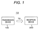
- Fig. 1 illustrates an exemplary configuration of a transmission and reception system 10 as the embodiment.
- the transmission and reception system 10 includes a transmission device 100 and a reception device 200.
- the transmission device 100 generates an MPEG-2 transport stream TS as a container, and transmits the MPEG-2 transport stream TS on a broadcast wave or in packets on the Internet.
- the transport stream TS includes a video stream provided by encoding video data for transmission.
- the video data for transmission is the video data of an LDR image provided by applying a predetermined level-mapping curve to the video data of an original HDR image that is the input video data.
- the range of levels of the video data for transmission is compressed from the range of levels of the input video data. However, the whole range of levels is not necessarily compressed evenly.
- a low-compression range and a high-compression range are generated. The width or position of the low-compression range also varies.
- the original HDR image namely, the input video data is in a first range of levels
- the image to be transmitted namely, the video data for transmission is in a second range of levels narrower than the first range of levels.
- Fig. 2(a) illustrates the levels of the original HDR image, in other words, illustrates exemplary distribution of levels of the input video data.
- the input video data is in a range of levels between zero and N% (N > 100).
- Fig. 2(b) illustrates the levels of the encoded and transmitted image, in other words, illustrates exemplary distribution of levels of the video data for transmission.
- the range from zero to J% of the input video data is a high-compression range.
- the range is converted into a range from zero to J'% of the video data for transmission with a level mapping process.
- the range from J to K% of the input video data is a low-compression range.
- the range is converted into a range from J' to K'% of the video data for transmission with the level mapping process.
- the range from K to N% of the input video data is a high-compression range.
- the range is converted into a range from K' to P% of the video data for transmission with the level mapping process.
- the low-compression range is a range of levels of lightness in which the original image is transmitted with minor quality loss due to the level mapping process.
- the high-compression range is a range of levels in which the levels of the original image are proactively compressed to predetermined levels for display in the level mapping process. Selectively compressing the range of levels as described above allows for appropriate display of the darkness and brightness of the image on a display device (monitor) that is not compatible with an HDR image.
- Fig. 3 illustrates exemplary HDR conversion characteristics, namely, exemplary level-mapping curves.
- a level-mapping curve (1) is an example in which the dark part of an image is finely expressed.
- the range of levels is divided into three ranges: a dark level range, a middle level range, and a bright level range.
- the dark level range is converted into a range with the largest number of levels
- the middle level range is converted into a range with the second largest number of levels
- the bright level range is converted into a range with a small number of levels.
- a level-mapping curve (2) is an example in which the part in the middle level range of the image is finely expressed.
- the middle level range of the three divided ranges is converted into a range with the largest number of levels
- the bright level range is converted into a range with the second largest number of levels
- the dark level range is converted into a range with a small number of levels.
- a level-mapping curve (3) is an example in which the parts in the three level ranges of brightness of the image are evenly expressed.
- Fig. 3 illustrates the three linked level-mapping curves. Note that, however, the number is not limited to three.
- the transmission device 100 transmits the video data for transmission together with the auxiliary information used to convert the levels of the video data on the receiving end. For example, the transmission device 100 inserts the level-mapping curve information and/or the electro-optical conversion characteristic information as the auxiliary information into a layer of the video stream.
- the level-mapping curve information includes, for example, the percentage term of the peak level of brightness on an uncompressed axis (see “Uw” in Fig. 3 ), the percentage terms of levels of mapping points in the range to the percentage term of the peak level on the uncompressed axis (see “U1 and U2" in Fig. 3 ), the percentage term of the peak level of brightness on a level-compressed axis (see “Vw” in Fig. 3 ), and the percentage terms of levels of mapping points in the range to the percentage term of the peak level on the level-compressed axis (see “V1 and V2" in Fig. 3 ).
- the electro-optical conversion characteristic information includes, for example, the type of the electro-optical conversion characteristic, or the value of a lookup table (LUT) indicating the electro-optical conversion characteristic.
- the reception device 200 receives the transport stream TS transmitted from the transmission device 100 on a broadcast wave or in packets on the Internet.
- the transport stream TS includes the video stream provided by encoding the video data for transmission.
- the reception device 200 provides the video data for display (video data for output), for example, by a process for decoding the video stream.
- the level-mapping curve information and/or the electro-optical conversion characteristic information are inserted as the auxiliary information in the layer of the video stream.
- the reception device 200 generates the video data of the HDR image to be replayed by reversely converting the video data for transmission in HDR reverse conversion that is opposite to the HDR conversion by the transmission device 100 in accordance with the level-mapping curve information.
- the range of levels of the video data of the HDR image to be replayed is a third range of levels wider than or equal to the second range of levels that is the range of levels of the video data for transmission.
- the highest level (peak level) of the video data of the HDR image to be replayed is limited, for example, to the highest level (peak level) of the video data of the original HDR image or the highest level (peak level) that the receiving function defines as the highest level to display.
- Fig. 4 (a) illustrates exemplary levels of the encoded and transmitted image, namely, exemplary level distribution of the video data for transmission.
- Fig. 4(b) illustrates exemplary distribution of levels of the video data of the HDR image provided by reversely converting the video data for transmission in conversion opposite to the HDR conversion on the transmitting end in accordance with the level-mapping curve information.
- the video data of the HDR image in this example is in a range of levels between zero and N% (N > 100).
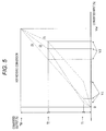
- Fig. 5 illustrates exemplary HDR reverse conversion characteristics in accordance with the level-mapping curve information.
- the HDR reverse conversion characteristics(1), (2), and (3) correspond to the level-mapping curves (1), (2), and (3) in Fig. 3 , respectively.
- the highest level of the video data of the HDR image to be replayed is determined as described below depending on the magnitude relationship between the highest level of the video data of the original HDR image (N%) and the highest level that the receiving function defines as the highest level to display (Q%).
- N% the highest level of the video data of the HDR image to be replayed
- P ⁇ N ⁇ Q the highest level of the video data of the HDR image to be replayed
- Fig. 4 (b) illustrates the distribution of levels of the video data of the HDR image to be replayed when the highest level of the video data of the HDR image to be replayed is N%.
- the range of levels of the video data for transmission from zero to J'% is converted into the range of levels of the HDR image to be replayed from zero to J% in the HDR reverse conversion.
- the range of levels of the video data for transmission from J' to K'% is converted into the range of the video data of the HDR image to be replayed from J to K% in the HDR reverse conversion.
- the range of levels of the video data for transmission from K' to P% is converted into the range of levels of the video data of the HDR image to be replayed from K to N% in the HDR reverse conversion.
- the high level value of the part in the video data of the HDR image to be replayed is provided by multiplying the high level value of the part in the video data for transmission by the ratio (N - K)/(P - K').
- Fig. 4 (c) illustrates the distribution of levels of the video data of the HDR image to be replayed when the highest level of the video data of the HDR image to be replayed is Q%.
- the range of levels of the video data for transmission from zero to J'% is converted into the range of levels of the video data of the HDR image to be replayed from zero to J% in the HDR reverse conversion.
- the range of levels of the input video data from J' to K'% is converted into the range of levels of the video data of the HDR image to be replayed from J to K% in the HDR reverse conversion.
- the range of levels of the input video data from K' to P% is converted into the range of levels of the video data of the HDR image to be replayed from K to Q% in the HDR reverse conversion.
- the high level value of the part in the video data of the HDR image to be replayed is provided by multiplying the high level value of the part in the video data for transmission by the ratio Q ⁇ K / P ⁇ K ⁇ .
- the reception device 200 generates the video data for display (video data for output) by converting the video data for transmission or the video data of the HDR image provided by reversely converting the video data for transmission in the HDR reverse conversion in accordance with the electro-optical conversion characteristic information in an electro-optical conversion process.
- Fig. 6 illustrates exemplary electro-optical conversion characteristics.
- a curve a indicates an exemplary electro-optical conversion characteristic used to display a part at low luminance with a high degree of accuracy.
- a curve b indicates an exemplary electro-optical conversion characteristic used to roughly display a part at extremely low luminance and display a part at another luminance with a high degree of accuracy.
- a curve c indicates an exemplary electro-optical conversion characteristic used to display an image while keeping a good balance between the part at high luminance and the part at low luminance in the image. Note that the opto-electronic conversion characteristic used in the transmission device 100 is usually opposite to the electro-optical conversion characteristic used in the reception device 200.
- Fig. 7 is an exemplary configuration of the transmission device 100.
- the transmission device 100 includes a control unit 101, a camera 102, an opto-electronic conversion unit 103, an HDR conversion unit 104, a video encoder 105, a system encoder 106, and a transmission unit 107.
- the control unit 101 includes a Central Processing Unit (CPU), and controls the operation of each unit in the transmission device 100 in accordance with the control program stored in a storage unit (not illustrated).
- CPU Central Processing Unit
- the camera 102 captures an image of an object and outputs the video data as a High Dynamic Range (HDR) image.
- the video data is in a range of levels from zero to 100%N, for example, from zero to 400%, or zero to 800%.
- the level of 100% corresponds to a value of white luminance of 100 cd/m2.
- the opto-electronic conversion unit 103 opto-electronically converts the video data provided from the camera 102 by applying a gamma curve to the video data.
- the HDR conversion unit 104 generates the video data for transmission of an LDR image in a compressed range of levels (see Figs. 2(a) and 2(b) ) by converting the opto-electronically converted video data of the HDR image by applying a predetermined level-mapping curve to the video data (see Fig. 3 ) in HDR conversion (level mapping).
- level-mapping curve used in this example, a predetermined level-mapping curve linked to a parameter indicating the brightness of the image is selected by an automatic operation or the user operation.
- the video encoder 105 provides encoded video data by encoding the video data for transmission generated with the HDR conversion unit 104, for example, in MPEG-4 AVC, MPEG-2 video, or high Efficiency Video Coding (HEVC).
- the video encoder 105 generates a video stream (video elementary stream) including the encoded video data, using a stream formatter provided on the downstream (not illustrated).
- the video encoder 105 inserts the auxiliary information into a layer of the video stream.
- the auxiliary information is used to convert the levels on the receiving end.
- the auxiliary information is the information about the level-mapping curve used in the HDR conversion unit 104, and the electro-optical conversion characteristic information.
- the electro-optical conversion characteristic indicated in the electro-optical conversion characteristic information depends on the characteristics of the image and is selected by automatic operation or the user operation.
- the system encoder 106 generates a transport stream TS including the video stream generated with the video encoder 105.
- the transmission unit 107 transmits the transport stream TS on a broadcast wave or in packets on the Internet to the reception device 200.
- the system encoder 106 can insert the identification information, which indicates that the auxiliary information (the information about the level-mapping curve and the electro-optical conversion characteristic information) used to convert the levels on the receiving end is inserted in the layer of the video stream, into a layer of the transport stream TS.
- the system encoder 106 inserts the identification information, for example, under a video elementary loop (Video ES loop) of a Program Map Table (PMT) included in the transport stream TS.
- PMT Program Map Table
- the operation of the transmission device 100 illustrated in Fig. 7 will briefly be described.
- the camera 102 captures an image and provides the video data of the HDR image.
- the opto-electronic conversion unit 103 opto-electronically converts the video data of the HDR image by applying the gamma curve to the video data of the HDR image, and transmits the opto-electronically converted video data to the HDR conversion unit 104.
- the HDR conversion unit 104 generates the video data for transmission of an LDR image by converting the opto-electronically converted video data of the HDR image by applying a predetermined level-mapping curve to the opto-electronically converted video data of the HDR image in HDR conversion (see Figs. 2(a) and (b) ).
- the video data for transmission of the LDR image generated with the HDR conversion unit 104 is provided to the video encoder 105.
- the video encoder 105 generates a video stream (video elementary stream) including encoded video data by encoding the video data for transmission of the LDR image, for example, in HEVC. Meanwhile, the video encoder 105 inserts the auxiliary information (the information about the level-mapping curve and the electro-optical conversion characteristic information) used to convert the levels on the receiving end into a layer of the video stream.
- the video stream generated with the video encoder 105 is provided to the system encoder 106.
- the system encoder 106 generates an MPEG-2 transport stream TS including the video stream.
- the transmission unit 107 transmits the transport stream TS on a broadcast wave or in packets on the Internet to the reception device 200.
- the auxiliary information (the information about the level-mapping curve and the electro-optical conversion characteristic information) is inserted in the layer of the video stream.
- the auxiliary information is inserted as an HDR mapping SEI message (HDR_mapping SEI message) in the part of "SEIs" in the access unit (AU).
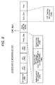
- Fig. 8 illustrates the access unit at the beginning of a Group Of Pictures (GOP) when HEVC is used as the encoding scheme.
- GOP Group Of Pictures
- an SEI message group "Prefix_SEIs” used for decoding is placed before “slices” in which pixel data is encoded
- an SEI message group "Suffix_SEIs” used for display is placed after the "slices”.
- the HDR mapping SEI message is placed as the SEI message group "Suffix_SEIs”.
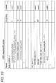
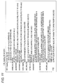
- Fig. 9 and Fig. 10 illustrate an exemplary structure (Syntax) of the "HDRmapping SEI message”.
- Fig. 11 illustrates the contents of the main information in the exemplary structure (Semantics).
- the "HDR_mapping_refresh_flag” is the one-bit flag information. The "1" indicates that the previous message about HRD mapping is refreshed. The “0" indicates that the previous message is not refreshed.
- the eight-bit field of "coded_data_bits” indicates the bit length of encoded data with values.
- the 16-bit field of "uncompressed_peak_level_percentage” indicates the percentage term of the highest level of the source image data (the value relative to 100 cd/m2), for example, the value of "Uw” in Fig. 3 .
- the 16-bit field of "compressed_peak_level_percentage” indicates the percentage term of the highest level of the encoded image data (the value relative to 100 cd/m2), for example, the value of "Vw” in Fig. 3 .
- the "level_mapping_flag” is the one-bit flag information indicating whether the parameters for level mapping exist.
- the “1” indicates that the parameters for level mapping exist.
- the “eotf_linked_flag” is the one-bit flag information indicating whether to use the conversion curve of the electro-optical conversion (EOTF) in order to perform the level mapping.
- the “1” indicates that the conversion curve of the electro-optical conversion (EOTF) is used to perform the level mapping.
- the eight-bit field of "number_of_mapping_periods” indicates the number of linked level-mapping curves. For example, the number of linked level-mapping curves is three in Fig. 3 .
- the 16-bit field of "compressed_mapping_point” indicates a point where the level-mapping curve varies on the level-compressed axis with the percentage term on the assumption that the "compressed_peak_level_percentage” is 100%. For example, the point is the value of "V1, V2, or Vw” in Fig. 3 .
- the 16-bit field of "uncompressed_mapping_point” indicates a point where the level-mapping curve varies on the level-uncompressed axis with the percentage term on the assumption that the "uncompressed_peak_level_percentage” is 100%.
- the point is the value of "U1, U2, or Uw” in Fig. 3 .
- the four-bit field of "eotf_table_type_main” indicates the main type of the conversion curve of the electro-optical conversion (EOTF), and indicates that a conversion curve of the electro-optical conversion (EOTF) specialized for a specific image is transmitted when the "eotf_linked_flag" is "0xF”.
- the 16-bit field of "tbl [j]” indicates the output value from the input value "j" on the transmitted conversion curve of the electro-optical conversion (EOTF).
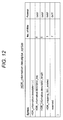
- Fig. 12 illustrates an exemplary structure (Syntax) of an HDR information descriptor (HDR_information descriptor) as the identification information.
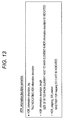
- Fig. 13 illustrates the contents of the main information in the exemplary structure (Semantics).
- the eight-bit field of "HDR_information descriptor tag” indicates the type of the descriptor, and indicates that the type is the HDR information descriptor in this example.
- the eight-bit field of "HDR_ information descriptor length” indicates the length (size) of the descriptor, and indicates the number of subsequent bytes as the length of the descriptor.
- the one-bit field of "HDR_mapping_SEI_existed" is the flag information indicating whether the HDR mapping SEI information exists in a video layer (a layer of the video stream). The "1" indicates that the HDR mapping SEI information exists while the "0” indicates that the HDR mapping SEI information does not exist.
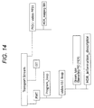
- Fig. 14 illustrates an exemplary structure of the transport stream TS.
- the transport stream TS includes a PES packet "PID1: video PES1" of the video elementary stream.
- the HDR mapping SEI message (HDR_mapping SEI message) is inserted in the video elementary stream.
- the transport stream TS further includes a Program Map Table (PMT) as the Program Specific Information (PSI).
- PSI indicates which program each elementary stream included in the transport stream belongs to.
- the transport stream TS further includes an Event Information Table (EIT) as the Serviced Information (SI) used to manage each event (program).
- EIT Event Information Table
- An elementary loop including the information related to each elementary stream exists in the PMT.
- a video elementary loop (Video ES loop) exists.
- the information for example, about the type of the stream and a packet identifier (PID) is placed in the video elementary loop, corresponding to each video elementary stream, and the descriptor indicating the information related to the video elementary stream is also placed.
- PID packet identifier
- the HDR information descriptor (HDR_information descriptor) is placed under the video elementary loop (Video ES loop) in the PMT.
- the descriptor indicates whether the HDR mapping SEI information is inserted in the video stream as described above.
- the reception device 200 includes a control unit 201, a reception unit 202, a system decoder 203, a video decoder 204, an HDR reverse conversion unit 205, an electro-optical conversion unit 206, and a display unit 207.
- the control unit 201 includes a Central Processing Unit (CPU), and controls each unit in the reception device 200 in accordance with the control program stored in a storage unit (not illustrated).
- CPU Central Processing Unit
- the reception unit 202 receives the transport stream TS transmitted from the transmission device 100 on a broadcast wave or in packets on the Internet.
- the system decoder 203 extracts a video stream (elementary stream) from the transport stream TS.
- the identification information which indicates that the auxiliary information (the information about the level-mapping curve and the electro-optical conversion characteristic information) is inserted, is inserted in the layer of the transport stream TS, the system decoder 203 extracts and transmits the identification information to the control unit 201.
- the control unit 201 can recognize that the auxiliary information (the information about the level-mapping curve and the electro-optical conversion characteristic information), namely, the HDR mapping SEI message (HDR_mapping SEI message) is inserted in the video stream. Based on the recognition, the control unit 201 can control, for example, the video decoder 204 to actively acquire the HDR mapping SEI message.
- the auxiliary information the information about the level-mapping curve and the electro-optical conversion characteristic information
- HDR mapping SEI message HDR_mapping SEI message
- the video decoder 204 provides the baseband video data (video data for transmission) by decoding the video stream extracted by the system decoder 203 in a decoding process.
- the video decoder 204 extracts the SEI messages inserted in the video stream and transmits the SEI messages to the control unit 201.
- the SEI messages include the HDRmapping SEI message (HDR_mapping SEI message).
- the control unit 201 controls the decoding process or a displaying process in accordance with the SEI messages.
- the HDR reverse conversion unit 205 generates the video data of the HDR image to be replayed in an extended range of levels by reversely converting the video data for transmission provided by the video decoder 204 in accordance with the level-mapping curve information included in the HDR mapping SEI message in HDR reverse conversion (see Figs. 4 (a) to 4(c) ).
- the HDR reverse conversion for example, when the image input to the HDR reverse conversion unit 205 is displayed with 10 bits or lower in this example, the image output from the HDR reverse conversion unit 205 is displayed with 12 bits or more.
- the HDR reverse conversion unit 205 determines the highest level of the video data of the HDR image to be replayed, depending on the magnitude relationship between the highest level of the video data of the original HDR image (N%) and the highest level that the receiving function defines as the highest level to display (Q%). In other words, when Q ⁇ N holds, the highest level of the video data of the HDR image to be replayed is Q%. When N ⁇ Q holds, the highest level of the video data of the HDR image to be replayed is N%.
- the HDR reverse conversion unit 205 outputs the video data for transmission of the LDR image input from the video decoder 204 without change.
- the electro-optical conversion unit 206 electro-optically converts the video data output from the HDR reverse conversion unit 205 (the video data of the HDR image to be replayed or the video data for transmission of the LDR image), in other words, maps the levels of the video data in accordance with the electro-optical conversion characteristic information included in the HDR mapping SEI message.
- the electro-optical conversion unit 206 uses the conversion curve of which type is indicated in the HDR mapping SEI message or the conversion curve transmitted in the HDR mapping SEI message as the conversion curve of the electro-optical conversion (EOTF). Note that, when the video data is transmitted in another method, the auxiliary information can be recognized in accordance with the signaling information included in the parameter set of the video (SPS).
- the information indicating the type of the conversion curve of the electro-optical conversion (EOTF) included in the HDR mapping SEI message is "eotf_table_type_main", and the “eotf_table_type_main” indicates the main type of the conversion curve (see Fig. 10 ).
- the main type indicated in the "eotf_table_type_main” is subdivided into sub types indicated in the "eotf_table_type_sub".
- the electro-optical conversion unit 206 uses the conversion curve of the electro-optical conversion (EOTF) determined in accordance with both of the main type and the sub type.
- Fig. 16 illustrates exemplary combinations of the main type indicated in the information "eotf_table_type_main” and the sub type indicated in the information “eotf_table_type_sub”.
- main type indicated in the information "eotf_table_type_main” there are three main types “1", “2”, and “3”, and there are three sub types "1", "2”, and "3".
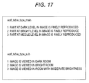
- each of the main and sub types indicates the characteristic of the conversion curve, for example, as illustrated in Fig. 17 .
- the main type "1" indicates the conversion curve suitable for finely reproducing the part at a dark level in the image.
- the main type “2” indicates the conversion curve suitable for roughly reproducing the part with extremely low luminance and clearly reproducing with another luminance in the image.
- the main type “3” indicates the conversion curve suitable for finely reproducing the part at a middle level in the image.
- the sub type "1” indicates the conversion curve suitable for viewing the image in a dark room.
- the sub type “2” indicates the conversion curve suitable for viewing the image in a bright room.
- the sub type “3” indicates the conversion curve suitable for viewing the image in a room with moderate brightness. Note that the number of the main or sub types is not limited to three.
- the characteristic of each type is not limited to the content illustrated in Fig. 17 .
- the information "eotf_table_type_main” is provided in the HDR mapping SEI message from the transmission device 100 as described above.
- the information “eotf_table_type sub” is provided in the reception device 200 in accordance with the environments in which the image is viewed.
- the sub type indicated in the "eotf_table_type_sub” is determined in accordance with the output from a brightness sensor or the user operation. This selects the sub type among the sub types included in the main type, and thus selects the electro-optical conversion characteristic to be used in the electro-optical conversion unit 206.
- Fig. 18 schematically illustrates the cooperation of the HDR reverse conversion and electro-optical conversion performed in the reception device 200.
- the received image is changed into an image to be displayed after being converted with the HDR reverse conversion and the electro-optical conversion.
- the conversion characteristic of the HDR reverse conversion corresponds to the level-mapping curve used in the HDR conversion on the transmitting end. For example, a predetermined level-mapping curve linked to the parameters indicating the brightness of the image is used on the transmitting end as described above.
- the electro-optical conversion characteristic is designated with the main type indicated in the information "eotf_table_type_main” and the sub type indicated in the information "eotf_table_type_sub”.
- the main type is set on the transmitting end, depending on the characteristics of the image.
- the sub type is set on the receiving end in accordance with the environments in which the image is viewed.
- the electro-optical conversion unit 206 performs the electro-optical conversion by using a conventional inverse gamma characteristic.
- the display unit 207 displays the image using the video data for display output from the electro-optical conversion unit 206.
- the display unit 207 includes, for example, a liquid crystal display panel, and an organic EL display panel.
- the reception unit 202 receives the transport stream TS transmitted on a broadcast wave or in packets on the Internet from the transmission device 100.
- the transport stream TS is provided to the system decoder 203.
- the system decoder 203 extracts a video stream (elementary stream) from the transport stream TS.
- the video stream extracted by the system decoder 203 is provided to the video decoder 204.
- the video decoder 204 provides the baseband video data (video data for transmission) by decoding the video stream in a decoding process. Meanwhile, the video decoder 204 extracts the SEI messages included in the video stream and transmits the SEI messages to the control unit 201.
- the SEI messages include the HDRmapping SEI message (HDR_mapping SEI message).
- the control unit 201 controls the decoding process or a displaying process in accordance with the SEI messages.
- the video data for transmission of the LDR image provided by the video decoder 204 is provided to the HDR reverse conversion unit 205.
- the HDR reverse conversion unit 205 generates the video data of the HDR image to be replayed in an extended range of levels by reversely converting the video data for transmission of the LDR image provided by the video decoder 204 in accordance with the level-mapping curve information included in the HDR mapping SEI message in HDR reverse conversion. Note that, when the HDR mapping SEI message does not include the level-mapping curve information, the HDR reverse conversion unit 205 outputs the video data for transmission of the LDR image input from the video decoder 204 without change.
- the video data provided by the HDR reverse conversion unit 205 is provided to the electro-optical conversion unit 206.
- the electro-optical conversion unit 206 generates the video data for display by electro-optically converting the video data output from the HDR reverse conversion unit 205 (the video data of the HDR image to be replayed or the video data for transmission of the LDR image) in electro-optical conversion, in other words, mapping the levels of the video data in level mapping.
- the electro-optical conversion unit 206 uses the conversion curve of which type is indicated in the HDR mapping SEI message or the conversion curve transmitted in the HDR mapping SEI message as the conversion curve of the electro-optical conversion (EOTF). Note that, when the HDR mapping SEI message does not include the electro-optical conversion characteristic information, the electro-optical conversion is performed, for example, with a conventional inverse gamma characteristic.
- the video data for display provided by the electro-optical conversion unit 206 is provided to the display unit 207.
- the display unit 207 displays the image of the video data for display.
- Fig. 19 illustrates an exemplary flow of a process that the reception device 200 performs.
- the reception device 200 starts the process in step ST1. Subsequently, the reception device 200 receives the video stream in step ST2. Then, the reception device 200 determines whether to read the HDRmapping SEI message in step ST3. The reception device 200 determines to read the HDR mapping SEI message when the video stream includes the HDR mapping SEI message.
- the reception device 200 When determining to read the HDR mapping SEI message, the reception device 200 recognizes the encoded bits and the percentage term of the peak level of the encoded image data in step ST4. Next, the reception device 200 recognizes the percentage term of the peak level of the original image in step ST5.
- the reception device 200 provides the video data of the HDR image to be replayed by performing HDR reverse conversion in accordance with the level-mapping curve information included in the HDR mapping SEI message in step ST6.
- the reception device 200 provides the video data for display by recognizing the type of the conversion curve of the electro-optical conversion (EOTF) or receiving the conversion curve of the electro-optical conversion (EOTF) specialized for a specific image, and performing the electro-optical conversion in step ST7.
- the reception device 200 completes the process in step ST8 after the process in step ST7.
- the reception device 200 When determining not to read the HDR mapping SEI message in step ST3, the reception device 200 provides the video data for display by electro-optically converting the video data of the input LDR image with a conventional inverse gamma correction in step ST9 in the electro-optical conversion. The reception device 200 completes the process in step ST8 after the process in step ST9.
- the transmission device 100 In the transmission and reception system 10 illustrated in Fig. 1 , the transmission device 100 generates the video data for transmission of an LDR image by compressing the range of levels of the video data of the original HDR image with a specific level-mapping curve, and then transmits the video data for transmission of the LDR image as described above.
- a characteristic appropriate to the contents of the image as the predetermined level-mapping curve allows for good display of the LDR image from the video data for transmission on an LDR monitor.
- the transmission device 100 further transmits the auxiliary information used to convert the levels on the receiving end together with the video data for transmission. This enables, for example, the receiving end to appropriately convert the levels of the video data for transmission in accordance with the auxiliary information, and thus to display the image in good condition.
- the transmission device 100 transmits the electro-optical conversion characteristic information including information about a plurality of electro-optical conversion characteristics, namely, the information "eotf_table_type_main". This enables the receiving end to automatically or manually select the electro-optical conversion characteristic suitable for the environments in which the image is viewed among the electro-optical conversion characteristics and use the selected electro-optical conversion characteristic, and thus to display a high-quality image suitable for the brightness of the environment on the monitor.
- the HDR reverse conversion unit 205 performs the HDR reverse conversion and the electro-optical conversion unit 206 performs the electro-optical conversion in the reception device 200 has been described in the embodiment. Note that, however, for example, reflecting the HDR reverse conversion characteristic on the electro-optical conversion characteristic enables the electro-optical conversion unit 206 to solely simultaneously perform the HDR reverse conversion and the electro-optical conversion.
- Fig. 20(a) illustrates a level mapping characteristic (HDR reverse conversion characteristic).
- the level mapping characteristic is the information used to convert an LDR image into an HDR image with the correspondence between the relative levels on the compressed-level axis and the relative levels on the uncompressed-level axis.
- Fig. 20(b) illustrates electro-optical conversion characteristics.
- a curve LC indicates a conventional electro-optical conversion characteristic
- a curve HDC indicates the electro-optical conversion characteristic provided by reflecting the HDR reverse conversion characteristic on the conventional electro-optical conversion characteristic.
- a line NTr indicates a straight line extending between the highest and lowest levels in comparison with the curves of the electro-optical conversion.
- a curve LC -1 indicates the inverse characteristic, and the curve LC -1 and the curve LC are symmetric with respect to the line NTr.
- the curve LC -1 is used to transfer the characteristic between the vertical axis and horizontal axis in Fig. 20(b) .
- the vertical axis and horizontal axis of the HDR reverse conversion characteristic are normalized with the ratio of the highest relative level of the vertical axis to the highest relative level of the horizontal axis (the ratio of the highest values of the dynamic ranges).
- the ratio of the range of the vertical axis to the range of the horizontal axis is N(%) to P(%).
- the ratio of the vertical axis in Fig. 20(a) to the horizontal axis in Fig. 20(b) is one to one.
- the values V1, V2, and Vw on the horizontal axis in Fig. 20(b) are identical to those on the horizontal axis in Fig. 20(a) .
- the values T1, T2, and Tw on the vertical axis in Fig. 20 (a) are placed as the values T1', T2', and Tw' on the horizontal axis in Fig. 20(b) .
- the input V1 corresponds to the output T1.
- the point plotted in Fig. 20(b) which satisfies the characteristic illustrated in Fig. 20 (a) and the characteristic of the curve LC in Fig. 20 (b) , is the vertical-axis coordinate of the point b1 with respect to the V1 on the horizontal axis in Fig. 20 (b) .
- the value of the vertical-axis coordinate of the point b1 is the value of the vertical-axis coordinate of a point b11 of the V1.
- the value of the vertical-axis coordinate with respect to the V2 on the horizontal axis in Fig. 20(b) is the value of the vertical-axis coordinate of a point b2 plotted on the curve LC with respect to the T2'.
- the value of the vertical-axis coordinate with respect to the V2 is the value of the vertical-axis coordinate of a point b21.
- the value of the vertical-axis coordinate with respect to the Vw is the point that is the vertical-axis coordinate of the point b3 plotted on the curve LC with respect to the Tw', namely, the vertical-axis coordinate of the plotted point b31 with respect to the Vw.
- the curve HDC has a characteristic simultaneously satisfying the characteristic illustrated in Fig. 20(a) and the characteristic indicated by the curve LC in Fig. 20 (b) .
- This characteristic is the electro-optical conversion characteristic solely satisfying the HDR reverse conversion and the electro-optical conversion.
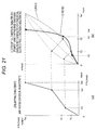
- Fig. 21 (a) illustrates the level mapping characteristic (HDR reverse conversion characteristic) corresponding to the line (2) in Fig. 5 .
- Fig. 21 (b) illustrates the electro-optical conversion characteristics.
- a curve LC indicates a conventional electro-optical conversion characteristic
- an curve HDC indicates the electro-optical conversion characteristic provided by reflecting the HDR reverse conversion characteristic illustrated in Fig. 21(a) on the conventional electro-optical conversion characteristic. Note that the curve HDC is found in the same manner as described with reference to Figs. 20(a) and 20(b) .
- the opto-electronic conversion unit 103 performs the opto-electronic conversion and the HDR conversion unit 104 performs the HDR conversion in the transmission device 200 has been described in the embodiment. However, reflecting the HDR conversion characteristic on the opto-electronic conversion characteristic enables the opto-electronic conversion unit 103 to solely simultaneously perform the opto-electronic conversion and the HDR conversion.
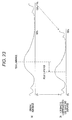
- Fig. 22 (b) illustrates the level mapping characteristic (HDR conversion characteristic) corresponding to the line (1) in Fig. 3 .
- Fig. 22(a) illustrates a conventional opto-electronic conversion characteristic, and the HDR opto-electronic conversion characteristic provided by reflecting the HDR conversion characteristic illustrated in Fig. 22(b) on the conventional opto-electronic conversion characteristic. Note that, although omitting the detailed description, the HDR opto-electronic conversion characteristic is found in the same manner as the manner to find the electro-optical conversion characteristic (curve HDC) on which the HDR reverse conversion characteristic is reflected.
- curve HDC electro-optical conversion characteristic
- the HDR conversion unit 104 in the transmission device 100 converts an HDR image into an LDR image and the transmission device 100 transmits the parameters for the HDR conversion (the level-mapping curve information) together with the LDR image, and the HDR reverse conversion unit 205 converts the LDR image into an HDR image in accordance with the transmitted parameters and displays the HDR image in the reception device 200 has been described in the embodiment.
- the transmission device 100 can transmit the parameters used to convert an HDR image into an LDR image together with the HDR image, without converting the HDR image into the LDR image with the HDR conversion unit 104 in the transmission device 100, and the HDR reverse conversion unit 205 can convert the received HDR image into an LDR image in accordance with the parameters and display the LDR image in the reception device 200.
- the electro-optical conversion characteristic of the receiver includes a characteristic to convert HDR into the LDR and the conventional electro-optical conversion characteristic.
- the present invention can also be configured as follows.
- a main aspect of the present invention is to enable the receiving end to display an LDR image in good condition by transmitting the video data for transmission of the LDR image generated by applying a specific level-mapping curve to thevideo data of the original HDR image (see Figs. 2(a) and 2(b) , and Fig. 7 ).
- Another main aspect of the present invention is to enable the receiving end to appropriately convert the levels in the level converting process and thus to display an image in good condition by transmitting the auxiliary information used to convert the levels on the receiving end together with the video data for transmission (see Figs. 4 (a) to 4(c) , and Fig. 15 ).
Landscapes
- Engineering & Computer Science (AREA)
- Multimedia (AREA)
- Signal Processing (AREA)
- Two-Way Televisions, Distribution Of Moving Picture Or The Like (AREA)
- Picture Signal Circuits (AREA)
- Compression Or Coding Systems Of Tv Signals (AREA)
- Television Systems (AREA)
- Studio Devices (AREA)
- Controls And Circuits For Display Device (AREA)
Applications Claiming Priority (2)
| Application Number | Priority Date | Filing Date | Title |
|---|---|---|---|
| JP2014011890 | 2014-01-24 | ||
| PCT/JP2015/050686 WO2015111467A1 (fr) | 2014-01-24 | 2015-01-13 | Dispositif de transmission, procédé de transmission, dispositif de réception et procédé de réception |
Publications (2)
| Publication Number | Publication Date |
|---|---|
| EP3099062A1 true EP3099062A1 (fr) | 2016-11-30 |
| EP3099062A4 EP3099062A4 (fr) | 2017-09-20 |
Family
ID=53681274
Family Applications (1)
| Application Number | Title | Priority Date | Filing Date |
|---|---|---|---|
| EP15740130.8A Ceased EP3099062A4 (fr) | 2014-01-24 | 2015-01-13 | Dispositif de transmission, procédé de transmission, dispositif de réception et procédé de réception |
Country Status (9)
| Country | Link |
|---|---|
| US (2) | US10701403B2 (fr) |
| EP (1) | EP3099062A4 (fr) |
| JP (1) | JP6686438B2 (fr) |
| KR (1) | KR102293193B1 (fr) |
| CN (1) | CN105917646B (fr) |
| CA (1) | CA2936313C (fr) |
| MX (1) | MX367832B (fr) |
| RU (1) | RU2667083C1 (fr) |
| WO (1) | WO2015111467A1 (fr) |
Cited By (1)
| Publication number | Priority date | Publication date | Assignee | Title |
|---|---|---|---|---|
| EP3352163A4 (fr) * | 2015-09-14 | 2018-09-26 | Panasonic Intellectual Property Management Co., Ltd. | Procédé de réception vidéo, procédé de transmission vidéo, dispositif de réception vidéo et dispositif de transmission vidéo |
Families Citing this family (16)
| Publication number | Priority date | Publication date | Assignee | Title |
|---|---|---|---|---|
| CN106063243B (zh) * | 2014-02-25 | 2020-07-21 | 交互数字Vc控股公司 | 生成关于图像/视频信号的方法、携带特定信息数据的比特流以及获得该特定信息的方法 |
| MX363812B (es) * | 2014-06-10 | 2019-04-04 | Panasonic Ip Man Co Ltd | Método de conversión y aparato de conversión. |
| CN107950031B (zh) * | 2015-09-11 | 2021-02-19 | 松下知识产权经营株式会社 | 影像接收方法以及影像接收装置 |
| JP6986670B2 (ja) | 2015-09-11 | 2021-12-22 | パナソニックIpマネジメント株式会社 | 映像受信方法及び映像受信装置 |
| CN112954353B (zh) * | 2015-09-14 | 2024-09-13 | 松下知识产权经营株式会社 | 解码装置和解码方法 |
| EP3350985B1 (fr) * | 2015-09-18 | 2022-04-20 | Teledyne Flir, LLC | Transfert d'images thermiques radiométriques de plage dynamique élevée sur une interface à faible débit binaire |
| JP6645871B2 (ja) | 2015-09-30 | 2020-02-14 | マクセル株式会社 | 放送システム |
| JP6616212B2 (ja) | 2015-09-28 | 2019-12-04 | マクセル株式会社 | 表示制御方法 |
| JP6441247B2 (ja) * | 2015-10-01 | 2018-12-19 | マクセル株式会社 | 表示制御方法 |
| WO2017061071A1 (fr) * | 2015-10-07 | 2017-04-13 | パナソニックIpマネジメント株式会社 | Procédé d'émission vidéo, procédé de réception de vidéo, dispositif d'émission vidéo et dispositif de réception de vidéo |
| JP6830190B2 (ja) * | 2015-10-07 | 2021-02-17 | パナソニックIpマネジメント株式会社 | 映像送信方法、映像受信方法、映像送信装置及び映像受信装置 |
| JP6132006B1 (ja) * | 2015-12-02 | 2017-05-24 | 日本電気株式会社 | 映像符号化装置、映像システム、映像符号化方法、及び映像符号化プログラム |
| WO2018085447A1 (fr) * | 2016-11-04 | 2018-05-11 | Flir Systems, Inc. | Compression de plage dynamique pour vidéo thermique |
| JP6241558B2 (ja) * | 2017-02-03 | 2017-12-06 | 日本電気株式会社 | 映像符号化装置、映像システム、映像符号化方法、及び映像符号化プログラム |
| CN107277399B (zh) * | 2017-06-09 | 2020-10-20 | 深圳Tcl新技术有限公司 | 电视终端及hdr图像转为sdr的方法和计算机可读存储介质 |
| JP6241565B2 (ja) * | 2017-08-07 | 2017-12-06 | 日本電気株式会社 | 映像符号化装置、映像システム、映像符号化方法、及び映像符号化プログラム |
Family Cites Families (26)
| Publication number | Priority date | Publication date | Assignee | Title |
|---|---|---|---|---|
| JPH05130413A (ja) * | 1991-10-31 | 1993-05-25 | Fujitsu Ltd | 画像データの符号化装置と復号装置および符号化方法と復号方法 |
| JP3144099B2 (ja) * | 1992-11-20 | 2001-03-07 | ソニー株式会社 | 適応ダイナミックレンジ符号化又は復号化装置 |
| US6560285B1 (en) | 1998-03-30 | 2003-05-06 | Sarnoff Corporation | Region-based information compaction as for digital images |
| JP3926947B2 (ja) | 1999-06-22 | 2007-06-06 | 富士フイルム株式会社 | 画像データ形成装置および画像データ処理方法 |
| US8194997B2 (en) * | 2006-03-24 | 2012-06-05 | Sharp Laboratories Of America, Inc. | Methods and systems for tone mapping messaging |
| US8135230B2 (en) * | 2007-07-30 | 2012-03-13 | Dolby Laboratories Licensing Corporation | Enhancing dynamic ranges of images |
| WO2010021705A1 (fr) * | 2008-08-22 | 2010-02-25 | Thomson Licensing | Procédé et système de fourniture de contenu |
| JP2011010108A (ja) | 2009-06-26 | 2011-01-13 | Seiko Epson Corp | 撮像制御装置、撮像装置及び撮像制御方法 |
| US9754629B2 (en) * | 2010-03-03 | 2017-09-05 | Koninklijke Philips N.V. | Methods and apparatuses for processing or defining luminance/color regimes |
| US9300938B2 (en) * | 2010-07-22 | 2016-03-29 | Dolby Laboratories Licensing Corporation | Systems, apparatus and methods for mapping between video ranges of image data and display |
| ES2974956T3 (es) | 2011-05-10 | 2024-07-02 | Koninklijke Philips Nv | Generación y procesamiento de señales de imágenes de alto rango dinámico |
| US9451292B2 (en) * | 2011-09-15 | 2016-09-20 | Dolby Laboratories Licensing Corporation | Method and system for backward compatible, extended dynamic range encoding of video |
| EP2745290A1 (fr) * | 2011-09-27 | 2014-06-25 | Koninklijke Philips N.V. | Appareil et procédé de transformation de gamme dynamique d'images |
| US9129445B2 (en) * | 2012-03-14 | 2015-09-08 | Dolby Laboratories Licensing Corporation | Efficient tone-mapping of high-bit-depth video to low-bit-depth display |
| MX350910B (es) * | 2013-02-21 | 2017-09-25 | Koninklijke Philips Nv | Métodos y dispositivos de codificación y decodificación de imágenes mejoradas de alto rango dinámico (hdr). |
| RU2657473C2 (ru) | 2013-04-30 | 2018-06-14 | Сони Корпорейшн | Устройство передачи, способ передачи, устройство приема и способ приема |
| CN103391435A (zh) * | 2013-07-02 | 2013-11-13 | 广东工业大学 | 一种兼容ldr的hdr图像编码方法及其解码方法 |
| US9712781B2 (en) * | 2013-09-06 | 2017-07-18 | Lg Electronics Inc. | Method and apparatus for transmitting and receiving ultra-high definition broadcasting signal for high dynamic range representation in digital broadcasting system |
| JP2016541140A (ja) | 2013-11-13 | 2016-12-28 | エルジー エレクトロニクス インコーポレイティド | Hdr放送サービスの提供のための放送信号送受信方法及び装置 |
| ES2825699T3 (es) * | 2014-12-11 | 2021-05-17 | Koninklijke Philips Nv | Optimización e imágenes de alto rango dinámico para pantallas particulares |
| EP3399497A1 (fr) * | 2017-05-05 | 2018-11-07 | Koninklijke Philips N.V. | Optimisation de saturation d'image décodée à plage dynamique élevée |
| EP3416363A1 (fr) * | 2017-06-13 | 2018-12-19 | Koninklijke Philips N.V. | Mappage de gamut pour le (dé)codage hdr |
| EP3525463A1 (fr) * | 2018-02-13 | 2019-08-14 | Koninklijke Philips N.V. | Système de manipulation de multiples formats vidéo hdr |
| GB2616980B (en) * | 2018-10-09 | 2023-12-13 | V Nova Int Ltd | Signal element coding format compatibility within a hierarchical coding scheme using multiple resolutions |
| US11128809B2 (en) * | 2019-02-15 | 2021-09-21 | Samsung Electronics Co., Ltd. | System and method for compositing high dynamic range images |
| US11533512B2 (en) * | 2020-04-10 | 2022-12-20 | Qualcomm Incorporated | Dynamic range adjustment parameter signaling and enablement of variable bit depth support |
-
2015
- 2015-01-13 MX MX2016009262A patent/MX367832B/es active IP Right Grant
- 2015-01-13 WO PCT/JP2015/050686 patent/WO2015111467A1/fr active Application Filing
- 2015-01-13 CN CN201580004856.9A patent/CN105917646B/zh active Active
- 2015-01-13 EP EP15740130.8A patent/EP3099062A4/fr not_active Ceased
- 2015-01-13 CA CA2936313A patent/CA2936313C/fr active Active
- 2015-01-13 KR KR1020167018843A patent/KR102293193B1/ko active IP Right Grant
- 2015-01-13 RU RU2016128922A patent/RU2667083C1/ru active
- 2015-01-13 US US15/036,996 patent/US10701403B2/en active Active
- 2015-01-13 JP JP2015558805A patent/JP6686438B2/ja active Active
-
2020
- 2020-05-27 US US16/884,668 patent/US11405656B2/en active Active
Cited By (2)
| Publication number | Priority date | Publication date | Assignee | Title |
|---|---|---|---|---|
| EP3352163A4 (fr) * | 2015-09-14 | 2018-09-26 | Panasonic Intellectual Property Management Co., Ltd. | Procédé de réception vidéo, procédé de transmission vidéo, dispositif de réception vidéo et dispositif de transmission vidéo |
| EP3700211A1 (fr) * | 2015-09-14 | 2020-08-26 | Panasonic Intellectual Property Management Co., Ltd. | Procédé de réception vidéo, procédé de transmission vidéo, dispositif de réception vidéo et dispositif de transmission vidéo |
Also Published As
| Publication number | Publication date |
|---|---|
| US20160309201A1 (en) | 2016-10-20 |
| EP3099062A4 (fr) | 2017-09-20 |
| CN105917646A (zh) | 2016-08-31 |
| MX2016009262A (es) | 2016-09-29 |
| JPWO2015111467A1 (ja) | 2017-03-23 |
| RU2667083C1 (ru) | 2018-09-14 |
| KR20160113114A (ko) | 2016-09-28 |
| MX367832B (es) | 2019-09-09 |
| KR102293193B1 (ko) | 2021-08-25 |
| US10701403B2 (en) | 2020-06-30 |
| CA2936313C (fr) | 2022-07-19 |
| US20200329259A1 (en) | 2020-10-15 |
| US11405656B2 (en) | 2022-08-02 |
| CA2936313A1 (fr) | 2015-07-30 |
| WO2015111467A1 (fr) | 2015-07-30 |
| CN105917646B (zh) | 2021-10-08 |
| JP6686438B2 (ja) | 2020-04-22 |
Similar Documents
| Publication | Publication Date | Title |
|---|---|---|
| US11405656B2 (en) | Transmission device, transmission method, reception device, and reception method | |
| JP7087028B2 (ja) | 受信装置、受信方法および表示装置 | |
| US11627367B2 (en) | Transmitting device, transmitting method, receiving device, and receiving method | |
| CN107787581B (zh) | 用于描述标定照明条件的元数据的方法和装置 | |
| RU2696216C2 (ru) | Передающее устройство, способ передачи, приемное устройство и способ приема | |
| JP7053722B2 (ja) | ビットストリーム内で、ldrピクチャのピクチャ/ビデオ・フォーマットと、このldrピクチャおよびイルミネーション・ピクチャから取得された復号済みのhdrピクチャのピクチャ/ビデオ・フォーマットとをシグナリングする方法および装置 | |
| KR20180081091A (ko) | 기본 스트림들로부터 디코딩된 비디오 콘텐츠를 디스플레이의 특성들에 적응시키기 위한 방법 및 디바이스 | |
| EP3051486A1 (fr) | Procédé et appareil de codage et de décodage de vidéos à plage dynamique élevée | |
| US11895309B2 (en) | Transmitting apparatus, transmitting method, receiving apparatus, and receiving method | |
| US10397642B2 (en) | Transmission device, transmission method, and reception device | |
| US11948519B2 (en) | Image processing apparatus, image processing method, transmission apparatus, transmission method, and reception apparatus | |
| KR20240154081A (ko) | 기본 스트림들로부터 디코딩된 비디오 콘텐츠를 디스플레이의 특성들에 적응시키기 위한 방법 및 디바이스 |
Legal Events
| Date | Code | Title | Description |
|---|---|---|---|
| PUAI | Public reference made under article 153(3) epc to a published international application that has entered the european phase |
Free format text: ORIGINAL CODE: 0009012 |
|
| 17P | Request for examination filed |
Effective date: 20160705 |
|
| AK | Designated contracting states |
Kind code of ref document: A1 Designated state(s): AL AT BE BG CH CY CZ DE DK EE ES FI FR GB GR HR HU IE IS IT LI LT LU LV MC MK MT NL NO PL PT RO RS SE SI SK SM TR |
|
| AX | Request for extension of the european patent |
Extension state: BA ME |
|
| DAX | Request for extension of the european patent (deleted) | ||
| A4 | Supplementary search report drawn up and despatched |
Effective date: 20170821 |
|
| RIC1 | Information provided on ipc code assigned before grant |
Ipc: H04N 19/70 20140101ALI20170814BHEP Ipc: H04N 5/225 20060101ALI20170814BHEP Ipc: H04N 21/2343 20110101ALI20170814BHEP Ipc: H04N 19/46 20140101ALI20170814BHEP Ipc: H04N 5/20 20060101ALI20170814BHEP Ipc: H04N 21/4402 20110101ALI20170814BHEP Ipc: H04N 5/202 20060101ALI20170814BHEP Ipc: H04N 7/01 20060101AFI20170814BHEP |
|
| STAA | Information on the status of an ep patent application or granted ep patent |
Free format text: STATUS: EXAMINATION IS IN PROGRESS |
|
| 17Q | First examination report despatched |
Effective date: 20190805 |
|
| STAA | Information on the status of an ep patent application or granted ep patent |
Free format text: STATUS: EXAMINATION IS IN PROGRESS |
|
| REG | Reference to a national code |
Ref country code: DE Ref legal event code: R003 |
|
| STAA | Information on the status of an ep patent application or granted ep patent |
Free format text: STATUS: THE APPLICATION HAS BEEN REFUSED |
|
| 18R | Application refused |
Effective date: 20201201 |