EP3350985B1 - Transfert d'images thermiques radiométriques de plage dynamique élevée sur une interface à faible débit binaire - Google Patents
Transfert d'images thermiques radiométriques de plage dynamique élevée sur une interface à faible débit binaire Download PDFInfo
- Publication number
- EP3350985B1 EP3350985B1 EP16774749.2A EP16774749A EP3350985B1 EP 3350985 B1 EP3350985 B1 EP 3350985B1 EP 16774749 A EP16774749 A EP 16774749A EP 3350985 B1 EP3350985 B1 EP 3350985B1
- Authority
- EP
- European Patent Office
- Prior art keywords
- hdr
- thermal image
- ldr
- image
- radiometric
- Prior art date
- Legal status (The legal status is an assumption and is not a legal conclusion. Google has not performed a legal analysis and makes no representation as to the accuracy of the status listed.)
- Active
Links
- 238000012546 transfer Methods 0.000 claims description 120
- 238000000034 method Methods 0.000 claims description 48
- 230000006835 compression Effects 0.000 claims description 28
- 238000007906 compression Methods 0.000 claims description 28
- 238000001914 filtration Methods 0.000 claims description 5
- 230000006870 function Effects 0.000 description 82
- 238000012545 processing Methods 0.000 description 36
- 238000004891 communication Methods 0.000 description 34
- 238000003384 imaging method Methods 0.000 description 32
- 230000008569 process Effects 0.000 description 25
- 230000015654 memory Effects 0.000 description 22
- 230000007246 mechanism Effects 0.000 description 10
- 238000013507 mapping Methods 0.000 description 8
- 238000006243 chemical reaction Methods 0.000 description 5
- 230000005670 electromagnetic radiation Effects 0.000 description 5
- 230000001413 cellular effect Effects 0.000 description 4
- 239000002131 composite material Substances 0.000 description 4
- 238000010586 diagram Methods 0.000 description 4
- 230000008901 benefit Effects 0.000 description 3
- 230000005540 biological transmission Effects 0.000 description 3
- 230000007613 environmental effect Effects 0.000 description 3
- 230000008859 change Effects 0.000 description 2
- 230000001419 dependent effect Effects 0.000 description 2
- 238000012886 linear function Methods 0.000 description 2
- 230000000007 visual effect Effects 0.000 description 2
- 241000282412 Homo Species 0.000 description 1
- 238000009529 body temperature measurement Methods 0.000 description 1
- 238000010276 construction Methods 0.000 description 1
- 230000008878 coupling Effects 0.000 description 1
- 238000010168 coupling process Methods 0.000 description 1
- 238000005859 coupling reaction Methods 0.000 description 1
- 230000001186 cumulative effect Effects 0.000 description 1
- 230000000694 effects Effects 0.000 description 1
- 238000009434 installation Methods 0.000 description 1
- 239000004973 liquid crystal related substance Substances 0.000 description 1
- 238000012544 monitoring process Methods 0.000 description 1
- 230000003287 optical effect Effects 0.000 description 1
- 230000000717 retained effect Effects 0.000 description 1
- 230000002123 temporal effect Effects 0.000 description 1
- 238000001931 thermography Methods 0.000 description 1
- 230000007704 transition Effects 0.000 description 1
- 238000012800 visualization Methods 0.000 description 1
Images


Classifications
-
- H—ELECTRICITY
- H04—ELECTRIC COMMUNICATION TECHNIQUE
- H04N—PICTORIAL COMMUNICATION, e.g. TELEVISION
- H04N5/00—Details of television systems
- H04N5/30—Transforming light or analogous information into electric information
- H04N5/33—Transforming infrared radiation
-
- G—PHYSICS
- G06—COMPUTING; CALCULATING OR COUNTING
- G06T—IMAGE DATA PROCESSING OR GENERATION, IN GENERAL
- G06T5/00—Image enhancement or restoration
- G06T5/90—Dynamic range modification of images or parts thereof
-
- H—ELECTRICITY
- H04—ELECTRIC COMMUNICATION TECHNIQUE
- H04N—PICTORIAL COMMUNICATION, e.g. TELEVISION
- H04N19/00—Methods or arrangements for coding, decoding, compressing or decompressing digital video signals
- H04N19/10—Methods or arrangements for coding, decoding, compressing or decompressing digital video signals using adaptive coding
- H04N19/169—Methods or arrangements for coding, decoding, compressing or decompressing digital video signals using adaptive coding characterised by the coding unit, i.e. the structural portion or semantic portion of the video signal being the object or the subject of the adaptive coding
- H04N19/184—Methods or arrangements for coding, decoding, compressing or decompressing digital video signals using adaptive coding characterised by the coding unit, i.e. the structural portion or semantic portion of the video signal being the object or the subject of the adaptive coding the unit being bits, e.g. of the compressed video stream
-
- H—ELECTRICITY
- H04—ELECTRIC COMMUNICATION TECHNIQUE
- H04N—PICTORIAL COMMUNICATION, e.g. TELEVISION
- H04N19/00—Methods or arrangements for coding, decoding, compressing or decompressing digital video signals
- H04N19/10—Methods or arrangements for coding, decoding, compressing or decompressing digital video signals using adaptive coding
- H04N19/169—Methods or arrangements for coding, decoding, compressing or decompressing digital video signals using adaptive coding characterised by the coding unit, i.e. the structural portion or semantic portion of the video signal being the object or the subject of the adaptive coding
- H04N19/186—Methods or arrangements for coding, decoding, compressing or decompressing digital video signals using adaptive coding characterised by the coding unit, i.e. the structural portion or semantic portion of the video signal being the object or the subject of the adaptive coding the unit being a colour or a chrominance component
-
- H—ELECTRICITY
- H04—ELECTRIC COMMUNICATION TECHNIQUE
- H04N—PICTORIAL COMMUNICATION, e.g. TELEVISION
- H04N19/00—Methods or arrangements for coding, decoding, compressing or decompressing digital video signals
- H04N19/30—Methods or arrangements for coding, decoding, compressing or decompressing digital video signals using hierarchical techniques, e.g. scalability
-
- G—PHYSICS
- G06—COMPUTING; CALCULATING OR COUNTING
- G06T—IMAGE DATA PROCESSING OR GENERATION, IN GENERAL
- G06T2207/00—Indexing scheme for image analysis or image enhancement
- G06T2207/10—Image acquisition modality
- G06T2207/10048—Infrared image
-
- G—PHYSICS
- G06—COMPUTING; CALCULATING OR COUNTING
- G06T—IMAGE DATA PROCESSING OR GENERATION, IN GENERAL
- G06T2207/00—Indexing scheme for image analysis or image enhancement
- G06T2207/20—Special algorithmic details
- G06T2207/20172—Image enhancement details
- G06T2207/20208—High dynamic range [HDR] image processing
Definitions
- One or more embodiments of the invention relate generally to imaging devices and more particularly to, for example, transfer of high dynamic range image data over a low bandwidth interface or data connection.
- high dynamic range images may be transferred from a first component to a second component.
- bandwidth constraints may limit transfer of the high dynamic range imaging data between the first and second component.
- CA 2 936 313 A1 describes an application of a prescribed level mapping curve to input video data (HDR video data) having a first level range to obtain transmission video data (LDR video data) having a second level range which is narrower than the first level range.
- HDR video data input video data
- LDR video data transmission video data
- US 6,091,853 A describes a local area linear dynamic range compression.
- a method according to the invention is defined by the features of claim 1. Preferable embodiments are described in the dependent claims as well as the following description.
- a system according to the invention is defined by the features of claim 4. Preferable embodiments are described in the dependent claims as well as the following description.
- Certain embodiments may transfer the high dynamic range image between a first device and a second device, between a first component and a second component of a device, or between multiple devices and/or components.
- the high dynamic range image may be a visual image or a radiometric image and may be transferred over, for example, a Bluetooth, wireless local area network ("WiFi"), Near Field Communications ("NFC"), or other type of wireless or wired data connection.
- WiFi wireless local area network
- NFC Near Field Communications
- certain embodiments may record high dynamic range radiometric thermal images or video and may transfer such video over a low bitrate interface.
- the radiometric thermal images or video may be infrared or other thermal images or videos.
- a transfer function may be created to convert the high dynamic range image into a low dynamic range image for transfer over the data connection.
- An inverse transfer function may be created to convert the low dynamic range image into a reconstructed image once the image has been transferred.
- High dynamic range (HDR) images or videos typically lack the bandwidth to transfer high dynamic range (HDR) images or videos. This is especially true when the HDR image is a part of a video frame and thus the transfer must be performed in a set period of time.
- the current techniques and mechanisms allow for the transfer of HDR images or video over a low bitrate interface.
- Fig. 1 illustrates a block diagram of an imaging system in accordance with an embodiment of the disclosure.
- Imaging system 100 in Fig. 1 may be used to capture and process image frames in accordance with various techniques described herein.
- Imaging system 100 includes components distributed over multiple devices.
- imaging system 100 includes a first device 102 (a transmitting device) and a second device 104 (a receiving device) in communication with the first device 102.
- Other embodiments may distribute the components to devices in other ways and may, in addition, distribute the components to three or more devices. Some such embodiments may distribute one, some, or all of the components of imaging system 100 over the cloud.
- image processing may be performed over the cloud, using one or multiple cloud devices, by sending image data over the cloud.
- the image may be displayed or stored via an internet service (such as on YouTube ® , Dropbox ® , Google Drive ® , etc.) or sent back to a user device and displayed or stored on the user device.
- either the first device 102 and/or the second device 104 may be a camera, a camera suite, a sensor suite, a smartphone, a computer, a server, a tablet, or another type of electronic device.
- the first device 102 and the second device 104 may be coupled together. That is, the first device 102 may be a camera attachment that may be fitted or communicatively connected (e.g., via Bluetooth) to the second device 104.
- the second device 104 may run an application that performs at least a portion of an image processing procedure.
- the second device 104 may be a smartphone, a tablet, a computer, or another type of electronic device that may receive the camera attachment.
- the camera attachment may be fitted via connectors such as USB or Lightning Cable connectors.
- Other embodiments may connect the first device 102 and the second device 104 through a network connection, such as via Bluetooth, the internet, Near Field Communications ("NFC"), Local Area Network (“LAN”), or other network connections.
- NFC Near Field Communications
- LAN Local Area Network
- the first device 102 includes a local processor component 170, a local memory 180, an image capture component 130, optical components 132 (e.g., one or more lenses configured to receive electromagnetic radiation through an aperture 134 in housing 101 and pass the electromagnetic radiation to image capture component 130), a first communication component 172, a mode sensing component 160, and an other sensing component 162.
- the second device 104 may include a processing component 110, a memory component 120, a display component 140, a second communication component 152, and a control component 150.
- the first device 102 may be implemented as an imaging device, such as a camera, to capture image frames of, for example, a scene 170 (e.g., a field of view).
- the first device 102 may represent any type of camera which, for example, detects electromagnetic radiation (e.g., irradiance) and provides representative data (e.g., one or more still image frames or video image frames).
- the first device 102 may represent a camera that is directed to detect one or more ranges (e.g., wavebands) of electromagnetic radiation and provide associated image data.
- Imaging system 100 may include a portable device and may be implemented, for example, as a handheld device and/or coupled, in other examples, to various types of vehicles (e.g., a land-based vehicle, a watercraft, an aircraft, a spacecraft, or other vehicle) or to various types of fixed locations (e.g., a home security mount, a campsite or outdoors mount, or other location) via one or more types of mounts.
- the first device 102 may be integrated as part of a non-mobile installation to provide image frames to be stored and/or displayed.
- the local processor component 170 and/or the processing component 110 may include, for example, a microprocessor, a single-core processor, a multi-core processor, a microcontroller, a logic device (e.g., a programmable logic device configured to perform processing operations), a digital signal processing (DSP) device, one or more memories for storing executable instructions (e.g., software, firmware, or other instructions), and/or or any other appropriate combination of processing device and/or memory to execute instructions to perform any of the various operations described herein.
- the local processor component 170 may be adapted to interface and communicate with components 130, 160, 162, 172, and 180 to perform method and processing steps as described herein.
- the processing component 110 may be adapted to interface and communicate with components 120, 140, 150, and 152.
- the local processor component 170 may be adapted to receive image signals from image capture component 130, process image signals (e.g., to provide processed image data), store image signals or image data in local memory 180, and/or retrieve stored image signals from local memory 180.
- Certain embodiments of the first device 102 may include a plurality of image capture components. Such embodiments may capture multiple scenes and the local processor component 170 and/or the processing component 110 may then create a composite image out of the multiple scenes captured by the plurality of image capture components.
- the local processor component 170 may also communicate data, via the device communication component 172, to the second device 104.
- the device communication component 172 may communicate with the second device 104 via an interface 190 established between the device communication component 172 and a communication component 152 of the first device 102.
- the interface 190 may be a Bluetooth link, a WiFi link, a NFC link, a wired connection, or another type of link between the first device 102 and the second device 104.
- the interface 190 may be a low bitrate interface.
- a "low bitrate interface” may be any interface that would not transfer data at a high enough rate to allow smooth real-time showing or streaming on a receiving device. Accordingly, as video definitions increase, the speed of what is considered a "low bitrate interface” may increase as well. Additionally, certain such interfaces may be limited in the amount of dynamic range that the interfaces can transfer due to the interfaces themselves or software used to process videos.
- certain commercially available video encoders, video compressors, and display drivers may require frames to have only 8 or 10 bits of dynamic range (for example, 8 bits of luminance dynamic range).
- the software used to process the videos are part of the process of transferring the video data, such software may also be considered as part of the "low bitrate interface".
- Certain hardware components such as the physical interfaces may also be limited to a maximum number of bits per sample. For example, parallel data interfaces may only have 8 pins on a connector of there may be 10 input pins on a serializer (parallel to serial converter).
- the interface 190 may have available bandwidth that may allow the first device 102 to communicate images or video to the second device 104 in high dynamic range. However, in such embodiments, low bitrate communication may still be desirable as transferring via low bitrate may allow additional devices to share the interface 190.
- the local memory 180 and/or the memory component 120 includes, in one embodiment, one or more memory devices (e.g., one or more memories) to store data and information.
- the one or more memory devices may include various types of memory including volatile and nonvolatile memory devices, such as RAM (Random Access Memory), ROM (Read-Only Memory), EEPROM (Electrically-Erasable Read-Only Memory), flash memory, or other types of memory.
- processing component 110 and/or the local processor component 170 is adapted to execute software stored in the memory component 120 and/or the local memory 180, respectively, to perform various methods, processes, and modes of operations in manner as described herein.
- Image capture component 130 includes, in one embodiment, one or more sensors (e.g., any type visible light, infrared, or other type of detector, including a detector implemented as part of a focal plane array) for capturing image signals representative of an image, of scene 170.
- the sensors of image capture component 130 e.g., an infrared sensor
- the image capture component 130 may capture high dynamic range radiometric thermal images or videos.
- the local processor component 170 or the processing component 110 may be adapted to receive image signals from the image capture component 130, process image signals (e.g., to provide processed image data), store image signals or image data in the local memory 180 or the memory component 120, and/or retrieve stored image signals from the respective memories.
- Image data either high dynamic range image data or low dynamic range image data, may be transferred between the first device 102 and the second device 104 between the interface 190. In certain embodiments, the image data transferred may be compressed image data.
- Processing component 110 may be adapted to process image signals received to provide image data (e.g., reconstructed image data) to the display component 140 for viewing by a user.
- Display component 140 includes, in one embodiment, an image display device (e.g., a liquid crystal display (LCD)) or various other types of generally known video displays or monitors.
- Processing component 110 may be adapted to display image data and information on display component 140 that the processing component 110 retrieved from the memory component 120, processed from image data received via the interface 190, or processed from any other source.
- Display component 140 may include display electronics, which may be utilized by processing component 110 to display image data and information.
- Display component 140 may receive image data and information directly from image capture component 130 via the interface 190, from the local processor component 170 via the interface 190, or the image data and information may be transferred from memory component 120.
- display component 140 may be remotely positioned (e.g., housed in a separate housing) from the image capture component 130, and processing component 110 may be adapted to remotely display image data and information on display component 140 via wired or wireless communication with display component 140, as described herein.
- Control component 150 includes, in one embodiment, a user input and/or interface device having one or more user actuated components, such as one or more push buttons, slide bars, rotatable knobs or a keyboard, that are adapted to generate one or more user actuated input control signals.
- Control component 150 may be adapted to be integrated as part of display component 140 to operate as both a user input device and a display device, such as, for example, a touch screen device adapted to receive input signals from a user touching different parts of the display screen.
- Processing component 110 may be adapted to sense control input signals from control component 150 and respond to any sensed control input signals received therefrom.
- Control component 150 may include, in one embodiment, a control panel unit (e.g., a wired or wireless handheld control unit) having one or more user-activated mechanisms (e.g., buttons, knobs, sliders, or others) adapted to interface with a user and receive user input control signals.
- a control panel unit e.g., a wired or wireless handheld control unit
- user-activated mechanisms e.g., buttons, knobs, sliders, or others
- the control panel unit may be adapted to include one or more other user-activated mechanisms to provide various other control operations of imaging system 100, such as auto-focus, menu enable and selection, field of view (FoV), brightness, contrast, gain, offset, spatial, temporal, and/or various other features and/or parameters.
- a variable gain signal may be adjusted by the user or operator based on a selected mode of operation.
- control component 150 may include a graphical user interface (GUI), which may be integrated as part of display component 140 (e.g., a user actuated touch screen), having one or more images of the user-activated mechanisms (e.g., buttons, knobs, sliders, or others), which are adapted to interface with a user and receive user input control signals via the display component 140.
- GUI graphical user interface
- display component 140 and control component 150 may represent appropriate portions of a smart phone, a tablet, a personal digital assistant (e.g., a wireless, mobile device), a laptop computer, a desktop computer, or other type of device.
- the first device 102 may include the control component 150 and/or the display component 140 instead of or in addition to the second device 104. It is appreciated that the various components described herein may be included on either or both of the first device 102 and the second device 104.
- Mode sensing component 160 includes, in one embodiment, an application sensor adapted to automatically sense a mode of operation, depending on the sensed application (e.g., intended use or implementation), and provide related information to the local processor component 170 and/or the processing component 110.
- the application sensor may include a mechanical triggering mechanism (e.g., a clamp, clip, hook, switch, push-button, or others), an electronic triggering mechanism (e.g., an electronic switch, push-button, electrical signal, electrical connection, or others), an electro-mechanical triggering mechanism, an electro-magnetic triggering mechanism, or some combination thereof.
- mode sensing component 160 senses a mode of operation corresponding to the imaging system 100's intended application based on the type of mount (e.g., accessory or fixture) to which a user has coupled the imaging system 100 (e.g., image capture component 130).
- the mode of operation may be provided via control component 150 by a user of imaging system 100 (e.g., wirelessly via display component 140 having a touch screen or other user input representing control component 150).
- a default mode of operation may be provided, such as for example when mode sensing component 160 does not sense a particular mode of operation (e.g., no mount sensed or user selection provided).
- imaging system 100 may be used in a freeform mode (e.g., handheld with no mount) and the default mode of operation may be set to handheld operation, with the image frames provided wirelessly to a wireless display (e.g., another handheld device with a display, such as a smart phone, or to a vehicle's display).
- Mode sensing component 160 may include a mechanical locking mechanism adapted to secure the imaging system 100 to a vehicle or part thereof and may include a sensor adapted to provide a sensing signal to processing component 110 when the imaging system 100 is mounted and/or secured to the vehicle.
- Mode sensing component 160 in one embodiment, may be adapted to receive an electrical signal and/or sense an electrical connection type and/or mechanical mount type and provide a sensing signal to processing component 110.
- a user may provide a user input via control component 150 (e.g., a wireless touch screen of display component 140) to designate the desired mode (e.g., application) of imaging system 100.
- Processing component 110 and/or local processor component 110 may be adapted to communicate with mode sensing component 160 (e.g., by receiving sensor information from mode sensing component 160) and image capture component 130 (e.g., by receiving data and information from image capture component 130 and providing and/or receiving command, control, and/or other information to and/or from other components of imaging system 100).
- a component may communicate with another component via the interface 190.
- mode sensing component 160 may be adapted to provide data and information relating to system applications including a handheld implementation and/or coupling implementation associated with various types of vehicles (e.g., a land-based vehicle, a watercraft, an aircraft, a spacecraft, or other vehicle) or stationary applications (e.g., a fixed location, such as on a structure).
- mode sensing component 160 may include communication devices that relay information to processing component 110 via wireless communication.
- mode sensing component 160 may be adapted to receive and/or provide information through a satellite, through a local broadcast transmission (e.g., radio frequency), through a mobile or cellular network and/or through information beacons in an infrastructure (e.g., a transportation or highway information beacon infrastructure) or various other wired or wireless techniques (e.g., using various local area or wide area wireless standards).
- a local broadcast transmission e.g., radio frequency
- a mobile or cellular network e.g., a mobile or cellular network
- information beacons e.g., a mobile or cellular network
- an infrastructure e.g., a transportation or highway information beacon infrastructure
- various other wired or wireless techniques e.g., using various local area or wide area wireless standards.
- imaging system 100 may include one or more other types of sensing components 162, including environmental and/or operational sensors, depending on the sensed application or implementation, which provide information to processing component 110 (e.g., by receiving sensor information from each sensing component 162).
- other sensing components 162 may be adapted to provide data and information related to environmental conditions, such as internal and/or external temperature conditions, lighting conditions (e.g., day, night, dusk, and/or dawn), humidity levels, specific weather conditions (e.g., sun, rain, and/or snow), distance (e.g., laser rangefinder), and/or whether a tunnel, a covered parking garage, or that some type of enclosure has been entered or exited.
- other sensing components 162 may include one or more conventional sensors as would be known by those skilled in the art for monitoring various conditions (e.g., environmental conditions) that may have an effect (e.g., on the image appearance) on the data provided by image capture component 130.
- the other sensing components 162 may be located on the first device 102, as shown in Fig. 1 , on the second device 104, on both the first device 102 and the second device 104, or, alternatively or additionally, on another device separate from the first device 102 and the second device 104.
- each sensing component 162 may include devices that relay information to processing component 110 via wireless communication.
- each sensing component 162 may be adapted to receive information from a satellite, through a local broadcast (e.g., radio frequency) transmission, through a mobile or cellular network and/or through information beacons in an infrastructure (e.g., a transportation or highway information beacon infrastructure) or various other wired or wireless techniques.
- components of imaging system 100 may be combined and/or implemented or not, as desired or depending on application requirements, with imaging system 100 representing various operational blocks of a system.
- processing component 110 may be combined with memory component 120, image capture component 130, display component 140, and/or mode sensing component 160.
- processing component 110 may be combined with image capture component 130 with only certain operations of processing component 110 performed by circuitry (e.g., a processor, a microprocessor, a microcontroller, a logic device, or other circuitry) within image capture component 130.
- control component 150 may be combined with one or more other components or be remotely connected to at least one other component, such as processing component 110, via a wired or wireless control device so as to provide control signals thereto.
- communication component 152 and/or device communication component 172 may be implemented as a network interface component (NIC) adapted for communication with a network including other devices in the network.
- communication component 152 and/or device communication component 172 may include a wireless communication component, such as a wireless local area network (WLAN) component based on the IEEE 802.11 standards, a wireless broadband component, mobile cellular component, a wireless satellite component, or various other types of wireless communication components including radio frequency (RF), microwave frequency (MWF), and/or infrared frequency (IRF) components adapted for communication with a network.
- WLAN wireless local area network
- RF radio frequency
- MMF microwave frequency
- IRF infrared frequency
- communication component 152 and/or device communication component 172 may include an antenna coupled thereto for wireless communication purposes.
- the communication component 152 and/or device communication component 172 may be adapted to interface with a DSL (e.g., Digital Subscriber Line) modem, a PSTN (Public Switched Telephone Network) modem, an Ethernet device, and/or various other types of wired and/or wireless network communication devices adapted for communication with a network.
- the communication component 172 communication component 152 may send radiometric thermal images or video over the interface 190 to the communication component 152.
- a network may be implemented as a single network or a combination of multiple networks.
- the network may include the Internet and/or one or more intranets, landline networks, wireless networks, and/or other appropriate types of communication networks.
- the network may include a wireless telecommunications network (e.g., cellular phone network) adapted to communicate with other communication networks, such as the Internet.
- the imaging system 100 may be associated with a particular network link such as for example a URL (Uniform Resource Locator), an IP (Internet Protocol) address, and/or a mobile phone number.
- URL Uniform Resource Locator
- IP Internet Protocol
- Fig. 2 illustrates a block diagram of example image capture component 130 in accordance with an embodiment of the disclosure.
- image capture component 130 is a focal plane array (FPA) including an array of unit cells 232 and a read out integrated circuit (ROIC) 202.
- FPA focal plane array
- ROIC read out integrated circuit
- Each unit cell 232 may be provided with an infrared detector (e.g., a microbolometer or other appropriate sensor) and associated circuitry to provide image data for a pixel of a captured thermal image frame.
- time-multiplexed electrical signals may be provided by the unit cells 232 to ROIC 202.
- ROIC 202 includes bias generation and timing control circuitry 204, column amplifiers 205, a column multiplexer 206, a row multiplexer 208, and an output amplifier 210.
- Image frames captured by infrared sensors of the unit cells 232 may be provided by output amplifier 210 to processing component 110 and/or any other appropriate components to perform various processing techniques described herein.
- processing component 110 may be provided by output amplifier 210 to processing component 110 and/or any other appropriate components to perform various processing techniques described herein.
- FIG. 2 any desired array configuration may be used in other embodiments.
- Further descriptions of ROICs and infrared sensors may be found in U.S. Patent No. 6,028,309 issued February 22, 2000 , which is incorporated herein by reference in its entirety.
- Fig. 3 illustrates a flowchart of a process of transferring a high dynamic range image over a low bitrate data connection in accordance with an embodiment of the disclosure.
- the process described in Fig. 3 may begin at block 300.
- a device may receive a high dynamic range (HDR) image.
- the HDR image may be received from an image capture component, such as the image capture component 130 by, for example, the image capture component 130 capturing a scene and outputting the image of the scene as HDR image data and may include a plurality of pixels depicting the scene.
- the HDR image may be received by a controller, such as the local processor component 170.
- Certain embodiments may receive multiple HDR images from multiple image capture components. In such embodiments, multiple HDR to LDR image conversions may be performed by the local processor component 170.
- the HDR image may be a radiometric image (e.g., an image measuring electromagnetic radiation, such as a thermal image) though HDR images of other embodiments may be visual images.
- the image value or pixel value of a pixel within the HDR image may reflect a temperature of a portion of the scene represented by the pixel.
- pixels imaging warmer portions of the scene may have higher signal values while pixels imaging cooler portions of the image may have lower signal values.
- the HDR image received in block 300 may be a still image or a frame of a video.
- the HDR image may, in certain embodiments, be an image with a high amount of dynamic range.
- the HDR image may include 8 bits, 12, bits, 14 bits, 16 bits, 18 bits, 24 bits, or higher than 24 bits of range. It is appreciated that while the HDR image may have a certain amount of available dynamic range, image signals may utilize only a portion of the available dynamic range.
- the image received in block 300 may be filtered in block 310.
- a filter may be applied to the image to remove noise, preserve or enhance edges within the image, or filter the image in another way.
- the filtering of the image may be varied depending on the position of the image. That is, certain portions of the image (such as the center, the edges, or a position of interest such as a heat source) may be filtered differently (for example, with a different set of filter parameters) than other portions of the image.
- the image filtering step of block 310 may be skipped or forgone. In embodiments where multiple images are received, filtering may be performed on one, some, or all of the images received.
- a transfer function may be created.
- the transfer function may map or associate each HDR image value to a low dynamic range (LDR) image value.
- LDR image may be an image with a dynamic range lower than the HDR image. That is, if a certain embodiment has an HDR image with a dynamic range of 16 bits, the LDR image may be an image with a dynamic range of 12 bits, 8 bits, 6 bits, 5 bit, 4 bits, or any other dynamic range less than 16 bits. If the HDR image has a higher dynamic range, the LDR image may accordingly also have a higher dynamic range, though the LDR image's dynamic range may still be lower than the HDR image's dynamic range.
- signals present in the HDR image may utilize a higher amount of image values than the total amount of image values available for the LDR image.
- a 12 bit image may include 4,096 unique signal values (e.g., pixel values) while an 8 bit image can include only 256 unique signal values.
- the HDR image may utilize more than 256 image values and, thus, in an LDR representation of the original HDR image, multiple unique HDR values will be represented by the same, single, LDR image value. In some such applications, representing multiple HDR values with a single LDR image value may lead to an undesirable loss of information.
- the transfer function may map or associate the HDR image values to the LDR image values through various algorithms. For example, in a certain embodiment, the amount of unique HDR image values used in the HDR image may first be determined. If the number of LDR image values available is higher than the amount of unique HDR image values used in the HDR image, then the transfer function may map each unique HDR image value used in the HDR image to a unique LDR image value in a piecewise linear function.
- the transfer function may map the HDR image values to a set sequence of LDR image values (e.g., if there are 60 unique HDR image values, it may map the unique HDR image values to pixel values of 120 to 180 for a 8 bit LDR image), but other embodiments may first determine the relative relationships between the unique HDR image values and try to preserve such relative relationships, when possible, when mapping the HDR image values to corresponding LDR image values (e.g., if an HDR image uses image values at two tail ends of a distribution of possible HDR image values, the corresponding LDR image values used may also be distributed at the tail ends of the possible image value distribution).
- the piecewise linear function may be a one-to-one function.
- a non-linear, monotonically increasing, transfer function may be used such that the lowest LDR image value used is the lowest possible LDR image value and the highest LDR image value used is the highest possible LDR image value.
- One possible method to create such a HDR to LDR transfer function is histogram equalization.
- differences between image values may be maximized to better show temperature differences or image contrast of within the image.
- the transfer function may be created such that the full range of possible LDR image values are used (e.g., at least one LDR pixel has an image value of the lowest possible value and at least one LDR pixel has an image value of the highest possible value).
- the HDR image values may also be associated to LDR image values through other techniques. Another example may be applicable for situations where the amount of unique HDR image values may exceed the amount of available LDR image values. In such a situation, the previous example of one-to-one linear piecewise mapping of HDR image values to LDR image values may not be possible. As such, the HDR image values of the HDR image may be mapped to the LDR image values through, for example, a linear compression or histogram equalization where HDR image values of increasing value are mapped to increasing LDR image values.
- the HDR image values may be associated to LDR image values on a linear basis. That is, the mapping of HDR to LDR image values may be linear. In other words, if there are 256 available LDR image values and there are 512 unique HDR image values, two HDR image values may be matched to one LDR image value. In such an example, the two lowest HDR image values may be matched to the lowest LDR image value, the next two lowest HDR image values may be matched to the next lowest LDR image value, and so on. In certain such examples, the number of HDR image values may not exactly match up with the number of LDR image values (e.g., there may be 2.5 unique HDR image values for every available LDR image value). For those examples, there may be alternating sequences where one LDR image value is assigned an additional HDR image value. Associating HDR image values to LDR image values on a linear basis may be further described in Fig. 7A .
- HDR image values to LDR image values may be histogram equalization.
- the slope of the HDR to LDR transfer function may be proportional to the amplitude of the histogram for the corresponding HDR image value.
- Histogram equalization of HDR image values to LDR image values may be illustrated in further detail in Fig. 7C .
- mapping of HDR image values to LDR image values may be fully or partially governed by other logic.
- the LDR image value gain may be limited such that an increase of one count of the HDR image value may correspond to no more than an increase of one count of the LDR image value.
- Other embodiments may limit the maximum slope of the transfer to other values different from one depending on, for example, the maximum needed signal fidelity on the receiving side.
- the mapping of HDR image values to LDR image values may be performed according to a HDR to LDR compression.
- the HDR to LDR compression may determine the number of HDR counts associated with each LDR count. Accordingly, the lower the HDR to LDR compression, the lower the amount of HDR values associated with each LDR count.
- the transfer function may map all HDR image values of the image to LDR image values according to a single HDR to LDR compression. In other images, the HDR to LDR compression may be different for different ranges of HDR image values. Other images may associate different HDR to LDR compression for each LDR image value.
- a center and/or point of interest within the image may be detected and image values within the range of the image values in the center and/or the point of interest may have a lower HDR to LDR compression. Accordingly, each count of LDR gain may correspond to a smaller amount of HDR gain within the center and/or the point of view than elsewhere within the image (e.g., within the center of the image, a smaller amount of HDR image values may be mapped to each LDR image value).
- the center of the image may be determined to be a point of interest, as images are sometimes centered on the point of interest.
- a point of interest or multiple points of interest may be detected within the image.
- the point of interest may be detected thermal values that are close to values typical for human temperature and/or irradiance levels. Additionally, the thermal values that are close to the values typical for human temperature and/or irradiance levels may have a lower HDR to LDR compression. Points of interest are further illustrated in Fig. 5 .
- the transfer function may be created as a scaled cumulative sum of vector values.
- Each vector index represents an HDR image value or a continuous range of HDR image values.
- the value/amplitude at each vector index is the sum of some metric, for all pixels of a specific HDR value or range of values. If the metric is a simple existence metric, i.e. metric is always '1', the vector becomes a histogram of pixel intensities. In an application where a user defines a set of interest points, the metric could be inversely proportional to the Euclidian distance from nearest interest points such that vector indices representing HDR values that are common near the points of interest will have higher values/amplitude than vector indices representing values that are not common near the points of interest.
- the point of interest can be defined in the irradiance space instead of in the image space.
- the point of interest could be defined as a specific HDR value range understood to be close to values common when imaging human subjects.
- the metric can be inversely proportional to the difference in signal value relative to the point of interest (e.g., signal value of interest). Other metrics can be used to determine the vector values as can be understood by someone skilled in the art.
- a transfer function may be created for each image processed.
- a transfer function may be created only once, only created after a certain amount of frames (e.g., less than 5, less than 10, less than 20, less than 50, or 50 or more) has been processed, or a change within the image has been detected (e.g., when movement is detected for a point of interest or when the irradiance level of a point of interest has noticeably change from one image to another).
- a previously created transfer function such as the last newly created transfer function, may be used to convert HDR images to LDR images for image frames processed without creating a new transfer function.
- the process may transition from block 310 to block 330 and/or block 360.
- multiple transfer functions may be created. Certain such embodiments may create a transfer function for each HDR image, but other embodiments may share transfer functions between the images. In such embodiments, a plurality of HDR images may share a transfer function and conversion of some or all HDR images to LDR images may be performed utilizing the shared transfer function.
- the process may then split into a plurality of branches.
- the branches may include an image conversion branch and an inverse transfer function branch.
- the image conversion branch may include blocks 330-350. Embodiments that receive multiple HDR images may perform the image conversion branch of blocks 330-350, as well as the inverse transfer function branch of blocks 360-370, if applicable, for each HDR image received.
- the HDR image may be converted to a LDR image.
- the HDR image may be converted to the LDR image through the transfer function created in block 320. As such, the pixels within the HDR image may be converted from a HDR image value to a LDR image value through the transfer function.
- the LDR image may be compressed in block 340.
- Compression of the LDR image may be performed through any suitable video compression technique.
- Certain commercially available video encoders or video compressors may require frames to have a limited dynamic range, such as only 6, 8, 10, or 12 bits of dynamic range. If video compression is performed with such software, the HDR image may thus first need to be converted to an LDR image before compression of the image may be performed.
- the compressed LDR image may be communicated between devices in block 350.
- the compressed LDR image may be communicated from the first device 102 to the second device 104 through the interface 190.
- the interface 190 may be a low bitrate interface, such as a Bluetooth, WiFi, NFC, or other wired or wireless interface.
- the device transmitting the LDR image (and the inverse transfer function, in block 370) may be referred to as a transmitting device.
- the device receiving the LDR image and the inverse transfer function may be referred to as a receiving device.
- any metadata associated with the image or video may also be transferred in block 350 (or block 370 detailed herein). The metadata may aid in the processing, displaying, or construction of the image or video.
- the inverse transfer function branch of the technique may include blocks 360-370.
- an inverse transfer function may be created.
- the inverse transfer function may be a function that converts LDR image values back to HDR image values.
- the inverse transfer function may be the inverse, or may closely approximate the inverse, of the transfer function created in block 320. For example, in an embodiment where the HDR image is a 14 bit image and the LDR image is an 8 bit image, if the transfer function created in block 320 maps HDR image values 345-355 to LDR image value 29, the inverse transfer function may map a LDR image value of 29 to an HDR image value of any within the range of 345-355.
- the inverse transfer function may additionally include steps to determine which of the possible HDR image values a pixel may be. Such steps may include determining, based on the location of the pixel, which of the possible HDR image values the pixel may be.
- the location of the pixel may be the absolute location (e.g., whether the pixel is in the center or along the side of the image) or a relative location (e.g., how close the pixel is to other pixels of different HDR image values and/or whether the pixel is along a detected edge, and/or other considerations).
- pixels close to a neighboring pixel with a lower HDR image value may be assigned a HDR image value near the bottom of possible HDR image values, while pixels close to a neighboring pixel with a higher HDR image value may be assigned a HDR image value near the top of a range of possible HDR image values.
- an inverse transfer function may be created for each image processed.
- an inverse transfer function may be created only once, only periodically, or only when changes have been detected within the image from frame to frame.
- the inverse transfer function creation frequency may mirror the frequency used in determining when to create the transfer function or it may be independent of the frequency of creation of the transfer function.
- the inverse transfer function may be communicated between devices in block 370.
- the inverse transfer function may be communicated from the first device 102 to the second device 104.
- the transmitting device may return to block 300 and receive another HDR image to process, if there are any additional HDR images.
- the imaging system utilizing the process disclosed herein may be recording, processing, transmitting, and/or displaying video.
- the imaging system may process a HDR image frame and, after transferring the LDR image frame associated with the HDR image frame and the inverse transfer function, proceed to process a next frame within the video.
- there may be logic that limits the amount of time spent processing each frame so that a smooth frame rate can be maintained.
- block 370 may be omitted.
- the LDR image and the inverse transfer function may be received by a receiving device, such as the second device 104, in block 400.
- the receiving device may then process the LDR image with the inverse transfer function.
- the processing of the LDR image with the inverse transfer function may be further detailed in Fig. 4 .
- Fig. 4 illustrates a flowchart of a process of reconstructing a low dynamic range image received over a low bitrate data connection into a high dynamic range image in accordance with an embodiment of the disclosure.
- the receiving device may receive the LDR image and the inverse transfer function communicated from the transmitting device (in blocks 350 and 370 of Fig. 3 ).
- Certain embodiments may not receive an inverse transfer function with every LDR image.
- the LDR image may be processed with a previously received inverse transfer function, such as the last inverse transfer function received by the receiving device.
- the LDR image After the LDR image has been received in block 420, it may be uncompressed in block 430.
- the LDR image may be uncompressed through any suitable video uncompression technique.
- the uncompressed LDR image may be processed with the inverse transfer function to create a reconstructed image.
- the reconstructed image may be created by, for example, converting the LDR image to a HDR image by converting the LDR image values to corresponding HDR image values.
- the LDR image values may be converted to HDR image values by, for example, using the inverse transfer function created in block 360 of Fig. 3 .
- the reconstructed image may be further processed in block 450.
- the reconstructed image may be further processed by, for example, sharpening of edges within the image or through histogram equalization. Other processing may also be performed in block 450.
- the multiple HDR images that have been processed into LDR images and reconstructed images may then be combined together in block 450 to create one or more composite images. Also, certain embodiments may not additionally process the reconstructed image and thus, those embodiments may skip block 450.
- the reconstructed image may be displayed.
- the reconstructed image may be displayed on, for example, the display component 140 of Fig. 1 . While the reconstructed image may be displayed on the receiving device, certain embodiments may first communicate the reconstructed image to another device before it is displayed.
- a new LDR image (such as a next frame in a video) may be received in block 420, a new inverse transfer function may be received in block 410, and the new LDR image may then be processed.
- a new inverse transfer function may only be periodically received instead of being received with every LDR image.
- the new LDR image and/or the new inverse transfer function may be received after the LDR image has been converted to a reconstructed image in block 440, after the reconstructed image has been additionally processed in block 450, or after the reconstructed image has been displayed in block 460.
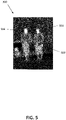
- Fig. 5 illustrates a radiometric image in accordance with an embodiment of the disclosure.
- Image 500 in Fig. 5 may be a radiometric image depicting thermal readings of a scene.
- Image 500 shows a radiometric image of two people walking.
- higher temperatures detected within the scene may correspond to pixels with brighter (e.g., whiter) pixel values while cooler temperatures may correspond to pixels with darker pixel values.
- image 500 there is an image center 502.
- the HDR to LDR compression may be lower for values of pixels within the image center 502.
- image 500 also includes two image hotspots, hotspot 504 and hotspot 506. Certain embodiments may detect hotspots with images, such as hotspots 504 and 506 within the image 500 and allow for lower HDR to LDR compression for values of pixels within the detected hotspots.
- pixels with pixel values that correspond relatively closely to human irradiance levels may also include lower HDR to LDR compression in some embodiments.
- a certain such embodiment may allow for lower HDR to LDR compression when a pixel with a pixel value that is roughly within 5 degrees Celsius of typical human irradiance levels is detected.
- such pixels may also include the pixels within the hotspots 504 and 506, as the hotspots 504 and 506 include pixels depicting the temperature of bare skin of two humans.
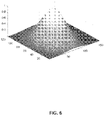
- Fig. 6 illustrates a high dynamic range to low dynamic range transfer function in accordance with an embodiment of the disclosure.
- the z-axis depicts a HDR to LDR gain.
- a gain value of 1 may correlate to a one-to-one transfer between HDR and LDR values.
- the other two axes represent pixel position.
- a weighting function is depicted. This weighting function may be used when calculating the metrics for each value or range of values of the vector/histogram. Using this weighting function will increase the value for the vector indices associated with values common in the center region of the image. If the transfer function slope/gain is proportional to this calculated weighted sum, objects near the center of the image may have less dynamic range compression and the reconstructed image may more closely reconstruct the HDR value to that of the original HDR value for this region.
- Figs. 7A-C illustrate additional high dynamic range to low dynamic range transfer functions in accordance with an embodiment of the disclosure.
- Fig. 7A illustrates a linear transfer function.
- Fig. 7B illustrates a transfer function with varying HDR to LDR gain/compression. It is appreciated that HDR to LDR gain may be inverse in relationship to HDR to LDR compression. That is, a lower HDR to LDR compression may denote a higher HDR to LDR gain.
- Fig. 7C illustrates a transfer function based on histogram equalization.
- the HDR image of Figs. 7A-C may be a 12 bit image with 4,096 possible image values.
- the LDR image of Figs 7A-C may be an 8 bit image with 256 image values.
- Figs. 7A-C illustrates a transfer function that may map image values of all possible image values within the HDR and LDR images
- other embodiments may map only a portion of the possible image values of the HDR and/or LDR images.
- the gain depicted in Figs. 7A-C may be shown to be continuous, the gain may actually be piecewise constant. Due to the resolution of Figs. 7A-C , such piecewise constant gain may be presented by a continuous slope, rather than as individual steps.
- the x-axis represents HDR image values of an HDR image while the x-axis represents LDR image values of a corresponding LDR version of the HDR image.
- the HDR to LDR gain is linear across the entire pixel range. That is, the lowest LDR image value may map to the 16 lowest HDR image values, the next lowest LDR image value may map to the next 16 lowest HDR image values, and so on with each LDR image value mapping to 16 HDR image values.
- the HDR to LDR gain may vary.
- Region 1 of Fig. 7B may be a region with a low HDR to LDR gain, while region 2 may be a region with the highest HDR to LDR gain of the three regions in Fig. 7B , and region 3 may be a region with a lower HDR to LDR gain than that of region 2.
- region 2 of Fig. 7B may correspond to image values within a region of interest, such as a hotspot, to image values that may be more important, such as image values that are around that of human irradiance values, or to image values that would otherwise be advantageous to transfer with higher fidelity/accuracy.
- the HDR to LDR gain of regions 1 and 3 may be lower than region 2, in order to accommodate the higher resolution of region 2.
- Fig. 7C shows a representation of the counts of the image values within a HDR image and the corresponding LDR image.
- the x-axis may correspond to the range of image values available within the respective images and the y-axis may correspond to the counts of the image values (e.g., the frequency of each image value).
- the HDR to LDR transfer function may be created using a histogram. That is, the slope of the transfer function for each HDR image value may be proportional to the amplitude of the histogram for that same HDR value. In Fig. 7C , this may result in the highest frequency/occurrence of image values near the middle of the available image values, while having smaller counts of image values near the extreme ends of the HDR dynamic range. In such a distribution, the relative counts of various image values may be retained during the HDR to LDR transfer.
- Figs. 8A-D illustrate various images captured and/or processed by an imaging system in accordance with an embodiment of the disclosure.
- Fig. 8A may show an original image captured by an imaging system.
- the image captured in Fig. 8A may be a radiometric HDR image that depicts a thermal reading of a scene.
- Fig. 8B may show a LDR version of the image of Fig. 8A a reduced dynamic range image that has been processed with a HDR to LDR transfer function. Also, additional filtering may also have been applied to the image of Fig. 8A before or after the image has been processed by the HDR to LDR transfer function.
- the image of Fig. 8B may be a LDR image received by a receiving device.
- Fig. 8C may show a version of the image of Fig. 8B that has been processed with an inverse transfer function to recreate an HDR radiometric image.
- the forward (HDR to LDR) transfer function may create an LDR image that, in some sense, may be optimal for viewing by a human observer.
- This LDR image may not preserve the relative signal differences within the HDR image, but may instead maximize the signal differences within the LDR image (as well as, possibly, the reconstructed HDR image) to more clearly show differences within the image.
- Fig. 8D may be a visualization of reconstruction error.
- the error may represent an absolute temperature measurement comparison between the images of Figs. 8A and 8C.
- Fig. 8D may show the differences in temperatures between corresponding pixels or regions of pixels of Figs. 8A and 8C .
- the maximum difference in temperature between the corresponding pixels of Figs. 8A and 8C is 15.64 mK (0.01564 degrees Kelvin / Celsius).
- the process described herein may allow accurate transfer of HDR radiometric images over a low bitrate interface.
- various embodiments provided by the present disclosure can be implemented using hardware, software, or combinations of hardware and software. Also where applicable, the various hardware components and/or software components set forth herein can be combined into composite components comprising software, hardware, and/or both without departing from the present disclosure. Where applicable, the various hardware components and/or software components set forth herein can be separated into sub-components comprising software, hardware, or both without departing from the present disclosure. In addition, where applicable, it is contemplated that software components can be implemented as hardware components, and vice-versa.
- Non-transitory instructions, program code, and/or data can be stored on one or more non-transitory machine readable mediums. It is also contemplated that software identified herein can be implemented using one or more general purpose or specific purpose computers and/or computer systems, networked and/or otherwise. Where applicable, the ordering of various steps described herein can be changed, combined into composite steps, and/or separated into sub-steps to provide features described herein.
Landscapes
- Engineering & Computer Science (AREA)
- Multimedia (AREA)
- Signal Processing (AREA)
- Physics & Mathematics (AREA)
- General Physics & Mathematics (AREA)
- Theoretical Computer Science (AREA)
- Studio Devices (AREA)
Claims (10)
- Procédé comprenant :la réception (300) d'une image thermique radiométrique de plage dynamique élevée (HDR) comprenant une pluralité de pixels, dans lequel chaque pixel est associé à une valeur d'image thermique HDR ;la détermination (320) d'une fonction de transfert, dans lequel la fonction de transfert associe au moins une partie des valeurs d'image thermique HDR à des valeurs d'image thermique de plage dynamique basse (LDR) ;la conversion (330), avec la fonction de transfert, de l'image thermique radiométrique HDR en une image thermique radiométrique de plage dynamique basse (LDR), dans lequel l'image thermique radiométrique LDR est une image présentant une plage dynamique inférieure à l'image thermique radiométrique HDR ;la détermination (360) d'une fonction de transfert inverse associée à la fonction de transfert ; etla transmission (350, 370) de la fonction de transfert inverse et de l'image thermique radiométrique LDR à un dispositif récepteur,dans lequel la détermination de la fonction de transfert comprend :la détermination d'un compte de valeurs uniques d'image thermique HDR dans l'image thermique radiométrique HDR ; etl'association de chacune des valeurs uniques d'image thermique HDR à une valeur disponible d'image thermique LDR, dans lequel l'association de chacune des valeurs uniques d'image thermique HDR comprend l'association de chacune des valeurs uniques d'image thermique HDR à des valeurs disponibles d'image thermique LDR en fonction d'une compression de HDR en LDR,dans lequel des valeurs d'image thermique HDR dans une région centrale de l'image thermique radiométrique HDR ont une compression de HDR en LDR inférieure, ou comprenant en outre la détermination d'au moins un point chaud dans l'image thermique radiométrique HDR, dans lequel des valeurs d'image thermique HDR dans le au moins un point chaud ont une compression de HDR en LDR inférieure, ou dans lequel des valeurs d'image thermique HDR radiométriquement associées à des niveaux d'irradiance humaine ont une compression de HDR en LDR inférieure.
- Procédé selon la revendication 1, comprenant en outre :le filtrage (310) d'au moins une partie de l'image thermique radiométrique HDR ;la compression (340) de l'image thermique radiométrique LDR, dans lequel la transmission de l'image thermique radiométrique LDR comprend la transmission de l'image thermique radiométrique LDR compressée ;la réception (410, 420) de la fonction de transfert inverse et de l'image thermique radiométrique LDR avec le dispositif récepteur ;la décompression (430), avec le dispositif récepteur après réception de l'image thermique radiométrique LDR, de l'image thermique radiométrique LDR reçue ; etla conversion (440), avec le dispositif récepteur et la fonction de transfert inverse, de l'image thermique radiométrique LDR en une image thermique reconstruite.
- Procédé selon la revendication 1, dans lequel la fonction de transfert inverse associe chaque valeur unique d'image thermique LDR à une ou plusieurs valeurs d'image thermique HDR de telle sorte que chaque valeur d'image thermique HDR est associée à une valeur d'image thermique LDR.
- Système comprenant :une caméra (102) configurée pour capturer des images thermiques radiométriques de plage dynamique élevée (HDR) et délivrer en sortie les images thermiques radiométriques HDR capturées ; etun dispositif logique (170) associé à la caméra, le dispositif logique étant configuré pour :recevoir (300) l'image thermique radiométrique HDR, dans lequel l'image thermique radiométrique HDR comprend une pluralité de pixels, dans lequel chaque pixel est associé à une valeur d'image thermique HDR ;déterminer (320) une fonction de transfert, dans lequel la fonction de transfert associe au moins une partie des valeurs d'image thermique HDR à des valeurs d'image thermique de plage dynamique basse (LDR) ;convertir (330), avec la fonction de transfert, l'image thermique radiométrique HDR en une image thermique radiométrique de plage dynamique basse (LDR), dans lequel l'image thermique radiométrique LDR est une image présentant une plage dynamique inférieure à l'image thermique radiométrique HDR ;déterminer (360) une fonction de transfert inverse associée à la fonction de transfert ; ettransmettre (350, 370) la fonction de transfert inverse et l'image thermique radiométrique LDR à un dispositif récepteur,dans lequel la détermination de la fonction de transfert comprend :la détermination d'un compte de valeurs uniques d'image thermique HDR dans l'image thermique radiométrique HDR ; etl'association de chacune des valeurs uniques d'image thermique HDR à une valeur disponible d'image thermique LDR,dans lequel l'association de chacune des valeurs uniques d'image thermique HDR comprend l'association de chacune des valeurs uniques d'image thermique HDR à des valeurs disponibles d'image thermique LDR en fonction d'une compression de HDR en LDR et dans lequel la compression de HDR en LDR est inférieure :dans une région centrale de l'image thermique radiométrique HDR ;dans un point chaud de l'image thermique radiométrique HDR ; et /oupour des valeurs d'image thermique HDR radiométriquement associées à des niveaux d'irradiance humaine.
- Système selon la revendication 4, dans lequel la caméra est configurée pour délivrer en sortie les images thermiques radiométriques HDR au dispositif logique par l'intermédiaire d'un réseau.
- Système selon la revendication 4, comprenant en outre une pluralité de caméras configurées pour capturer des images thermiques radiométriques HDR, dans lequel le dispositif logique est en outre configuré pour :recevoir des images thermiques radiométriques HDR provenant de chacune de la pluralité de caméras, chaque image thermique radiométrique HDR comprenant une pluralité de pixels, dans lequel chaque pixel est associé à une valeur d'image thermique HDR;déterminer au moins une fonction de transfert associée aux une ou plusieurs images thermiques radiométriques HDR, dans lequel la fonction de transfert associe au moins une partie des valeurs d'image thermique HDR à des valeurs d'image thermique LDR;convertir, avec la au moins une fonction de transfert, les images thermiques radiométriques HDR en images thermiques radiométriques à plage dynamique basse (LDR) ;déterminer une fonction de transfert inverse associée à chaque fonction de transfert ; ettransmettre la au moins une fonction de transfert inverse et les images thermiques radiométriques LDR à un dispositif récepteur.
- Système selon la revendication 4, dans lequel la fonction de transfert inverse associe chaque valeur unique d'image thermique LDR à une ou plusieurs valeurs d'image thermique HDR de telle sorte que chaque valeur d'image thermique HDR est associée à une valeur d'image thermique LDR.
- Système selon la revendication 4, comprenant en outre un dispositif récepteur (104) comprenant un dispositif de commande récepteur (110) et associé au dispositif logique (170), le dispositif de commande récepteur (110) étant configuré pour :recevoir (410) la fonction de transfert inverse ;recevoir (420) l'image thermique radiométrique LDR ; etconvertir (440), avec la fonction de transfert inverse, l'image thermique radiométrique LDR en une image thermique reconstruite.
- Système selon la revendication 8, dans lequel l'image thermique radiométrique LDR reçue est une image thermique radiométrique LDR compressée et le dispositif de commande récepteur (110) est en outre configuré pour décompresser (430) l'image thermique radiométrique LDR compressée.
- Système selon la revendication 8, comprenant en outre une interface utilisateur (140), dans lequel le dispositif de commande récepteur est en outre configuré pour délivrer en sortie (460) l'image thermique reconstruite à l'interface utilisateur (140).
Applications Claiming Priority (2)
| Application Number | Priority Date | Filing Date | Title |
|---|---|---|---|
| US201562220779P | 2015-09-18 | 2015-09-18 | |
| PCT/US2016/052017 WO2017049013A1 (fr) | 2015-09-18 | 2016-09-15 | Transfert d'images thermiques radiométriques de plage dynamique élevée sur une interface à faible débit binaire |
Publications (2)
| Publication Number | Publication Date |
|---|---|
| EP3350985A1 EP3350985A1 (fr) | 2018-07-25 |
| EP3350985B1 true EP3350985B1 (fr) | 2022-04-20 |
Family
ID=57043001
Family Applications (1)
| Application Number | Title | Priority Date | Filing Date |
|---|---|---|---|
| EP16774749.2A Active EP3350985B1 (fr) | 2015-09-18 | 2016-09-15 | Transfert d'images thermiques radiométriques de plage dynamique élevée sur une interface à faible débit binaire |
Country Status (4)
| Country | Link |
|---|---|
| US (1) | US10623667B2 (fr) |
| EP (1) | EP3350985B1 (fr) |
| CN (1) | CN108353136B (fr) |
| WO (1) | WO2017049013A1 (fr) |
Families Citing this family (8)
| Publication number | Priority date | Publication date | Assignee | Title |
|---|---|---|---|---|
| US11108995B2 (en) * | 2018-09-11 | 2021-08-31 | Draeger Medical Systems, Inc. | System and method for gas detection |
| US11890494B2 (en) | 2018-11-09 | 2024-02-06 | Qwake Technologies, Inc. | Retrofittable mask mount system for cognitive load reducing platform |
| US10417497B1 (en) | 2018-11-09 | 2019-09-17 | Qwake Technologies | Cognitive load reducing platform for first responders |
| US10896492B2 (en) | 2018-11-09 | 2021-01-19 | Qwake Technologies, Llc | Cognitive load reducing platform having image edge enhancement |
| US11301996B2 (en) | 2018-12-11 | 2022-04-12 | Eko.Ai Pte. Ltd. | Training neural networks of an automatic clinical workflow that recognizes and analyzes 2D and doppler modality echocardiogram images |
| US11446009B2 (en) | 2018-12-11 | 2022-09-20 | Eko.Ai Pte. Ltd. | Clinical workflow to diagnose heart disease based on cardiac biomarker measurements and AI recognition of 2D and doppler modality echocardiogram images |
| US11931207B2 (en) | 2018-12-11 | 2024-03-19 | Eko.Ai Pte. Ltd. | Artificial intelligence (AI) recognition of echocardiogram images to enhance a mobile ultrasound device |
| WO2021041990A1 (fr) | 2019-08-28 | 2021-03-04 | Qwake Technologies, Llc | Module de perception assistée pouvant être porté pour navigation et communication dans des environnements dangereux |
Family Cites Families (29)
| Publication number | Priority date | Publication date | Assignee | Title |
|---|---|---|---|---|
| US6088176A (en) * | 1993-04-30 | 2000-07-11 | International Business Machines Corporation | Method and apparatus for separating magnetic and thermal components from an MR read signal |
| US6091853A (en) * | 1995-08-28 | 2000-07-18 | Lockhead Martin Corporation | Local area linear dynamic range compression |
| FR2753279B1 (fr) * | 1996-09-09 | 1998-11-13 | Smv Int | Procede de traitement des impulsions delivrees par une gamma camera et gamma camera mettant en oeuvre ce procede |
| US6028309A (en) | 1997-02-11 | 2000-02-22 | Indigo Systems Corporation | Methods and circuitry for correcting temperature-induced errors in microbolometer focal plane array |
| US6798587B2 (en) * | 2002-03-08 | 2004-09-28 | Mikron Infrared, Inc. | Thermal imaging combination and method |
| JP3909529B2 (ja) * | 2004-08-26 | 2007-04-25 | パイオニア株式会社 | ディジタルフィルタ |
| US9948872B2 (en) * | 2009-03-02 | 2018-04-17 | Flir Systems, Inc. | Monitor and control systems and methods for occupant safety and energy efficiency of structures |
| US9819880B2 (en) * | 2009-06-03 | 2017-11-14 | Flir Systems, Inc. | Systems and methods of suppressing sky regions in images |
| JP2011150401A (ja) * | 2010-01-19 | 2011-08-04 | Yamaha Corp | ダイナミックレンジ圧縮装置およびプログラム |
| US20110205238A1 (en) * | 2010-02-23 | 2011-08-25 | Agfa Healthcare Inc. | Client browser image rendering method and system |
| US8737736B2 (en) * | 2010-12-31 | 2014-05-27 | Microsoft Corporation | Tone mapping of very large aerial image mosaic |
| JP2012213134A (ja) * | 2011-03-24 | 2012-11-01 | Sony Corp | 画像処理装置および方法 |
| WO2012142285A2 (fr) * | 2011-04-12 | 2012-10-18 | Dolby Laboratories Licensing Corporation | Estimation de la qualité d'images qui présentent des dynamiques étendues ou de larges gammes de couleurs |
| JP5992997B2 (ja) * | 2011-04-28 | 2016-09-14 | コーニンクレッカ フィリップス エヌ ヴェKoninklijke Philips N.V. | 映像符号化信号を発生する方法及び装置 |
| EP2702766B1 (fr) * | 2011-04-28 | 2017-06-14 | Koninklijke Philips N.V. | Appareils et procédés pour le codage et le décodage d'images à gamme dynamique élevée |
| US20130075371A1 (en) * | 2011-09-22 | 2013-03-28 | GM Global Technology Operations LLC | Non-destructive evaluation of welded joints of bar wound stator utilizing infrared and thermal methods |
| US9635220B2 (en) * | 2012-07-16 | 2017-04-25 | Flir Systems, Inc. | Methods and systems for suppressing noise in images |
| CN104620281B (zh) * | 2012-09-12 | 2018-08-14 | 皇家飞利浦有限公司 | 使hdr观看为内容所有者同意的过程 |
| US9064313B2 (en) * | 2012-09-28 | 2015-06-23 | Intel Corporation | Adaptive tone map to a region of interest to yield a low dynamic range image |
| CN103020998A (zh) * | 2012-11-19 | 2013-04-03 | 中山大学 | 一种基于边缘保持全分模型的色调映射方法 |
| KR102040149B1 (ko) * | 2013-02-01 | 2019-11-04 | 삼성전자주식회사 | 적외선 검출기 |
| US9710894B2 (en) * | 2013-06-04 | 2017-07-18 | Nvidia Corporation | System and method for enhanced multi-sample anti-aliasing |
| US9878804B2 (en) * | 2013-10-21 | 2018-01-30 | Eric Olsen | Systems and methods for producing temperature accurate thermal images |
| CN105917646B (zh) * | 2014-01-24 | 2021-10-08 | 索尼公司 | 发送装置、发送方法、接收装置和接收方法 |
| US9854176B2 (en) * | 2014-01-24 | 2017-12-26 | Lucasfilm Entertainment Company Ltd. | Dynamic lighting capture and reconstruction |
| CN104881644A (zh) * | 2015-05-25 | 2015-09-02 | 华南理工大学 | 非均匀光照条件下的人脸图像采集方法 |
| CN211825673U (zh) * | 2015-12-07 | 2020-10-30 | 菲力尔系统公司 | 成像装置 |
| US10140832B2 (en) * | 2016-01-26 | 2018-11-27 | Flir Systems, Inc. | Systems and methods for behavioral based alarms |
| CN109923580B (zh) * | 2016-11-04 | 2023-12-15 | 特利丹菲力尔有限责任公司 | 用于热视频的动态范围压缩 |
-
2016
- 2016-09-15 WO PCT/US2016/052017 patent/WO2017049013A1/fr active Application Filing
- 2016-09-15 CN CN201680066910.7A patent/CN108353136B/zh active Active
- 2016-09-15 EP EP16774749.2A patent/EP3350985B1/fr active Active
-
2018
- 2018-03-15 US US15/922,512 patent/US10623667B2/en active Active
Also Published As
| Publication number | Publication date |
|---|---|
| CN108353136B (zh) | 2021-06-04 |
| US20180205894A1 (en) | 2018-07-19 |
| US10623667B2 (en) | 2020-04-14 |
| EP3350985A1 (fr) | 2018-07-25 |
| WO2017049013A1 (fr) | 2017-03-23 |
| CN108353136A (zh) | 2018-07-31 |
Similar Documents
| Publication | Publication Date | Title |
|---|---|---|
| US10623667B2 (en) | High dynamic range radiometric thermal video over low bitrate interface | |
| US11010878B2 (en) | Dynamic range compression for thermal video | |
| US10694120B2 (en) | Methods for producing a temperature map of a scene | |
| US11012648B2 (en) | Anomalous pixel detection | |
| US10909364B2 (en) | Uncooled gas imaging camera | |
| KR102157675B1 (ko) | 촬영 장치 및 그 촬영 방법 | |
| EP3673646B1 (fr) | Assemblage d'images avec correction de l'obturateur roulant électronique | |
| US10146049B2 (en) | Cold weather camera kit | |
| WO2011112633A1 (fr) | Imageur avec réseaux de capteurs multiples | |
| US20220321777A1 (en) | Data rate control for image transmission | |
| US9875556B2 (en) | Edge guided interpolation and sharpening | |
| US20210073956A1 (en) | Image processing | |
| CN115209118A (zh) | 图像颜色校正系统和方法 | |
| KR20220085006A (ko) | 적외선 이미징-관련 불확실성 측정 시스템 및 방법 | |
| US11915394B2 (en) | Selective processing of anomalous pixels systems and methods | |
| US20220404593A1 (en) | Adjustable teleconverter systems and methods | |
| WO2023129559A1 (fr) | Systèmes et procédés de réduction d'ombrage d'image thermique | |
| CN115278191A (zh) | 图像白平衡方法及装置、计算机可读介质和电子设备 |
Legal Events
| Date | Code | Title | Description |
|---|---|---|---|
| STAA | Information on the status of an ep patent application or granted ep patent |
Free format text: STATUS: THE INTERNATIONAL PUBLICATION HAS BEEN MADE |
|
| PUAI | Public reference made under article 153(3) epc to a published international application that has entered the european phase |
Free format text: ORIGINAL CODE: 0009012 |
|
| STAA | Information on the status of an ep patent application or granted ep patent |
Free format text: STATUS: REQUEST FOR EXAMINATION WAS MADE |
|
| 17P | Request for examination filed |
Effective date: 20180319 |
|
| AK | Designated contracting states |
Kind code of ref document: A1 Designated state(s): AL AT BE BG CH CY CZ DE DK EE ES FI FR GB GR HR HU IE IS IT LI LT LU LV MC MK MT NL NO PL PT RO RS SE SI SK SM TR |
|
| AX | Request for extension of the european patent |
Extension state: BA ME |
|
| DAV | Request for validation of the european patent (deleted) | ||
| DAX | Request for extension of the european patent (deleted) | ||
| STAA | Information on the status of an ep patent application or granted ep patent |
Free format text: STATUS: EXAMINATION IS IN PROGRESS |
|
| 17Q | First examination report despatched |
Effective date: 20200903 |
|
| STAA | Information on the status of an ep patent application or granted ep patent |
Free format text: STATUS: EXAMINATION IS IN PROGRESS |
|
| GRAP | Despatch of communication of intention to grant a patent |
Free format text: ORIGINAL CODE: EPIDOSNIGR1 |
|
| STAA | Information on the status of an ep patent application or granted ep patent |
Free format text: STATUS: GRANT OF PATENT IS INTENDED |
|
| RIC1 | Information provided on ipc code assigned before grant |
Ipc: H04N 19/30 20140101ALI20211027BHEP Ipc: H04N 19/186 20140101ALI20211027BHEP Ipc: H04N 19/184 20140101ALI20211027BHEP Ipc: H04N 19/98 20140101ALI20211027BHEP Ipc: H04N 5/33 20060101AFI20211027BHEP |
|
| INTG | Intention to grant announced |
Effective date: 20211111 |
|
| RAP1 | Party data changed (applicant data changed or rights of an application transferred) |
Owner name: TELEDYNE FLIR, LLC |
|
| GRAS | Grant fee paid |
Free format text: ORIGINAL CODE: EPIDOSNIGR3 |
|
| GRAA | (expected) grant |
Free format text: ORIGINAL CODE: 0009210 |
|
| STAA | Information on the status of an ep patent application or granted ep patent |
Free format text: STATUS: THE PATENT HAS BEEN GRANTED |
|
| AK | Designated contracting states |
Kind code of ref document: B1 Designated state(s): AL AT BE BG CH CY CZ DE DK EE ES FI FR GB GR HR HU IE IS IT LI LT LU LV MC MK MT NL NO PL PT RO RS SE SI SK SM TR |
|
| REG | Reference to a national code |
Ref country code: GB Ref legal event code: FG4D |
|
| REG | Reference to a national code |
Ref country code: CH Ref legal event code: EP |
|
| REG | Reference to a national code |
Ref country code: DE Ref legal event code: R096 Ref document number: 602016071312 Country of ref document: DE |
|
| REG | Reference to a national code |
Ref country code: IE Ref legal event code: FG4D |
|
| REG | Reference to a national code |
Ref country code: AT Ref legal event code: REF Ref document number: 1486080 Country of ref document: AT Kind code of ref document: T Effective date: 20220515 |
|
| REG | Reference to a national code |
Ref country code: LT Ref legal event code: MG9D |
|
| REG | Reference to a national code |
Ref country code: NL Ref legal event code: MP Effective date: 20220420 |
|
| REG | Reference to a national code |
Ref country code: AT Ref legal event code: MK05 Ref document number: 1486080 Country of ref document: AT Kind code of ref document: T Effective date: 20220420 |
|
| PG25 | Lapsed in a contracting state [announced via postgrant information from national office to epo] |
Ref country code: NL Free format text: LAPSE BECAUSE OF FAILURE TO SUBMIT A TRANSLATION OF THE DESCRIPTION OR TO PAY THE FEE WITHIN THE PRESCRIBED TIME-LIMIT Effective date: 20220420 |
|
| PG25 | Lapsed in a contracting state [announced via postgrant information from national office to epo] |
Ref country code: SE Free format text: LAPSE BECAUSE OF FAILURE TO SUBMIT A TRANSLATION OF THE DESCRIPTION OR TO PAY THE FEE WITHIN THE PRESCRIBED TIME-LIMIT Effective date: 20220420 Ref country code: PT Free format text: LAPSE BECAUSE OF FAILURE TO SUBMIT A TRANSLATION OF THE DESCRIPTION OR TO PAY THE FEE WITHIN THE PRESCRIBED TIME-LIMIT Effective date: 20220822 Ref country code: NO Free format text: LAPSE BECAUSE OF FAILURE TO SUBMIT A TRANSLATION OF THE DESCRIPTION OR TO PAY THE FEE WITHIN THE PRESCRIBED TIME-LIMIT Effective date: 20220720 Ref country code: LT Free format text: LAPSE BECAUSE OF FAILURE TO SUBMIT A TRANSLATION OF THE DESCRIPTION OR TO PAY THE FEE WITHIN THE PRESCRIBED TIME-LIMIT Effective date: 20220420 Ref country code: HR Free format text: LAPSE BECAUSE OF FAILURE TO SUBMIT A TRANSLATION OF THE DESCRIPTION OR TO PAY THE FEE WITHIN THE PRESCRIBED TIME-LIMIT Effective date: 20220420 Ref country code: GR Free format text: LAPSE BECAUSE OF FAILURE TO SUBMIT A TRANSLATION OF THE DESCRIPTION OR TO PAY THE FEE WITHIN THE PRESCRIBED TIME-LIMIT Effective date: 20220721 Ref country code: FI Free format text: LAPSE BECAUSE OF FAILURE TO SUBMIT A TRANSLATION OF THE DESCRIPTION OR TO PAY THE FEE WITHIN THE PRESCRIBED TIME-LIMIT Effective date: 20220420 Ref country code: ES Free format text: LAPSE BECAUSE OF FAILURE TO SUBMIT A TRANSLATION OF THE DESCRIPTION OR TO PAY THE FEE WITHIN THE PRESCRIBED TIME-LIMIT Effective date: 20220420 Ref country code: BG Free format text: LAPSE BECAUSE OF FAILURE TO SUBMIT A TRANSLATION OF THE DESCRIPTION OR TO PAY THE FEE WITHIN THE PRESCRIBED TIME-LIMIT Effective date: 20220720 Ref country code: AT Free format text: LAPSE BECAUSE OF FAILURE TO SUBMIT A TRANSLATION OF THE DESCRIPTION OR TO PAY THE FEE WITHIN THE PRESCRIBED TIME-LIMIT Effective date: 20220420 |
|
| PG25 | Lapsed in a contracting state [announced via postgrant information from national office to epo] |
Ref country code: RS Free format text: LAPSE BECAUSE OF FAILURE TO SUBMIT A TRANSLATION OF THE DESCRIPTION OR TO PAY THE FEE WITHIN THE PRESCRIBED TIME-LIMIT Effective date: 20220420 Ref country code: PL Free format text: LAPSE BECAUSE OF FAILURE TO SUBMIT A TRANSLATION OF THE DESCRIPTION OR TO PAY THE FEE WITHIN THE PRESCRIBED TIME-LIMIT Effective date: 20220420 Ref country code: LV Free format text: LAPSE BECAUSE OF FAILURE TO SUBMIT A TRANSLATION OF THE DESCRIPTION OR TO PAY THE FEE WITHIN THE PRESCRIBED TIME-LIMIT Effective date: 20220420 Ref country code: IS Free format text: LAPSE BECAUSE OF FAILURE TO SUBMIT A TRANSLATION OF THE DESCRIPTION OR TO PAY THE FEE WITHIN THE PRESCRIBED TIME-LIMIT Effective date: 20220820 |
|
| REG | Reference to a national code |
Ref country code: DE Ref legal event code: R097 Ref document number: 602016071312 Country of ref document: DE |
|
| PG25 | Lapsed in a contracting state [announced via postgrant information from national office to epo] |
Ref country code: SM Free format text: LAPSE BECAUSE OF FAILURE TO SUBMIT A TRANSLATION OF THE DESCRIPTION OR TO PAY THE FEE WITHIN THE PRESCRIBED TIME-LIMIT Effective date: 20220420 Ref country code: SK Free format text: LAPSE BECAUSE OF FAILURE TO SUBMIT A TRANSLATION OF THE DESCRIPTION OR TO PAY THE FEE WITHIN THE PRESCRIBED TIME-LIMIT Effective date: 20220420 Ref country code: RO Free format text: LAPSE BECAUSE OF FAILURE TO SUBMIT A TRANSLATION OF THE DESCRIPTION OR TO PAY THE FEE WITHIN THE PRESCRIBED TIME-LIMIT Effective date: 20220420 Ref country code: EE Free format text: LAPSE BECAUSE OF FAILURE TO SUBMIT A TRANSLATION OF THE DESCRIPTION OR TO PAY THE FEE WITHIN THE PRESCRIBED TIME-LIMIT Effective date: 20220420 Ref country code: DK Free format text: LAPSE BECAUSE OF FAILURE TO SUBMIT A TRANSLATION OF THE DESCRIPTION OR TO PAY THE FEE WITHIN THE PRESCRIBED TIME-LIMIT Effective date: 20220420 Ref country code: CZ Free format text: LAPSE BECAUSE OF FAILURE TO SUBMIT A TRANSLATION OF THE DESCRIPTION OR TO PAY THE FEE WITHIN THE PRESCRIBED TIME-LIMIT Effective date: 20220420 |
|
| PLBE | No opposition filed within time limit |
Free format text: ORIGINAL CODE: 0009261 |
|
| STAA | Information on the status of an ep patent application or granted ep patent |
Free format text: STATUS: NO OPPOSITION FILED WITHIN TIME LIMIT |
|
| 26N | No opposition filed |
Effective date: 20230123 |
|
| PG25 | Lapsed in a contracting state [announced via postgrant information from national office to epo] |
Ref country code: AL Free format text: LAPSE BECAUSE OF FAILURE TO SUBMIT A TRANSLATION OF THE DESCRIPTION OR TO PAY THE FEE WITHIN THE PRESCRIBED TIME-LIMIT Effective date: 20220420 |
|
| PG25 | Lapsed in a contracting state [announced via postgrant information from national office to epo] |
Ref country code: MC Free format text: LAPSE BECAUSE OF FAILURE TO SUBMIT A TRANSLATION OF THE DESCRIPTION OR TO PAY THE FEE WITHIN THE PRESCRIBED TIME-LIMIT Effective date: 20220420 |
|
| REG | Reference to a national code |
Ref country code: CH Ref legal event code: PL |
|
| REG | Reference to a national code |
Ref country code: BE Ref legal event code: MM Effective date: 20220930 |
|
| PG25 | Lapsed in a contracting state [announced via postgrant information from national office to epo] |
Ref country code: SI Free format text: LAPSE BECAUSE OF FAILURE TO SUBMIT A TRANSLATION OF THE DESCRIPTION OR TO PAY THE FEE WITHIN THE PRESCRIBED TIME-LIMIT Effective date: 20220420 |
|
| PG25 | Lapsed in a contracting state [announced via postgrant information from national office to epo] |
Ref country code: LU Free format text: LAPSE BECAUSE OF NON-PAYMENT OF DUE FEES Effective date: 20220915 |
|
| PG25 | Lapsed in a contracting state [announced via postgrant information from national office to epo] |
Ref country code: LI Free format text: LAPSE BECAUSE OF NON-PAYMENT OF DUE FEES Effective date: 20220930 Ref country code: IE Free format text: LAPSE BECAUSE OF NON-PAYMENT OF DUE FEES Effective date: 20220915 Ref country code: CH Free format text: LAPSE BECAUSE OF NON-PAYMENT OF DUE FEES Effective date: 20220930 |
|
| PG25 | Lapsed in a contracting state [announced via postgrant information from national office to epo] |
Ref country code: BE Free format text: LAPSE BECAUSE OF NON-PAYMENT OF DUE FEES Effective date: 20220930 |
|
| PGFP | Annual fee paid to national office [announced via postgrant information from national office to epo] |
Ref country code: GB Payment date: 20230920 Year of fee payment: 8 |
|
| PGFP | Annual fee paid to national office [announced via postgrant information from national office to epo] |
Ref country code: FR Payment date: 20230927 Year of fee payment: 8 Ref country code: DE Payment date: 20230911 Year of fee payment: 8 |
|
| PG25 | Lapsed in a contracting state [announced via postgrant information from national office to epo] |
Ref country code: IT Free format text: LAPSE BECAUSE OF FAILURE TO SUBMIT A TRANSLATION OF THE DESCRIPTION OR TO PAY THE FEE WITHIN THE PRESCRIBED TIME-LIMIT Effective date: 20220420 |
|
| PG25 | Lapsed in a contracting state [announced via postgrant information from national office to epo] |
Ref country code: HU Free format text: LAPSE BECAUSE OF FAILURE TO SUBMIT A TRANSLATION OF THE DESCRIPTION OR TO PAY THE FEE WITHIN THE PRESCRIBED TIME-LIMIT; INVALID AB INITIO Effective date: 20160915 |
|
| PG25 | Lapsed in a contracting state [announced via postgrant information from national office to epo] |
Ref country code: CY Free format text: LAPSE BECAUSE OF FAILURE TO SUBMIT A TRANSLATION OF THE DESCRIPTION OR TO PAY THE FEE WITHIN THE PRESCRIBED TIME-LIMIT Effective date: 20220420 |