EP3098019B1 - Laserschweissvorrichtung mit spritzerschutzeinrichtung - Google Patents
Laserschweissvorrichtung mit spritzerschutzeinrichtung Download PDFInfo
- Publication number
- EP3098019B1 EP3098019B1 EP16171057.9A EP16171057A EP3098019B1 EP 3098019 B1 EP3098019 B1 EP 3098019B1 EP 16171057 A EP16171057 A EP 16171057A EP 3098019 B1 EP3098019 B1 EP 3098019B1
- Authority
- EP
- European Patent Office
- Prior art keywords
- nozzle
- optical system
- workpiece
- air
- laser beam
- Prior art date
- Legal status (The legal status is an assumption and is not a legal conclusion. Google has not performed a legal analysis and makes no representation as to the accuracy of the status listed.)
- Active
Links
Images

Classifications
-
- B—PERFORMING OPERATIONS; TRANSPORTING
- B23—MACHINE TOOLS; METAL-WORKING NOT OTHERWISE PROVIDED FOR
- B23K—SOLDERING OR UNSOLDERING; WELDING; CLADDING OR PLATING BY SOLDERING OR WELDING; CUTTING BY APPLYING HEAT LOCALLY, e.g. FLAME CUTTING; WORKING BY LASER BEAM
- B23K26/00—Working by laser beam, e.g. welding, cutting or boring
- B23K26/14—Working by laser beam, e.g. welding, cutting or boring using a fluid stream, e.g. a jet of gas, in conjunction with the laser beam; Nozzles therefor
- B23K26/142—Working by laser beam, e.g. welding, cutting or boring using a fluid stream, e.g. a jet of gas, in conjunction with the laser beam; Nozzles therefor for the removal of by-products
-
- B—PERFORMING OPERATIONS; TRANSPORTING
- B23—MACHINE TOOLS; METAL-WORKING NOT OTHERWISE PROVIDED FOR
- B23K—SOLDERING OR UNSOLDERING; WELDING; CLADDING OR PLATING BY SOLDERING OR WELDING; CUTTING BY APPLYING HEAT LOCALLY, e.g. FLAME CUTTING; WORKING BY LASER BEAM
- B23K26/00—Working by laser beam, e.g. welding, cutting or boring
- B23K26/16—Removal of by-products, e.g. particles or vapours produced during treatment of a workpiece
Definitions
- the invention relates to a laser welding device with welding optics for shaping a laser beam directed at a workpiece, and with a spatter protection device which has a fan and a nozzle for generating an air flow in a space between the welding optics and the workpiece, such that the air flow counteracts the spread of welding spatter to the welding optics, wherein the nozzle surrounds the laser beam in a ring shape and forms an exit gap running radially inwards and obliquely in the direction of the workpiece, and a ring of ventilation openings is provided to connect a space formed within the ring-shaped nozzle between the welding optics and the exit gap with the ambient air.
- Laser welding devices often have a laser beam source with an output of 4 to 8 kW.
- a welding head is usually held on a robot arm so that it can move in one or more axes and has welding optics through which the laser beam is focused on the workpiece.
- the high energy density of the laser beam often leads to the formation of welding spatter, i.e. molten particles are thrown away and/or combustion residues or coatings on the workpiece lead to the formation of smoke or fumes. These substances can easily damage or contaminate the welding optics.
- the welding optics are therefore usually protected by protective glass.
- this protective glass must also be of high optical quality and is therefore relatively expensive, especially with scanning welding devices in which the laser beam is deflected by a mirror system and the protective glass must therefore have a relatively large diameter.
- a device of this type is made of EN 10 2012 217082 A1
- Another laser welding device with a spatter protection device in the form of a ring nozzle is known in DE 102 26 359 A1 described. From DE 102 26 359 A1 and JP-H03 110094 A1 Devices of the type mentioned above are known in which the air flow is directed transversely to the laser beam.
- WO 2005/118210 A1 Material that is removed from a workpiece with a laser beam is sucked away by a vortex-shaped air stream in the direction of the laser beam source.
- WO 87/07862 , DE 39 35 009 A1 and EP 0 732 169 A1 describe other laser devices with jet nozzles.
- the object of the invention is to provide a laser welding device with an improved spatter protection device.
- the outlet gap contains swirl vanes and is designed in such a way that the air hits the axis of the welding optics radially from all sides and is deflected into an air vortex directed axially towards the workpiece surface and then flows away radially.
- the air is concentrated radially from all sides onto the axis of the welding optics and thus onto the laser beam. Since the air streams are also inclined at an angle towards the workpiece, they are deflected in an essentially axial direction when they meet on the axis of the welding optics, so that a powerful air stream is created that moves in the axial direction of the welding optics towards the workpiece and thus counteracts the welding spatter and gases thrown back from the workpiece. In this way, the spread of welding spatter and gases to the welding optics can be effectively prevented even with a relatively low air flow and relatively low input pressures.
- An additional advantage is that the air stream reaches close to the workpiece surface and only then flows off radially, which means that practically the entire propagation path of the laser beam is kept free of smoke and hot gases that could easily lead to defocusing and/or absorption of the laser beam.
- the ventilation openings allow pressure to be equalized in the space surrounding the nozzle. This prevents a negative pressure from developing in this space due to the suction of the air flow generated by the nozzle, which could cause dirt-laden air to be sucked into the welding optics.
- the swirl vanes improve the concentration of the air flow on the axis of the laser beam, creating an air vortex running along this axis in which high flow velocities occur, effectively preventing the spread of spatter and gases to the welding optics.
- a particular advantage of the invention is that no compressed air is required to generate sufficient air flow, but a simple blower is sufficient. This means that the energy costs for generating compressed air can be reduced by up to 90%, and installation and maintenance costs are also saved considerably.
- the blower that supplies the ring nozzle is relatively small and lightweight and can therefore be attached directly to the welding head or to the robot arm that supports the welding head.
- the welding head therefore does not need to be connected to the air source via flexible lines, which increases the freedom of movement of the welding head and enables precise and trouble-free control of the movement sequences.
- the laser welding device shown has a welding head 10 which is mounted at the end of a robot arm 12 and contains a welding optics 14 shown only schematically, with which a laser beam 16, which comes from a laser beam source not shown here is generated, is focused on a workpiece 18.
- the welding optics 14 are protected against welding spatter and smoke and vapors that can arise when welding the workpiece 18 by a protective glass 20 that is held replaceably on the front side of the welding head 10 with the aid of an annular flange 22.
- a support ring 26 is fastened to the annular flange 22 with the aid of holders 24 distributed around the circumference, and a nozzle 28 is held on said support ring, which surrounds the laser beam 16 in a ring shape.
- the nozzle has an annular channel 30, from which an annular nozzle 32 extends on the side facing away from the workpiece 18, which engages in the annular flange 22.
- An annular outlet gap 34 extends from the inner circumference of the annular channel 30, which is directed radially inwards and at an angle of approximately 20° towards the workpiece 18 and tapers slightly outwards in cross-section.
- the annular space 30 is connected via a supply line 36 to a blower 38 which is mounted on the outside of the welding head 10.
- the blower 38 generates an air flow which is distributed in the annular space 30 and is discharged via the outlet gap 34 from all sides evenly in the direction of the axis of the welding optics 14 and thus onto the laser beam 16.
- swirl vanes 40 are arranged in the outlet gap 34, which swirl the exiting air flow so that an air vortex 42 is formed in the space between the nozzle 28 and the workpiece 18.
- this air vortex 42 the air flowing in converging from all sides is deflected in the axial direction of the laser optics 14, so that a powerful swirling air flow is created, which spreads along the laser beam 16 to the workpiece 18 and only flows off radially at the workpiece surface.
- This air flow effectively holds back welding spatter as well as smoke and gases which spread in the direction of the protective glass 20 and leads them outwards so that they do not reach the protective glass 20.
- a ring of ventilation openings 44 is formed in the cylindrical nozzle 32 of the nozzle 28. Between the ring flange 22 and the support ring 26 there is a gap in the spaces between the holders 24 so that ambient air can flow through this gap and via the ventilation openings 44 into the space inside the nozzle 28 and above the outlet gap 34. In this way, the formation of a negative pressure in this space is prevented and thus dirt-laden air is prevented from being sucked in from the underside of the nozzle 28 and forming a dirt deposit on the protective glass 20.
- annular channel 46 is provided at the upper end of the nozzle 32, immediately adjacent to the protective glass 20, into which air cleaned and dried by an air cleaning unit 48 is fed. This air is discharged into the space below the protective glass 20 via a porous inner peripheral wall of the annular channel 46 or via small outlet nozzles in order to further reduce the risk of contamination or fogging of the protective glass.
- the blower 38 has a nominal output of 1600 watts and an air output of up to 35 l/s. This enables an air speed of around 600 km/h to be achieved in the outlet gap 34.
- the air enters the air vortex 42 at this speed, so that effective aerodynamic shielding of the protective glass 20 is achieved.
- the air exiting the outlet gap 34 at high speed forms a conical air curtain in the space surrounding the laser beam 16, which prevents contaminants from entering the nozzle 32 and then merges into the air vortex 42 on the axis of the laser beam 16.
- a very high flow velocity is achieved in the vortex core of this air vortex, so that hot gases and contaminants are effectively kept away from the zone in which the laser beam 16 spreads.
- a compressor with a nominal power of 40 kW and an air output of 5000 l/min would be required.
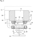
- Fig.3 shows an embodiment in which the nozzle 28 is designed separately from the nozzle 32 and is arranged at a greater distance from it.
- the nozzle 28 is held on the nozzle 32 by holders 24' distributed around the circumference, between which ventilation openings 44' are formed which have a very large cross-section and enable unhindered entry of ambient air into the space above the annular gap 34.
Landscapes
- Engineering & Computer Science (AREA)
- Physics & Mathematics (AREA)
- Optics & Photonics (AREA)
- Plasma & Fusion (AREA)
- Mechanical Engineering (AREA)
- Laser Beam Processing (AREA)
Description
- Die Erfindung betrifft eine Laserschweißvorrichtung mit einer Schweißoptik zur Strahlformung eines auf ein Werkstück gerichteten Laserstrahls, und mit einer Spritzerschutzeinrichtung, die ein Gebläse und eine Düse zur Erzeugung eines Luftstromes in einem Raum zwischen der Schweißoptik und dem Werkstück aufweist, derart, dass der Luftstrom einer Ausbreitung von Schweißspritzern zur Schweißoptik entgegen wirkt, wobei die Düse den Laserstrahl ringförmig umgibt und einen radial einwärts und schräg in Richtung auf das Werkstück verlaufenden Austrittsspalt bildet und ein Kranz von Lüftungsöffnungen dazu vorgesehen ist, einen innerhalb der ringförmigen Düse zwischen der Schweißoptik und dem Austrittsspalt gebildeten Raum mit der Umgebungsluft zu verbinden.
- Laserschweißvorrichtungen weisen häufig eine Laserstrahlquelle mit einer Leistung von 4 bis 8 kW auf. Ein Schweißkopf ist zumeist in einer oder mehreren Achsen beweglich an einem Roboterarm gehalten und weist eine Schweißoptik auf, durch die der Laserstrahl auf das Werkstück fokussiert wird. Beim Schweißen von beschichteten oder unbeschichteten Werkstücken aus Metall oder Kunststoff kommt es aufgrund der hohen Energiedichte des Laserstrahls oft zur Bildung von Schweißspritzern, d.h. schmelzflüssige Partikel werden weggeschleudert und/oder Verbrennungsrückstände oder Beschichtungen des Werkstücks führen zur Bildung von Schmauch oder Rauchgas. Diese Substanzen können leicht die Schweißoptik beschädigen oder verschmutzen. Die Schweißoptik wird deshalb zumeist durch ein Schutzglas geschützt. Auch dieses Schutzglas muss jedoch von hoher optischer Qualität sein und ist deshalb verhältnismäßig kostspielig, insbesondere bei scannenden Schweißvorrichtungen, bei denen der Laserstrahl über ein Spiegelsystem abgelenkt wird und demzufolge das Schutzglas einen relativ großen Durchmesser haben muss.
- Um das Schutzglas seinerseits gegen Schweißspritzer zu schützen, damit es nicht so häufig ausgewechselt werden muss, ist es bekannt, in dem Raum zwischen dem Schweißkopf und dem Werkstück seitlich neben dem Laserstrahl eine sogenannte Luftklinge anzuordnen, durch die Druckluft über eine Schlitzdüse in Richtung auf den Laserstrahl abgegeben wird. Auf diese Weise wird zwischen der Schweißoptik und dem Werkstück ein Luftvorhang gebildet, der das Vordringen von Schweißspritzern und Gasen bis zur Schweißoptik verhindern soll. Zur Erzeugung des Luftvorhangs wird Druckluft mit einem Eingangsdruck von 500 bis 1000 kPa benötigt, und der Luftdurchsatz liegt in der Größenordnung von einigen 1000 Normlitern pro Minute. Das Druckluftsystem erfordert deshalb einen hohen Energieeinsatz und führt außerdem zu hohen Installations- und Wartungskosten.
- Eine Vorrichtung dieser Art ist aus
DE 10 2012 217082 A1 bekannt. Eine andere Laserschweißvorrichtung mit einer Spritzerschutzeinrichtung in der Form einer Ringdüse wird inDE 102 26 359 A1 beschrieben. AusDE 102 26 359 A1 undJP H03 110094 A1 WO 2005/118210 A1 wird Material, das mit einem Laserstrahl von einem Werkstück abgetragen wird, durch einen wirbelförmigen Luftstrom in Richtung auf die Laserstrahlquelle abgesaugt.WO 87/07862 DE 39 35 009 A1 undEP 0 732 169 A1 beschreiben weitere Laservorrichtungen mit Strahldüsen. - Aufgabe der Erfindung ist es, eine Laserschweißvorrichtung mit einer verbesserten Spritzerschutzeinrichtung zu schaffen.
- Diese Aufgabe wird erfindungsgemäß dadurch gelöst, dass dass der Austrittsspalt Drallschaufeln enthält und so gestaltet ist, dass die Luft von allen Seiten her radial auf die Achse der Schweißoptik trifft und in einen axial auf die Werkstückoberfläche gerichteten Luftwirbel umgelenkt wird und dann radial abströmt..
- Durch den Austrittsspalt, der wahlweise auch durch eine Folge einzelner Austrittsöffnungen gebildet werden kann, wird die Luft von allen Seiten her radial auf die Achse der Schweißoptik und damit auf den Laserstrahl konzentriert. Da die Luftströme außerdem schräg in Richtung auf das Werkstück geneigt sind, werden sie beim Aufeinandertreffen auf der Achse der Schweißoptik in eine im wesentlichen axiale Richtung umgelenkt, so dass eine kräftige Luftströmung entsteht, die sich in Axialrichtung der Schweißoptik zu dem Werkstück bewegt und somit den vom Werkstück zurückgeschleuderten Schweißspritzern und Gasen entgegenkommt. Auf diese Weise lässt sich bereits mit verhältnismäßig geringem Luftdurchsatz und verhältnismäßig geringen Eingangsdrücken eine Ausbreitung der Schweißspritzer und Gase zur Schweißoptik wirksam verhindern. Ein zusätzlicher Vorteil ergibt sich daraus, dass die Luftströmung bis dicht an die Werkstückoberfläche heranreicht und erst dann radial abströmt, wodurch praktisch der gesamte Ausbreitungsweg des Laserstrahls von Rauch und heißen Gasen freigehalten wird, die leicht zu einer Defokussierung und/oder Absorption des Laserstrahls führen könnten. Die Lüftungsöffnungen ermöglichen einen Druckausgleich in dem von der Düse umgebenden Raum. Auf diese Weise wird verhindert, dass in diesem Raum aufgrund des Soges der von der Düse erzeugten Luftströmung ein Unterdruck entsteht, durch den schmutzbeladene Luft zur Schweißoptik hin angesaugt werden könnte.
- Durch die Drallschaufeln wird die Konzentration der Luftströmung auf die Achse des Laserstrahls verbessert, und es entsteht ein längs dieser Achse verlaufender Luftwirbel, in dem hohe Strömungsgeschwindigkeiten auftreten, die die Ausbreitung von Spritzern und Gasen zur Schweißoptik wirksam verhindern.
- Ein besonderer Vorteil der Erfindung besteht darin, dass zur Erzeugung einer ausreichenden Luftströmung keine Druckluft benötigt wird, sondern ein einfaches Gebläse genügt. Dadurch lassen sich die Energiekosten für die Drucklufterzeugung um bis zu 90% senken, und auch Installations- und Wartungskosten werden in erheblichem Umfang eingespart.
- Das Gebläse, aus dem die Ringdüse gespeist wird, hat verhältnismäßig geringe Abmessungen und ein verhältnismäßig geringes Gewicht und kann deshalb unmittelbar am Schweißkopf bzw. an dem Roboterarm angebracht werden, der den Schweißkopf trägt. Der Schweißkopf braucht deshalb nicht über flexible Leitungen mit der Luftquelle verbunden zu sein, wodurch die Bewegungsfreiheit des Schweißkopfes erhöht und eine präzise und störungsfreie Steuerung der Bewegungsabläufe ermöglicht wird. Außerdem entfallen Wartungskosten für den Ersatz der verschleißanfälligen flexiblen Druckluftleitungen.
- Im folgenden werden Ausführungsbeispiele anhand der Zeichnung näher erläutert.
- Es zeigen:
- Fig. 1
- einen axialen Schnitt durch einen Laserschweißkopf mit einer Spritzerschutzeinrichtung;
- Fig. 2
- einen Schnitt längs der Linie II - II in
Fig. 1 ; und - Fig. 3
- einen axialen Schnitt durch einen Laserschweißkopf mit einer Spritzerschutzeinrichtung gemäß einem anderen Ausführungsbeispiel.
- Die in
Fig. 1 gezeigte Laserschweißvorrichtung weist einen Schweißkopf 10 auf, der am ende eines Roboterarmes 12 montiert ist und eine nur schematisch gezeigte Schweißoptik 14 enthält, mit der ein Laserstrahl 16, der von einer hier nicht gezeigten Laserstrahlquelle erzeugt wird, auf ein Werkstück 18 fokussiert wird. Gegen Schweißspritzer und Rauch und Dämpfe, die beim Schweißen des Werkstücks 18 entstehen können, ist die Schweißoptik 14 durch ein Schutzglas 20 geschützt, das mit Hilfe eines Ringflansches 22 auswechselbar an der Stirnseite des Schweißkopfes 10 gehalten ist. An dem Ringflansch 22 ist mit Hilfe von auf den Umfang verteilten Haltern 24 ein Tragring 26 befestigt, an dem eine Düse 28 gehalten ist, die den Laserstrahl 16 ringförmig umgibt. Die Düse weist einen Ringkanal 30 auf, von dem auf der vom Werkstück 18 abgewandten Seite ein ringförmiger Stutzen 32 ausgeht, der in den Ringflansch 22 eingreift. Vom Inneren Umfang des Ringkanals 30 geht ein ringförmiger Austrittsspalt 34 aus, der radial nach innen und unter einem Winkel von etwa 20° schräg auf das Werkstück 18 gerichtet ist und sich im Querschnitt nach außen etwas verjüngt. - Der Ringraum 30 ist über eine Zufuhrleitung 36 mit einem Gebläse 38 verbunden, das außen an dem Schweißkopf 10 gehalten ist. Von dem Gebläse 38 wird ein Luftstrom erzeugt, der sich in dem Ringraum 30 verteilt und über den Austrittsspalt 34 von allen Seiten gleichmäßig in Richtung auf die Achse der Schweißoptik 14 und damit auf den Laserstrahl 16 abgegeben wird.
- Wie deutlicher in
Fig. 2 zu erkennen ist, sind in dem Austrittsspalt 34 Drallschaufeln 40 angeordnet, die den austretenden Luftstrom verdrallen, so dass in dem Raum zwischen der Düse 28 und dem Werkstück 18 ein Luftwirbel 42 gebildet wird. In diesem Luftwirbel 42 wird die von allen Seiten konvergierend einströmende Luft in Axialrichtung der Laseroptik 14 abgelenkt, so dass eine kräftige verdrallte Luftströmung entsteht, die sich längs des Laserstrahls 16 zu dem Werkstück 18 ausbreitet und erst an der Werkstückoberfläche radial abströmt. Durch diese Luftströmung werden Schweißspritzer sowie Rauch und Gase, die sich in Richtung auf das Schutzglas 20 ausbreiten, wirksam zurückgehalten und nach außen abgeführt, so dass sie das Schutzglas 20 nicht erreichen. - In dem zylindrischen Stutzen 32 der Düse 28 ist ein Kranz von Lüftungsöffnungen 44 gebildet. Zwischen dem Ringflansch 22 und dem Tragring 26 besteht in den Zwischenräumen zwischen den Haltern 24 ein Spalt, so dass Umgebungsluft durch diesen Spalt und über die Lüftungsöffnungen 44 in dem Raum im Inneren der Düse 28 und oberhalb des Austrittsspaltes 34 einströmen kann. Auf diese Weise wird die Entstehung eines Unterdrucks in diesem Raum verhindert und somit vermieden, dass schmutzbeladene Luft von der Unterseite der Düse 28 her angesaugt wird und einen Schmutzniederschlag auf dem Schutzglas 20 bildet.
- Im gezeigten Beispiel ist am oberen Ende des Stutzens 32, unmittelbar angrenzend an das Schutzglas 20 ein Ringkanal 46 vorgesehen, in den von einem Luftreinigungsaggregat 48 gereinigte und getrocknete Luft zugeführt wird. Diese Luft wird über eine poröse innere Umfangswand des Ringkanals 46 oder über kleine Auslassdüsen in den Raum unterhalb des Schutzglases 20 abgegeben, um die Gefahr einer Verschmutzung oder des Beschlagens des Schutzglases weiter zu verringern.
- In einem praktischen Beispiel hat das Gebläse 38 eine Nennleistung von 1600 Watt und eine Luftleistung von bis zu 35 l/s. Damit kann in dem Austrittsspalt 34 eine Luftgeschwindigkeit von etwa 600 km/h erreicht werden. Mit dieser Geschwindigkeit tritt die Luft in den Luftwirbel 42 ein, so dass eine wirksame aerodynamische Abschirmung des Schutzglases 20 erreicht wird. Die mit hoher Geschwindigkeit aus dem Austrittsspalt 34 austretende Luft bildet in dem Raum, der den Laserstrahl 16 umgibt, einen konischen Luftvorhang, der das Eindringen von Verunreinigungen in den Stutzen 32 verhindert und der dann auf der Achse des Laserstrahls 16 in den Luftwirbel 42 übergeht. Im Wirbelkern dieses Luftwirbels wird eine sehr hohe Strömungsgeschwindigkeit erreicht, so dass heiße Gase und Verunreinigungen wirksam aus der Zone ferngehalten werden, in der sich der Laserstrahl 16 ausbreitet. Um eine vergleichbare Abschirmungswirkung mit Hilfe Druckluft-Luftklingen zu erreichen, würde ein Kompressor mit einer Nennleistung von 40 kW und einer Luftleistung von 5000 l/min benötigt.
-
Fig. 3 zeigt ein Ausführungsbeispiel, bei dem die Düse 28 getrennt von dem Stutzen 32 ausgebildet und in größerem Abstand zu diesem angeordnet ist. Die Düse 28 ist an dem Stutzen 32 durch au dem Umfang verteilte Halter 24' gehalten, zwischen denen Lüftungsöffnungen 44' gebildet sind die einen sehr großen Querschnitt haben und einen ungehinderten Eintritt von Umgebungsluft in den Raum oberhalb des Ringspaltes 34 ermöglichen.
Claims (5)
- Laserschweißvorrichtung mit einer Schweißoptik (14) zur Strahlformung eines auf ein Werkstück (18) gerichteten Laserstrahls (16), und mit einer Spritzerschutzeinrichtung, die ein Gebläse (38) und eine Düse (28) zur Erzeugung eines Luftstromes (42) in einem Raum zwischen der Schweißoptik (14) und dem Werkstück (18) aufweist, derart dass eine kräftige Luftströmung entsteht, die sich in Axialrichtung der Schweißoptik bewegt und somit den vom Werkstück zurückgeschleuderten Schweißspritzern und Gasen entgegenkommt, wobei die Düse (28) den Laserstrahl (16) ringförmig umgibt und einen radial einwärts und schräg in Richtung auf das Werkstück (18) verlaufenden Austrittsspalt (34) bildet und Lüftungsöffnungen (44, 44') dazu vorgesehen sind, dass Umgebungsluft über die Luftöffnungen (44,44') in dem zwischen der Schweißoptik (14) und dem Austrittspalt (34) gebildeten Raum im Inneren der Düse (28) und oberhalb des Austrittspalt (34) einströmen kann, zeichnet, dass der Austrittsspalt (34) Drallschaufeln (40) enthält und so gestaltet ist, so dass in dem Raum zwischen der Düse (28) und dem Werkstück (18) ein Luftwirbel (42) gebildet wird, wobei die von allen Seiten konvergierend einströmende Luft in Axialrichtung der Laseroptik (14) abgelenkt wird, so dass eine kräftige verdrallte Luftströmung entsteht, die sich längs der Laserstrahls (16) zu dem Werkstück (18) ausbreitet und erst an der Werkstückoberfläche radial abströmt.
- Laserschweißvorrichtung nach Anspruch 1, bei der die Düse (28) einen Ringraum (30) aufweist, der eine Zufuhrleitung (36) des Gebläses (38) mit dem Austrittsspalt (34) verbindet.
- Laserschweißvorrichtung nach Anspruch 2, bei der die Schweißoptik (14) in einem Schweißkopf (10) gebildet ist und das Gebläse (38) an dem Schweißkopf (10) und/oder einem Roboterarm (12) angeordnet ist, der den Schweißkopf (10) trägt.
- Laserschweißvorrichtung nach einem der vorstehenden Ansprüche, bei der die Schweißoptik (14) in einem Schweißkopf (10) aufgenommen ist und die Düse (28) unmittelbar an dem Schweißkopf (10) gehalten ist.
- Laserschweißvorrichtung nach Anspruch 4, bei der die Düse (28) unmittelbar angrenzend an die Schweißoptik (14) eine Einrichtung zur Abgabe von gereinigter und/oder getrockneter Luft auf die Schweißoptik oder ein diese abdeckendes Schutzglas (20) aufweist.
Applications Claiming Priority (1)
| Application Number | Priority Date | Filing Date | Title |
|---|---|---|---|
| DE202015102740.0U DE202015102740U1 (de) | 2015-05-27 | 2015-05-27 | Laserschweißvorrichtung mit Spritzerschutzeinrichtung |
Publications (3)
| Publication Number | Publication Date |
|---|---|
| EP3098019A1 EP3098019A1 (de) | 2016-11-30 |
| EP3098019C0 EP3098019C0 (de) | 2024-09-25 |
| EP3098019B1 true EP3098019B1 (de) | 2024-09-25 |
Family
ID=56072278
Family Applications (1)
| Application Number | Title | Priority Date | Filing Date |
|---|---|---|---|
| EP16171057.9A Active EP3098019B1 (de) | 2015-05-27 | 2016-05-24 | Laserschweissvorrichtung mit spritzerschutzeinrichtung |
Country Status (5)
| Country | Link |
|---|---|
| EP (1) | EP3098019B1 (de) |
| DE (1) | DE202015102740U1 (de) |
| ES (1) | ES2999277T3 (de) |
| HU (1) | HUE069247T2 (de) |
| PL (1) | PL3098019T3 (de) |
Families Citing this family (8)
| Publication number | Priority date | Publication date | Assignee | Title |
|---|---|---|---|---|
| DE102019006647A1 (de) * | 2019-09-23 | 2021-03-25 | Rj Lasertechnik Gmbh | Schutzgasdüse zu Laserbearbeitung und Verfahren zum Laserbearbeiten |
| KR102383193B1 (ko) * | 2019-10-21 | 2022-04-06 | 삼성에스디아이 주식회사 | 레이저 용접 장치용 보호 모듈 |
| US12023757B2 (en) * | 2021-11-22 | 2024-07-02 | GM Global Technology Operations LLC | Air management system for laser welding with airflow optimizing deflector |
| CN114473261B (zh) * | 2022-02-28 | 2024-08-16 | 哈尔滨工大焊接科技有限公司 | 一种真空激光透射镜片保护系统及方法 |
| DE102022208240A1 (de) | 2022-08-08 | 2024-02-08 | Adient Us Llc | LUFTFÜHRUNGSVORRICHTUNG ZUR SPRITZERREDUKTION UND SPRITZERABLENKUNG BEIM LASERSTRAHLSCHWEIßEN UND SCHWEIßVORRICHTUNG |
| DE102023125996A1 (de) * | 2023-09-26 | 2025-03-27 | Fft Produktionssysteme Gmbh & Co. Kg | Druckluftdüseneinheit für einen Laserschweißkopf |
| EP4545235A1 (de) * | 2023-10-25 | 2025-04-30 | FRONIUS INTERNATIONAL GmbH | Einrichtung zur erzeugung einer luftströmung zum schutz des schutzglases einer laseroptik eines laser-hybrid-schweisskopfs sowie laser-hybrid-schweisskopf mit einer solchen einrichtung |
| CN119952243B (zh) * | 2025-03-20 | 2025-10-31 | 天津盛丰达机械制造有限公司 | 一种防金属飞溅的手持激光焊接机 |
Citations (3)
| Publication number | Priority date | Publication date | Assignee | Title |
|---|---|---|---|---|
| DE3935009A1 (de) * | 1989-10-20 | 1991-04-25 | Inst Nat Sciences Appliq | Vorrichtung fuer die laser-plasmabeschichtung |
| EP0732169A1 (de) * | 1995-03-16 | 1996-09-18 | HAAS-LASER GmbH | Vorrichtung zum Schutz der Bearbeitungsoptik eines Laser-Bearbeitungsgerätes vor Verschmutzung |
| DE102012217082A1 (de) * | 2012-09-21 | 2014-03-27 | Trumpf Laser Gmbh + Co. Kg | Laserbearbeitungskopf und Ringdüse für einen Laserbearbeitungskopf |
Family Cites Families (10)
| Publication number | Priority date | Publication date | Assignee | Title |
|---|---|---|---|---|
| JPS62224489A (ja) * | 1986-03-26 | 1987-10-02 | Mitsubishi Electric Corp | レ−ザ光学系保護装置 |
| JPH01503612A (ja) * | 1986-06-23 | 1989-12-07 | ユニバーシティ・オブ・テネシー・リサーチ・コーポレーション | レーザにより、持続されたプラズマトーチ及び該トーチの使用方法 |
| JPH03110094A (ja) * | 1989-09-22 | 1991-05-10 | Fanuc Ltd | レーザロボット用溶接ヘッド |
| TW270907B (de) * | 1992-10-23 | 1996-02-21 | Mitsubishi Electric Machine | |
| DE10160785C1 (de) * | 2001-12-11 | 2003-08-28 | Blz Gmbh | Begasungsdüseneinheit für den Bearbeitungskopf einer Laser-Schweißeinrichtung |
| DE10305258A1 (de) * | 2002-02-08 | 2003-08-21 | Creo Inc | Verfahren und Vorrichtung zum Schutz von optischen Elementen |
| DE10226359B4 (de) * | 2002-06-13 | 2010-08-19 | Precitec Kg | Laserbearbeitungskopf zur Bearbeitung, insbesondere zum Schneiden eines Werkstücks mittels Laserstrahl |
| EP1459835B1 (de) * | 2003-03-15 | 2013-04-24 | TRUMPF Werkzeugmaschinen GmbH + Co. KG | Laserbearbeitungsverfahren mit einem Laserbearbeitungskopf zum Laserschneiden und zum Laserschweissen |
| GB0412000D0 (en) * | 2004-05-28 | 2004-06-30 | Cambridge Display Tech Ltd | Apparatus and method for extracting debris during laser ablation |
| DE202005016574U1 (de) * | 2005-10-20 | 2007-02-08 | Kuka Schweissanlagen Gmbh | Blasvorrichtung für ein Laserwerkzeug |
-
2015
- 2015-05-27 DE DE202015102740.0U patent/DE202015102740U1/de not_active Expired - Lifetime
-
2016
- 2016-05-24 HU HUE16171057A patent/HUE069247T2/hu unknown
- 2016-05-24 EP EP16171057.9A patent/EP3098019B1/de active Active
- 2016-05-24 PL PL16171057.9T patent/PL3098019T3/pl unknown
- 2016-05-24 ES ES16171057T patent/ES2999277T3/es active Active
Patent Citations (3)
| Publication number | Priority date | Publication date | Assignee | Title |
|---|---|---|---|---|
| DE3935009A1 (de) * | 1989-10-20 | 1991-04-25 | Inst Nat Sciences Appliq | Vorrichtung fuer die laser-plasmabeschichtung |
| EP0732169A1 (de) * | 1995-03-16 | 1996-09-18 | HAAS-LASER GmbH | Vorrichtung zum Schutz der Bearbeitungsoptik eines Laser-Bearbeitungsgerätes vor Verschmutzung |
| DE102012217082A1 (de) * | 2012-09-21 | 2014-03-27 | Trumpf Laser Gmbh + Co. Kg | Laserbearbeitungskopf und Ringdüse für einen Laserbearbeitungskopf |
Also Published As
| Publication number | Publication date |
|---|---|
| PL3098019T3 (pl) | 2025-01-13 |
| ES2999277T3 (en) | 2025-02-25 |
| EP3098019A1 (de) | 2016-11-30 |
| DE202015102740U1 (de) | 2016-08-31 |
| EP3098019C0 (de) | 2024-09-25 |
| HUE069247T2 (hu) | 2025-02-28 |
Similar Documents
| Publication | Publication Date | Title |
|---|---|---|
| EP3098019A1 (de) | Laserschweissvorrichtung mit spritzerschutzeinrichtung | |
| DE10123097B4 (de) | Werkzeugkopf zur Lasermaterialbearbeitung | |
| EP1182002B1 (de) | Laserbearbeitungsmaschine mit wenigstens einem mit einem Spülmedium beaufschlagbaren optischen Element | |
| EP3110593B1 (de) | Laserbearbeitungskopf und verfahren zum laserbearbeiten mit einer werkstücknahen crossjetdüse | |
| DE102019103250B4 (de) | Laserbearbeitungskopf, bei dem eine Verschmutzung des Schutzfensters unterdrückt wird | |
| EP1629935B1 (de) | Laserbohrvorrichtung mit einer Strahldüse zur Erzeugung eines in Richtung der Bohrung strömenden Gasstrahles | |
| EP3755491B1 (de) | Laserbearbeitungskopf zum laser-draht-auftragschweissen | |
| DE10226359B4 (de) | Laserbearbeitungskopf zur Bearbeitung, insbesondere zum Schneiden eines Werkstücks mittels Laserstrahl | |
| EP3383576A1 (de) | Laserstrahl-bearbeitungsvorrichtung mit einer einkoppelvorrichtung zum einkoppeln eines fokussierten laserstrahls in einen flüssigkeitsstrahl | |
| EP0429942A2 (de) | Vorrichtung für den Stoffaustausch zwischen einem heissen Gasstrom und einer Flüssigkeit | |
| DE202016100923U1 (de) | Schweißvorrichtung mit Schutzgasführung | |
| DE102005025119B4 (de) | Vorrichtung zur Standzeiterhöhung von Laser-Bearbeitungsoptiken | |
| DE102022123817A1 (de) | Luftmanagementsystem für das laserschweissen mit luftstromoptimierendem deflektor | |
| DE102005028243C5 (de) | Düsenanordnung für einen Laserbearbeitungskopf | |
| DE102013214925A1 (de) | Einhausung für einen Strahlengang, Bearbeitungskammer und Verfahren zur Laserbearbeitung | |
| DE3931401C2 (de) | Fokussierkopf für Laserschweißanlagen | |
| EP3113904A1 (de) | Bearbeitungskopf und bearbeitungseinrichtung | |
| DE102014018624A1 (de) | Laservorrichtung zur Bearbeitung eines Werkstücks | |
| DE102016116659A1 (de) | Laserschweiß-Vorrichtung und Laserschweiß-Verfahren zum Laserschweißen metallischer Werkstücke | |
| WO2005099959A1 (de) | Verfahren sowie düse zur bearbeitung oder analyse eines werkstücks oder einer probe mit einem energetischen strahl | |
| EP2328712A1 (de) | Verfahren zum schneidgaslosen laserschmelzschneiden | |
| EP4568804A1 (de) | LUFTFÜHRUNGSVORRICHTUNG ZUR SPRITZERREDUKTION, SPRITZERABLENKUNG UND VERBESSERUNG EINER SCHWEIßNAHTQUALITÄT BEIM LASERSTRAHLSCHWEIßEN UND SCHWEIßVORRICHTUNG | |
| DE102006022282A1 (de) | Kaltgasspritzpistole | |
| DE202005008564U1 (de) | Vorrichtung zur Standzeiterhöhung von Laser-Bearbeitungsoptiken | |
| WO2019092270A1 (de) | Bearbeitungskopf und verfahren zur laserbearbeitung mit einem bearbeitungskopf |
Legal Events
| Date | Code | Title | Description |
|---|---|---|---|
| PUAI | Public reference made under article 153(3) epc to a published international application that has entered the european phase |
Free format text: ORIGINAL CODE: 0009012 |
|
| AK | Designated contracting states |
Kind code of ref document: A1 Designated state(s): AL AT BE BG CH CY CZ DE DK EE ES FI FR GB GR HR HU IE IS IT LI LT LU LV MC MK MT NL NO PL PT RO RS SE SI SK SM TR |
|
| AX | Request for extension of the european patent |
Extension state: BA ME |
|
| STAA | Information on the status of an ep patent application or granted ep patent |
Free format text: STATUS: REQUEST FOR EXAMINATION WAS MADE |
|
| 17P | Request for examination filed |
Effective date: 20170522 |
|
| RBV | Designated contracting states (corrected) |
Designated state(s): AL AT BE BG CH CY CZ DE DK EE ES FI FR GB GR HR HU IE IS IT LI LT LU LV MC MK MT NL NO PL PT RO RS SE SI SK SM TR |
|
| STAA | Information on the status of an ep patent application or granted ep patent |
Free format text: STATUS: EXAMINATION IS IN PROGRESS |
|
| 17Q | First examination report despatched |
Effective date: 20190424 |
|
| GRAP | Despatch of communication of intention to grant a patent |
Free format text: ORIGINAL CODE: EPIDOSNIGR1 |
|
| STAA | Information on the status of an ep patent application or granted ep patent |
Free format text: STATUS: GRANT OF PATENT IS INTENDED |
|
| INTG | Intention to grant announced |
Effective date: 20240503 |
|
| GRAS | Grant fee paid |
Free format text: ORIGINAL CODE: EPIDOSNIGR3 |
|
| GRAA | (expected) grant |
Free format text: ORIGINAL CODE: 0009210 |
|
| STAA | Information on the status of an ep patent application or granted ep patent |
Free format text: STATUS: THE PATENT HAS BEEN GRANTED |
|
| AK | Designated contracting states |
Kind code of ref document: B1 Designated state(s): AL AT BE BG CH CY CZ DE DK EE ES FI FR GB GR HR HU IE IS IT LI LT LU LV MC MK MT NL NO PL PT RO RS SE SI SK SM TR |
|
| REG | Reference to a national code |
Ref country code: GB Ref legal event code: FG4D Free format text: NOT ENGLISH |
|
| REG | Reference to a national code |
Ref country code: CH Ref legal event code: EP |
|
| REG | Reference to a national code |
Ref country code: DE Ref legal event code: R096 Ref document number: 502016016728 Country of ref document: DE |
|
| REG | Reference to a national code |
Ref country code: IE Ref legal event code: FG4D Free format text: LANGUAGE OF EP DOCUMENT: GERMAN |
|
| U01 | Request for unitary effect filed |
Effective date: 20241018 |
|
| U07 | Unitary effect registered |
Designated state(s): AT BE BG DE DK EE FI FR IT LT LU LV MT NL PT RO SE SI Effective date: 20241104 |
|
| REG | Reference to a national code |
Ref country code: SK Ref legal event code: T3 Ref document number: E 45318 Country of ref document: SK |
|
| PG25 | Lapsed in a contracting state [announced via postgrant information from national office to epo] |
Ref country code: NO Free format text: LAPSE BECAUSE OF FAILURE TO SUBMIT A TRANSLATION OF THE DESCRIPTION OR TO PAY THE FEE WITHIN THE PRESCRIBED TIME-LIMIT Effective date: 20241225 |
|
| PG25 | Lapsed in a contracting state [announced via postgrant information from national office to epo] |
Ref country code: GR Free format text: LAPSE BECAUSE OF FAILURE TO SUBMIT A TRANSLATION OF THE DESCRIPTION OR TO PAY THE FEE WITHIN THE PRESCRIBED TIME-LIMIT Effective date: 20241226 |
|
| PG25 | Lapsed in a contracting state [announced via postgrant information from national office to epo] |
Ref country code: RS Free format text: LAPSE BECAUSE OF FAILURE TO SUBMIT A TRANSLATION OF THE DESCRIPTION OR TO PAY THE FEE WITHIN THE PRESCRIBED TIME-LIMIT Effective date: 20241225 |
|
| PG25 | Lapsed in a contracting state [announced via postgrant information from national office to epo] |
Ref country code: RS Free format text: LAPSE BECAUSE OF FAILURE TO SUBMIT A TRANSLATION OF THE DESCRIPTION OR TO PAY THE FEE WITHIN THE PRESCRIBED TIME-LIMIT Effective date: 20241225 Ref country code: NO Free format text: LAPSE BECAUSE OF FAILURE TO SUBMIT A TRANSLATION OF THE DESCRIPTION OR TO PAY THE FEE WITHIN THE PRESCRIBED TIME-LIMIT Effective date: 20241225 Ref country code: GR Free format text: LAPSE BECAUSE OF FAILURE TO SUBMIT A TRANSLATION OF THE DESCRIPTION OR TO PAY THE FEE WITHIN THE PRESCRIBED TIME-LIMIT Effective date: 20241226 |
|
| REG | Reference to a national code |
Ref country code: ES Ref legal event code: FG2A Ref document number: 2999277 Country of ref document: ES Kind code of ref document: T3 Effective date: 20250225 |
|
| REG | Reference to a national code |
Ref country code: HU Ref legal event code: AG4A Ref document number: E069247 Country of ref document: HU |
|
| PG25 | Lapsed in a contracting state [announced via postgrant information from national office to epo] |
Ref country code: IS Free format text: LAPSE BECAUSE OF FAILURE TO SUBMIT A TRANSLATION OF THE DESCRIPTION OR TO PAY THE FEE WITHIN THE PRESCRIBED TIME-LIMIT Effective date: 20250125 |
|
| PG25 | Lapsed in a contracting state [announced via postgrant information from national office to epo] |
Ref country code: SM Free format text: LAPSE BECAUSE OF FAILURE TO SUBMIT A TRANSLATION OF THE DESCRIPTION OR TO PAY THE FEE WITHIN THE PRESCRIBED TIME-LIMIT Effective date: 20240925 |
|
| U20 | Renewal fee for the european patent with unitary effect paid |
Year of fee payment: 10 Effective date: 20250520 |
|
| PLBE | No opposition filed within time limit |
Free format text: ORIGINAL CODE: 0009261 |
|
| STAA | Information on the status of an ep patent application or granted ep patent |
Free format text: STATUS: NO OPPOSITION FILED WITHIN TIME LIMIT |
|
| 26N | No opposition filed |
Effective date: 20250626 |
|
| REG | Reference to a national code |
Ref country code: CH Ref legal event code: H13 Free format text: ST27 STATUS EVENT CODE: U-0-0-H10-H13 (AS PROVIDED BY THE NATIONAL OFFICE) Effective date: 20251223 |
|
| PG25 | Lapsed in a contracting state [announced via postgrant information from national office to epo] |
Ref country code: HR Free format text: LAPSE BECAUSE OF FAILURE TO SUBMIT A TRANSLATION OF THE DESCRIPTION OR TO PAY THE FEE WITHIN THE PRESCRIBED TIME-LIMIT Effective date: 20240925 |
|
| PG25 | Lapsed in a contracting state [announced via postgrant information from national office to epo] |
Ref country code: CH Free format text: LAPSE BECAUSE OF NON-PAYMENT OF DUE FEES Effective date: 20250531 |
|
| PG25 | Lapsed in a contracting state [announced via postgrant information from national office to epo] |
Ref country code: MC Free format text: LAPSE BECAUSE OF FAILURE TO SUBMIT A TRANSLATION OF THE DESCRIPTION OR TO PAY THE FEE WITHIN THE PRESCRIBED TIME-LIMIT Effective date: 20240925 |
|
| PG25 | Lapsed in a contracting state [announced via postgrant information from national office to epo] |
Ref country code: IE Free format text: LAPSE BECAUSE OF NON-PAYMENT OF DUE FEES Effective date: 20250524 |
|
| PGFP | Annual fee paid to national office [announced via postgrant information from national office to epo] |
Ref country code: HU Payment date: 20260514 Year of fee payment: 11 |
|
| U20 | Renewal fee for the european patent with unitary effect paid |
Year of fee payment: 11 Effective date: 20260520 |
|
| PGFP | Annual fee paid to national office [announced via postgrant information from national office to epo] |
Ref country code: ES Payment date: 20260618 Year of fee payment: 11 |
|
| PGFP | Annual fee paid to national office [announced via postgrant information from national office to epo] |
Ref country code: GB Payment date: 20260521 Year of fee payment: 11 Ref country code: PL Payment date: 20260508 Year of fee payment: 11 |
|
| PGFP | Annual fee paid to national office [announced via postgrant information from national office to epo] |
Ref country code: CZ Payment date: 20260511 Year of fee payment: 11 Ref country code: TR Payment date: 20260515 Year of fee payment: 11 |
|
| PGFP | Annual fee paid to national office [announced via postgrant information from national office to epo] |
Ref country code: SK Payment date: 20260520 Year of fee payment: 11 |
|
| PG25 | Lapsed in a contracting state [announced via postgrant information from national office to epo] |
Ref country code: CY Free format text: LAPSE BECAUSE OF FAILURE TO SUBMIT A TRANSLATION OF THE DESCRIPTION OR TO PAY THE FEE WITHIN THE PRESCRIBED TIME-LIMIT Effective date: 20240925 |