EP3097951B1 - Strahlentherapievorrichtung - Google Patents
Strahlentherapievorrichtung Download PDFInfo
- Publication number
- EP3097951B1 EP3097951B1 EP14879326.8A EP14879326A EP3097951B1 EP 3097951 B1 EP3097951 B1 EP 3097951B1 EP 14879326 A EP14879326 A EP 14879326A EP 3097951 B1 EP3097951 B1 EP 3097951B1
- Authority
- EP
- European Patent Office
- Prior art keywords
- gantry
- sliding members
- support
- rails
- radiation therapy
- Prior art date
- Legal status (The legal status is an assumption and is not a legal conclusion. Google has not performed a legal analysis and makes no representation as to the accuracy of the status listed.)
- Active
Links
Images


Classifications
-
- A—HUMAN NECESSITIES
- A61—MEDICAL OR VETERINARY SCIENCE; HYGIENE
- A61N—ELECTROTHERAPY; MAGNETOTHERAPY; RADIATION THERAPY; ULTRASOUND THERAPY
- A61N5/00—Radiation therapy
- A61N5/10—X-ray therapy; Gamma-ray therapy; Particle-irradiation therapy
- A61N5/1077—Beam delivery systems
- A61N5/1081—Rotating beam systems with a specific mechanical construction, e.g. gantries
-
- A—HUMAN NECESSITIES
- A61—MEDICAL OR VETERINARY SCIENCE; HYGIENE
- A61N—ELECTROTHERAPY; MAGNETOTHERAPY; RADIATION THERAPY; ULTRASOUND THERAPY
- A61N5/00—Radiation therapy
- A61N5/01—Devices for producing movement of radiation source during therapy
Definitions
- a method of treating tumors includes radiation therapy which irradiates an affected part with radiation.
- a radiation dose (a dose) for a patient it is preferable that a radiation dose (a dose) for a patient be reduced as small as possible and an affected part be efficiently irradiated with radiation. For this reason, stereotactic radiotherapy through which an affected part of a patient can be irradiated with radiation in multiple directions has been used.
- the annular support frame 1 for supporting the rails 2 should be configured to have a high strength to secure accuracy of the rails 2. As a result, an apparatus weight of the entire radiation therapy apparatus is increased.
- An aspect of the present invention is for the purpose of providing a radiation therapy apparatus capable of improving positional accuracy of a gantry, suppressing an increase in size of the apparatus, and reducing a weight of the apparatus.
- the rotation-driving mechanism in the radiation therapy apparatus of the first aspect may further comprise second sliding members which are provided at positions of the support which are laterally offset with respect to a vertical lower position of the central axis of the gantry, slidably guide the rails, and restrict displacement of the gantry in a horizontal direction.
- the radiation therapy apparatus may further include: a turning mechanism which supports the support in the radiation therapy apparatus of any one of the first to third aspects to be turnable about a vertical axis.
- the turning mechanism in the radiation therapy apparatus of any one of the first to fifth aspects includes a base installed on a floor; turning rails which are provided on one of the base and the support and continue in a circumferential direction centering on the vertical axis; turning guides which are provided on the other of the base and the support and are slidable along the turning rails, wherein an accommodating portion in which at least a portion of the gantry is accommodated in an inner circumferential side of the turning rails may be formed in the base.
- the radiation therapy apparatus 20 includes a gantry 30 and a radiation irradiating unit (an irradiation unit) 24.
- the gantry 30 has a circular cross-sectional cylindrical shape.
- the gantry 30 is configured to be pivotable in a vertical plane about a horizontal central axis C1 which extends in a horizontal direction using a vertical pivot mechanism (a rotation-driving mechanism) 40A (refer to Figs. 2 and 3 ) which will be described below.
- the gantry 30 is configured to be turnable in a horizontal plane about a vertical central axis (a vertical axis) C2 which extends in a vertical direction using a horizontal turn driving mechanism (a turning mechanism) 50A (refer to Figs. 2 and 3 ) which will be described below.
- the radiation irradiating unit 24 is supported by an inner circumferential surface 30a of the gantry 30.
- the radiation irradiating unit 24 is controlled by a control apparatus (not shown) and radiates therapeutic radiation Sr.
- the therapeutic radiation Sr radiated from the radiation irradiating unit 24 is adjusted to pass through an isocenter C0 set at an intersection of the horizontal central axis C1 and the vertical central axis C2.
- the radiation irradiating unit 24 is supported by the gantry 30 so that the therapeutic radiation Sr is always radiated to pass through the isocenter CO regardless of a rotational motion about the vertical central axis C2 of the gantry 30 and a rotational motion about the horizontal central axis C1 of the gantry 30.
- the radiation therapy apparatus 20 further includes a sensor array 22.
- the sensor array 22 receives the therapeutic radiation Sr radiated by the radiation irradiating unit 24 and passing through a subject near the isocenter CO and generates a transmitted image of the subject.
- a flat panel detector (FPD), an x-ray image intensifier (II), etc. can be used as the sensor array 22.
- the diagnostic x-ray sources 26A and 26B are disposed at an inner circumferential side of the gantry 30.
- the diagnostic x-ray sources 26A and 26B are disposed at both sides in a circumferential direction of the gantry 30 to surround a center (in other words, the vertical central axis C2) of the radiation therapy apparatus 20.
- the diagnostic x-ray sources 26A and 26B are controlled by the control apparatus (not shown) and radiate a diagnostic x-ray 101 toward the isocenter C0.
- the diagnostic x-ray 101 is a conical cone beam which spreads from one point of the diagnostic x-ray sources 26A and 26B in a conical shape.
- the diagnostic x-ray 101 is not limited to a conical shape and may be formed as, for example, a pyramidal shape, or the like by cutting out a necessary range using a collimator (not shown).
- the sensor arrays 27A and 27B are supported by the inner circumferential surface 30a of the gantry 30.
- the sensor arrays 27A and 27B are disposed to face the diagnostic x-ray sources 26A and 26B and to surround the isocenter C0.
- the sensor arrays 27A and 27B receive the diagnostic x-ray 101 radiated from the diagnostic x-ray sources 26A and 26B and passing through a subject near the isocenter CO and generate a transmitted image of the subject.
- an FPD, an x-ray II, or the like can be used as the sensor arrays 27A and 27B.
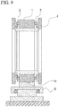
- Fig. 2 is a front view showing a driving mechanism of the gantry 30 in the radiation therapy apparatus 20 in a first embodiment.
- Fig. 3 is a side cross-sectional view showing the driving mechanism of the gantry 30.
- the radiation therapy apparatus 20 includes a vertical pivot mechanism 40A configured to support the gantry 30 to be pivotable about the horizontal central axis C1 which extends in the horizontal direction and a horizontal turn driving mechanism 50A configured to support the gantry 30 and the vertical pivot mechanism 40A to be turnable about the vertical central axis C2 which extends in the vertical direction.
- the gantry 30 includes a pair of annular ring frames 31 and 31 which are arranged in parallel to each other at an interval in a direction along the horizontal central axis C1.
- the ring frames 31 and 31 are integrally coupled using a plurality of coupling beam materials 32 which are provided at an interval in a circumferential direction.
- An inner circumferential side of the ring frames 31 is provided with a reinforcing material (not shown) having a truss structure, or the like for reinforcement.
- annular gantry rails (rails) 41 are integrally provided at sides at which the ring frames 31 face each other.
- the gantry 30 is covered by a cover 35, and the radiation therapy apparatus 20, the sensor array 22, the diagnostic x-ray sources 26A and 26B, the sensor arrays 27A and 27B are attached to the inner circumferential surface 30a of the gantry 30 as described above.
- the vertical pivot mechanism 40A includes the gantry rails 41 and sliding members (first sliding members) 45A and sliding members (second sliding members) 45B which are configured to slidably guide the gantry rails 41.
- the sliding members 45A and 45B are attached to a support 42A disposed between the pair of ring frames 31 and 31 which constitute the gantry 30.
- the sliding members 45A and 45B are provided at lateral surfaces 42s and 42s of the support 42A which face the pair of ring frames 31 and 31.
- the support 42A has a semi-annular arc shape which is provided in a range at a lower side than the horizontal central axis C1 of the gantry 30.
- the sliding members 45A are disposed in ranges of the lateral surfaces 42s of the support 42A which are at the lower side than the horizontal central axis C1 of the gantry 30.
- the sliding members 45A are disposed at a lowermost portion in a circumferential direction of the support 42A.
- the sliding members 45A are vertically under the horizontal central axis C1.
- the sliding members 45A support a lowermost portion in a circumferential direction of the gantry rails 41.
- a lowermost portion of the gantry rails 41 supported by the sliding members 45A extends substantially in a horizontal direction.
- the sliding members 45A restrict vertical displacement of the gantry rails 41 and support the gantry rails 41 to be slidable in the circumferential direction. In other words, the sliding members 45A receive a load in the vertical direction of the gantry 30 via the gantry rails 41.
- the sliding members 45B are attached to positions of the lateral surfaces 42s of the support 42A which are laterally offset with respect to a vertical lower position of the horizontal central axis C1 of the gantry 30.
- the sliding members 45B in the embodiment are arranged at slightly lower positions of both ends of the support 42A than the horizontal central axis C1.
- the lower base member 51 is installed on a floor F.
- the lower base member 51 includes a base plate 51a installed on the floor F and a columnar support shaft portion 51b standing on the base plate 51a.
- An upper end of the support shaft portion 51b is provided with an annular bearing 52.
- the upper base member 53 is installed on the lower base member 51.
- the upper base member 53 is configured to be rotatable about the vertical central axis C2 via the bearing 52 with respect to the lower base member 51.
- the upper base member 53 includes a base plate 53a which is supported to be rotatable by the bearing 52 and a rotational shaft portion (a rotational shaft) 53b standing on the base plate 53a.
- the rotational shaft portion 53b is integrally provided at a lowermost end of the support 42A.
- the affected part of the patient 200 is irradiated with a preset dose of therapeutic radiation Sr using the radiation irradiating unit 24.
- the vertical pivot mechanism 40B in the embodiment includes the gantry rails 41, sliding members (a first sliding member and a second sliding member) 45C and 45C which slidably guide the gantry rails 41.
- the vertical pivot mechanism 40C includes the gantry rails 41 and sliding members (a first sliding member and a second sliding member) 45D and 45D which slidably guide the gantry rails 41.
- the turning rails 57 are provided on the base 56 and are provided in an annular shape which continues in the circumferential direction centering on the vertical central axis C2.
- An opening portion 56a is formed at an inner circumferential side of the turning rails 57 in the base 56.
- the driving source 60 is integrally formed with the support 42C.
- the driving source 60 includes a circular arc-shaped gear 60a which is concentrically formed with one of the turning rails 57, and a motor 60c having a driving gear 60b meshed with the gear 60a.
- the driving gear 60b is rotatably driven by the motor 60c so that the support 42C and the gantry 30 can be turned about the vertical central axis C2 along with the circular arc-shaped gear 60a.
- the sliding members 45D and 45D receive the load in the vertical direction of the gantry 30 and restrict a displacement of the gantry 30 in a horizontal direction so that the gantry 30 can be stably rotated.
- two sliding members 45C and 45C and two sliding members 45D and 45D are configured to be provided.
- the second and third embodiments are not limited to such a constitution.
- An even number (four or more) of sliding members 45C and 45C and sliding members 45D and 45D may be disposed as long as they are disposed to surround the vertical central axis C2 of the gantry 30.
- dispositions of the sliding members 45C and 45C and the sliding members 45D and 45D are not limited to disposition which is symmetrically in line with respect to the vertical central axis C2 of the gantry 30 and can also be an asymmetrical disposition.
- the sliding members 45A which receive a load in the vertical direction of the gantry 30 may be provided at a position which is a lowermost portion of the support 42B between the two sliding members 45C and 45C and between the two sliding members 45D and 45D which has been described above as in the first embodiment.
- the sliding members 45A and 45C are disposed in the range which is vertically above the support shaft portion 51b and the rotational shaft portion 53b of the horizontal turn driving mechanism 50A.
- the present invention is not limited to this constitution, and for example, the sliding members 45A and 45C can also be disposed out of the range which is vertically above the support shaft portion 51b and the rotational shaft portion 53b of the horizontal turn driving mechanism 50A.
- the plurality of sliding members 45A and 45C may be provided in the range which is vertically above the rotational shaft portion 53b.
- the plurality of sliding members 45A and 45C may be symmetrically disposed to surround a position which is vertically above the rotational shaft portion 53b.
- the base 56 is provided with the turning rails 57, and the support 42C is provided with the turning guides 59 has been described.
- the support 42C may be provided with the turning rails 57 and the base 56 may be provided with the turning guides 59.
- a gantry is provided with annular rails, and first sliding members which slidably guide the rails and which receive at least a load in a vertical direction of the gantry are provided on a region corresponding to a lower half of the gantry in a support so that positional accuracy of the gantry can be increased, an increase in size of an apparatus can be suppressed, and a weight of the apparatus can be reduced.
Claims (6)
- Strahlentherapievorrichtung umfassend:ein ringförmiges Gestell (30);eine Bestrahlungseinheit (24), die auf dem Gestell vorgesehen und zur Abgabe von Strahlung eingerichtet ist;einen Träger, der das Gestell trägt;einen Rotationsantriebsmechanismus, der zwischen dem Gestell und dem Träger vorgesehen und eingerichtet ist, das Gestell um eine Mittelachse des Gestells rotieren zu lassen,wobei der Rotationsantriebsmechanismus folgendes umfasst:ringförmige Schienen (41), die auf dem Gestell vorgesehen sind; underste Gleitelemente (45A), die an Bereichen des Trägers vorgesehen sind, die einer unteren Hälfte auf der unteren Seite einer horizontalen Mittelachse (C1) des Gestells entsprechen,wobei die ersten Gleitelemente zum gleitenden Führen der Schienen und zur Aufnahme mindestens einer Last in vertikaler Richtung (C2) des Gestells eingerichtet sind.
- Strahlentherapievorrichtung nach Anspruch 1, wobei der Rotationsantriebsmechanismus außerdem zweite Gleitelemente (45B) umfasst, die an Orten des Trägers vorgesehen sind, die gegenüber einer vertikal unteren Position zur Mittelachse des Gestells seitlich versetzt sind, wobei die zweiten Gleitelemente zum gleitenden Führen der Schienen eingerichtet sind und einen Versatz des Gestells in horizontale Richtung einschränken.
- Strahlentherapievorrichtung nach Anspruch 2, wobei die ersten und die zweiten Gleitelemente axial zu einer durch die Mittelachse des Gestells hindurchtretenden vertikalen Achse symmetrisch angeordnet sind.
- Strahlentherapievorrichtung nach einem der Ansprüche 1 bis 3, weiterhin umfassend:
einen Drehmechanismus, der den Träger um eine vertikale Achse drehbar trägt. - Strahlentherapievorrichtung nach Anspruch 4, wobei der Drehmechanismus eine Drehwelle mit einer Mitte in Richtung einer vertikalen Achse aufweist, und
die ersten und die zweiten Gleitelemente vertikal über der Drehwelle angeordnet sind. - Strahlentherapievorrichtung nach Anspruch 4 oder 5, wobei der Drehmechanismus einen auf einem Boden installierten Sockel sowie folgendes enthält:Drehschienen, die vom Sockel und Träger auf einem davon vorgesehen sind und in Umfangsrichtung mit Zentrierung auf der vertikalen Achse verlaufen, undDrehführungen, die vom Sockel und Träger auf dem anderen davon vorgesehen sind und entlang der Drehschienen gleiten können,wobei in dem Sockel ein Aufnahmeabschnitt ausgebildet ist, in dem mindestens ein Teil des Gestells innenumfangsseitig der Drehschienen aufgenommen ist.
Applications Claiming Priority (1)
| Application Number | Priority Date | Filing Date | Title |
|---|---|---|---|
| PCT/JP2014/051090 WO2015111132A1 (ja) | 2014-01-21 | 2014-01-21 | 放射線治療装置 |
Publications (3)
| Publication Number | Publication Date |
|---|---|
| EP3097951A1 EP3097951A1 (de) | 2016-11-30 |
| EP3097951A4 EP3097951A4 (de) | 2017-02-22 |
| EP3097951B1 true EP3097951B1 (de) | 2018-07-25 |
Family
ID=53680968
Family Applications (1)
| Application Number | Title | Priority Date | Filing Date |
|---|---|---|---|
| EP14879326.8A Active EP3097951B1 (de) | 2014-01-21 | 2014-01-21 | Strahlentherapievorrichtung |
Country Status (4)
| Country | Link |
|---|---|
| US (1) | US10143860B2 (de) |
| EP (1) | EP3097951B1 (de) |
| JP (1) | JP6114409B2 (de) |
| WO (1) | WO2015111132A1 (de) |
Families Citing this family (3)
| Publication number | Priority date | Publication date | Assignee | Title |
|---|---|---|---|---|
| CN114306957A (zh) * | 2017-02-13 | 2022-04-12 | 西安大医集团股份有限公司 | 一种放射治疗设备 |
| CN109200485B (zh) * | 2018-09-20 | 2024-02-02 | 成都真实维度科技有限公司 | 一种用于多点共面激光引导照射的角度偏移装置 |
| US20230390587A1 (en) * | 2020-10-16 | 2023-12-07 | The Johns Hopkins University | Ultra-high dose rate x-ray cabinet irradiator |
Family Cites Families (11)
| Publication number | Priority date | Publication date | Assignee | Title |
|---|---|---|---|---|
| DE2608461A1 (de) * | 1976-03-01 | 1977-09-15 | Siemens Ag | Roentgenuntersuchungsgeraet |
| US5473657A (en) * | 1994-02-08 | 1995-12-05 | Analogic Corporation | X-ray tomographic scanning system |
| JPH09304303A (ja) | 1996-05-15 | 1997-11-28 | Hitachi Eng & Services Co Ltd | 可搬型x線ct装置 |
| DE19947809A1 (de) * | 1999-10-05 | 2001-04-12 | Philips Corp Intellectual Pty | C-Bogen-Röntgeneinrichtung |
| JP2002325854A (ja) * | 2001-05-01 | 2002-11-12 | Hitachi Medical Corp | 放射線治療装置 |
| EP1482837B1 (de) | 2002-03-13 | 2005-09-14 | Breakaway Imaging, Llc | Systeme und verfahren für die quasi-gleichzeitige multiplanare röntgendarstellung |
| JP2006021046A (ja) | 2005-07-05 | 2006-01-26 | Mitsubishi Heavy Ind Ltd | 放射線治療装置 |
| JP4228019B2 (ja) | 2007-02-16 | 2009-02-25 | 三菱重工業株式会社 | 医療装置 |
| JP4461152B2 (ja) * | 2007-02-16 | 2010-05-12 | 三菱重工業株式会社 | 放射線治療装置 |
| CN102551773B (zh) * | 2010-12-10 | 2015-11-25 | Ge医疗系统环球技术有限公司 | 用于ct扫描架的自调整轴承 |
| US10124193B2 (en) | 2012-02-29 | 2018-11-13 | Hitachi, Ltd. | X-ray therapy system and irradiation field determining method |
-
2014
- 2014-01-21 JP JP2015558621A patent/JP6114409B2/ja active Active
- 2014-01-21 WO PCT/JP2014/051090 patent/WO2015111132A1/ja active Application Filing
- 2014-01-21 EP EP14879326.8A patent/EP3097951B1/de active Active
- 2014-01-21 US US15/111,371 patent/US10143860B2/en active Active
Non-Patent Citations (1)
| Title |
|---|
| None * |
Also Published As
| Publication number | Publication date |
|---|---|
| US20160332001A1 (en) | 2016-11-17 |
| JP6114409B2 (ja) | 2017-04-12 |
| JPWO2015111132A1 (ja) | 2017-03-23 |
| WO2015111132A1 (ja) | 2015-07-30 |
| US10143860B2 (en) | 2018-12-04 |
| EP3097951A4 (de) | 2017-02-22 |
| EP3097951A1 (de) | 2016-11-30 |
Similar Documents
| Publication | Publication Date | Title |
|---|---|---|
| JP4936924B2 (ja) | 粒子線照射システム | |
| JP6654102B2 (ja) | 粒子線治療システム | |
| US8878142B2 (en) | Charged particle beam irradiation apparatus | |
| EP3097951B1 (de) | Strahlentherapievorrichtung | |
| US20120205555A1 (en) | Holding arm and arrangement for supporting diagnostic irradiation in radiation therapy applications | |
| CN104968394A (zh) | 粒子射线旋转照射装置及粒子射线治疗装置 | |
| US20160206899A1 (en) | Multileaf collimator, and radiation therapy apparatus and radiation therapy system using same | |
| CN110234396B (zh) | 一种放射治疗设备 | |
| JP4436343B2 (ja) | マルチリーフコリメータおよび放射線治療装置組立方法 | |
| JP5829162B2 (ja) | X線撮影装置 | |
| JP5680510B2 (ja) | 荷電粒子線照射装置 | |
| AU2012289817B2 (en) | An image-guided radiation therapy assembly | |
| JP4461152B2 (ja) | 放射線治療装置 | |
| KR101796512B1 (ko) | 유지 보수가 편리한 듀얼 헤드 타입의 방사선 치료장치 | |
| JP6012245B2 (ja) | 粒子線回転照射装置 | |
| US10201719B2 (en) | Gantry system for particle beam therapy | |
| WO2022170603A1 (zh) | 放射治疗设备及其控制方法 | |
| US10653895B2 (en) | Radiotherapy apparatus | |
| JP2002325854A (ja) | 放射線治療装置 | |
| JP2004049514A (ja) | 放射線治療装置 | |
| JP2015173706A (ja) | 荷電粒子線治療装置 |
Legal Events
| Date | Code | Title | Description |
|---|---|---|---|
| PUAI | Public reference made under article 153(3) epc to a published international application that has entered the european phase |
Free format text: ORIGINAL CODE: 0009012 |
|
| 17P | Request for examination filed |
Effective date: 20160714 |
|
| AK | Designated contracting states |
Kind code of ref document: A1 Designated state(s): AL AT BE BG CH CY CZ DE DK EE ES FI FR GB GR HR HU IE IS IT LI LT LU LV MC MK MT NL NO PL PT RO RS SE SI SK SM TR |
|
| AX | Request for extension of the european patent |
Extension state: BA ME |
|
| A4 | Supplementary search report drawn up and despatched |
Effective date: 20170120 |
|
| RIC1 | Information provided on ipc code assigned before grant |
Ipc: A61N 5/10 20060101AFI20170116BHEP Ipc: A61N 5/01 20060101ALI20170116BHEP |
|
| DAX | Request for extension of the european patent (deleted) | ||
| RAP1 | Party data changed (applicant data changed or rights of an application transferred) |
Owner name: HITACHI, LTD. |
|
| GRAP | Despatch of communication of intention to grant a patent |
Free format text: ORIGINAL CODE: EPIDOSNIGR1 |
|
| STAA | Information on the status of an ep patent application or granted ep patent |
Free format text: STATUS: GRANT OF PATENT IS INTENDED |
|
| INTG | Intention to grant announced |
Effective date: 20180212 |
|
| GRAS | Grant fee paid |
Free format text: ORIGINAL CODE: EPIDOSNIGR3 |
|
| GRAA | (expected) grant |
Free format text: ORIGINAL CODE: 0009210 |
|
| STAA | Information on the status of an ep patent application or granted ep patent |
Free format text: STATUS: THE PATENT HAS BEEN GRANTED |
|
| AK | Designated contracting states |
Kind code of ref document: B1 Designated state(s): AL AT BE BG CH CY CZ DE DK EE ES FI FR GB GR HR HU IE IS IT LI LT LU LV MC MK MT NL NO PL PT RO RS SE SI SK SM TR |
|
| REG | Reference to a national code |
Ref country code: GB Ref legal event code: FG4D |
|
| REG | Reference to a national code |
Ref country code: CH Ref legal event code: EP |
|
| REG | Reference to a national code |
Ref country code: AT Ref legal event code: REF Ref document number: 1021114 Country of ref document: AT Kind code of ref document: T Effective date: 20180815 |
|
| REG | Reference to a national code |
Ref country code: IE Ref legal event code: FG4D |
|
| REG | Reference to a national code |
Ref country code: DE Ref legal event code: R096 Ref document number: 602014029361 Country of ref document: DE |
|
| REG | Reference to a national code |
Ref country code: NL Ref legal event code: MP Effective date: 20180725 |
|
| REG | Reference to a national code |
Ref country code: LT Ref legal event code: MG4D |
|
| PG25 | Lapsed in a contracting state [announced via postgrant information from national office to epo] |
Ref country code: NL Free format text: LAPSE BECAUSE OF FAILURE TO SUBMIT A TRANSLATION OF THE DESCRIPTION OR TO PAY THE FEE WITHIN THE PRESCRIBED TIME-LIMIT Effective date: 20180725 |
|
| REG | Reference to a national code |
Ref country code: AT Ref legal event code: MK05 Ref document number: 1021114 Country of ref document: AT Kind code of ref document: T Effective date: 20180725 |
|
| PG25 | Lapsed in a contracting state [announced via postgrant information from national office to epo] |
Ref country code: FI Free format text: LAPSE BECAUSE OF FAILURE TO SUBMIT A TRANSLATION OF THE DESCRIPTION OR TO PAY THE FEE WITHIN THE PRESCRIBED TIME-LIMIT Effective date: 20180725 Ref country code: IS Free format text: LAPSE BECAUSE OF FAILURE TO SUBMIT A TRANSLATION OF THE DESCRIPTION OR TO PAY THE FEE WITHIN THE PRESCRIBED TIME-LIMIT Effective date: 20181125 Ref country code: BG Free format text: LAPSE BECAUSE OF FAILURE TO SUBMIT A TRANSLATION OF THE DESCRIPTION OR TO PAY THE FEE WITHIN THE PRESCRIBED TIME-LIMIT Effective date: 20181025 Ref country code: SE Free format text: LAPSE BECAUSE OF FAILURE TO SUBMIT A TRANSLATION OF THE DESCRIPTION OR TO PAY THE FEE WITHIN THE PRESCRIBED TIME-LIMIT Effective date: 20180725 Ref country code: AT Free format text: LAPSE BECAUSE OF FAILURE TO SUBMIT A TRANSLATION OF THE DESCRIPTION OR TO PAY THE FEE WITHIN THE PRESCRIBED TIME-LIMIT Effective date: 20180725 Ref country code: NO Free format text: LAPSE BECAUSE OF FAILURE TO SUBMIT A TRANSLATION OF THE DESCRIPTION OR TO PAY THE FEE WITHIN THE PRESCRIBED TIME-LIMIT Effective date: 20181025 Ref country code: LT Free format text: LAPSE BECAUSE OF FAILURE TO SUBMIT A TRANSLATION OF THE DESCRIPTION OR TO PAY THE FEE WITHIN THE PRESCRIBED TIME-LIMIT Effective date: 20180725 Ref country code: GR Free format text: LAPSE BECAUSE OF FAILURE TO SUBMIT A TRANSLATION OF THE DESCRIPTION OR TO PAY THE FEE WITHIN THE PRESCRIBED TIME-LIMIT Effective date: 20181026 Ref country code: RS Free format text: LAPSE BECAUSE OF FAILURE TO SUBMIT A TRANSLATION OF THE DESCRIPTION OR TO PAY THE FEE WITHIN THE PRESCRIBED TIME-LIMIT Effective date: 20180725 Ref country code: PL Free format text: LAPSE BECAUSE OF FAILURE TO SUBMIT A TRANSLATION OF THE DESCRIPTION OR TO PAY THE FEE WITHIN THE PRESCRIBED TIME-LIMIT Effective date: 20180725 |
|
| PG25 | Lapsed in a contracting state [announced via postgrant information from national office to epo] |
Ref country code: LV Free format text: LAPSE BECAUSE OF FAILURE TO SUBMIT A TRANSLATION OF THE DESCRIPTION OR TO PAY THE FEE WITHIN THE PRESCRIBED TIME-LIMIT Effective date: 20180725 Ref country code: AL Free format text: LAPSE BECAUSE OF FAILURE TO SUBMIT A TRANSLATION OF THE DESCRIPTION OR TO PAY THE FEE WITHIN THE PRESCRIBED TIME-LIMIT Effective date: 20180725 Ref country code: HR Free format text: LAPSE BECAUSE OF FAILURE TO SUBMIT A TRANSLATION OF THE DESCRIPTION OR TO PAY THE FEE WITHIN THE PRESCRIBED TIME-LIMIT Effective date: 20180725 |
|
| REG | Reference to a national code |
Ref country code: DE Ref legal event code: R097 Ref document number: 602014029361 Country of ref document: DE |
|
| PG25 | Lapsed in a contracting state [announced via postgrant information from national office to epo] |
Ref country code: ES Free format text: LAPSE BECAUSE OF FAILURE TO SUBMIT A TRANSLATION OF THE DESCRIPTION OR TO PAY THE FEE WITHIN THE PRESCRIBED TIME-LIMIT Effective date: 20180725 Ref country code: IT Free format text: LAPSE BECAUSE OF FAILURE TO SUBMIT A TRANSLATION OF THE DESCRIPTION OR TO PAY THE FEE WITHIN THE PRESCRIBED TIME-LIMIT Effective date: 20180725 Ref country code: EE Free format text: LAPSE BECAUSE OF FAILURE TO SUBMIT A TRANSLATION OF THE DESCRIPTION OR TO PAY THE FEE WITHIN THE PRESCRIBED TIME-LIMIT Effective date: 20180725 Ref country code: CZ Free format text: LAPSE BECAUSE OF FAILURE TO SUBMIT A TRANSLATION OF THE DESCRIPTION OR TO PAY THE FEE WITHIN THE PRESCRIBED TIME-LIMIT Effective date: 20180725 Ref country code: RO Free format text: LAPSE BECAUSE OF FAILURE TO SUBMIT A TRANSLATION OF THE DESCRIPTION OR TO PAY THE FEE WITHIN THE PRESCRIBED TIME-LIMIT Effective date: 20180725 |
|
| PG25 | Lapsed in a contracting state [announced via postgrant information from national office to epo] |
Ref country code: SM Free format text: LAPSE BECAUSE OF FAILURE TO SUBMIT A TRANSLATION OF THE DESCRIPTION OR TO PAY THE FEE WITHIN THE PRESCRIBED TIME-LIMIT Effective date: 20180725 Ref country code: DK Free format text: LAPSE BECAUSE OF FAILURE TO SUBMIT A TRANSLATION OF THE DESCRIPTION OR TO PAY THE FEE WITHIN THE PRESCRIBED TIME-LIMIT Effective date: 20180725 Ref country code: SK Free format text: LAPSE BECAUSE OF FAILURE TO SUBMIT A TRANSLATION OF THE DESCRIPTION OR TO PAY THE FEE WITHIN THE PRESCRIBED TIME-LIMIT Effective date: 20180725 |
|
| PLBE | No opposition filed within time limit |
Free format text: ORIGINAL CODE: 0009261 |
|
| STAA | Information on the status of an ep patent application or granted ep patent |
Free format text: STATUS: NO OPPOSITION FILED WITHIN TIME LIMIT |
|
| 26N | No opposition filed |
Effective date: 20190426 |
|
| PG25 | Lapsed in a contracting state [announced via postgrant information from national office to epo] |
Ref country code: MC Free format text: LAPSE BECAUSE OF FAILURE TO SUBMIT A TRANSLATION OF THE DESCRIPTION OR TO PAY THE FEE WITHIN THE PRESCRIBED TIME-LIMIT Effective date: 20180725 Ref country code: SI Free format text: LAPSE BECAUSE OF FAILURE TO SUBMIT A TRANSLATION OF THE DESCRIPTION OR TO PAY THE FEE WITHIN THE PRESCRIBED TIME-LIMIT Effective date: 20180725 |
|
| REG | Reference to a national code |
Ref country code: CH Ref legal event code: PL |
|
| GBPC | Gb: european patent ceased through non-payment of renewal fee |
Effective date: 20190121 |
|
| PG25 | Lapsed in a contracting state [announced via postgrant information from national office to epo] |
Ref country code: LU Free format text: LAPSE BECAUSE OF NON-PAYMENT OF DUE FEES Effective date: 20190121 |
|
| REG | Reference to a national code |
Ref country code: BE Ref legal event code: MM Effective date: 20190131 |
|
| REG | Reference to a national code |
Ref country code: IE Ref legal event code: MM4A |
|
| PG25 | Lapsed in a contracting state [announced via postgrant information from national office to epo] |
Ref country code: FR Free format text: LAPSE BECAUSE OF NON-PAYMENT OF DUE FEES Effective date: 20190131 |
|
| PG25 | Lapsed in a contracting state [announced via postgrant information from national office to epo] |
Ref country code: BE Free format text: LAPSE BECAUSE OF NON-PAYMENT OF DUE FEES Effective date: 20190131 |
|
| PG25 | Lapsed in a contracting state [announced via postgrant information from national office to epo] |
Ref country code: GB Free format text: LAPSE BECAUSE OF NON-PAYMENT OF DUE FEES Effective date: 20190121 Ref country code: LI Free format text: LAPSE BECAUSE OF NON-PAYMENT OF DUE FEES Effective date: 20190131 Ref country code: CH Free format text: LAPSE BECAUSE OF NON-PAYMENT OF DUE FEES Effective date: 20190131 |
|
| PG25 | Lapsed in a contracting state [announced via postgrant information from national office to epo] |
Ref country code: IE Free format text: LAPSE BECAUSE OF NON-PAYMENT OF DUE FEES Effective date: 20190121 |
|
| PG25 | Lapsed in a contracting state [announced via postgrant information from national office to epo] |
Ref country code: TR Free format text: LAPSE BECAUSE OF FAILURE TO SUBMIT A TRANSLATION OF THE DESCRIPTION OR TO PAY THE FEE WITHIN THE PRESCRIBED TIME-LIMIT Effective date: 20180725 |
|
| PG25 | Lapsed in a contracting state [announced via postgrant information from national office to epo] |
Ref country code: MT Free format text: LAPSE BECAUSE OF NON-PAYMENT OF DUE FEES Effective date: 20190121 Ref country code: PT Free format text: LAPSE BECAUSE OF FAILURE TO SUBMIT A TRANSLATION OF THE DESCRIPTION OR TO PAY THE FEE WITHIN THE PRESCRIBED TIME-LIMIT Effective date: 20181125 |
|
| PG25 | Lapsed in a contracting state [announced via postgrant information from national office to epo] |
Ref country code: CY Free format text: LAPSE BECAUSE OF FAILURE TO SUBMIT A TRANSLATION OF THE DESCRIPTION OR TO PAY THE FEE WITHIN THE PRESCRIBED TIME-LIMIT Effective date: 20180725 |
|
| PG25 | Lapsed in a contracting state [announced via postgrant information from national office to epo] |
Ref country code: HU Free format text: LAPSE BECAUSE OF FAILURE TO SUBMIT A TRANSLATION OF THE DESCRIPTION OR TO PAY THE FEE WITHIN THE PRESCRIBED TIME-LIMIT; INVALID AB INITIO Effective date: 20140121 |
|
| PG25 | Lapsed in a contracting state [announced via postgrant information from national office to epo] |
Ref country code: MK Free format text: LAPSE BECAUSE OF FAILURE TO SUBMIT A TRANSLATION OF THE DESCRIPTION OR TO PAY THE FEE WITHIN THE PRESCRIBED TIME-LIMIT Effective date: 20180725 |
|
| PGFP | Annual fee paid to national office [announced via postgrant information from national office to epo] |
Ref country code: DE Payment date: 20221130 Year of fee payment: 10 |