EP3097293B1 - Régulation de puissance limite variable pour turbines à gaz - Google Patents
Régulation de puissance limite variable pour turbines à gaz Download PDFInfo
- Publication number
- EP3097293B1 EP3097293B1 EP15708484.9A EP15708484A EP3097293B1 EP 3097293 B1 EP3097293 B1 EP 3097293B1 EP 15708484 A EP15708484 A EP 15708484A EP 3097293 B1 EP3097293 B1 EP 3097293B1
- Authority
- EP
- European Patent Office
- Prior art keywords
- gas turbine
- power
- turbine plant
- plant
- power limit
- Prior art date
- Legal status (The legal status is an assumption and is not a legal conclusion. Google has not performed a legal analysis and makes no representation as to the accuracy of the status listed.)
- Not-in-force
Links
Images
Classifications
-
- F—MECHANICAL ENGINEERING; LIGHTING; HEATING; WEAPONS; BLASTING
- F02—COMBUSTION ENGINES; HOT-GAS OR COMBUSTION-PRODUCT ENGINE PLANTS
- F02C—GAS-TURBINE PLANTS; AIR INTAKES FOR JET-PROPULSION PLANTS; CONTROLLING FUEL SUPPLY IN AIR-BREATHING JET-PROPULSION PLANTS
- F02C9/00—Controlling gas-turbine plants; Controlling fuel supply in air- breathing jet-propulsion plants
- F02C9/16—Control of working fluid flow
-
- F—MECHANICAL ENGINEERING; LIGHTING; HEATING; WEAPONS; BLASTING
- F02—COMBUSTION ENGINES; HOT-GAS OR COMBUSTION-PRODUCT ENGINE PLANTS
- F02C—GAS-TURBINE PLANTS; AIR INTAKES FOR JET-PROPULSION PLANTS; CONTROLLING FUEL SUPPLY IN AIR-BREATHING JET-PROPULSION PLANTS
- F02C9/00—Controlling gas-turbine plants; Controlling fuel supply in air- breathing jet-propulsion plants
- F02C9/26—Control of fuel supply
- F02C9/28—Regulating systems responsive to plant or ambient parameters, e.g. temperature, pressure, rotor speed
-
- F—MECHANICAL ENGINEERING; LIGHTING; HEATING; WEAPONS; BLASTING
- F05—INDEXING SCHEMES RELATING TO ENGINES OR PUMPS IN VARIOUS SUBCLASSES OF CLASSES F01-F04
- F05D—INDEXING SCHEME FOR ASPECTS RELATING TO NON-POSITIVE-DISPLACEMENT MACHINES OR ENGINES, GAS-TURBINES OR JET-PROPULSION PLANTS
- F05D2220/00—Application
- F05D2220/70—Application in combination with
- F05D2220/76—Application in combination with an electrical generator
-
- F—MECHANICAL ENGINEERING; LIGHTING; HEATING; WEAPONS; BLASTING
- F05—INDEXING SCHEMES RELATING TO ENGINES OR PUMPS IN VARIOUS SUBCLASSES OF CLASSES F01-F04
- F05D—INDEXING SCHEME FOR ASPECTS RELATING TO NON-POSITIVE-DISPLACEMENT MACHINES OR ENGINES, GAS-TURBINES OR JET-PROPULSION PLANTS
- F05D2270/00—Control
- F05D2270/01—Purpose of the control system
- F05D2270/05—Purpose of the control system to affect the output of the engine
- F05D2270/053—Explicitly mentioned power
-
- F—MECHANICAL ENGINEERING; LIGHTING; HEATING; WEAPONS; BLASTING
- F05—INDEXING SCHEMES RELATING TO ENGINES OR PUMPS IN VARIOUS SUBCLASSES OF CLASSES F01-F04
- F05D—INDEXING SCHEME FOR ASPECTS RELATING TO NON-POSITIVE-DISPLACEMENT MACHINES OR ENGINES, GAS-TURBINES OR JET-PROPULSION PLANTS
- F05D2270/00—Control
- F05D2270/30—Control parameters, e.g. input parameters
- F05D2270/335—Output power or torque
Definitions
- the invention relates to a method for operating a gas turbine plant and a gas turbine plant operated by the process.
- the marginal performance of a gas turbine is the power at which a gas turbine is allowed to operate at maximum, and is determined by the mechanical integrity of the individual components of the gas turbine.
- the component, which first reaches the limit of its mechanical load capacity, is decisive for the marginal power of the gas turbine.
- these components are the turbine main blades in the main flow direction, which are most heavily loaded due to their radius and the associated larger centrifugal forces acting on the turbine blades.
- the instantaneous power of the gas turbine is usually indirectly determined at the electrical outputs of a gas turbine driven electrical generator of the gas turbine plant by measuring the currents, voltages and possibly phase angles, since it is assumed that the instantaneous output of the electric generator depends directly on the instantaneous power.
- the instantaneous power of the gas turbine can, due to fluctuations in operating parameters, in the short term reach or exceed the limit power set for the gas turbine.
- the gas turbine is throttled to ensure its mechanical integrity.
- the limiting power value variable can be determined as a function of the ambient temperature, wherein the limiting power value increases when the temperatures fall.
- the problem with such a dependency is that the limiting power adjustment for changing environmental conditions can only be determined in a restrictive manner.
- the object of the invention is to provide an improved method for the operation of a gas turbine plant, in particular one which can also be adapted to other changing environmental conditions.
- the power limit should also be increased when the ambient pressure increases, or the power limit can be reduced, when the ambient pressure drops.
- the changes in the ambient pressure like the ambient temperature, affect the mass flow of the compressor. It is also possible to determine the mass flow of the compressor based on measurements and / or calculations, optionally as a function of the ambient temperature and the ambient pressure, as operating parameters of the gas turbine and to select the limit power value as a function of this mass flow. For this purpose, if necessary, further operating parameters such as, for example, the compressor outlet pressure or the compressor outlet temperature can be taken into account.
- the invention also has the advantage that a higher energy yield is achieved by using a variable limit power for the control of the gas turbine plant.
- the invention is based on the insight and includes this with that the limitation by the electric output measured at the generator not for each operating state of the gas turbine plant directly to a critical momentary load of the gas turbine, which is determined by the fluidic and rotational mechanical conditions in the gas turbine , lets close.
- changes in the operating parameters of the gas turbine can allow a higher instantaneous power of the gas turbine, which would constitute an unacceptably high load under other operating conditions.
- a fixed power limit which applies equally to all operating conditions of the gas turbine, must be chosen so conservative that it ensures the mechanical integrity of the gas turbine for all operating conditions.
- variable power limit which is determined depending on the operating parameters actually present at a given time, allows the instantaneous power of the gas turbine plant to exceed such a conservatively selected power limit, thereby increasing the overall energy yield and thus the economics of the gas turbine plant ,
- an adaptation of the power limit to further varying environmental conditions is provided, so that a more accurate or more flexible adjustment can be made.
- the at least one operating parameter of the gas turbine plant further comprises at least one selected operating parameter of an ambient temperature, a total running time the gas turbine or a total energy output of the gas turbine plant.
- These operating parameters are those which directly affect the momentary power of the gas turbine (ambient temperature) and have an effect on the mechanical load limit of the gas turbine (total running time and total energy output).
- These operating parameters may optionally be determined by sensors such as thermocouples or pressure transducers. Alternatively, however, these operating parameters can also be used instead of the operating parameter of the ambient pressure to determine a power limit value.
- the power limit is reduced when the total run time of the gas turbine exceeds a predetermined threshold.
- This embodiment of the invention accommodates the fact that the load increases relative to the measured power at the generator with increasing aging. Accordingly, with otherwise identical gas turbines with different accumulated transit times, higher power limits can be selected for those with the lower mileages than for the other one.
- the load capacity of the components changes less than the power output with the same mechanical load.
- the aging can be specified either in the form of a fleet-specific characteristic or in the form of a calculation from operating parameters. This makes it possible to choose suitable power limits even after a repair or overhaul of the gas turbine, in which individual components of the gas turbine have been replaced or repaired.
- the instantaneous power of the gas turbine plant can be determined by determining an electrical output of the gas turbine plant electrical generator. Alternatively, it is also possible to determine the instantaneous power of the gas turbine plant by determining an instantaneous turbine power of the gas turbine of the gas turbine plant.
- the determination of the electrical output of the generator of the gas turbine plant is easy to perform and many Existing gas turbine plants without structural change possible.
- the use of the instantaneous turbine power has the advantage that the forces and loads actually acting on the individual components of the gas turbine can be derived directly, so that suitable power limit values follow immediately.
- the control can thus be based directly on a new controlled variable, namely the instantaneous turbine power of the gas turbine, which are determined by a mathematical modeling on the basis of metrologically determined and / or operating conditions known in the system.
- the instantaneous turbine power can also take place under consideration of the respective performances of the various turbine stages, which can also enter into the regulation as a controlled variable.
- the instantaneous power can be limited, for example, by limiting a compressor mass flow of a compressor of the gas turbine. This can be achieved by various means, such as adjusting a number of variable vanes of the compressor, or by using a wet-compression method, by reducing the amount of water injected into the compressor.
- a second aspect of the invention relates to a gas turbine plant with a gas turbine, an electric generator connected to the gas turbine and a control unit connected to the gas turbine and the electric generator, which is designed to carry out the method according to the invention.
- the invention relates to a computer-readable data carrier with a computer-executable program code, which executes the inventive method, executed by a control unit of such a gas turbine plant.
- a control unit of such a gas turbine plant Existing installations of gas turbine plants may be modified by updating their control software to make use of the invention.
- FIG. 1 shows a gas turbine plant 1 according to the invention comprising a gas turbine 100 which is connected via a shaft 300 with an electric generator 200 and drives it.
- the electric generator 200 converts the rotational energy provided by the gas turbine 100 into electric energy and outputs it via electrical connections.
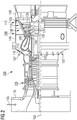
- FIG. 2 shows an embodiment of a gas turbine, as it can be used in a gas turbine plant according to the invention, in a longitudinal partial section.
- the gas turbine 100 has inside a rotatably mounted about a rotation axis 102 rotor 103 with a shaft 101, which is also referred to as a turbine runner.
- an intake housing 104 a compressor 105, for example, a toroidal combustion chamber 110, in particular annular combustion chamber, with a plurality of coaxially arranged burners 107, a turbine 108 and the exhaust housing 109th
- a compressor 105 for example, a toroidal combustion chamber 110, in particular annular combustion chamber, with a plurality of coaxially arranged burners 107, a turbine 108 and the exhaust housing 109th
- the hot gas relaxes in an annular hot gas passage 111 of the turbine.
- the turbine stages 112 connected in series form the turbine 108.
- Each turbine stage 112 is formed, for example, from two blade rings. Viewed in the flow direction of a working medium 113 follows in the hot gas channel 111 of a row of vanes 115 formed from 120 blades row 125.
- the blades 120 usually represent those components with the largest load, the load of the blades 120 in the flow direction of the working fluid 113 due to the rising radii of the Device increases. These components therefore significantly determine the power limit.
- the vanes 130 are secured to an inner shell 138 of a stator 143, whereas the vanes 120 of a row 125 are mounted to the rotor 103 by means of a turbine disk 133, for example. Coupled to the rotor 103 is an electric generator (not shown).
- air 105 is sucked in and compressed by the compressor 105 through the intake housing 104.
- the compressed air provided at the turbine-side end of the compressor 105 is supplied to the burners 107 where it is mixed with a fuel.
- the mixture is then burned to form the working fluid 113 in the combustion chamber 110.
- the working medium 113 flows along the hot gas channel 111 past the guide vanes 130 and the rotor blades 120.
- the working medium 113 expands in a pulse-transmitting manner, so that the rotor blades 120 drive the rotor 103 and this drives the machine coupled to it.
- the components exposed to the hot working medium 113 are subject to thermal loads during operation of the gas turbine 100.
- the guide vanes 130 and rotor blades 120 seen in the flow direction of the working medium 113 first Turbine stage 112 is most thermally stressed in addition to the heat shield elements lining the annular combustor 110.
- the vane 130 has a guide vane foot (not shown here) facing the inner housing 138 of the turbine 108 and a vane head opposite the vane foot.
- the vane head faces the rotor 103 and fixed to a mounting ring 140 of the stator 143.
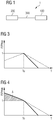
- FIG. 3 shows a first diagram that illustrates the performance of a gas turbine as a function of temperature, as it is known from the prior art.
- the electrical output of the gas turbine plant is plotted as a solid line and the turbine power of the gas turbine as a dashed line above the ambient temperature T, wherein the two said services are normalized to their respective limit power value.
- the gas turbine plant is in the example of FIG. 3 operated according to the conventional procedure. It turns out that for high temperatures due to the reduced density of the ambient air and the resulting reduced mass flow of the compressor of the gas turbine, the electrical output of the gas turbine plant remains below the set limit and continues to decrease with increasing ambient temperature.
- the turbine power of the gas turbine which determines the actual load of the turbine section of the gas turbine, shows a corresponding behavior. With decreasing ambient temperatures, the air drawn in by the compressor becomes more dense so that the gas turbine can be provided by the compressor with a larger mass flow, which causes correspondingly increasing turbine power and also electrical output power.
- the electrical output reaches a predetermined maximum value, which in the example shown occurs at an ambient temperature T 0 , it is limited and kept as close as possible to the maximum value, which is due to control interventions can happen on the compressor.
- the turbine power of the gas turbine also reaches its maximum permissible value.
- the electrical output power is kept constant, however, the gas turbine can achieve this electrical output at ever lower turbine engine turbine power. This is explained by the fact that the rotational energy taken from the hot gas stream of the combusting fuel from the turbine section is again partly released to the compressor, which compresses the combustion air.
- the gas turbine can provide this electrical output with decreasing turbine power as the ambient temperature decreases. Accordingly, the load of the gas turbine with low temperatures falls below the maximum permissible level.
- FIG. 4 shows a second diagram that illustrates the performance of a gas turbine as a function of temperature.
- the electrical output of the gas turbine plant are plotted as a solid line and the turbine power of the gas turbine as a dashed line above the ambient temperature T.
- the behavior above the ambient temperature T 0 corresponds to that of FIG. 3 , so that a repetition of the above explanations can be omitted.
- the gas turbine is now controlled so that the power limit is determined depending on the prevailing operating conditions. The aim here is to keep the turbine output as a controlled variable at its maximum permissible value.
Landscapes
- Engineering & Computer Science (AREA)
- Chemical & Material Sciences (AREA)
- Combustion & Propulsion (AREA)
- Mechanical Engineering (AREA)
- General Engineering & Computer Science (AREA)
- Physics & Mathematics (AREA)
- Fluid Mechanics (AREA)
- Control Of Eletrric Generators (AREA)
Claims (9)
- Procédé pour faire fonctionner une installation (1) de turbine à gaz comprenant une turbine (100) à gaz et une génératrice (200) électrique entraînée par la turbine (100) à gaz, le procédé ayant au moins les stades suivants :- détection d'une puissance instantanée de l'installation (1) de turbine à gaz;- comparaison de la puissance instantanée détectée à une valeur limite de puissance; et- limitation de la puissance instantanée, si la comparaison indique que la puissance instantanée détectée atteint ou dépasse la valeur limite de puissance,comprenant un stade de détection d'au moins un paramètre de fonctionnement de l'installation (1) de turbine à gaz et un stade de détermination de la valeur limite de puissance en fonction du au moins un paramètre de fonctionnement détecté,
caractérisé en ce que
le au moins un paramètre de fonctionnement de l'installation (1) de turbine à gaz comprend une pression de l'atmosphère ambiante et on augmente la valeur limite de la puissance, si la pression de l'atmosphère ambiante augmente. - Procédé suivant la revendication précédente, dans lequel le au moins un paramètre de fonctionnement de l'installation (1) de turbine à gaz comprend en outre un paramètre de fonctionnement sélectionné parmi une température de l'atmosphère ambiante, un temps de marche total de la turbine (100) à gaz ou une production totale d'énergie de l'installation (1) de turbine à gaz.
- Procédé suivant la revendication précédente 2, dans lequel on augmente la valeur limite de la puissance, si la température de l'atmosphère ambiante s'abaisse.
- Procédé suivant l'une des revendications 2 à 3, dans lequel on diminue la valeur limite de la puissance, si le temps de marche totale de la turbine (100) à gaz dépasse une valeur de seuil définie à l'avance.
- Procédé suivant l'une des revendications précédentes, dans lequel on définie la puissance instantanée de l'installation (1) de turbine à gaz en déterminant une puissance électrique de sortie de la génératrice (200) électrique de l'installation (1) de la turbine à gaz.
- Procédé suivant l'une des revendications 1 à 4, dans lequel on détermine la puissance instantanée de l'installation (1) de turbine à gaz en déterminant la puissance instantanée de la turbine (100) à gaz de l'installation (1) de turbine à gaz.
- Procédé suivant l'une des revendications précédentes, dans lequel on limite la puissance instantanée en limitant le courant massique d'un compresseur (105) de la turbine (100) à gaz.
- Installation (1) de turbine à gaz, comprenant une turbine (100) à gaz, une génératrice (200) électrique reliée à la turbine (100) à gaz et une unité de commande reliée à la turbine (100) à gaz et à la génératrice (200) électrique, est constituée pour effectuer le procédé de l'une des revendications précédentes.
- Support de données déchiffrables par ordinateur comprenant un code de programme pouvant être exécuté par un ordinateur, qui, réalisé par une unité de commande des installations (1) de turbine à gaz suivant la revendication précédente, effectue le procédé suivant l'une des revendications 1 à 7.
Priority Applications (1)
| Application Number | Priority Date | Filing Date | Title |
|---|---|---|---|
| EP15708484.9A EP3097293B1 (fr) | 2014-03-20 | 2015-03-03 | Régulation de puissance limite variable pour turbines à gaz |
Applications Claiming Priority (3)
| Application Number | Priority Date | Filing Date | Title |
|---|---|---|---|
| EP14160875.2A EP2921673A1 (fr) | 2014-03-20 | 2014-03-20 | Régulation de puissance limite variable pour turbines à gaz |
| EP15708484.9A EP3097293B1 (fr) | 2014-03-20 | 2015-03-03 | Régulation de puissance limite variable pour turbines à gaz |
| PCT/EP2015/054420 WO2015139949A1 (fr) | 2014-03-20 | 2015-03-03 | Régulation variable de la puissance limite de turbines à gaz |
Publications (2)
| Publication Number | Publication Date |
|---|---|
| EP3097293A1 EP3097293A1 (fr) | 2016-11-30 |
| EP3097293B1 true EP3097293B1 (fr) | 2018-12-12 |
Family
ID=50336162
Family Applications (2)
| Application Number | Title | Priority Date | Filing Date |
|---|---|---|---|
| EP14160875.2A Withdrawn EP2921673A1 (fr) | 2014-03-20 | 2014-03-20 | Régulation de puissance limite variable pour turbines à gaz |
| EP15708484.9A Not-in-force EP3097293B1 (fr) | 2014-03-20 | 2015-03-03 | Régulation de puissance limite variable pour turbines à gaz |
Family Applications Before (1)
| Application Number | Title | Priority Date | Filing Date |
|---|---|---|---|
| EP14160875.2A Withdrawn EP2921673A1 (fr) | 2014-03-20 | 2014-03-20 | Régulation de puissance limite variable pour turbines à gaz |
Country Status (6)
| Country | Link |
|---|---|
| US (1) | US10077718B2 (fr) |
| EP (2) | EP2921673A1 (fr) |
| CN (1) | CN106164445B (fr) |
| CA (1) | CA2942974C (fr) |
| RU (1) | RU2640874C1 (fr) |
| WO (1) | WO2015139949A1 (fr) |
Families Citing this family (3)
| Publication number | Priority date | Publication date | Assignee | Title |
|---|---|---|---|---|
| US10683099B2 (en) * | 2017-02-08 | 2020-06-16 | Pratt & Whitney Canada Corp. | Methods and systems for controlling operation of aircraft engines |
| CN110848025A (zh) * | 2019-11-12 | 2020-02-28 | 广东第二师范学院 | 基于可变模糊隶属度智能自检的燃气轮机及其检测分析方法 |
| CN112903301B (zh) * | 2019-12-04 | 2023-09-15 | 西门子能源国际公司 | 识别燃气轮机运行状态的方法和装置 |
Citations (1)
| Publication number | Priority date | Publication date | Assignee | Title |
|---|---|---|---|---|
| EP1085267A2 (fr) * | 1999-09-20 | 2001-03-21 | ABB (Schweiz) AG | Régulation des mesures primaires pour la réduction des oxydes d'azote dans des turbines à gaz |
Family Cites Families (19)
| Publication number | Priority date | Publication date | Assignee | Title |
|---|---|---|---|---|
| US6164057A (en) * | 1999-03-16 | 2000-12-26 | General Electric Co. | Gas turbine generator having reserve capacity controller |
| US6718771B1 (en) * | 1999-09-03 | 2004-04-13 | Enhanced Turbine Output Holding Llc | Gas turbine operative at high ambient temperatures |
| WO2002084091A1 (fr) * | 2001-04-09 | 2002-10-24 | Hitachi, Ltd. | Générateur de puissance à turbine à gaz |
| US6871160B2 (en) * | 2001-09-08 | 2005-03-22 | Scientific Monitoring Inc. | Intelligent condition-based engine/equipment management system |
| WO2003058047A1 (fr) * | 2002-01-07 | 2003-07-17 | Alstom Technology Ltd | Mode de fonctionnement d'un groupe a turbine a gaz |
| JP4495971B2 (ja) * | 2002-01-25 | 2010-07-07 | アルストム テクノロジー リミテッド | ガスタービン群を運転するための方法 |
| US7146795B2 (en) * | 2002-06-10 | 2006-12-12 | Rgp Engineering Llc | System and method for producing injection-quality steam for combustion turbine power augmentation |
| US6837056B2 (en) * | 2002-12-19 | 2005-01-04 | General Electric Company | Turbine inlet air-cooling system and method |
| DE102004005476A1 (de) * | 2003-02-11 | 2004-12-09 | Alstom Technology Ltd | Verfahren zum Betrieb einer Gasturbogruppe |
| EP1592870B1 (fr) | 2003-02-11 | 2015-06-24 | Alstom Technology Ltd | Procede pour faire fonctionner un ensemble turbine a gaz |
| RU2334889C2 (ru) | 2006-07-27 | 2008-09-27 | Открытое акционерное общество "СТАР" | Способ управления расходом топлива в турбовинтовую силовую установку |
| US9043118B2 (en) * | 2007-04-02 | 2015-05-26 | General Electric Company | Methods and systems for model-based control of gas turbines |
| ATE497094T1 (de) | 2008-05-26 | 2011-02-15 | Siemens Ag | Verfahren zum betreiben einer gasturbine |
| IT1396516B1 (it) | 2009-11-27 | 2012-12-14 | Nuovo Pignone Spa | Metodo di controllo di modo basato su temperatura di scarico per turbina a gas e turbina a gas |
| IT1396514B1 (it) | 2009-11-27 | 2012-12-14 | Nuovo Pignone Spa | Metodo di controllo di turbina basato su rapporto tra temperatura di scarico e pressione di turbina |
| US20110210555A1 (en) * | 2010-02-26 | 2011-09-01 | Xia Jian Y | Gas turbine driven electric power system with constant output through a full range of ambient conditions |
| US9970360B2 (en) * | 2012-03-05 | 2018-05-15 | Siemens Aktiengesellschaft | Gas turbine engine configured to shape power output |
| US9255525B2 (en) * | 2012-11-30 | 2016-02-09 | General Electric Company | System and method for gas turbine operation |
| US8910531B1 (en) * | 2013-07-03 | 2014-12-16 | General Electric Company | System for determining target misalignment in turbine shaft and related method |
-
2014
- 2014-03-20 EP EP14160875.2A patent/EP2921673A1/fr not_active Withdrawn
-
2015
- 2015-03-03 WO PCT/EP2015/054420 patent/WO2015139949A1/fr active Application Filing
- 2015-03-03 CA CA2942974A patent/CA2942974C/fr not_active Expired - Fee Related
- 2015-03-03 US US15/125,417 patent/US10077718B2/en not_active Expired - Fee Related
- 2015-03-03 CN CN201580014933.9A patent/CN106164445B/zh not_active Expired - Fee Related
- 2015-03-03 EP EP15708484.9A patent/EP3097293B1/fr not_active Not-in-force
- 2015-03-03 RU RU2016141230A patent/RU2640874C1/ru not_active IP Right Cessation
Patent Citations (1)
| Publication number | Priority date | Publication date | Assignee | Title |
|---|---|---|---|---|
| EP1085267A2 (fr) * | 1999-09-20 | 2001-03-21 | ABB (Schweiz) AG | Régulation des mesures primaires pour la réduction des oxydes d'azote dans des turbines à gaz |
Also Published As
| Publication number | Publication date |
|---|---|
| CN106164445B (zh) | 2018-11-02 |
| CN106164445A (zh) | 2016-11-23 |
| US20170107912A1 (en) | 2017-04-20 |
| US10077718B2 (en) | 2018-09-18 |
| EP3097293A1 (fr) | 2016-11-30 |
| WO2015139949A1 (fr) | 2015-09-24 |
| EP2921673A1 (fr) | 2015-09-23 |
| CA2942974A1 (fr) | 2015-09-24 |
| RU2640874C1 (ru) | 2018-01-12 |
| CA2942974C (fr) | 2018-08-21 |
Similar Documents
| Publication | Publication Date | Title |
|---|---|---|
| EP2260193B1 (fr) | Procédé de régulation d'une turbine à gaz dans une centrale électrique et centrale électrique destinée à mettre en application le procédé | |
| DE102010016708B4 (de) | Verfahren im Zusammenhang mit der Steuerung und dem Betrieb einer Gasturbine | |
| EP1711690B1 (fr) | Turbine a gaz, notamment groupe motopropulseur | |
| DE102011055823A1 (de) | System und Verfahren zum Betreiben eines Verdichters | |
| EP2407652A1 (fr) | Turbine à gaz dotée d'un système d'aération secondaire et procédé de fonctionnement d'une telle turbine à gaz | |
| EP3097293B1 (fr) | Régulation de puissance limite variable pour turbines à gaz | |
| DE112015000664T5 (de) | Gasturbinen-Steuerungsvorrichtung, Gasturbine, und Gasturbinen-Steuerungsverfahren | |
| DE102009043833A1 (de) | Relativpositionierung von Turbinenschaufelblättern | |
| EP2128406A1 (fr) | Procédé destiné à l'operation d'une turbine à gaz | |
| DE102009059224A1 (de) | Gegenstrom-Hochdruck-Niederdruck-Dampfturbine | |
| DE112018005376T5 (de) | Rotierende-maschinen-steuervorrichtung, rotierende-maschinen-ausrüstung, rotierende-maschinen-steuerverfahren und rotierende maschinen-steuerprogramm | |
| EP2365197B1 (fr) | Refroidissement accéléré d'une turbine à gaz | |
| DE102008002610A1 (de) | Verfahren zur (Online-) Betriebsüberwachung und Regelung einer Gasturbinenanlage | |
| EP2946096B1 (fr) | Procédé de fonctionnement d'une turbine à gaz en dessous de sa puissance nominale | |
| EP1462633B1 (fr) | Procédé de réglage de la température de gaz chaud d'une turbine à gaz | |
| EP2619461B1 (fr) | Dispositif et procédé pour l'utilisation en sécurité d'un compresseur à la limite de pompage | |
| EP3071818B1 (fr) | Fonctionnement d'une installation de turbine à gaz comprenant un compresseur et une turbine | |
| EP2805026B1 (fr) | Système de turbines comprenant trois turbines couplées à une transmission centrale et procédé permettant de faire fonctionner une machine de travail | |
| EP2971652B1 (fr) | Mis à disposition d'alimentation électrique négative par turbine a gaz | |
| EP2896806A1 (fr) | Modification d'une puissance utile d'une installation de turbine à gaz | |
| EP2907988A1 (fr) | Procédé de fonctionnement d'une chaîne de compresseur et chaîne de compresseur | |
| EP3071799B1 (fr) | Procédé d'analyse et turbine à gaz | |
| EP3144540B1 (fr) | Étage de compresseur de turbine à gaz | |
| DE102014203318A1 (de) | Verfahren zum Betrieb einer Gasturbine bei aktiver hydraulischer Spalteinstellung | |
| EP2964930B1 (fr) | Procédé de réduction des émissions de co d'une turbine à gaz et turbine à gaz |
Legal Events
| Date | Code | Title | Description |
|---|---|---|---|
| PUAI | Public reference made under article 153(3) epc to a published international application that has entered the european phase |
Free format text: ORIGINAL CODE: 0009012 |
|
| 17P | Request for examination filed |
Effective date: 20160825 |
|
| AK | Designated contracting states |
Kind code of ref document: A1 Designated state(s): AL AT BE BG CH CY CZ DE DK EE ES FI FR GB GR HR HU IE IS IT LI LT LU LV MC MK MT NL NO PL PT RO RS SE SI SK SM TR |
|
| AX | Request for extension of the european patent |
Extension state: BA ME |
|
| RIN1 | Information on inventor provided before grant (corrected) |
Inventor name: KREUTZER, PHILIPP Inventor name: SCHAEFER, MARC Inventor name: KERSTIENS, THOMAS Inventor name: SCHNEIDER, OLIVER Inventor name: MUEHLHOELZER, ROSA-EOS Inventor name: STAPPER, MARTIN Inventor name: BEILER, JAN-DIRK Inventor name: GAMM, HANS-GEORG Inventor name: REINBERG, MARC Inventor name: LARSON, MARCO Inventor name: PURPS, FLORIAN |
|
| DAV | Request for validation of the european patent (deleted) | ||
| DAX | Request for extension of the european patent (deleted) | ||
| RAP1 | Party data changed (applicant data changed or rights of an application transferred) |
Owner name: SIEMENS AKTIENGESELLSCHAFT |
|
| GRAP | Despatch of communication of intention to grant a patent |
Free format text: ORIGINAL CODE: EPIDOSNIGR1 |
|
| STAA | Information on the status of an ep patent application or granted ep patent |
Free format text: STATUS: GRANT OF PATENT IS INTENDED |
|
| INTG | Intention to grant announced |
Effective date: 20180725 |
|
| GRAS | Grant fee paid |
Free format text: ORIGINAL CODE: EPIDOSNIGR3 |
|
| GRAA | (expected) grant |
Free format text: ORIGINAL CODE: 0009210 |
|
| STAA | Information on the status of an ep patent application or granted ep patent |
Free format text: STATUS: THE PATENT HAS BEEN GRANTED |
|
| AK | Designated contracting states |
Kind code of ref document: B1 Designated state(s): AL AT BE BG CH CY CZ DE DK EE ES FI FR GB GR HR HU IE IS IT LI LT LU LV MC MK MT NL NO PL PT RO RS SE SI SK SM TR |
|
| REG | Reference to a national code |
Ref country code: GB Ref legal event code: FG4D Free format text: NOT ENGLISH |
|
| REG | Reference to a national code |
Ref country code: CH Ref legal event code: EP |
|
| REG | Reference to a national code |
Ref country code: AT Ref legal event code: REF Ref document number: 1076311 Country of ref document: AT Kind code of ref document: T Effective date: 20181215 |
|
| REG | Reference to a national code |
Ref country code: DE Ref legal event code: R096 Ref document number: 502015007187 Country of ref document: DE |
|
| REG | Reference to a national code |
Ref country code: IE Ref legal event code: FG4D Free format text: LANGUAGE OF EP DOCUMENT: GERMAN |
|
| REG | Reference to a national code |
Ref country code: NL Ref legal event code: MP Effective date: 20181212 |
|
| REG | Reference to a national code |
Ref country code: LT Ref legal event code: MG4D |
|
| PG25 | Lapsed in a contracting state [announced via postgrant information from national office to epo] |
Ref country code: ES Free format text: LAPSE BECAUSE OF FAILURE TO SUBMIT A TRANSLATION OF THE DESCRIPTION OR TO PAY THE FEE WITHIN THE PRESCRIBED TIME-LIMIT Effective date: 20181212 Ref country code: LT Free format text: LAPSE BECAUSE OF FAILURE TO SUBMIT A TRANSLATION OF THE DESCRIPTION OR TO PAY THE FEE WITHIN THE PRESCRIBED TIME-LIMIT Effective date: 20181212 Ref country code: BG Free format text: LAPSE BECAUSE OF FAILURE TO SUBMIT A TRANSLATION OF THE DESCRIPTION OR TO PAY THE FEE WITHIN THE PRESCRIBED TIME-LIMIT Effective date: 20190312 Ref country code: HR Free format text: LAPSE BECAUSE OF FAILURE TO SUBMIT A TRANSLATION OF THE DESCRIPTION OR TO PAY THE FEE WITHIN THE PRESCRIBED TIME-LIMIT Effective date: 20181212 Ref country code: LV Free format text: LAPSE BECAUSE OF FAILURE TO SUBMIT A TRANSLATION OF THE DESCRIPTION OR TO PAY THE FEE WITHIN THE PRESCRIBED TIME-LIMIT Effective date: 20181212 Ref country code: NO Free format text: LAPSE BECAUSE OF FAILURE TO SUBMIT A TRANSLATION OF THE DESCRIPTION OR TO PAY THE FEE WITHIN THE PRESCRIBED TIME-LIMIT Effective date: 20190312 Ref country code: FI Free format text: LAPSE BECAUSE OF FAILURE TO SUBMIT A TRANSLATION OF THE DESCRIPTION OR TO PAY THE FEE WITHIN THE PRESCRIBED TIME-LIMIT Effective date: 20181212 |
|
| PG25 | Lapsed in a contracting state [announced via postgrant information from national office to epo] |
Ref country code: AL Free format text: LAPSE BECAUSE OF FAILURE TO SUBMIT A TRANSLATION OF THE DESCRIPTION OR TO PAY THE FEE WITHIN THE PRESCRIBED TIME-LIMIT Effective date: 20181212 Ref country code: SE Free format text: LAPSE BECAUSE OF FAILURE TO SUBMIT A TRANSLATION OF THE DESCRIPTION OR TO PAY THE FEE WITHIN THE PRESCRIBED TIME-LIMIT Effective date: 20181212 Ref country code: RS Free format text: LAPSE BECAUSE OF FAILURE TO SUBMIT A TRANSLATION OF THE DESCRIPTION OR TO PAY THE FEE WITHIN THE PRESCRIBED TIME-LIMIT Effective date: 20181212 Ref country code: GR Free format text: LAPSE BECAUSE OF FAILURE TO SUBMIT A TRANSLATION OF THE DESCRIPTION OR TO PAY THE FEE WITHIN THE PRESCRIBED TIME-LIMIT Effective date: 20190313 |
|
| PG25 | Lapsed in a contracting state [announced via postgrant information from national office to epo] |
Ref country code: NL Free format text: LAPSE BECAUSE OF FAILURE TO SUBMIT A TRANSLATION OF THE DESCRIPTION OR TO PAY THE FEE WITHIN THE PRESCRIBED TIME-LIMIT Effective date: 20181212 |
|
| PG25 | Lapsed in a contracting state [announced via postgrant information from national office to epo] |
Ref country code: CZ Free format text: LAPSE BECAUSE OF FAILURE TO SUBMIT A TRANSLATION OF THE DESCRIPTION OR TO PAY THE FEE WITHIN THE PRESCRIBED TIME-LIMIT Effective date: 20181212 Ref country code: PT Free format text: LAPSE BECAUSE OF FAILURE TO SUBMIT A TRANSLATION OF THE DESCRIPTION OR TO PAY THE FEE WITHIN THE PRESCRIBED TIME-LIMIT Effective date: 20190412 Ref country code: IT Free format text: LAPSE BECAUSE OF FAILURE TO SUBMIT A TRANSLATION OF THE DESCRIPTION OR TO PAY THE FEE WITHIN THE PRESCRIBED TIME-LIMIT Effective date: 20181212 Ref country code: PL Free format text: LAPSE BECAUSE OF FAILURE TO SUBMIT A TRANSLATION OF THE DESCRIPTION OR TO PAY THE FEE WITHIN THE PRESCRIBED TIME-LIMIT Effective date: 20181212 |
|
| PG25 | Lapsed in a contracting state [announced via postgrant information from national office to epo] |
Ref country code: EE Free format text: LAPSE BECAUSE OF FAILURE TO SUBMIT A TRANSLATION OF THE DESCRIPTION OR TO PAY THE FEE WITHIN THE PRESCRIBED TIME-LIMIT Effective date: 20181212 Ref country code: SK Free format text: LAPSE BECAUSE OF FAILURE TO SUBMIT A TRANSLATION OF THE DESCRIPTION OR TO PAY THE FEE WITHIN THE PRESCRIBED TIME-LIMIT Effective date: 20181212 Ref country code: RO Free format text: LAPSE BECAUSE OF FAILURE TO SUBMIT A TRANSLATION OF THE DESCRIPTION OR TO PAY THE FEE WITHIN THE PRESCRIBED TIME-LIMIT Effective date: 20181212 Ref country code: IS Free format text: LAPSE BECAUSE OF FAILURE TO SUBMIT A TRANSLATION OF THE DESCRIPTION OR TO PAY THE FEE WITHIN THE PRESCRIBED TIME-LIMIT Effective date: 20190412 Ref country code: SM Free format text: LAPSE BECAUSE OF FAILURE TO SUBMIT A TRANSLATION OF THE DESCRIPTION OR TO PAY THE FEE WITHIN THE PRESCRIBED TIME-LIMIT Effective date: 20181212 |
|
| REG | Reference to a national code |
Ref country code: DE Ref legal event code: R097 Ref document number: 502015007187 Country of ref document: DE |
|
| REG | Reference to a national code |
Ref country code: DE Ref legal event code: R119 Ref document number: 502015007187 Country of ref document: DE |
|
| PLBE | No opposition filed within time limit |
Free format text: ORIGINAL CODE: 0009261 |
|
| STAA | Information on the status of an ep patent application or granted ep patent |
Free format text: STATUS: NO OPPOSITION FILED WITHIN TIME LIMIT |
|
| PG25 | Lapsed in a contracting state [announced via postgrant information from national office to epo] |
Ref country code: DK Free format text: LAPSE BECAUSE OF FAILURE TO SUBMIT A TRANSLATION OF THE DESCRIPTION OR TO PAY THE FEE WITHIN THE PRESCRIBED TIME-LIMIT Effective date: 20181212 Ref country code: SI Free format text: LAPSE BECAUSE OF FAILURE TO SUBMIT A TRANSLATION OF THE DESCRIPTION OR TO PAY THE FEE WITHIN THE PRESCRIBED TIME-LIMIT Effective date: 20181212 Ref country code: MC Free format text: LAPSE BECAUSE OF FAILURE TO SUBMIT A TRANSLATION OF THE DESCRIPTION OR TO PAY THE FEE WITHIN THE PRESCRIBED TIME-LIMIT Effective date: 20181212 |
|
| REG | Reference to a national code |
Ref country code: CH Ref legal event code: PL |
|
| 26N | No opposition filed |
Effective date: 20190913 |
|
| GBPC | Gb: european patent ceased through non-payment of renewal fee |
Effective date: 20190312 |
|
| PG25 | Lapsed in a contracting state [announced via postgrant information from national office to epo] |
Ref country code: LU Free format text: LAPSE BECAUSE OF NON-PAYMENT OF DUE FEES Effective date: 20190303 |
|
| REG | Reference to a national code |
Ref country code: BE Ref legal event code: MM Effective date: 20190331 |
|
| PG25 | Lapsed in a contracting state [announced via postgrant information from national office to epo] |
Ref country code: GB Free format text: LAPSE BECAUSE OF NON-PAYMENT OF DUE FEES Effective date: 20190312 Ref country code: DE Free format text: LAPSE BECAUSE OF NON-PAYMENT OF DUE FEES Effective date: 20191001 Ref country code: CH Free format text: LAPSE BECAUSE OF NON-PAYMENT OF DUE FEES Effective date: 20190331 Ref country code: LI Free format text: LAPSE BECAUSE OF NON-PAYMENT OF DUE FEES Effective date: 20190331 Ref country code: IE Free format text: LAPSE BECAUSE OF NON-PAYMENT OF DUE FEES Effective date: 20190303 |
|
| PG25 | Lapsed in a contracting state [announced via postgrant information from national office to epo] |
Ref country code: FR Free format text: LAPSE BECAUSE OF NON-PAYMENT OF DUE FEES Effective date: 20190331 Ref country code: BE Free format text: LAPSE BECAUSE OF NON-PAYMENT OF DUE FEES Effective date: 20190331 |
|
| PG25 | Lapsed in a contracting state [announced via postgrant information from national office to epo] |
Ref country code: TR Free format text: LAPSE BECAUSE OF FAILURE TO SUBMIT A TRANSLATION OF THE DESCRIPTION OR TO PAY THE FEE WITHIN THE PRESCRIBED TIME-LIMIT Effective date: 20181212 |
|
| PG25 | Lapsed in a contracting state [announced via postgrant information from national office to epo] |
Ref country code: MT Free format text: LAPSE BECAUSE OF FAILURE TO SUBMIT A TRANSLATION OF THE DESCRIPTION OR TO PAY THE FEE WITHIN THE PRESCRIBED TIME-LIMIT Effective date: 20181212 |
|
| REG | Reference to a national code |
Ref country code: AT Ref legal event code: MM01 Ref document number: 1076311 Country of ref document: AT Kind code of ref document: T Effective date: 20200303 |
|
| PG25 | Lapsed in a contracting state [announced via postgrant information from national office to epo] |
Ref country code: CY Free format text: LAPSE BECAUSE OF FAILURE TO SUBMIT A TRANSLATION OF THE DESCRIPTION OR TO PAY THE FEE WITHIN THE PRESCRIBED TIME-LIMIT Effective date: 20181212 |
|
| PG25 | Lapsed in a contracting state [announced via postgrant information from national office to epo] |
Ref country code: HU Free format text: LAPSE BECAUSE OF FAILURE TO SUBMIT A TRANSLATION OF THE DESCRIPTION OR TO PAY THE FEE WITHIN THE PRESCRIBED TIME-LIMIT; INVALID AB INITIO Effective date: 20150303 |
|
| PG25 | Lapsed in a contracting state [announced via postgrant information from national office to epo] |
Ref country code: AT Free format text: LAPSE BECAUSE OF NON-PAYMENT OF DUE FEES Effective date: 20200303 |
|
| PG25 | Lapsed in a contracting state [announced via postgrant information from national office to epo] |
Ref country code: MK Free format text: LAPSE BECAUSE OF FAILURE TO SUBMIT A TRANSLATION OF THE DESCRIPTION OR TO PAY THE FEE WITHIN THE PRESCRIBED TIME-LIMIT Effective date: 20181212 |