EP3096830B1 - Wiedereintrittskatheter mit zusammenklappbarer spitze - Google Patents
Wiedereintrittskatheter mit zusammenklappbarer spitze Download PDFInfo
- Publication number
- EP3096830B1 EP3096830B1 EP15737506.4A EP15737506A EP3096830B1 EP 3096830 B1 EP3096830 B1 EP 3096830B1 EP 15737506 A EP15737506 A EP 15737506A EP 3096830 B1 EP3096830 B1 EP 3096830B1
- Authority
- EP
- European Patent Office
- Prior art keywords
- catheter
- port
- distal portion
- wire
- distal
- Prior art date
- Legal status (The legal status is an assumption and is not a legal conclusion. Google has not performed a legal analysis and makes no representation as to the accuracy of the status listed.)
- Active
Links
Images


Classifications
-
- A—HUMAN NECESSITIES
- A61—MEDICAL OR VETERINARY SCIENCE; HYGIENE
- A61M—DEVICES FOR INTRODUCING MEDIA INTO, OR ONTO, THE BODY; DEVICES FOR TRANSDUCING BODY MEDIA OR FOR TAKING MEDIA FROM THE BODY; DEVICES FOR PRODUCING OR ENDING SLEEP OR STUPOR
- A61M25/00—Catheters; Hollow probes
- A61M25/0067—Catheters; Hollow probes characterised by the distal end, e.g. tips
- A61M25/008—Strength or flexibility characteristics of the catheter tip
-
- A—HUMAN NECESSITIES
- A61—MEDICAL OR VETERINARY SCIENCE; HYGIENE
- A61B—DIAGNOSIS; SURGERY; IDENTIFICATION
- A61B17/00—Surgical instruments, devices or methods
- A61B17/32—Surgical cutting instruments
- A61B17/3205—Excision instruments
- A61B17/3207—Atherectomy devices working by cutting or abrading; Similar devices specially adapted for non-vascular obstructions
- A61B17/320783—Atherectomy devices working by cutting or abrading; Similar devices specially adapted for non-vascular obstructions through side-hole, e.g. sliding or rotating cutter inside catheter
-
- A—HUMAN NECESSITIES
- A61—MEDICAL OR VETERINARY SCIENCE; HYGIENE
- A61F—FILTERS IMPLANTABLE INTO BLOOD VESSELS; PROSTHESES; DEVICES PROVIDING PATENCY TO, OR PREVENTING COLLAPSING OF, TUBULAR STRUCTURES OF THE BODY, e.g. STENTS; ORTHOPAEDIC, NURSING OR CONTRACEPTIVE DEVICES; FOMENTATION; TREATMENT OR PROTECTION OF EYES OR EARS; BANDAGES, DRESSINGS OR ABSORBENT PADS; FIRST-AID KITS
- A61F2/00—Filters implantable into blood vessels; Prostheses, i.e. artificial substitutes or replacements for parts of the body; Appliances for connecting them with the body; Devices providing patency to, or preventing collapsing of, tubular structures of the body, e.g. stents
- A61F2/82—Devices providing patency to, or preventing collapsing of, tubular structures of the body, e.g. stents
- A61F2/844—Devices providing patency to, or preventing collapsing of, tubular structures of the body, e.g. stents folded prior to deployment
-
- A—HUMAN NECESSITIES
- A61—MEDICAL OR VETERINARY SCIENCE; HYGIENE
- A61L—METHODS OR APPARATUS FOR STERILISING MATERIALS OR OBJECTS IN GENERAL; DISINFECTION, STERILISATION OR DEODORISATION OF AIR; CHEMICAL ASPECTS OF BANDAGES, DRESSINGS, ABSORBENT PADS OR SURGICAL ARTICLES; MATERIALS FOR BANDAGES, DRESSINGS, ABSORBENT PADS OR SURGICAL ARTICLES
- A61L29/00—Materials for catheters, medical tubing, cannulae, or endoscopes or for coating catheters
- A61L29/04—Macromolecular materials
- A61L29/06—Macromolecular materials obtained otherwise than by reactions only involving carbon-to-carbon unsaturated bonds
-
- A—HUMAN NECESSITIES
- A61—MEDICAL OR VETERINARY SCIENCE; HYGIENE
- A61L—METHODS OR APPARATUS FOR STERILISING MATERIALS OR OBJECTS IN GENERAL; DISINFECTION, STERILISATION OR DEODORISATION OF AIR; CHEMICAL ASPECTS OF BANDAGES, DRESSINGS, ABSORBENT PADS OR SURGICAL ARTICLES; MATERIALS FOR BANDAGES, DRESSINGS, ABSORBENT PADS OR SURGICAL ARTICLES
- A61L29/00—Materials for catheters, medical tubing, cannulae, or endoscopes or for coating catheters
- A61L29/14—Materials characterised by their function or physical properties, e.g. lubricating compositions
-
- A—HUMAN NECESSITIES
- A61—MEDICAL OR VETERINARY SCIENCE; HYGIENE
- A61M—DEVICES FOR INTRODUCING MEDIA INTO, OR ONTO, THE BODY; DEVICES FOR TRANSDUCING BODY MEDIA OR FOR TAKING MEDIA FROM THE BODY; DEVICES FOR PRODUCING OR ENDING SLEEP OR STUPOR
- A61M25/00—Catheters; Hollow probes
- A61M25/0021—Catheters; Hollow probes characterised by the form of the tubing
-
- A—HUMAN NECESSITIES
- A61—MEDICAL OR VETERINARY SCIENCE; HYGIENE
- A61M—DEVICES FOR INTRODUCING MEDIA INTO, OR ONTO, THE BODY; DEVICES FOR TRANSDUCING BODY MEDIA OR FOR TAKING MEDIA FROM THE BODY; DEVICES FOR PRODUCING OR ENDING SLEEP OR STUPOR
- A61M25/00—Catheters; Hollow probes
- A61M25/0043—Catheters; Hollow probes characterised by structural features
- A61M25/005—Catheters; Hollow probes characterised by structural features with embedded materials for reinforcement, e.g. wires, coils, braids
-
- A—HUMAN NECESSITIES
- A61—MEDICAL OR VETERINARY SCIENCE; HYGIENE
- A61M—DEVICES FOR INTRODUCING MEDIA INTO, OR ONTO, THE BODY; DEVICES FOR TRANSDUCING BODY MEDIA OR FOR TAKING MEDIA FROM THE BODY; DEVICES FOR PRODUCING OR ENDING SLEEP OR STUPOR
- A61M25/00—Catheters; Hollow probes
- A61M25/0043—Catheters; Hollow probes characterised by structural features
- A61M25/0054—Catheters; Hollow probes characterised by structural features with regions for increasing flexibility
-
- A—HUMAN NECESSITIES
- A61—MEDICAL OR VETERINARY SCIENCE; HYGIENE
- A61M—DEVICES FOR INTRODUCING MEDIA INTO, OR ONTO, THE BODY; DEVICES FOR TRANSDUCING BODY MEDIA OR FOR TAKING MEDIA FROM THE BODY; DEVICES FOR PRODUCING OR ENDING SLEEP OR STUPOR
- A61M25/00—Catheters; Hollow probes
- A61M25/0067—Catheters; Hollow probes characterised by the distal end, e.g. tips
- A61M25/0068—Static characteristics of the catheter tip, e.g. shape, atraumatic tip, curved tip or tip structure
- A61M25/007—Side holes, e.g. their profiles or arrangements; Provisions to keep side holes unblocked
-
- A—HUMAN NECESSITIES
- A61—MEDICAL OR VETERINARY SCIENCE; HYGIENE
- A61M—DEVICES FOR INTRODUCING MEDIA INTO, OR ONTO, THE BODY; DEVICES FOR TRANSDUCING BODY MEDIA OR FOR TAKING MEDIA FROM THE BODY; DEVICES FOR PRODUCING OR ENDING SLEEP OR STUPOR
- A61M25/00—Catheters; Hollow probes
- A61M25/01—Introducing, guiding, advancing, emplacing or holding catheters
- A61M25/0105—Steering means as part of the catheter or advancing means; Markers for positioning
- A61M25/0108—Steering means as part of the catheter or advancing means; Markers for positioning using radio-opaque or ultrasound markers
-
- A—HUMAN NECESSITIES
- A61—MEDICAL OR VETERINARY SCIENCE; HYGIENE
- A61M—DEVICES FOR INTRODUCING MEDIA INTO, OR ONTO, THE BODY; DEVICES FOR TRANSDUCING BODY MEDIA OR FOR TAKING MEDIA FROM THE BODY; DEVICES FOR PRODUCING OR ENDING SLEEP OR STUPOR
- A61M25/00—Catheters; Hollow probes
- A61M25/01—Introducing, guiding, advancing, emplacing or holding catheters
- A61M25/0169—Exchanging a catheter while keeping the guidewire in place
-
- A—HUMAN NECESSITIES
- A61—MEDICAL OR VETERINARY SCIENCE; HYGIENE
- A61B—DIAGNOSIS; SURGERY; IDENTIFICATION
- A61B17/00—Surgical instruments, devices or methods
- A61B17/32—Surgical cutting instruments
- A61B2017/320056—Tunnelers
-
- A—HUMAN NECESSITIES
- A61—MEDICAL OR VETERINARY SCIENCE; HYGIENE
- A61M—DEVICES FOR INTRODUCING MEDIA INTO, OR ONTO, THE BODY; DEVICES FOR TRANSDUCING BODY MEDIA OR FOR TAKING MEDIA FROM THE BODY; DEVICES FOR PRODUCING OR ENDING SLEEP OR STUPOR
- A61M25/00—Catheters; Hollow probes
- A61M25/0021—Catheters; Hollow probes characterised by the form of the tubing
- A61M25/0023—Catheters; Hollow probes characterised by the form of the tubing by the form of the lumen, e.g. cross-section, variable diameter
- A61M2025/0025—Catheters; Hollow probes characterised by the form of the tubing by the form of the lumen, e.g. cross-section, variable diameter having a collapsible lumen
-
- A—HUMAN NECESSITIES
- A61—MEDICAL OR VETERINARY SCIENCE; HYGIENE
- A61M—DEVICES FOR INTRODUCING MEDIA INTO, OR ONTO, THE BODY; DEVICES FOR TRANSDUCING BODY MEDIA OR FOR TAKING MEDIA FROM THE BODY; DEVICES FOR PRODUCING OR ENDING SLEEP OR STUPOR
- A61M25/00—Catheters; Hollow probes
- A61M25/01—Introducing, guiding, advancing, emplacing or holding catheters
- A61M2025/0183—Rapid exchange or monorail catheters
Definitions
- the disclosure relates to the field of medical devices, and in particular relates to the field of catheters.
- embodiments of the present invention include a catheter comprising a catheter body, the catheter body defining at least a primary catheter lumen and at least one side-port in communication with the primary catheter lumen, a distal portion of the catheter extending distal to the at least one side-port, the side-port being configured to allow travel of a device (a wire or other component) therethrough, wherein the distal portion of the catheter is radially collapsible.
- the distal portion of the catheter body is operable to collapse inwardly into the primary catheter lumen and thereby temporarily adopt a reduced profile in a collapsed configuration when force is applied to an outer surface of the distal portion of the catheter body.
- the distal portion of the catheter body is operable to collapse inwardly into the primary catheter lumen, and thereby temporarily adopt a reduced profile in a collapsed configuration, when a controlled force is applied to the distal portion of the catheter body.
- a surgical procedure such as, for example, a percutaneous transluminal angioplasty (PTA) of a challenging occlusion, may include a guide-wire being advanced and taking a sub-intimal path, intentionally or unintentionally.
- a physician has the option of using a re-entry catheter with a side-port to gain access to the true lumen (i.e. the lumen of the vessel containing the occlusion) distal of the occlusion.
- the catheter could be a deflecting catheter that deflects an advancing wire, or alternatively, a directable/steerable wire (e.g.
- an angled guide-wire could be directed through a passive side-port (i.e. the side-port of a non-deflecting catheter).
- the advancing wire may have a sharp tip for cutting, or alternatively, it may have an atraumatic tip with an electrode for delivering energy for puncturing.
- a wire advanced into the true lumen may be used as a rail to advance devices, such as balloons or stents, into the true lumen.
- advance devices such as balloons or stents
- the re-entry catheter Prior to using a wire that has been advanced from the sub-intimal space into the true lumen as a rail, the re-entry catheter is typically withdrawn while avoiding pulling the wire back into the sub-intimal space.
- Withdrawing a catheter that has a wire extended out of a side-port of the catheter poses a challenge when the wire and catheter are contained in a region of tissue, lumen or other structure where movement is restricted. For example, when withdrawing a catheter having a wire extended through a side-port thereof, while retaining a position of the wire in a tissue, a portion of the catheter distal to the side-port is retracted alongside the wire. In some such situations, unhindered retraction of the catheter is prevented due to the structure through which the catheter has been positioned, i.e. there are limited, if any, gaps between the outer surface of the catheter and the surrounding structure. Under such circumstances, as the catheter is retracted, the wire extending through the side-port is forced against the outer surface of the portion of the catheter distal of the side-port whereby friction between the wire and catheter may cause the catheter to pull the wire out of position.
- Challenges such as described above may occur, for example, in a lumen having a diameter less than the total of the catheter outer diameter and the wire outer diameter, whereby there is insufficient space to allow for unimpeded or unhindered retraction of the catheter alongside the wire.
- a re-entry catheter has a profile that is too large for it to be withdrawn through a 6F introducer while maintaining the wire position.
- such challenges may occur when the re-entry catheter is positioned sub-intimally through a vessel wall.
- the present inventors have conceived of and reduced to practice an embodiment of a catheter configured to be sufficiently radially collapsible or deformable distal of the side-port in order to yield to forces applied thereto, for example by a wire positioned alongside, to thereby adopt a reduced profile distal of the side-port.
- a catheter configured to be sufficiently radially collapsible or deformable distal of the side-port in order to yield to forces applied thereto, for example by a wire positioned alongside, to thereby adopt a reduced profile distal of the side-port.
- Such an embodiment allows for reduced friction between the wire and catheter, which in turn enables withdrawal or retraction of the catheter while avoiding significantly altering the position of the wire.
- the radially collapsible or deformable portion of the disclosed catheter is able to temporarily adopt a lower or reduced profile without any direct user control of collapsibility.
- the radially collapsible portion of the catheter distal of the side-port may be described as having passive collapsibility or passive radial flexibility.
- the distal portion of the catheter body is operable to collapse inwardly into the primary catheter lumen, and thereby temporarily adopt a reduced profile in a collapsed configuration, when a controlled force (i.e. a force controlled by a user) is applied to the distal portion of the catheter body.
- a controlled force i.e. a force controlled by a user
- the radially collapsible portion of the catheter distal of the side-port may be described as having controlled or active collapsibility.
- embodiments of the disclosed catheter are used in a sheath and the sheath defines the lumen containing the catheter.
- embodiments of the catheter are used without a sheath, or advanced forward of a sheath whereby an anatomical feature, such as a vessel wall, defines the structure containing the catheter.
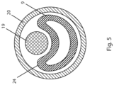
- FIG. 5 shows a cross-sectional view of a sheath 20 containing a catheter body 9 and a wire 19 that has previously been advanced through a side-port of the catheter.
- a wire has been advanced through the side-port of a catheter defining a lumen
- the portion of the catheter lumen distal to the side-port is understood to be "empty" i.e. the wire is absent from that portion of the catheter.
- Fig. 5 illustrates wire 19 pressing against the side of the catheter 8 as the catheter is being withdrawn through sheath 20 whereby the illustrated portion of catheter 8 (i.e. the portion distal of the side-port) is collapsed or deformed.
- this portion of the catheter assists in reducing friction between the wire 19 and catheter 8, thereby ensuring that a position of the wire within the true lumen is substantially maintained.
- wire 19 it is acceptable for wire 19 to be withdrawn a limited distance as catheter 8 is retracted, so long as a distal end of wire 19 remains in the true lumen whereby the wire is operable to function as a bridge or rail for advancing devices thereover.
- the portion of the catheter distal of the side-port is collapsible when a guide-wire is absent from a lumen defined therethrough, i.e. when it is not containing a guide-wire (or another type of wire or wire-shaped device), but retains a non-collapsed or non-deformed configuration when housing a wire or other structure therein.
- the distal tip of the catheter defines a distal end opening or aperture whereby the catheter is operable to be advanced over the guide-wire as an over-the-wire device, or alternatively, a guide-wire may be advanced or withdrawn through the distal end opening of the catheter.
- the wire provides structural (radial) support to the catheter, whereby the distal portion of the catheter housing the wire is operable (has sufficient column strength) to be advanced over the wire and through the anatomy of a patient without ovalization of the catheter, i.e. the catheter retains a non-collapsed configuration.
- the present inventors have conceived and reduced to practice a collapsible tip catheter with a side-port that may be used for re-entry procedures or for advancing into bifurcations.
- the catheter is sufficiently radially collapsible distal of the side port whereby it has a collapsed configuration which allows the catheter to be withdrawn without altering the position of a wire which is extending through the side-port.
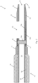
- Fig. 1 illustrates an embodiment of a catheter 8 including a catheter body 9 defining a lumen 23 (a primary catheter lumen), a side-port 13 in fluid communication with lumen 23, a distal portion 22 of catheter body 9, a distal tip 25 defining an end opening 21 which is in fluid communication with lumen 23, and a marker 16.
- Distal portion 22 is the portion of catheter body 9 distal of side-port 13.
- the marker 16 of Fig. 1 includes a marker band 16a and a marker backbone 16b. In the illustrated embodiment, marker band 16a is proximal of side-port 13, and marker backbone 16b is substantially parallel and opposite to side-port 13. Side-port 13 is typically elongated.
- Wire braid layer 14 is covered by proximal sleeve 31.
- the embodiment of Fig. 1 includes side-port 13 located in a recess in the outer surface of the catheter, unlike the embodiment of Fig. 2 (described below) which does not include a recess.
- side-port 13 is capsule-shaped, having a straight elongate portion with a length about 0.1420 ⁇ 0.01 inches (3.61 ⁇ 0.254 mm) and curved end portions, each with a radius of about 0.0200 ⁇ 0.002 inches (0.508 ⁇ 0.051 mm).
- Some embodiments of the catheter have a shaft length of about 47 to 55.2 inches (120 to 140 cm).
- catheter 8 has a shaft length of about 47.24 ⁇ 0.200 inches (about 120 ⁇ 0.5cm).
- the inner diameter of catheter body 9 is about 0.040 ⁇ 0.004 inches (about 1.02 ⁇ 0.102 mm) at the distal end of wire braid layer 14 and is about 0.035 ⁇ 0.004 inches (0.89 ⁇ 0.102 mm) at the distal tip of the catheter (i.e. at or about end opening 21).
- the outer diameter of catheter 8 is about 0.063 ⁇ 0.004 inches (1.6 ⁇ 0.102 mm) at the distal end of wire braid layer 14.
- the distance from the proximal end of marker band 16a to the distal tip of the catheter is about 0.587 ⁇ 0.294 inches (14.91 ⁇ 7.46 mm).
- the distance from the distal end of side-port 13 to the distal tip of the catheter is about 0.332 ⁇ 0.166 inches (8.43 ⁇ 4.21 mm).
- Some embodiments of the catheter may be used with a guide-wire with a 0.035 inch (0.89 mm) outer diameter (OD), in a 6F introducer sheath with an inner diameter of about 0.079 inches (about 2 mm).
- a guide-wire with a 0.035 inch (0.89 mm) outer diameter (OD)
- OD outer diameter
- 6F introducer sheath with an inner diameter of about 0.079 inches (about 2 mm).
- the inner diameter of about 0.035 ⁇ 0.004 inches (0.89 ⁇ 0.102 mm) at end opening 21 will provide a close or tight fit to the guide-wire.
- the relatively larger inner diameter of about 0.040 ⁇ 0.004 inches (about 1.02 ⁇ 0.102 mm) at the distal end of wire braid layer 14 will provide for trackability over the guide-wire as the larger diameter provides for space around wire 19, which reduces friction and binding.
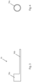
- Fig. 2 a diagrammatic cut away view of a distal portion of the disclosed catheter illustrating materials of an embodiment of the device.
- the example of Fig. 2 comprises a braided shaft 15 including a wire braid layer 14.
- the distal end of braided shaft 15 is proximal of side-port 13.
- wire braid layer 14 is comprised of a metal, for example, stainless steel or Nitinol.
- Alternative embodiments of wire braid layer 14 are comprised of a polymer such as, for example, nylon, Teflon ® , or carbon based thread.
- Wire braid layer 14 is covered by proximal sleeve 31, which in typical embodiments is a polymer, such as, for example, Pebax ® (a thermoplastic elastomer) or another type of nylon.
- a Pebax layer 11 extends distally of braided shaft 15 and ends proximal of side-port 13.
- the distal end of Pebax layer 11 abuts Grilamid ® layer 12 (a plastic comprising a polyamide), which extends distally to Grilamid distal end 12a.
- Grilamid distal end 12a is between the proximal and distal ends of side-port 13 such that there is a transition in the material comprising catheter body 9 from Grilamid layer 12 to nylon layer 18 at the side-port.
- Pebax layer 11 is replaced by another polymer, for example, another type of nylon.
- Grilamid layer 12 is replaced by another polymer, for example, Pebax or another type of nylon.
- Fig. 2 also illustrates a polytetrafluoroethylene (PTFE) liner extending substantially the entire length of lumen 23 (a primary catheter lumen) to facilitate travel over a guide-wire.
- PTFE liner 10 has a substantially constant thickness of about 0.0013 ⁇ 0.0005 inches (0.0330 ⁇ 0.0127 mm), and in comparison to nylon layer 18 and Grilamid layer 12, is relatively flexible (it has modulus of elasticity typically ranging from about 0.39 to 0.6 gigapascals (GPa)), whereby it does not have a substantially significant effect on the rigidity of catheter 8.
- GPa gigapascals
- Examples of the catheter which are not part of the invention are operable to passively collapse or deform distal of the side-port 13, as described above, as well as being operable to be advanced over a wire without compromising integrity and without experiencing ovalization. Avoidance of ovalization is achieved, for example, by distal portion 22 being configured to be sufficiently axially stiff (i.e. having sufficient column strength) to be advanceable (for example, over a guide-wire) while still being sufficiently radially flexible to be passively collapsible.
- the distal portion of the catheter (distal of the side-port) comprises a layer of material (nylon layer 18) that is stiff enough to provide adequate column strength and, in the disclosed embodiments, is thin enough to provide collapsibility.
- nylon layer 18 which forms a significant part of distal portion 22, is typically a VESTAMID ® nylon having stiffness (a modulus of elasticity) of about 1.4 ⁇ 0.14 GPa.
- Nylon layer 18 tapers distally in thickness from about 0.0055 ⁇ 0.0006 inches (0.1397 ⁇ 0.014 mm) to about 0.002 ⁇ 0.0002 inches (0.0508 ⁇ 0.005 mm) and in outer diameter from about 0.049 ⁇ 0.005 inches (1.2446 ⁇ 0.124 mm) to about 0.042 ⁇ 0.004 inches (1.0668 ⁇ 0.107 mm).
- nylon layer 18 forms an outer layer of distal portion 22, an outer diameter of nylon layer 18 is also an outer diameter of catheter 8. As previously described, in typical embodiments, nylon layer 18 is sufficiently stiff such that distal portion 22 of catheter 8 is advancable over a wire without experiencing ovalization, i.e. while retaining a substantially non-collapsed or non-deformed configuration.
- distal portion 22 In use, when a catheter 8, for example as described hereinabove, is withdrawn or retracted within a sheath after a wire is extended through side-port 13, distal portion 22 will collapse, i.e. will adopt a collapsed or deformed configuration, when force is applied against an outer surface thereof, for example when the wire pushes against it, whereby, in a manner previously described, the catheter can be withdrawn or retracted without substantially retracted the wire 19 positioned therethrough.
- distal portion 22 is also sufficiently resilient to return to a non-collapsed or non-deformed configuration when the wire is retracted into the catheter lumen, i.e. when the force applied by the wire to the outer surface of distal portion 22 is removed.
- Fig. 2 further includes a marker 16 comprising radiopaque marker band 16a and marker backbone 16b which may be used to visualize the location of side-port 13 under imaging.
- Marker 16 is typically comprised of a radiopaque metal, for example, stainless steel, platinum, or a mixture of platinum and iridium.
- a proximal portion of marker 16, marker band 16a is proximal of side-port 13 such that marker band 16a may be used for longitudinal positioning of side-port 13.
- Marker backbone 16b is substantially opposite to side-port 13, i.e. aligned at about 180° relative to the side-port, such that marker backbone 16b is operable to facilitate rotational positioning of side-port 13.
- Marker backbone 16b may also be used for longitudinal positioning.
- FIG. 2 there is a transition in material at or about a location of the side-port 13.
- Marker backbone 16b extends from marker band 16a (which is proximal of side-port 13) to a location distal of the side-port 13 thereby providing support to catheter body 9 to compensate, at least in part, for structural weaknesses caused by the side-port and transition of material at that location.
- Grilamid ® layer 12 is stiffer than both Pebax ® layer 11 and nylon layer 18, thereby providing further support to catheter body 9 proximally of the side-port 13, as well as to a portion of the catheter body located at a proximal portion of the side-port 13 itself i.e.
- Grilamid layer 12 functions as a support layer.
- Marker backbone 16b is positioned or embedded in catheter body 9 substantially opposite side-port 13 and, in some embodiments, extends somewhat distally beyond the side-port 13 while avoiding interfering with (i.e. reducing) the collapsibility of distal portion 22 of catheter body 9.
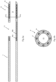
- Fig. 3 is an enlarged side cutaway view of marker 16.
- the length of marker 16 is about 0.256 ⁇ 0.026 inches (6.50 ⁇ 0.066 mm)
- the length of marker backbone 16b is about 0.216 ⁇ 0.022 inches (5.48 ⁇ 0.559 mm)
- the thickness of marker backbone 16b is about 0.010 ⁇ 0.001 inches (0.25 ⁇ 0.03 mm)
- the length of marker band 16a is about 0.040 ⁇ 0.004 inches (about 1.02 ⁇ 0.102 mm)
- the outer diameter of marker band 16a is about 0.050 ⁇ 0.005 inches (1.27 ⁇ 0.13 mm).
- the length of the length of marker backbone 16b is about 0.235 ⁇ 0.022 inches (5.07 ⁇ 0.559 mm).
- Fig. 4 shows an end cutaway or cross-sectional view of the marker of Fig. 3 through marker band 16a, which has an outer diameter of about 0.050 ⁇ 0.005 inches (1.27 ⁇ 0.13 mm) and an inner diameter of about 0.044 ⁇ 0.004 inches (1.12 ⁇ 0.11 mm).
- marker band 16a has an outer diameter of about 0.052 ⁇ 0.005 inches (1.32 ⁇ 0.13 mm) and an inner diameter of about 0.046 ⁇ 0.004 inches (1.17 ⁇ 0.11 mm).
- Fig. 5 illustrates a cross-sectional view of a sheath 20 containing a catheter body 9 and a wire 19 extending through a side-port (not shown) of the catheter.
- Typical embodiments of a catheter body 9 have a substantially circular cross sectional shape, and a substantially constant wall thickness, when the catheter is not bent or distorted. Some alternative embodiments have a non-circular cross sectional shape.
- Fig. 6a is a side cutaway view of an alternative embodiment of catheter body 9 having elongate support members 27 in distal portion 22.
- Such embodiments of the catheter comprise at least two elongate support members 27 for providing longitudinal support while allowing the distal portion to still be collapsible or inwardly deformable.
- elongate support members 27 are comprised of a metal, but alternative embodiments could be comprised of other materials having the appropriate support strength.
- Fig. 6b is a cross-sectional view of the embodiment of Fig. 6a at cut-away line bb illustrating the elongate support members 27 arranged in a substantially circular configuration surrounding the primary catheter lumen, lumen 23.
- polymer 28 is comprised of a biocompatible stretchable polymer, for example, silicone elastomers or polydimethylsiloxane (PDMS).
- PDMS polydimethylsiloxane
- the polymer can be thinner and more deformable relative to an embodiment without elongate support members 27 since the elongate support members are providing column strength.
- Some embodiments further comprise a radiopaque material which coats elongate support members 27.
- distal portion 22 of catheter body 9 is operable to collapse inwardly into the primary catheter lumen (lumen 23) and thereby temporarily adopt a reduced profile in a collapsed configuration when a controlled force is applied to the distal portion of the catheter body.
- Fig. 7 is a side cutaway view of such an embodiment, wherein catheter body 9 has a shape memory element 29.
- Shape memory element 29 can comprise any appropriate structure, for example, a stent or a coil, wherein the shape memory element is configured to produce said controlled force when heated.
- Wire 30 connects shape memory element 29 to a source of heat.
- Some embodiments further comprise a radiopaque material coating the shape memory element.
- polymer 28 of the distal portion comprises a biocompatible stretchable polymer.
- catheter 8 having a shape memory element 29 include a distal portion 22 which comprises a shape memory element 29, wherein the shape memory element is configured to expand and produce an expanding force in distal portion 22 when heated, whereby the distal portion expands (i.e. adapts an expanded configuration) to thereby allow advancement of the distal portion over a guide-wire.
- distal portion 22 of catheter body 9 is operable to collapse inwardly into the primary catheter lumen when shape memory element 29 not heated, thereby adopting a reduced profile in a collapsed configuration.
- Embodiments of the present invention may be used, for example, when withdrawing or retracting a re-entry catheter (either through a lumen or through tissue) having a wire positioned through a side-port of the catheter (into a true vessel lumen) or when withdrawing a bifurcation catheter having a wire positioned through a side-port of the catheter (into a branch artery or vein).
- One embodiment of the invention is for a method of using the catheter of Figs. 1 or 2 , wherein distal portion 22 has an outer diameter which tapers from about 0.049 ⁇ 0.005 inches (1.2446 ⁇ 0.124 mm) to about 0.042 ⁇ 0.004 inches (1.0668 ⁇ 0.107 mm), and the catheter is used with a guide-wire with a 0.035 inch (0.89 mm) outer diameter and a 6F introducer sheath (with an inner diameter of about 0.079 inches or about 2 mm), wherein the method comprises withdrawing the catheter from the sheath with the guide-wire extending through the side-port.
- Example 1 A catheter comprising a catheter body, the catheter body defining at least a primary catheter lumen and at least one side-port in communication with the primary catheter lumen, and a distal portion of the catheter extending distal to the at least one side-port, the side-port being configured to allow travel of a device (a wire or other component) therethrough, wherein the distal portion of the catheter is radially collapsible.
- a device a wire or other component
- Example 2 The catheter of example 1, wherein the distal portion of the catheter body is operable to collapse inwardly into the primary catheter lumen and thereby temporarily adopt a reduced profile in a collapsed configuration when force is applied to an outer surface of the distal portion of the catheter body.
Landscapes
- Health & Medical Sciences (AREA)
- Life Sciences & Earth Sciences (AREA)
- Animal Behavior & Ethology (AREA)
- Veterinary Medicine (AREA)
- Public Health (AREA)
- General Health & Medical Sciences (AREA)
- Engineering & Computer Science (AREA)
- Biomedical Technology (AREA)
- Heart & Thoracic Surgery (AREA)
- Hematology (AREA)
- Anesthesiology (AREA)
- Pulmonology (AREA)
- Biophysics (AREA)
- Epidemiology (AREA)
- Vascular Medicine (AREA)
- Surgery (AREA)
- Chemical & Material Sciences (AREA)
- Chemical Kinetics & Catalysis (AREA)
- Nuclear Medicine, Radiotherapy & Molecular Imaging (AREA)
- Cardiology (AREA)
- Oral & Maxillofacial Surgery (AREA)
- Transplantation (AREA)
- Molecular Biology (AREA)
- Medical Informatics (AREA)
- Media Introduction/Drainage Providing Device (AREA)
- Medicinal Chemistry (AREA)
- Polymers & Plastics (AREA)
- Organic Chemistry (AREA)
Claims (14)
- Katheter (8) zur Verwendung mit einem Draht (19) oder einer anderen Komponente, umfassend einen Katheterkörper (9), wobei der Katheterkörper (9) mindestens ein primäres Katheterlumen (23) und mindestens eine Seitenöffnung (13) in Verbindung mit dem primären Katheterlumen (23) definiert, wobei sich ein distaler Teil (22) des Katheterkörpers (9) distal von der mindestens einen Seitenöffnung (13) erstreckt, dadurch gekennzeichnet
dass die Seitenöffnung (13) eingerichtet ist, das Hindurchführen eines Drahtes (19) oder einer anderen Komponente durch sie hindurch zu ermöglichen, wobei der distale Teil (22) des Katheterkörpers (9) betätigbar ist, um nach innen in das primäre Katheterlumen (23) zu kollabieren und dadurch in einer kollabierten Konfiguration vorübergehend ein reduziertes Profil anzunehmen, wenn eine Kraft auf eine Außenfläche des distalen Teils (22) des Katheterkörpers (9) ausgeübt wird, die kollabierte Konfiguration es ermöglicht, den Katheter zurückzuziehen, ohne die Position des Drahtes (19) oder einer anderen Komponente, der/die sich durch die Seitenöffnung (13) erstreckt, zu verändern. - Katheter (8) nach Anspruch 1, wobei der distale Teil (22) des Katheters eine Materialschicht umfasst, die betätigbar ist, um über einen Führungsdraht (19) im Wesentlichen ohne Verformung des distalen Teils (22) des Katheterkörpers (9) vorgeschoben werden zu können, und die ferner betätigbar ist, um bei Anwendung der Kraft radial zu kollabieren.
- Katheter (8) nach Anspruch 2, wobei die Materialschicht eine flexible Nylonschicht mit einer Steifigkeit von etwa 1,4 ± 0,14 GPa umfasst.
- Katheter (8) nach Anspruch 3, wobei der Katheterkörper (9) eine Stützschicht mit einem proximalen Ende proximal der Seitenöffnung (13) und einem distalen Ende an der Seitenöffnung (13) aufweist, wobei die Stützschicht ein Kunststoff ist, der steifer ist als die flexible Nylonschicht.
- Katheter (8) nach Anspruch 4, wobei der Kunststoff ein Polyamid ist.
- Katheter (8) nach Anspruch 1, wobei die Seitenöffnung (13) in einer Aussparung in einer Außenfläche des Katheters (8) angeordnet ist.
- Katheter (8) nach Anspruch 1, ferner umfassend eine Visualisierungsmarkierung mit einem Markierungsrückgrat (16b), das im Wesentlichen parallel und gegenüber der Seitenöffnung (13) angeordnet ist, wobei das Markierungsrückgrat (16b) zur Erleichterung der Drehpositionierung des Katheters (8) betätigt werden kann und das Markierungsrückgrat (16b) dem Katheterkörper (9) stützt.
- Katheter (8) nach Anspruch 7, wobei das Markierungsrückgrat (16b) aus einem Metall besteht.
- Katheter (8) nach Anspruch 8, wobei sich das Markierungsrückgrat (16b) von proximal der Seitenöffnung (13) zu einer Stelle distal der Seitenöffnung (13) erstreckt, wodurch der Katheterkörper (9) an einer Stelle der Seitenöffnung (13) gestützt wird.
- Katheter (8) nach Anspruch 1, wobei die Kraft eine gesteuerte Kraft umfasst und wobei der distale Teil (22) des Katheterkörpers (9) betätigbar ist, um nach innen in das primäre Katheterlumen (23) zu kollabieren und dadurch vorübergehend ein reduziertes Profil in einer kollabierten Konfiguration anzunehmen, wenn die gesteuerte Kraft auf den distalen Teil (22) des Katheterkörpers (9) ausgeübt wird, und der distale Teil (22) ein Formgedächtniselement (29) umfasst, das eingerichtet ist, die gesteuerte Kraft zu erzeugen, wenn es erhitzt wird.
- Katheter (8) nach Anspruch 1, wobei der distale Teil (22) ein Formgedächtniselement (29) umfasst, wobei das Formgedächtniselement (29) eingerichtet ist, sich auszudehnen und eine Ausdehnungskraft in dem distalen Teil (22) erzeugt, wenn es erhitzt wird, wodurch der distale Teil (22) eine ausgedehnte Konfiguration annimmt, und wobei der distale Teil (22) des Katheterkörpers (9) betätigbar ist, um nach innen in das primäre Katheterlumen (23) zu kollabieren, wenn das Formgedächtniselement (29) nicht erhitzt wird, wodurch der distale Teil (22) eine kollabierte Konfiguration annimmt.
- Katheter (8) nach Anspruch 10 oder 11, wobei das Formgedächtniselement (29) einen Stent umfasst.
- Katheter (8) nach Anspruch 10 oder 11, ferner umfassend ein röntgendichtes Material, das das Formgedächtniselement (29) beschichtet.
- Katheter (8) nach Anspruch 10 oder 11, wobei der distale Teil (22) ein dehnbares Polymer umfasst.
Applications Claiming Priority (3)
| Application Number | Priority Date | Filing Date | Title |
|---|---|---|---|
| US201461929158P | 2014-01-20 | 2014-01-20 | |
| US201461932891P | 2014-01-29 | 2014-01-29 | |
| PCT/IB2015/050396 WO2015107506A2 (en) | 2014-01-20 | 2015-01-19 | Collapsible tip re-entry catheter |
Publications (3)
| Publication Number | Publication Date |
|---|---|
| EP3096830A2 EP3096830A2 (de) | 2016-11-30 |
| EP3096830A4 EP3096830A4 (de) | 2018-02-14 |
| EP3096830B1 true EP3096830B1 (de) | 2025-06-04 |
Family
ID=53543572
Family Applications (1)
| Application Number | Title | Priority Date | Filing Date |
|---|---|---|---|
| EP15737506.4A Active EP3096830B1 (de) | 2014-01-20 | 2015-01-19 | Wiedereintrittskatheter mit zusammenklappbarer spitze |
Country Status (3)
| Country | Link |
|---|---|
| US (1) | US10857329B2 (de) |
| EP (1) | EP3096830B1 (de) |
| WO (1) | WO2015107506A2 (de) |
Families Citing this family (32)
| Publication number | Priority date | Publication date | Assignee | Title |
|---|---|---|---|---|
| ES2975734T3 (es) | 2015-01-29 | 2024-07-12 | Becton Dickinson Co | Catéter integrado de inserción rápida |
| MX2018005116A (es) | 2015-10-26 | 2018-09-05 | Neuwave Medical Inc | Sistemas de suministro de energia y sus usos. |
| EP4736931A2 (de) | 2019-04-05 | 2026-05-06 | Traverse Vascular, Inc. | Wiedereintrittskatheter zur durchquerung chronischer totalverschlüsse |
| US12402946B2 (en) | 2019-06-19 | 2025-09-02 | Boston Scientific Scimed, Inc. | Breakdown of laser pulse energy for breakup of vascular calcium |
| US20200406010A1 (en) | 2019-06-26 | 2020-12-31 | Boston Scientific Scimed, Inc. | Side light direction plasma system to disrupt vascular lesions |
| MX2022002691A (es) | 2019-09-10 | 2022-04-07 | Bard Access Systems Inc | Cateter central insertado rapidamente y metodos del mismo. |
| JP7586900B2 (ja) | 2019-09-24 | 2024-11-19 | バード・アクセス・システムズ,インコーポレーテッド | 患者の血管系にアクセスするためのカテーテルアセンブリ |
| JP7729814B2 (ja) | 2019-10-22 | 2025-08-26 | バード・アクセス・システムズ,インコーポレーテッド | 迅速挿入型中心静脈カテーテル |
| WO2021081434A1 (en) | 2019-10-25 | 2021-04-29 | Bard Access Systems, Inc. | Guidewire-management devices and methods thereof |
| US12274497B2 (en) | 2019-12-18 | 2025-04-15 | Bolt Medical, Inc. | Multiplexer for laser-driven intravascular lithotripsy device |
| JP7611924B2 (ja) | 2020-01-23 | 2025-01-10 | バード・アクセス・システムズ,インコーポレーテッド | 迅速挿入型中心静脈カテーテルシステム |
| US12446961B2 (en) | 2020-02-10 | 2025-10-21 | Bolt Medical, Inc. | System and method for pressure monitoring within a catheter system |
| MX2022011216A (es) | 2020-03-13 | 2022-10-07 | Bard Access Systems Inc | Dispositivos y metodos de manejo de alambres de guia. |
| MX2022011209A (es) | 2020-03-13 | 2022-10-07 | Bard Access Systems Inc | Dispositivos y metodos de manejo de alambres de guia. |
| US12611253B2 (en) | 2020-03-18 | 2026-04-28 | Boston Scientific Scimed, Inc. | Optical analyzer assembly and method for intravascular lithotripsy device |
| JP7788397B2 (ja) | 2020-04-23 | 2025-12-18 | バード・アクセス・システムズ,インコーポレーテッド | カテーテルアセンブリを備えた迅速挿入型中心静脈カテーテル |
| US20210353359A1 (en) | 2020-05-12 | 2021-11-18 | Bolt Medical, Inc. | Active alignment system and method for optimizing optical coupling of multiplexer for laser-driven intravascular lithotripsy device |
| CA3181532A1 (en) | 2020-05-21 | 2021-11-25 | Bard Access Systems, Inc. | Rapidly insertable central catheters including catheter assemblies |
| US12295654B2 (en) | 2020-06-03 | 2025-05-13 | Boston Scientific Scimed, Inc. | System and method for maintaining balloon integrity within intravascular lithotripsy device with plasma generator |
| CN114099898B (zh) | 2020-06-29 | 2026-03-17 | 巴德阿克塞斯系统股份有限公司 | 包括导管组件的可快速插入的中心导管及其方法 |
| MX2023000019A (es) | 2020-06-29 | 2023-04-11 | Bard Access Systems Inc | Catéteres centrales que se insertan rápidamente incluyendo ensamblajes y métodos de los mismos. |
| EP4185362A1 (de) | 2020-07-31 | 2023-05-31 | Bard Access Systems, Inc. | Zweiteiliger schnell einsetzbarer zentraler katheter, einführvorrichtungen dafür und verfahren dafür |
| BR112023001383A2 (pt) | 2020-08-03 | 2023-02-14 | Bard Access Systems Inc | Dispositivo de colocação de cateter de dilatador e agulha divisíveis e métodos associados |
| CN217041031U (zh) | 2020-10-28 | 2022-07-26 | 巴德阿克塞斯系统股份有限公司 | 导管放置系统 |
| AU2021393463B2 (en) | 2020-12-03 | 2025-11-27 | Bard Access Systems, Inc. | Needle tip blunting using a length of a guidewire |
| CA3203290A1 (en) | 2020-12-17 | 2022-06-23 | Bard Access Systems, Inc. | Rapidly insertable central catheters and assemblies |
| CA3203787A1 (en) | 2020-12-21 | 2022-06-30 | Bard Access Systems, Inc. | Fluid path optimization in catheter insertion systems |
| WO2022140429A1 (en) | 2020-12-21 | 2022-06-30 | Bard Access Systems, Inc. | Optimized structural support in catheter insertion systems |
| WO2022154954A1 (en) | 2021-01-12 | 2022-07-21 | Bolt Medical, Inc. | Balloon assembly for valvuloplasty catheter system |
| US12533184B2 (en) | 2022-04-02 | 2026-01-27 | Boston Scientific Scimed, Inc. | Optical connector assembly for intravascular lithotripsy device |
| WO2024025799A1 (en) * | 2022-07-28 | 2024-02-01 | University Of Maine System Board Of Trustees | Methods of altering protein deposition on urinary catheters and devices |
| US12599748B2 (en) | 2022-12-06 | 2026-04-14 | Bard Access Systems, Inc. | Catheter tips for rapidly insertable central catheters and methods thereof |
Family Cites Families (44)
| Publication number | Priority date | Publication date | Assignee | Title |
|---|---|---|---|---|
| US2116083A (en) | 1935-05-11 | 1938-05-03 | Rusch Willy | Rubber tube for medical use |
| US4774949A (en) | 1983-06-14 | 1988-10-04 | Fogarty Thomas J | Deflector guiding catheter |
| US4531943A (en) | 1983-08-08 | 1985-07-30 | Angiomedics Corporation | Catheter with soft deformable tip |
| US4552554A (en) * | 1984-06-25 | 1985-11-12 | Medi-Tech Incorporated | Introducing catheter |
| JP3137646B2 (ja) * | 1991-04-05 | 2001-02-26 | ボストン サイエンティフィック コーポレイション | 硬度調節可能な可変カテーテル器具 |
| US6821287B1 (en) * | 1991-05-24 | 2004-11-23 | Advanced Cardiovascular Systems, Inc. | Multi-mode vascular catheter system |
| US5447503A (en) * | 1991-08-14 | 1995-09-05 | Cordis Corporation | Guiding catheter tip having a tapered tip with an expandable lumen |
| US5205830A (en) * | 1991-11-12 | 1993-04-27 | Arrow International Investment Corporation | Catheter assembly |
| US6090072A (en) * | 1992-10-15 | 2000-07-18 | Scimed Life Systems, Inc. | Expandable introducer sheath |
| US5531685A (en) * | 1993-06-11 | 1996-07-02 | Catheter Research, Inc. | Steerable variable stiffness device |
| US5637091A (en) * | 1995-08-31 | 1997-06-10 | Hakky; Said I. | Collapsible catheter |
| US5788680A (en) * | 1996-07-09 | 1998-08-04 | Linder; Gerald Seymour | Dual-lumen suction catheter with multiple apertures in the vent lumen |
| US6312374B1 (en) * | 1997-03-06 | 2001-11-06 | Progenix, Llc | Radioactive wire placement catheter |
| US6217527B1 (en) * | 1998-09-30 | 2001-04-17 | Lumend, Inc. | Methods and apparatus for crossing vascular occlusions |
| US6179827B1 (en) * | 1998-03-16 | 2001-01-30 | Chase Medical | Catheter having integral expandable/collapsible lumen |
| US6358238B1 (en) * | 1999-09-02 | 2002-03-19 | Scimed Life Systems, Inc. | Expandable micro-catheter |
| US7004173B2 (en) | 2000-12-05 | 2006-02-28 | Lumend, Inc. | Catheter system for vascular re-entry from a sub-intimal space |
| US6872433B2 (en) * | 2001-03-27 | 2005-03-29 | The Regents Of The University Of California | Shape memory alloy/shape memory polymer tools |
| US20030032936A1 (en) | 2001-08-10 | 2003-02-13 | Lederman Robert J. | Side-exit catheter and method for its use |
| US6866655B2 (en) * | 2002-04-23 | 2005-03-15 | Scimed Life Systems, Inc. | Medical device with atraumatic tip |
| US7717934B2 (en) * | 2002-06-14 | 2010-05-18 | Ev3 Inc. | Rapid exchange catheters usable with embolic protection devices |
| US7037293B2 (en) * | 2002-11-15 | 2006-05-02 | Boston Scientific Scimed, Inc. | Rapid exchange catheter with depressable channel |
| US20040260271A1 (en) * | 2003-06-18 | 2004-12-23 | Huyser Richard F. | Extended fenestration catheter with internal coil and method of making the same |
| US7087053B2 (en) | 2004-05-27 | 2006-08-08 | St. Jude Medical, Atrial Fibrillation Division, Inc. | Catheter with bifurcated, collapsible tip for sensing and ablating |
| CN101001659A (zh) | 2004-08-11 | 2007-07-18 | 株式会社钟化 | 导管 |
| CA2590275C (en) * | 2004-12-07 | 2010-03-09 | Wilson-Cook Medical Inc. | Catheter aperture with related structures and method |
| US20070208302A1 (en) * | 2006-01-26 | 2007-09-06 | Webster Mark W | Deflection control catheters, support catheters and methods of use |
| EP1825872A3 (de) | 2006-02-23 | 2007-10-03 | Levitronix LLC | Drainagekanüle, Perfusionskanüle sowie Blut-Managementsystem |
| US7815601B2 (en) * | 2007-02-05 | 2010-10-19 | Boston Scientific Scimed, Inc. | Rapid exchange enteral stent delivery system |
| US8226619B2 (en) | 2007-06-15 | 2012-07-24 | Kyphon Sarl | Systems and methods for needle access to an intervertebral disc |
| US8285362B2 (en) | 2007-06-28 | 2012-10-09 | W. L. Gore & Associates, Inc. | Catheter with deflectable imaging device |
| US8292872B2 (en) * | 2007-06-29 | 2012-10-23 | Cook Medical Technologies Llc | Distal wire stop having adjustable handle |
| JP5452498B2 (ja) * | 2007-11-01 | 2014-03-26 | シー・アール・バード・インコーポレーテッド | 三重管腔端を含むカテーテル組立体 |
| US20090209941A1 (en) | 2008-02-19 | 2009-08-20 | William Cook Europe, Aps | Implant deployment catheter |
| US7947012B2 (en) * | 2008-04-24 | 2011-05-24 | Medtronic Vascular, Inc. | Aspiration catheter having selectively deformable tip |
| US8562559B2 (en) | 2008-05-14 | 2013-10-22 | Onset Medical Corporation | Expandable iliac sheath and method of use |
| US8057430B2 (en) * | 2009-02-20 | 2011-11-15 | Boston Scientific Scimed, Inc. | Catheter with skived tubular member |
| CH700478A1 (de) * | 2009-02-27 | 2010-08-31 | Schwager Medica | Katheter. |
| AU2011279479B2 (en) | 2010-07-15 | 2015-09-17 | Becton, Dickinson And Company | A catheter hole having an inclined trailing edge |
| US9089350B2 (en) * | 2010-11-16 | 2015-07-28 | Boston Scientific Scimed, Inc. | Renal denervation catheter with RF electrode and integral contrast dye injection arrangement |
| US8956376B2 (en) * | 2011-06-30 | 2015-02-17 | The Spectranetics Corporation | Reentry catheter and method thereof |
| US20130085477A1 (en) | 2011-09-29 | 2013-04-04 | Tyco Healthcare Group Lp | Catheter with tapering surfaces |
| WO2013095986A1 (en) * | 2011-12-20 | 2013-06-27 | Cook Medical Technologies Llc | Biliary system catheter |
| US20130197353A1 (en) * | 2012-01-27 | 2013-08-01 | Randolf Von Oepen | Radiopaque marker for a catheter |
-
2015
- 2015-01-19 EP EP15737506.4A patent/EP3096830B1/de active Active
- 2015-01-19 WO PCT/IB2015/050396 patent/WO2015107506A2/en not_active Ceased
-
2016
- 2016-07-19 US US15/214,084 patent/US10857329B2/en active Active
Also Published As
| Publication number | Publication date |
|---|---|
| US20160325073A1 (en) | 2016-11-10 |
| US10857329B2 (en) | 2020-12-08 |
| WO2015107506A3 (en) | 2015-11-19 |
| EP3096830A2 (de) | 2016-11-30 |
| EP3096830A4 (de) | 2018-02-14 |
| WO2015107506A2 (en) | 2015-07-23 |
Similar Documents
| Publication | Publication Date | Title |
|---|---|---|
| EP3096830B1 (de) | Wiedereintrittskatheter mit zusammenklappbarer spitze | |
| CN115023258B (zh) | 用于脉管导管的引导设备 | |
| JP7643673B2 (ja) | ハイブリッド経中隔拡張器 | |
| JP6639545B2 (ja) | 進入及び追跡用迅速交換拡張器を持つ頸動脈シース並びに使用方法 | |
| US11712544B2 (en) | Guide extension catheter | |
| US11617600B2 (en) | Apparatus for forming a passageway in tissue and associated interventional medical systems | |
| EP2994187B1 (de) | Zugangsvorrichtung für transseptale behandlungen | |
| EP2692391B1 (de) | Katheter zur Behandlung von Körperdurchgängen | |
| EP3169256B1 (de) | Eus-geführte zugriffsvorrichtung | |
| US20170333681A1 (en) | Devices for Assisting with Advancement of Catheters and Related Systems and Methods | |
| US20140031843A1 (en) | Hypotube based support catheter | |
| US20160100859A1 (en) | Fossa ovalis penetration | |
| US10828471B2 (en) | Balloon catheter having a retractable sheath | |
| US10864354B2 (en) | Hydraulic auto crossing balloon/catheter | |
| US20200230376A1 (en) | Balloon catheter with adjustable sheath | |
| US11129964B2 (en) | Trapping sheaths and guide catheters | |
| JP6633513B2 (ja) | カテーテル及びカテーテルセット | |
| US20180008362A1 (en) | Secure Insertion Of An Insertion Device | |
| CN119173293A (zh) | 用于生物组织穿刺扩张的设备 | |
| JP2016174828A (ja) | 医療器具 |
Legal Events
| Date | Code | Title | Description |
|---|---|---|---|
| PUAI | Public reference made under article 153(3) epc to a published international application that has entered the european phase |
Free format text: ORIGINAL CODE: 0009012 |
|
| 17P | Request for examination filed |
Effective date: 20160816 |
|
| AK | Designated contracting states |
Kind code of ref document: A2 Designated state(s): AL AT BE BG CH CY CZ DE DK EE ES FI FR GB GR HR HU IE IS IT LI LT LU LV MC MK MT NL NO PL PT RO RS SE SI SK SM TR |
|
| AX | Request for extension of the european patent |
Extension state: BA ME |
|
| DAX | Request for extension of the european patent (deleted) | ||
| RIC1 | Information provided on ipc code assigned before grant |
Ipc: A61M 25/00 20060101AFI20170822BHEP Ipc: A61L 29/14 20060101ALI20170822BHEP Ipc: A61L 29/06 20060101ALI20170822BHEP Ipc: A61B 17/3207 20060101ALI20170822BHEP Ipc: A61M 25/16 20060101ALI20170822BHEP Ipc: A61F 2/844 20130101ALI20170822BHEP Ipc: A61B 17/32 20060101ALI20170822BHEP Ipc: A61M 25/01 20060101ALI20170822BHEP |
|
| A4 | Supplementary search report drawn up and despatched |
Effective date: 20180115 |
|
| RIC1 | Information provided on ipc code assigned before grant |
Ipc: A61M 25/00 20060101AFI20180109BHEP Ipc: A61L 29/06 20060101ALI20180109BHEP Ipc: A61B 17/32 20060101ALI20180109BHEP Ipc: A61M 25/16 20060101ALI20180109BHEP Ipc: A61F 2/844 20130101ALI20180109BHEP Ipc: A61L 29/14 20060101ALI20180109BHEP Ipc: A61B 17/3207 20060101ALI20180109BHEP Ipc: A61M 25/01 20060101ALI20180109BHEP |
|
| RAP3 | Party data changed (applicant data changed or rights of an application transferred) |
Owner name: BAYLIS MEDICAL COMPANY INC. |
|
| STAA | Information on the status of an ep patent application or granted ep patent |
Free format text: STATUS: EXAMINATION IS IN PROGRESS |
|
| RAP1 | Party data changed (applicant data changed or rights of an application transferred) |
Owner name: BOSTON SCIENTIFIC MEDICAL DEVICE LIMITED |
|
| 17Q | First examination report despatched |
Effective date: 20220915 |
|
| GRAP | Despatch of communication of intention to grant a patent |
Free format text: ORIGINAL CODE: EPIDOSNIGR1 |
|
| STAA | Information on the status of an ep patent application or granted ep patent |
Free format text: STATUS: GRANT OF PATENT IS INTENDED |
|
| INTG | Intention to grant announced |
Effective date: 20250102 |
|
| GRAS | Grant fee paid |
Free format text: ORIGINAL CODE: EPIDOSNIGR3 |
|
| GRAA | (expected) grant |
Free format text: ORIGINAL CODE: 0009210 |
|
| STAA | Information on the status of an ep patent application or granted ep patent |
Free format text: STATUS: THE PATENT HAS BEEN GRANTED |
|
| AK | Designated contracting states |
Kind code of ref document: B1 Designated state(s): AL AT BE BG CH CY CZ DE DK EE ES FI FR GB GR HR HU IE IS IT LI LT LU LV MC MK MT NL NO PL PT RO RS SE SI SK SM TR |
|
| REG | Reference to a national code |
Ref country code: GB Ref legal event code: FG4D |
|
| REG | Reference to a national code |
Ref country code: CH Ref legal event code: EP |
|
| REG | Reference to a national code |
Ref country code: DE Ref legal event code: R096 Ref document number: 602015091768 Country of ref document: DE |
|
| REG | Reference to a national code |
Ref country code: IE Ref legal event code: FG4D |
|
| REG | Reference to a national code |
Ref country code: NL Ref legal event code: MP Effective date: 20250604 |
|
| PG25 | Lapsed in a contracting state [announced via postgrant information from national office to epo] |
Ref country code: FI Free format text: LAPSE BECAUSE OF FAILURE TO SUBMIT A TRANSLATION OF THE DESCRIPTION OR TO PAY THE FEE WITHIN THE PRESCRIBED TIME-LIMIT Effective date: 20250604 Ref country code: ES Free format text: LAPSE BECAUSE OF FAILURE TO SUBMIT A TRANSLATION OF THE DESCRIPTION OR TO PAY THE FEE WITHIN THE PRESCRIBED TIME-LIMIT Effective date: 20250604 |
|
| REG | Reference to a national code |
Ref country code: LT Ref legal event code: MG9D |
|
| PG25 | Lapsed in a contracting state [announced via postgrant information from national office to epo] |
Ref country code: NO Free format text: LAPSE BECAUSE OF FAILURE TO SUBMIT A TRANSLATION OF THE DESCRIPTION OR TO PAY THE FEE WITHIN THE PRESCRIBED TIME-LIMIT Effective date: 20250904 Ref country code: GR Free format text: LAPSE BECAUSE OF FAILURE TO SUBMIT A TRANSLATION OF THE DESCRIPTION OR TO PAY THE FEE WITHIN THE PRESCRIBED TIME-LIMIT Effective date: 20250905 |
|
| PG25 | Lapsed in a contracting state [announced via postgrant information from national office to epo] |
Ref country code: PL Free format text: LAPSE BECAUSE OF FAILURE TO SUBMIT A TRANSLATION OF THE DESCRIPTION OR TO PAY THE FEE WITHIN THE PRESCRIBED TIME-LIMIT Effective date: 20250604 |
|
| PG25 | Lapsed in a contracting state [announced via postgrant information from national office to epo] |
Ref country code: BG Free format text: LAPSE BECAUSE OF FAILURE TO SUBMIT A TRANSLATION OF THE DESCRIPTION OR TO PAY THE FEE WITHIN THE PRESCRIBED TIME-LIMIT Effective date: 20250604 |
|
| PG25 | Lapsed in a contracting state [announced via postgrant information from national office to epo] |
Ref country code: HR Free format text: LAPSE BECAUSE OF FAILURE TO SUBMIT A TRANSLATION OF THE DESCRIPTION OR TO PAY THE FEE WITHIN THE PRESCRIBED TIME-LIMIT Effective date: 20250604 |
|
| PG25 | Lapsed in a contracting state [announced via postgrant information from national office to epo] |
Ref country code: RS Free format text: LAPSE BECAUSE OF FAILURE TO SUBMIT A TRANSLATION OF THE DESCRIPTION OR TO PAY THE FEE WITHIN THE PRESCRIBED TIME-LIMIT Effective date: 20250904 |
|
| PG25 | Lapsed in a contracting state [announced via postgrant information from national office to epo] |
Ref country code: LV Free format text: LAPSE BECAUSE OF FAILURE TO SUBMIT A TRANSLATION OF THE DESCRIPTION OR TO PAY THE FEE WITHIN THE PRESCRIBED TIME-LIMIT Effective date: 20250604 |
|
| PG25 | Lapsed in a contracting state [announced via postgrant information from national office to epo] |
Ref country code: NL Free format text: LAPSE BECAUSE OF FAILURE TO SUBMIT A TRANSLATION OF THE DESCRIPTION OR TO PAY THE FEE WITHIN THE PRESCRIBED TIME-LIMIT Effective date: 20250604 |
|
| PG25 | Lapsed in a contracting state [announced via postgrant information from national office to epo] |
Ref country code: PT Free format text: LAPSE BECAUSE OF FAILURE TO SUBMIT A TRANSLATION OF THE DESCRIPTION OR TO PAY THE FEE WITHIN THE PRESCRIBED TIME-LIMIT Effective date: 20251006 |
|
| REG | Reference to a national code |
Ref country code: AT Ref legal event code: MK05 Ref document number: 1799789 Country of ref document: AT Kind code of ref document: T Effective date: 20250604 |
|
| PG25 | Lapsed in a contracting state [announced via postgrant information from national office to epo] |
Ref country code: IS Free format text: LAPSE BECAUSE OF FAILURE TO SUBMIT A TRANSLATION OF THE DESCRIPTION OR TO PAY THE FEE WITHIN THE PRESCRIBED TIME-LIMIT Effective date: 20251004 |
|
| PG25 | Lapsed in a contracting state [announced via postgrant information from national office to epo] |
Ref country code: SM Free format text: LAPSE BECAUSE OF FAILURE TO SUBMIT A TRANSLATION OF THE DESCRIPTION OR TO PAY THE FEE WITHIN THE PRESCRIBED TIME-LIMIT Effective date: 20250604 Ref country code: AT Free format text: LAPSE BECAUSE OF FAILURE TO SUBMIT A TRANSLATION OF THE DESCRIPTION OR TO PAY THE FEE WITHIN THE PRESCRIBED TIME-LIMIT Effective date: 20250604 |
|
| PG25 | Lapsed in a contracting state [announced via postgrant information from national office to epo] |
Ref country code: CZ Free format text: LAPSE BECAUSE OF FAILURE TO SUBMIT A TRANSLATION OF THE DESCRIPTION OR TO PAY THE FEE WITHIN THE PRESCRIBED TIME-LIMIT Effective date: 20250604 |
|
| PG25 | Lapsed in a contracting state [announced via postgrant information from national office to epo] |
Ref country code: EE Free format text: LAPSE BECAUSE OF FAILURE TO SUBMIT A TRANSLATION OF THE DESCRIPTION OR TO PAY THE FEE WITHIN THE PRESCRIBED TIME-LIMIT Effective date: 20250604 |
|
| PG25 | Lapsed in a contracting state [announced via postgrant information from national office to epo] |
Ref country code: SK Free format text: LAPSE BECAUSE OF FAILURE TO SUBMIT A TRANSLATION OF THE DESCRIPTION OR TO PAY THE FEE WITHIN THE PRESCRIBED TIME-LIMIT Effective date: 20250604 Ref country code: RO Free format text: LAPSE BECAUSE OF FAILURE TO SUBMIT A TRANSLATION OF THE DESCRIPTION OR TO PAY THE FEE WITHIN THE PRESCRIBED TIME-LIMIT Effective date: 20250604 |
|
| PG25 | Lapsed in a contracting state [announced via postgrant information from national office to epo] |
Ref country code: IT Free format text: LAPSE BECAUSE OF FAILURE TO SUBMIT A TRANSLATION OF THE DESCRIPTION OR TO PAY THE FEE WITHIN THE PRESCRIBED TIME-LIMIT Effective date: 20250604 |
|
| REG | Reference to a national code |
Ref country code: DE Ref legal event code: R097 Ref document number: 602015091768 Country of ref document: DE |
|
| PLBE | No opposition filed within time limit |
Free format text: ORIGINAL CODE: 0009261 |
|
| STAA | Information on the status of an ep patent application or granted ep patent |
Free format text: STATUS: NO OPPOSITION FILED WITHIN TIME LIMIT |
|
| PG25 | Lapsed in a contracting state [announced via postgrant information from national office to epo] |
Ref country code: DK Free format text: LAPSE BECAUSE OF FAILURE TO SUBMIT A TRANSLATION OF THE DESCRIPTION OR TO PAY THE FEE WITHIN THE PRESCRIBED TIME-LIMIT Effective date: 20250604 |
|
| PGFP | Annual fee paid to national office [announced via postgrant information from national office to epo] |
Ref country code: DE Payment date: 20251217 Year of fee payment: 12 |
|
| REG | Reference to a national code |
Ref country code: CH Ref legal event code: L10 Free format text: ST27 STATUS EVENT CODE: U-0-0-L10-L00 (AS PROVIDED BY THE NATIONAL OFFICE) Effective date: 20260416 |