EP3096410A1 - Connecteur a fiches comprenant un verrou destine au verrouillage secondaire de partenaires de contact - Google Patents
Connecteur a fiches comprenant un verrou destine au verrouillage secondaire de partenaires de contact Download PDFInfo
- Publication number
- EP3096410A1 EP3096410A1 EP16170465.5A EP16170465A EP3096410A1 EP 3096410 A1 EP3096410 A1 EP 3096410A1 EP 16170465 A EP16170465 A EP 16170465A EP 3096410 A1 EP3096410 A1 EP 3096410A1
- Authority
- EP
- European Patent Office
- Prior art keywords
- contact
- contact carrier
- latch
- bolt
- connector
- Prior art date
- Legal status (The legal status is an assumption and is not a legal conclusion. Google has not performed a legal analysis and makes no representation as to the accuracy of the status listed.)
- Granted
Links
Images


Classifications
-
- H—ELECTRICITY
- H01—ELECTRIC ELEMENTS
- H01R—ELECTRICALLY-CONDUCTIVE CONNECTIONS; STRUCTURAL ASSOCIATIONS OF A PLURALITY OF MUTUALLY-INSULATED ELECTRICAL CONNECTING ELEMENTS; COUPLING DEVICES; CURRENT COLLECTORS
- H01R13/00—Details of coupling devices of the kinds covered by groups H01R12/70 or H01R24/00 - H01R33/00
- H01R13/40—Securing contact members in or to a base or case; Insulating of contact members
- H01R13/42—Securing in a demountable manner
- H01R13/436—Securing a plurality of contact members by one locking piece or operation
- H01R13/4361—Insertion of locking piece perpendicular to direction of contact insertion
- H01R13/4362—Insertion of locking piece perpendicular to direction of contact insertion comprising a temporary and a final locking position
-
- H—ELECTRICITY
- H01—ELECTRIC ELEMENTS
- H01R—ELECTRICALLY-CONDUCTIVE CONNECTIONS; STRUCTURAL ASSOCIATIONS OF A PLURALITY OF MUTUALLY-INSULATED ELECTRICAL CONNECTING ELEMENTS; COUPLING DEVICES; CURRENT COLLECTORS
- H01R13/00—Details of coupling devices of the kinds covered by groups H01R12/70 or H01R24/00 - H01R33/00
- H01R13/46—Bases; Cases
- H01R13/502—Bases; Cases composed of different pieces
Definitions
- the invention relates to a connector, comprising a contact carrier with at least one contact chamber, in which a contact partner is used and primary locking, wherein furthermore a locking element is present, with which the at least one contact partner is secondary locked in its contact chamber, according to the features of the preamble of claim 1 ,
- Connectors having a contact carrier with at least one contact chamber, in which a contact partner is used have long been known.
- the contact partner is not only primary locked when inserting into its associated contact chamber (for example, by a protruding tab on the contact partner, which shrinks when inserted into its contact chamber and in the end position of the contact partner in the contact chamber comes to a stop to the system), but that also a secondary locking takes place, which sets the contact partner in addition to the primary lock in his contact chamber.
- the contact partner is properly defined in its contact chamber when the connector is plugged into a cooperating mating connector while the contact partner of the connector is brought together with the mating contact partner of the mating connector.
- a locking element of a connector which is arranged on a contact carrier, is made of DE 10 2010 042 826 B3 known.
- the locking element (there called contact securing member) is formed as a protruding tab with a projection on the free end of the protruding tab.
- the first protruding from the contact carrier locking tab is moved with its free end in the direction of the contact chambers when there the contact partners have been used and primary locked.
- the invention is therefore based on the object to further improve a generic connector in order to avoid the disadvantages described above.
- the locking element is designed as a relative to the contact carrier slidable latch and thus as a separate component to the contact carrier, wherein the bolt in the direction of movement according to the number of contact partners each having a contact securing element for the secondary locking and between a Vorverrast- and a Endverrast ein on the contact carrier is designed to be movable.
- the separate embodiment of the locking element namely the sliding bolt, has the advantage that both the bolt and the contact carrier to which it is fixed, can be made separately from each other, so that thereby the manufacture of these two components is simplified, especially when made in a plastic injection molding process. Despite the simplified production, both components can optimally be optimally matched with respect to their geometry and the resulting functionality.
- the displacement of the bolt with respect to the contact carrier has the advantage that it is ensured by a simple movement that the bolt with its corresponding contact securing elements secondary locking the contact partners in their respective contact chambers used. This can be done either by using a respective contact partner in its associated contact chamber and thereby primary locking and then brought the latch into operative connection with the contact carrier and then displaced, thereby causing the secondary latch.
- the bolt is already mounted in a certain position, namely a Vorverrast ein on the contact carrier, wherein it is possible in this Vorverrast ein the bolt to use a contact partner in the contact chamber and there to lock primarily.
- the bolt can be brought from its Vorverrast ein in its further position, in particular a Endverrast ein, so as to cause the secondary locking of the contact partners in their contact chambers.
- the latch is only between a Vorverrast ein in which it is arranged on the contact carrier, in a single further position, namely its Endverrast ein, displaced. While in the Vorverrast ein the secondary locking is not given, this is only then realized when the bolt has been moved to its other position, in particular its Endverrastrus.
- the latch has a latching hook and the contact carrier has a stop cooperating with the latching hook.
- the latch on a recess within which the latching hook is arranged with its free end enables a simplified production, since such recesses can be easily realized, in particular in molds used in a plastic injection molding process.
- the arrangement of the latching hook with its free end within the recess a particularly compact design of the bolt.
- the cooperating stop on the contact carrier so-that by the interaction of stop on the contact carrier and the free end of the latching hook a defined positional positioning of the bolt on the contact carrier, namely on the one hand in its Vorverrast ein and on the other hand in its Endverrast ein, can be realized.
- the bolt has at least one linear guide and the contact carrier has a corresponding guide.
- the mutually corresponding linear guides ensures that the latch is defined on a displacement path on the contact carrier in its movement from the Vorverrast- in its Endverrast ein (and optionally beyond this position).
- Such linear guides for example designed as a spring groove or as T-guides, can likewise be implemented simply and simply by a corresponding shaping of these two components, which in turn in particular facilitates the production in the already mentioned plastic injection molding process.
- Called interlock which ensures that the plugged together with the mating connector plug connector can not be easily separated (so-called CPA element).
- the outer housing may be used to color it, for example, to provide location codes or the like.
- the outer housing can be made in a plastic injection molding process separately from the contact carrier and the bolt and it is geometrically designed to have a receiving area in which the contact carrier with the already used latch (either in its Vorverrast- or in Endverrast ein) used can be.
- the contact carrier is first used without a bolt in the outer housing, and then brought about, for example via an opening in the outer housing of the latch in operative connection with the contact carrier, so that the secondary locking can be done after in corresponding Number of contact partners have been used in their associated-contact chambers in the contact carrier and primary locked.
- the bolt can be brought back from its Endverrast- in its Vorverrast ein or completely detached from the contact carrier, for example, to replace defective contact partners.
- the bolt inside of the outer housing from its Endverrast- in its Vorverrast ein for example by means of a suitable tool, can be brought without having to be removed from the outer housing.
- the bolt so in relation to the Outer housing is arranged or the outer housing has a corresponding recess to bring the latch either only from its Endverrast- in its Vorverrast ein or completely detached from the contact carrier.
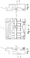
- FIGS. 1 to 5 show, as far as shown in detail, in different views a contact carrier 1 of a connector.
- This contact carrier 1 is preferably made of plastic and in a plastic injection molding process. In a corresponding number, it has contact chambers 2, wherein in this embodiment, four contact chambers 2 are shown. However, it may also be less than four or more than four contact chambers 2, which are arranged either in a row behind each other or else in two or more than two rows parallel to each other.
- the opening of the contact chambers 2 is shown, which point in the direction of a mating connector, not shown.
- the contact carrier 1 has a receiving region 4 for a locking element (to be described later).
- This at least one receiving area 4 (in the FIGS. 3 and 5 it is three receiving regions 4) preferably extends over the entire width of the contact carrier 1 and is elongated with a rectangular or square cross-section. It is also in FIG. 4 recognizable that the contact carrier 1 has a crossbar 5 with a stop element (will be explained later).
- FIGS. 6 to 10 a locking element in the form of a bolt 6 is shown.
- the latch 6, which serves for the secondary locking of the contact partners in the contact chambers 2 of the contact carrier 1, has a base part 7.
- the latch 6 is designed approximately flat with recesses and elevations.
- a latching hook 8 is present, which has a projection 9 at its free end, but need not have.
- Around the latching hook 8 around a recess 10 in the latch 6 is present, so that the free end of the latching hook 8 can move within this recess 10, when a force is exerted on it, in particular by the stop of the cross bar 5 of the contact carrier first ,
- the latch 6 at a distance from each other on contact securing elements 11, which are present in a corresponding number of the contact chambers 2 of the contact carrier 1.
- a contact-securing element 11 is present per contact partner in this exemplary embodiment.
- the contact securing elements 11 are block-shaped and formed by the flat design of the bolt 6 projecting.
- at least one linear guide of the bolt 6 is provided with which it is guided guided on the contact carrier 1.
- a first linear guide 12 and a second linear guide 13 is provided, which are both arranged on the longitudinal sides of the bolt 6. They both do not extend over the entire length of the bolt 6, but this can be conceivable for one or both linear guides 12, 13.
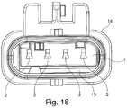
- FIGS. 11 to 14 an outer housing 14 of the connector is shown.
- the outer housing 14 has a receiving space 15 for the contact carrier 1 with its latch 6.
- a downstream side 16 of the outer housing 14 is provided, are provided on the through openings 17, from which the respective cable is led out of the outer housing 14.
- the cable in this region of the passage opening 17, the cable, in particular its outer jacket, can be sealed against the outlet side 16 of the outer housing 14.
- a further locking element is also shown above the outer housing 14, which causes the outer housing 14 to be additionally latched and locked to a mating connector (not shown) or its outer housing (in particular a so-called CPA element).
- the connector 1 can be arranged by means of the further locking element at a certain location and fixed (fixed in position), what then this locking element is designed accordingly.
- this arranged outside of the outer housing 14 element is not related to the primary and secondary locking of the contact partners in the contact chambers 2 of the connector (more precisely, the contact carrier 1).
- FIGS. 15 to 17 the assembly of the contact carrier 1, the bolt 6 and, if present, the outer housing 14 is shown.
- the latch 6 Before the contact carrier 1 is equipped with the contact partners, not shown, is in accordance with FIG. 16 the latch 6 in a first position (Vorverrast ein) arranged on the contact carrier 1. In this position of the bolt 6 in relation to the contact carrier 1, the contact securing elements 11 are in such a position that they do not hinder the insertion of a respective contact partner into its associated contact chamber 2. This means that in this position of the bolt 6, the placement of the contact partners in the respectively associated contact chambers 2 is possible. If this is done and the respective contact in its associated contact chamber 2 is also primarily locked, the latch 6 can be moved a bit far from its Vorverrast- in its Endverrast ein and fixed.
- the respective contact securing elements 11 come into operative connection with the respectively associated contact partner in the contact chamber 2 and prevent the contact partner can be moved out of its contact chamber 2, should the primary lock do not work properly.
- a second definition of the contact partner in its contact chamber (secondary lock) is realized in an advantageous manner.
- the respective contact securing element 11 is designed and arranged in the contact chamber 2 such that movement of the contact partner out of its contact chamber 2 is prevented.
- the contact securing elements 11 block-shaped.
- they may also have other geometric shapes such as pin-shaped, web-shaped or the like, if the secondary locking is ensured with this other geometric shape and can be prevented that the contact partner of its associated contact chamber 2 can be removed, especially if the primary lock not works.
- the contact carrier 1 equipped with contact partners in its contact chambers 2 and the latch 6 has been brought from its Vorverrast- in its Endverrast ein, is already a ready-to-use connector available.
- the outer housing 14 is dispensable.
- the contact carrier 1 is inserted with its latch 6 and arranged in the contact chambers 2 contact partners in the receiving space 15 of the outer housing 16 and fixed there, for example, locked, glued or the like.
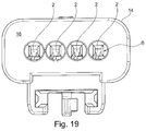
- FIGS. 18 to 19 is again shown for clarity, that the latch 6 is in its Vorverrast ein with respect to the contact carrier 1.
- the contact partners can be used in their respective contact chambers 2 and primary locked.
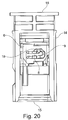
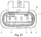
- the latch 6 can be brought from its Vorverrast- in its Endverrast ein, so that by means of the contact securing elements 11, the secondary locking is achieved. This is in the FIGS. 21 to 23 shown.
- the latch 6 has been arranged in its pre-latching position on the contact carrier 1 and was used in this arrangement in the receiving space 15 of the outer housing 14. Thereafter, the placement of the contact chambers 2 with the contact partners and the subsequent movement of the bolt 6 from its Vorverrast- in the Endverrast ein within the receiving space 15. This means that the outer housing 14 is completely closed around the receiving space 15 around.
- the outer housing 14 around the receiving space 15 around an opening, recess or the like, via which either the latch 6 is actuated or via which the latch 6 are used and brought into operative connection with the contact carrier 1 can.
- the contact carrier 1 is equipped with the contact partners and then inserted into the outer housing 14, wherein only after the bolt 6 can be brought into operative connection with the contact carrier 1 for the purpose of secondary locking.
- the reverse procedure is conceivable. That is, by the reverse procedure, the latch 6 either within the receiving space 15 in the outer housing 14 or of be brought outside or to the outside of the Endverrast- in the Vorverrast ein or even be completely detached from the contact carrier 1 to cancel the assumed secondary lock. Thereafter, the cancellation of the primary lock, for example, the defective contact partner can be removed from a contact chamber 2 and replaced. Instead of replacement in the event of a defect, the replacement of the contact partners from one type to another type is also considered.
Landscapes
- Connector Housings Or Holding Contact Members (AREA)
- Details Of Connecting Devices For Male And Female Coupling (AREA)
Applications Claiming Priority (1)
| Application Number | Priority Date | Filing Date | Title |
|---|---|---|---|
| DE102015107936 | 2015-05-20 |
Publications (2)
| Publication Number | Publication Date |
|---|---|
| EP3096410A1 true EP3096410A1 (fr) | 2016-11-23 |
| EP3096410B1 EP3096410B1 (fr) | 2018-04-11 |
Family
ID=56026718
Family Applications (1)
| Application Number | Title | Priority Date | Filing Date |
|---|---|---|---|
| EP16170465.5A Active EP3096410B1 (fr) | 2015-05-20 | 2016-05-19 | Connecteur a fiches comprenant un verrou destine au verrouillage secondaire de partenaires de contact |
Country Status (3)
| Country | Link |
|---|---|
| EP (1) | EP3096410B1 (fr) |
| DE (1) | DE102016208673A1 (fr) |
| ES (1) | ES2672129T3 (fr) |
Cited By (1)
| Publication number | Priority date | Publication date | Assignee | Title |
|---|---|---|---|---|
| WO2024077441A1 (fr) * | 2022-10-10 | 2024-04-18 | Amphenol East Asia Electronic Technology (Shenzhen) Co., Ltd. | Connecteur renforcé à grande vitesse |
Families Citing this family (2)
| Publication number | Priority date | Publication date | Assignee | Title |
|---|---|---|---|---|
| DE102017119643A1 (de) | 2016-08-26 | 2018-04-05 | Hirschmann Automotive Gmbh | Komplett abgedichteter Steckverbinder mit verbesserten Haltekräften |
| DE102019132391B4 (de) | 2019-11-28 | 2021-11-04 | Amphenol-Tuchel Electronics Gmbh | Sekundärverriegelungsvorrichtung |
Citations (6)
| Publication number | Priority date | Publication date | Assignee | Title |
|---|---|---|---|---|
| US5788540A (en) * | 1994-11-04 | 1998-08-04 | Delphi Automotive Systems Deutschland Gmbh | Electrical connecting part of a two part plug and socket connection |
| DE102008035535A1 (de) * | 2007-08-08 | 2009-02-26 | Sumitomo Wiring Systems, Ltd., Yokkaichi | Verbinder und Verfahren zum Zusammensetzen bzw. Montieren/Auseinandernehmen desselben |
| DE102010042826B3 (de) | 2010-10-22 | 2012-03-15 | Tyco Electronics Amp Gmbh | Elektrisches Steckerelement mit Kontaktsicherungsorgan und Prüfanschlag |
| WO2013073228A1 (fr) * | 2011-11-15 | 2013-05-23 | 住友電装株式会社 | Connecteur |
| DE112012003699T5 (de) * | 2011-09-06 | 2014-07-03 | Yazaki Corporation | Steckverbinder |
| EP2779317A1 (fr) * | 2011-11-09 | 2014-09-17 | Sumitomo Wiring Systems, Ltd. | Connecteur |
-
2016
- 2016-05-19 ES ES16170465.5T patent/ES2672129T3/es active Active
- 2016-05-19 EP EP16170465.5A patent/EP3096410B1/fr active Active
- 2016-05-19 DE DE102016208673.1A patent/DE102016208673A1/de not_active Withdrawn
Patent Citations (6)
| Publication number | Priority date | Publication date | Assignee | Title |
|---|---|---|---|---|
| US5788540A (en) * | 1994-11-04 | 1998-08-04 | Delphi Automotive Systems Deutschland Gmbh | Electrical connecting part of a two part plug and socket connection |
| DE102008035535A1 (de) * | 2007-08-08 | 2009-02-26 | Sumitomo Wiring Systems, Ltd., Yokkaichi | Verbinder und Verfahren zum Zusammensetzen bzw. Montieren/Auseinandernehmen desselben |
| DE102010042826B3 (de) | 2010-10-22 | 2012-03-15 | Tyco Electronics Amp Gmbh | Elektrisches Steckerelement mit Kontaktsicherungsorgan und Prüfanschlag |
| DE112012003699T5 (de) * | 2011-09-06 | 2014-07-03 | Yazaki Corporation | Steckverbinder |
| EP2779317A1 (fr) * | 2011-11-09 | 2014-09-17 | Sumitomo Wiring Systems, Ltd. | Connecteur |
| WO2013073228A1 (fr) * | 2011-11-15 | 2013-05-23 | 住友電装株式会社 | Connecteur |
Cited By (1)
| Publication number | Priority date | Publication date | Assignee | Title |
|---|---|---|---|---|
| WO2024077441A1 (fr) * | 2022-10-10 | 2024-04-18 | Amphenol East Asia Electronic Technology (Shenzhen) Co., Ltd. | Connecteur renforcé à grande vitesse |
Also Published As
| Publication number | Publication date |
|---|---|
| ES2672129T3 (es) | 2018-06-12 |
| DE102016208673A1 (de) | 2016-11-24 |
| EP3096410B1 (fr) | 2018-04-11 |
Similar Documents
| Publication | Publication Date | Title |
|---|---|---|
| DE102006016882B4 (de) | Steckverbinder | |
| EP2526591B1 (fr) | Élément de connecteur avec mécanisme de verrouillage | |
| DE102013205447B4 (de) | Elektrischer Steckverbinder sowie elektrische Steckverbindung mit einem solchen Steckverbinder | |
| DE102011051291A1 (de) | Steckverbinder mit Kammerblock und Kontaktsicherung | |
| WO2014183821A1 (fr) | Connecteur | |
| DE102015201089A1 (de) | Zwischengehäuse mit einer CPA-Aufnahme und Steckverbindersysteme umfassend ein solches | |
| EP3252884A1 (fr) | Prise de voyage compacte | |
| EP3096410B1 (fr) | Connecteur a fiches comprenant un verrou destine au verrouillage secondaire de partenaires de contact | |
| EP3787128A1 (fr) | Raccordement enfichable | |
| DE202014010345U1 (de) | Anschlussleiste für ein Elektronikgerät | |
| EP3073577B1 (fr) | Fiche male, connecteur a fiches et procede de fabrication d'une fiche male | |
| DE1665644C3 (de) | Elektrische Steckvorrichtung | |
| WO2019057519A1 (fr) | Auxiliaire d'insertion pour connecteurs électriques, avec direction de coulissement dans la direction d'enfichage | |
| EP0703641B1 (fr) | Elément de connecteur électrique | |
| EP2067212B1 (fr) | Connecteur à fiches électrique avec guidage | |
| DE112013002664T5 (de) | Schutzabdeckung für Elektrodraht | |
| EP2713450B1 (fr) | Connexion à fiche et procédé de fonctionnement d'un telle connexion | |
| DE102016217456B3 (de) | Anordnung für einen elektrischen Steckverbinder sowie Steckverbinder mit einem Kontaktgehäuse, Umgehäuse und Sicherungselement | |
| DE102005030264A1 (de) | Geschlossenes Gehäuse für ein Verriegelungselement einer Steckverbindung | |
| EP2587595B1 (fr) | Connexion à fiche et procédé d'actionnement d'une connexion à fiche pour applications haute tension | |
| WO2011023778A1 (fr) | Connecteur électrique | |
| DE102014109477A1 (de) | Verriegelbare Steckverbindung | |
| DE202011000750U1 (de) | Steckverbindungsanordnung für elektrische Leiter | |
| EP1679767A1 (fr) | Connecteur électrique | |
| DE19650098A1 (de) | Geringkopplungskraft-Steckverbinder |
Legal Events
| Date | Code | Title | Description |
|---|---|---|---|
| PUAI | Public reference made under article 153(3) epc to a published international application that has entered the european phase |
Free format text: ORIGINAL CODE: 0009012 |
|
| AK | Designated contracting states |
Kind code of ref document: A1 Designated state(s): AL AT BE BG CH CY CZ DE DK EE ES FI FR GB GR HR HU IE IS IT LI LT LU LV MC MK MT NL NO PL PT RO RS SE SI SK SM TR |
|
| AX | Request for extension of the european patent |
Extension state: BA ME |
|
| STAA | Information on the status of an ep patent application or granted ep patent |
Free format text: STATUS: REQUEST FOR EXAMINATION WAS MADE |
|
| 17P | Request for examination filed |
Effective date: 20170523 |
|
| RBV | Designated contracting states (corrected) |
Designated state(s): AL AT BE BG CH CY CZ DE DK EE ES FI FR GB GR HR HU IE IS IT LI LT LU LV MC MK MT NL NO PL PT RO RS SE SI SK SM TR |
|
| GRAP | Despatch of communication of intention to grant a patent |
Free format text: ORIGINAL CODE: EPIDOSNIGR1 |
|
| STAA | Information on the status of an ep patent application or granted ep patent |
Free format text: STATUS: GRANT OF PATENT IS INTENDED |
|
| RIC1 | Information provided on ipc code assigned before grant |
Ipc: H01R 13/502 20060101ALI20171011BHEP Ipc: H01R 13/436 20060101AFI20171011BHEP |
|
| INTG | Intention to grant announced |
Effective date: 20171107 |
|
| GRAS | Grant fee paid |
Free format text: ORIGINAL CODE: EPIDOSNIGR3 |
|
| GRAA | (expected) grant |
Free format text: ORIGINAL CODE: 0009210 |
|
| STAA | Information on the status of an ep patent application or granted ep patent |
Free format text: STATUS: THE PATENT HAS BEEN GRANTED |
|
| AK | Designated contracting states |
Kind code of ref document: B1 Designated state(s): AL AT BE BG CH CY CZ DE DK EE ES FI FR GB GR HR HU IE IS IT LI LT LU LV MC MK MT NL NO PL PT RO RS SE SI SK SM TR |
|
| REG | Reference to a national code |
Ref country code: GB Ref legal event code: FG4D Free format text: NOT ENGLISH |
|
| REG | Reference to a national code |
Ref country code: CH Ref legal event code: EP |
|
| REG | Reference to a national code |
Ref country code: AT Ref legal event code: REF Ref document number: 988971 Country of ref document: AT Kind code of ref document: T Effective date: 20180415 |
|
| REG | Reference to a national code |
Ref country code: IE Ref legal event code: FG4D Free format text: LANGUAGE OF EP DOCUMENT: GERMAN |
|
| REG | Reference to a national code |
Ref country code: DE Ref legal event code: R096 Ref document number: 502016000820 Country of ref document: DE |
|
| REG | Reference to a national code |
Ref country code: FR Ref legal event code: PLFP Year of fee payment: 3 |
|
| REG | Reference to a national code |
Ref country code: ES Ref legal event code: FG2A Ref document number: 2672129 Country of ref document: ES Kind code of ref document: T3 Effective date: 20180612 |
|
| REG | Reference to a national code |
Ref country code: RO Ref legal event code: EPE |
|
| REG | Reference to a national code |
Ref country code: NL Ref legal event code: MP Effective date: 20180411 |
|
| REG | Reference to a national code |
Ref country code: LT Ref legal event code: MG4D |
|
| PG25 | Lapsed in a contracting state [announced via postgrant information from national office to epo] |
Ref country code: NL Free format text: LAPSE BECAUSE OF FAILURE TO SUBMIT A TRANSLATION OF THE DESCRIPTION OR TO PAY THE FEE WITHIN THE PRESCRIBED TIME-LIMIT Effective date: 20180411 |
|
| PG25 | Lapsed in a contracting state [announced via postgrant information from national office to epo] |
Ref country code: BG Free format text: LAPSE BECAUSE OF FAILURE TO SUBMIT A TRANSLATION OF THE DESCRIPTION OR TO PAY THE FEE WITHIN THE PRESCRIBED TIME-LIMIT Effective date: 20180711 Ref country code: FI Free format text: LAPSE BECAUSE OF FAILURE TO SUBMIT A TRANSLATION OF THE DESCRIPTION OR TO PAY THE FEE WITHIN THE PRESCRIBED TIME-LIMIT Effective date: 20180411 Ref country code: SE Free format text: LAPSE BECAUSE OF FAILURE TO SUBMIT A TRANSLATION OF THE DESCRIPTION OR TO PAY THE FEE WITHIN THE PRESCRIBED TIME-LIMIT Effective date: 20180411 Ref country code: LT Free format text: LAPSE BECAUSE OF FAILURE TO SUBMIT A TRANSLATION OF THE DESCRIPTION OR TO PAY THE FEE WITHIN THE PRESCRIBED TIME-LIMIT Effective date: 20180411 Ref country code: AL Free format text: LAPSE BECAUSE OF FAILURE TO SUBMIT A TRANSLATION OF THE DESCRIPTION OR TO PAY THE FEE WITHIN THE PRESCRIBED TIME-LIMIT Effective date: 20180411 Ref country code: NO Free format text: LAPSE BECAUSE OF FAILURE TO SUBMIT A TRANSLATION OF THE DESCRIPTION OR TO PAY THE FEE WITHIN THE PRESCRIBED TIME-LIMIT Effective date: 20180711 Ref country code: PL Free format text: LAPSE BECAUSE OF FAILURE TO SUBMIT A TRANSLATION OF THE DESCRIPTION OR TO PAY THE FEE WITHIN THE PRESCRIBED TIME-LIMIT Effective date: 20180411 |
|
| PG25 | Lapsed in a contracting state [announced via postgrant information from national office to epo] |
Ref country code: RS Free format text: LAPSE BECAUSE OF FAILURE TO SUBMIT A TRANSLATION OF THE DESCRIPTION OR TO PAY THE FEE WITHIN THE PRESCRIBED TIME-LIMIT Effective date: 20180411 Ref country code: LV Free format text: LAPSE BECAUSE OF FAILURE TO SUBMIT A TRANSLATION OF THE DESCRIPTION OR TO PAY THE FEE WITHIN THE PRESCRIBED TIME-LIMIT Effective date: 20180411 Ref country code: HR Free format text: LAPSE BECAUSE OF FAILURE TO SUBMIT A TRANSLATION OF THE DESCRIPTION OR TO PAY THE FEE WITHIN THE PRESCRIBED TIME-LIMIT Effective date: 20180411 Ref country code: GR Free format text: LAPSE BECAUSE OF FAILURE TO SUBMIT A TRANSLATION OF THE DESCRIPTION OR TO PAY THE FEE WITHIN THE PRESCRIBED TIME-LIMIT Effective date: 20180712 |
|
| PG25 | Lapsed in a contracting state [announced via postgrant information from national office to epo] |
Ref country code: PT Free format text: LAPSE BECAUSE OF FAILURE TO SUBMIT A TRANSLATION OF THE DESCRIPTION OR TO PAY THE FEE WITHIN THE PRESCRIBED TIME-LIMIT Effective date: 20180813 |
|
| REG | Reference to a national code |
Ref country code: DE Ref legal event code: R097 Ref document number: 502016000820 Country of ref document: DE |
|
| REG | Reference to a national code |
Ref country code: BE Ref legal event code: MM Effective date: 20180531 |
|
| PG25 | Lapsed in a contracting state [announced via postgrant information from national office to epo] |
Ref country code: EE Free format text: LAPSE BECAUSE OF FAILURE TO SUBMIT A TRANSLATION OF THE DESCRIPTION OR TO PAY THE FEE WITHIN THE PRESCRIBED TIME-LIMIT Effective date: 20180411 Ref country code: SK Free format text: LAPSE BECAUSE OF FAILURE TO SUBMIT A TRANSLATION OF THE DESCRIPTION OR TO PAY THE FEE WITHIN THE PRESCRIBED TIME-LIMIT Effective date: 20180411 Ref country code: MC Free format text: LAPSE BECAUSE OF FAILURE TO SUBMIT A TRANSLATION OF THE DESCRIPTION OR TO PAY THE FEE WITHIN THE PRESCRIBED TIME-LIMIT Effective date: 20180411 Ref country code: DK Free format text: LAPSE BECAUSE OF FAILURE TO SUBMIT A TRANSLATION OF THE DESCRIPTION OR TO PAY THE FEE WITHIN THE PRESCRIBED TIME-LIMIT Effective date: 20180411 |
|
| PLBE | No opposition filed within time limit |
Free format text: ORIGINAL CODE: 0009261 |
|
| STAA | Information on the status of an ep patent application or granted ep patent |
Free format text: STATUS: NO OPPOSITION FILED WITHIN TIME LIMIT |
|
| REG | Reference to a national code |
Ref country code: IE Ref legal event code: MM4A |
|
| PG25 | Lapsed in a contracting state [announced via postgrant information from national office to epo] |
Ref country code: SM Free format text: LAPSE BECAUSE OF FAILURE TO SUBMIT A TRANSLATION OF THE DESCRIPTION OR TO PAY THE FEE WITHIN THE PRESCRIBED TIME-LIMIT Effective date: 20180411 |
|
| 26N | No opposition filed |
Effective date: 20190114 |
|
| PG25 | Lapsed in a contracting state [announced via postgrant information from national office to epo] |
Ref country code: LU Free format text: LAPSE BECAUSE OF NON-PAYMENT OF DUE FEES Effective date: 20180519 |
|
| PG25 | Lapsed in a contracting state [announced via postgrant information from national office to epo] |
Ref country code: IE Free format text: LAPSE BECAUSE OF NON-PAYMENT OF DUE FEES Effective date: 20180519 |
|
| PG25 | Lapsed in a contracting state [announced via postgrant information from national office to epo] |
Ref country code: SI Free format text: LAPSE BECAUSE OF FAILURE TO SUBMIT A TRANSLATION OF THE DESCRIPTION OR TO PAY THE FEE WITHIN THE PRESCRIBED TIME-LIMIT Effective date: 20180411 Ref country code: BE Free format text: LAPSE BECAUSE OF NON-PAYMENT OF DUE FEES Effective date: 20180531 |
|
| REG | Reference to a national code |
Ref country code: CH Ref legal event code: PL |
|
| PG25 | Lapsed in a contracting state [announced via postgrant information from national office to epo] |
Ref country code: CH Free format text: LAPSE BECAUSE OF NON-PAYMENT OF DUE FEES Effective date: 20190531 Ref country code: LI Free format text: LAPSE BECAUSE OF NON-PAYMENT OF DUE FEES Effective date: 20190531 Ref country code: MT Free format text: LAPSE BECAUSE OF FAILURE TO SUBMIT A TRANSLATION OF THE DESCRIPTION OR TO PAY THE FEE WITHIN THE PRESCRIBED TIME-LIMIT Effective date: 20180411 |
|
| PG25 | Lapsed in a contracting state [announced via postgrant information from national office to epo] |
Ref country code: TR Free format text: LAPSE BECAUSE OF FAILURE TO SUBMIT A TRANSLATION OF THE DESCRIPTION OR TO PAY THE FEE WITHIN THE PRESCRIBED TIME-LIMIT Effective date: 20180411 |
|
| PG25 | Lapsed in a contracting state [announced via postgrant information from national office to epo] |
Ref country code: CY Free format text: LAPSE BECAUSE OF FAILURE TO SUBMIT A TRANSLATION OF THE DESCRIPTION OR TO PAY THE FEE WITHIN THE PRESCRIBED TIME-LIMIT Effective date: 20180411 Ref country code: HU Free format text: LAPSE BECAUSE OF FAILURE TO SUBMIT A TRANSLATION OF THE DESCRIPTION OR TO PAY THE FEE WITHIN THE PRESCRIBED TIME-LIMIT; INVALID AB INITIO Effective date: 20160519 Ref country code: MK Free format text: LAPSE BECAUSE OF NON-PAYMENT OF DUE FEES Effective date: 20180411 |
|
| PG25 | Lapsed in a contracting state [announced via postgrant information from national office to epo] |
Ref country code: IS Free format text: LAPSE BECAUSE OF FAILURE TO SUBMIT A TRANSLATION OF THE DESCRIPTION OR TO PAY THE FEE WITHIN THE PRESCRIBED TIME-LIMIT Effective date: 20180811 |
|
| REG | Reference to a national code |
Ref country code: AT Ref legal event code: MM01 Ref document number: 988971 Country of ref document: AT Kind code of ref document: T Effective date: 20210519 |
|
| PG25 | Lapsed in a contracting state [announced via postgrant information from national office to epo] |
Ref country code: AT Free format text: LAPSE BECAUSE OF NON-PAYMENT OF DUE FEES Effective date: 20210519 |
|
| PGFP | Annual fee paid to national office [announced via postgrant information from national office to epo] |
Ref country code: RO Payment date: 20230516 Year of fee payment: 8 Ref country code: IT Payment date: 20230526 Year of fee payment: 8 Ref country code: FR Payment date: 20230526 Year of fee payment: 8 Ref country code: DE Payment date: 20230519 Year of fee payment: 8 Ref country code: CZ Payment date: 20230515 Year of fee payment: 8 |
|
| PGFP | Annual fee paid to national office [announced via postgrant information from national office to epo] |
Ref country code: GB Payment date: 20230524 Year of fee payment: 8 Ref country code: ES Payment date: 20230725 Year of fee payment: 8 |