EP3095727A1 - Von hand ausdrückbares mehrkomponentenbehältnis - Google Patents
Von hand ausdrückbares mehrkomponentenbehältnis Download PDFInfo
- Publication number
- EP3095727A1 EP3095727A1 EP16167863.6A EP16167863A EP3095727A1 EP 3095727 A1 EP3095727 A1 EP 3095727A1 EP 16167863 A EP16167863 A EP 16167863A EP 3095727 A1 EP3095727 A1 EP 3095727A1
- Authority
- EP
- European Patent Office
- Prior art keywords
- component container
- chambers
- component
- collection point
- container
- Prior art date
- Legal status (The legal status is an assumption and is not a legal conclusion. Google has not performed a legal analysis and makes no representation as to the accuracy of the status listed.)
- Granted
Links
Images


Classifications
-
- B—PERFORMING OPERATIONS; TRANSPORTING
- B65—CONVEYING; PACKING; STORING; HANDLING THIN OR FILAMENTARY MATERIAL
- B65D—CONTAINERS FOR STORAGE OR TRANSPORT OF ARTICLES OR MATERIALS, e.g. BAGS, BARRELS, BOTTLES, BOXES, CANS, CARTONS, CRATES, DRUMS, JARS, TANKS, HOPPERS, FORWARDING CONTAINERS; ACCESSORIES, CLOSURES, OR FITTINGS THEREFOR; PACKAGING ELEMENTS; PACKAGES
- B65D81/00—Containers, packaging elements, or packages, for contents presenting particular transport or storage problems, or adapted to be used for non-packaging purposes after removal of contents
- B65D81/32—Containers, packaging elements, or packages, for contents presenting particular transport or storage problems, or adapted to be used for non-packaging purposes after removal of contents for packaging two or more different materials which must be maintained separate prior to use in admixture
- B65D81/3261—Flexible containers having several compartments
- B65D81/3266—Flexible containers having several compartments separated by a common rupturable seal, a clip or other removable fastening device
Definitions
- the invention relates to a hand-expressible multi-component container for separate storage flowable components that can be expressed by squeezing the multi-component container by hand together from the multi-component container, with the features of the preamble of claim 1.
- the expressions for example, by rolling the multi-component container from one end as possible with toothpaste or other tubes.
- “Expressions by hand” expresses that the common expression of the flowable components contained separately in the multi-component container is possible without tools. Other ways of squeezing or general spreading, even with tools or devices, are not excluded.
- Flowable means that the components are, for example, liquid or pasty. It may be, for example, a binder and a hardener of a two-component adhesive or resin. Such components must be kept separate from each other until use and usually kept airtight. For use, the components are mixed and then bind, which can also be understood as curing. After mixing and before setting, the components must be shipped to an application site, such as a splice.
- a hand-expressible two-component container for separate storage and compressible by compressing the two-component container of manually expressible, flowable components is known from the U.S. Patent 4,952,068 .
- the known two-component container has two mutually arranged plates with bulges, which form two adjacent chambers for two separately stored components, a mixing chamber and an outlet.
- the two plates are connected to each other at the periphery and between the two chambers, for example by welded or glued seams. Passages from the chambers to the mixing chamber are sealed with membranes, so that the Components airtight and separated from each other in the two adjacent chambers of the two-component container are included.
- the two-component container In the mixing chamber, the two-component container has obstacles that must be flowed around during the expressions of the components to mix the components.
- the two chambers of the known two-component container can be compressed by hand, whereby the membranes that close the chambers are destroyed and the two components flow from the two chambers through the mixing chamber into the outlet.
- the two chambers can also be expressed by rolling up the two-component container beginning at an end remote from the outlet. To open the known two-component container, a tip of the outlet must be cut off or torn off before being pressed out.
- Another two- or multi-component container discloses the European patent EP 1 843 952 B1 , in which also two plates with bulges arranged on each other and are welded around the circumference around the write-offs around. Between the plates a film is arranged as a partition, which closes the bulges tight. The bulges closed with the partition wall form chambers in which the components are contained separately.
- the known two-component container on an outlet tube, which is formed by two half-tubes of the two successive plates, which are laterally welded together along the outlet tube.
- a static mixer is arranged, which has an opening mandrel with two points at an end facing the bulges.
- the opening mandrel of the static mixer destroys the dividing wall between the two chambers, after which the chambers formed by the bulges can be manually expressed.
- the components contained in the chambers flow together when expressing the two-component container and flow through the outlet tube with the static mixer, in which they are mixed.
- the object of the invention is to propose an alternative, manually expressible multi-component container.
- the hand-expressible multi-component container according to the invention for separate storage and by compressing the multi-component container by hand together expressible, flowable components with the features of claim 1 comprises a compressible chamber for each component, each chamber communicating through a chamber outlet with a collection point where the components flow together from the chambers, when the chambers are compressed to express the multicomponent container or, for example, the multicomponent container is removed starting at a chamber outlets Being rolled up.
- An openable shut-off body similar to a valve in a closed position, separates the chamber outlets from the collection point so that the components in the chambers are separated from each other and preferably sealed airtight in the chambers.
- the chamber outlets communicate with the collection point.
- the shut-off body of the multi-component container according to the invention need not or should not again be movable into the closed position.
- the shut-off body is moved from the closed position to the open position, thereby opening the chamber outlets.
- the shut-off body is movably arranged in the collection point, which may form a kind of valve housing or a type of valve seat with which the shut-off body cooperates.
- the multi-component container to a static mixer, which is slidably disposed in a container outlet of the multi-component container, which communicates with the collection point.
- the container outlet is tubular or tubular and the static mixer rod-shaped.
- Static mixers for mixing two or more flowable components are known. They usually have juxtaposed, for example screw, lamella or lattice-shaped elements that repeatedly separate the components as they flow through the static mixer and merge again, so that the components are mixed.
- the static mixer to the shut-off, which can be opened by a movement of the static mixer in the container outlet, in particular by moving.
- the static mixer is pulled out a piece, ie moved in the container outlet from the collection point, whereby the shut-off is moved to the open position and the components can be expressed from the chambers.
- the flow Components from the chambers through the chamber outlets to the collection point and from there through the static mixer in the container outlet, where they are mixed and exit at the end.
- the static mixer can no longer be moved back against the masses in the chamber outlets and the collection point and the chambers can no longer be closed.
- This embodiment of the invention allows a simple and inexpensive and easy to handle without tools multi-component container for separate storage of flowable components that can be expressed by moving the shut-off in the open position by moving the static mixer in the container outlet by hand and mixed in static mixer so that they ready to use exit from the container outlet.
- the chambers of the multi-component container according to the invention are arranged one above the other.
- the mixing ratio of the components preferably corresponds to a ratio of volumes of the chambers, which may have the same or different volumes. Different volumes are possible with congruent chambers by different chamber heights.
- an embodiment of the invention provides that the chambers have filling openings, which are preferably arranged offset.
- the filling openings are not identical to the chamber outlets.
- the multi-component container can be filled after its production, staggered openings facilitate filling. After filling, the filling openings are closed, for example by gluing or a weld. It is also conceivable a Wickelfalz at one end of the multi-component container for closing the filling openings after filling the chambers.
- the multi-component container has mutually arranged walls with bulges that form the chambers, chamber outlets, the collection point and possibly the container outlet and / or the filling openings of the chambers.
- the bulges for the chambers and the Collection point for example, trough-shaped, for the chamber outlets and, if available, the container outlet and / or the filling openings of the chambers are, for example, half-tube or semi-tubular.
- the walls may be, for example, plastic films, plastic plates or metal foils on which the bulges are made for example by thermoforming or deep drawing.
- the walls are placed on each other and connected circumferentially, for example glued or welded. This allows a low-cost production of the multi-component container.
- a further development of the invention provides at least one in particular level partition between the bulges of the walls, which forms the chambers together with the bulges.
- the partition wall is for example a flat foil or plate, which is arranged in the region of the chambers between the walls with the bulges.
- an embodiment of the invention provides that the multi-chamber container has a plurality of identical walls with the same bulges, which does not exclude additional other walls and / or partitions. Several identical parts reduce the production costs. Staggered filling openings can be achieved by offsetting the filling openings to one side. If the walls with mutually protruding bulges arranged on each other, the filling openings are offset to different sides.
- the multicomponent ratio according to the invention is in particular a two-component container with two separate chambers.
- the multi-component container for chemical anchors is provided in the construction sector, the chambers in this case contain components of a mortar, for example a synthetic resin multi-component mortar.
- a mortar for example a synthetic resin multi-component mortar.
- an anchor usually an anchor rod, with a hardening mass which, even if made of synthetic resin, is also referred to as mortar, is fixed in a drill or other hole in concrete, stone, masonry or other anchorage becomes.
- the multi-component container is provided for an adhesive.
- inventive multi-component container 1 is used for separate storage and common expressions flowable components.
- the illustrated embodiment is provided for two components, namely a binder and a hardener of a two-component synthetic resin mortar, ie it is a two-component container.
- the multi-component container 1 is designed like a tube, but with several - in the exemplary embodiment two - separate, yet to be explained chambers for separate storage of the components. By squeezing the chambers of the multi-component container 1 by hand, the components are expressed from the multi-component container 1. Instead of compressing the multicomponent container 1, it may also be rolled up beginning at an end remote from an outlet to expel the components from the chambers.
- the multi-component container 1 has two walls 2 with trough-shaped bulges 3 and grooves and a partition 4, which, as in FIG. 2 to stand, arranged on top of each other and welded together. Furthermore, the multicomponent container 1 has a static mixer 14, which in FIG. 2 not drawn.
- the walls 2 are thermoformed plastic films and the partition 4 is a flat plastic film.
- the trough-shaped bulges 3 form the chambers 5 of the multi-component container 1 for the separate storage of the components.
- the chambers 5 are closed with the partition 4, which completely covers the chambers 5 and the chambers 5 is welded to the walls 3 enclosing. It can also be provided for each wall 3 separate partitions 4 (not shown) to close the chambers 5 individually and to fill and then to weld the already welded to the partitions 4 walls 3 for multi-component container 1.
- the dividing wall 4 is recessed, so that the components expressed from the chambers 5 through the opposite chamber outlets 7 flow together in the collecting point 6.
- From the collection point 6 grooves lead as container outlet 8 in the longitudinal center of the walls 2 to the outside.
- the container outlet 8 is formed as a straight, semi-tubular groove in the walls 2, so that results in a straight, tubular container outlet 8 by the arrangement of the walls 2 on each other.
- the partition 4 is also recessed or not present.
- the filling openings 9 are also formed as a semi-cylindrical grooves in the walls 2.
- the filling openings 9 are arranged offset as well as the chamber outlets 7 to one side, so that they are offset from each other on the multi-component container 1.
- the walls 2 are the same parts that are placed on each other for welding to the multi-component container 1 forming tube with the interposition of the partition 4, as in FIG. 2 you can see.
- the two walls 2 are made as identical parts, ie the filling openings 9 and the chamber outlets 7 are offset on the walls 2 to the same side.
- the hollow sides of the chambers 5, etc. facing each other, ie, one of the walls 2 is reversed, whereby the multi-component container 1, the filling openings 9 and the chamber outlets 7 are offset to opposite sides.
- left side is a raised side of a wall 2 and the hollow side of the other wall 2 shown on the right.
- FIGS. 3 and 4 Shown by dashed lines are welds 10 for welding the walls 2 and the partition 4 to the multi-component container 1.
- the chambers 5, the collection point 6 and the container outlet 8 are congruent to each other.
- the static mixer 14 is rod-shaped and veschiebbar in Be Camillnisausslass 8. He has screw and / or lamellar elements that divide the components expressed from the chambers 5 when flowing through multiple times and merge again and mix in this way. Such static mixer 14 are known and will not be explained further here.
- the static mixer 14 has at one end a circular disc-shaped shut-off body 11 with a cylindrical projection 12 which is located in the collection point 6, wherein the cylindrical projection 12 of the shut-off 11 projects into a cylindrical extension 13 of the collection point 6 between the Kammerauslässen 7, the opposite sides in the extension 13 of the collection point 6 open.
- the shut-off body 11 with its cylindrical projection 12 act comparable to a shut-off valve and form together with the collection point 6 and its extension 13 a kind of valve: In the closed position, the FIG. 3 shows, are the shut-off 11 at one of the chambers 5 near the end of the collection point 6 and the cylindrical projection 12 protrudes into the extension 13 of the collection point 6.
- shut-off valve 11 closes the chamber outlets 7, so that the chambers 5 separated from each other and are hermetically sealed.
- the static mixer 14 a piece pulled out of the container outlet 8, whereby the shut-off 11 of the chambers 5 near the end of the collection point 6 is removed and the cylindrical projection 12 emerges from the extension 13 of the collection point 6.
- the chamber outlets 7 are now open to the collection point 6, so that the components can be expressed from the chambers 5 and flow through the chamber outlets 7 into the collection point 6.
- shut-off body 11 Through a hollow shut-off body 11 and / or through holes in the shut-off body 11, the components flow through the shut-off body 11 or the shut-off body 11 past into the static mixer 14, where they are mixed and at a distal end of the chambers 5 from the static mixer 14 and the container outlet. 8 escape.
- the congruently arranged chambers 5 are expressed together like a tube by squeezing by hand together.
- the multi-component container 1 can be rolled up at the end remote from the container outlet 8 for expressing purposes.
- the walls 2 and the partition wall 4 can also be connected other than by welding, for example by gluing.
- the filling openings 9 remain open when welding the walls 2 and the partition wall 4, so that the chambers 5 can be filled with the components. After filling the filling openings 9 are hermetically sealed, for example, welded or taped. It is also possible to produce the multi-component container 1 from metal foils or a mixture of metal and plastic foils. The walls 2 are deep-drawn in this case.
- the filling openings 9 can also be closed by a spiral fold at the chamber-side end of the multi-component container 1 in this case.
- the walls 2 and the partition wall 4 or partitions 4 also consist of a film which is folded so that the walls 2 face each other with their hollow sides facing each other and enters the partition 4 or partitions 4 between the walls 2 (not shown).
Landscapes
- Engineering & Computer Science (AREA)
- Mechanical Engineering (AREA)
- Package Specialized In Special Use (AREA)
- Tubes (AREA)
Abstract
Description
- Die Erfindung betrifft ein von Hand ausdrückbares Mehrkomponentenbehältnis zum getrennten Aufbewahren fließfähiger Komponenten, die durch Zusammendrücken des Mehrkomponentenbehältnis von Hand gemeinsam aus dem Mehrkomponentenbehältnis ausdrückbar sind, mit den Merkmalen des Oberbegriffs des Anspruchs 1. Das Ausdrücken ist beispielsweise auch durch Aufrollen des Mehrkomponentenbehältnis von einem Ende her wie beispielsweise bei Zahnpasta- oder sonstigen Tuben möglich. "Ausdrücken von Hand" bringt zum Ausdruck, dass das gemeinsame Ausdrücken der getrennt im Mehrkomponentenbehältnis enthaltenen fließfähigen Komponenten ohne Werkzeug möglich ist. Andere Möglichkeiten des Ausdrückens oder allgemein Ausbringens, auch mit Werkzeug oder Vorrichtungen, sind nicht ausgeschlossen.
- Fließfähig bedeutet, dass die Komponenten beispielsweise flüssig oder pastös sind. Es kann sich beispielsweise um einen Binder und einen Härter eines Zweikomponentenklebers oder Harzes handeln. Solche Komponenten müssen bis zum Gebrauch voneinander getrennt und meist auch luftdicht verschlossen aufbewahrt werden. Zum Gebrauch werden die Komponenten gemischt und binden dann ab, was auch als Aushärten aufgefasst werden kann. Nach dem Mischen und vor dem Abbinden müssen die Komponenten an einen Anwendungsort verbracht werden, beispielsweise an eine Klebestelle.
- Ein von Hand ausdrückbares Zweikomponentenbehältnis zum getrennten Aufbewahren und durch Zusammendrücken des Zweikomponentenbehältnis von Hand gemeinsam ausdrückbaren, fließfähiger Komponenten ist bekannt aus dem
US-Patent 4,952,068 . Das bekannte Zweikomponentenbehältnis weist zwei aufeinander angeordnete Platten mit Ausbauchungen auf, die zwei nebeneinander befindliche Kammern für zwei getrennt aufzubewahrende Komponenten, eine Mischkammer und einen Auslass bilden. Die beiden Platten sind am Umfang und zwischen den beiden Kammern beispielsweise durch geschweißte oder geklebte Nähte miteinander verbunden. Durchlässe von den Kammern zur Mischkammer sind mit Membranen verschlossen, so dass die Komponenten luftdicht und voneinander getrennt in den beiden nebeneinander angeordneten Kammern des Zweikomponentenbehältnis enthalten sind. In der Mischkammer weist das Zweikomponentenbehältnis Hindernisse auf, die beim Ausdrücken von den Komponenten umströmt werden müssen, um die Komponenten zu mischen. Die beiden Kammern des bekannten Zweikomponentenbehältnis lassen sich von Hand zusammendrücken, wodurch die Membranen, die die Kammern verschließen, zerstört werden und die beiden Komponenten aus den beiden Kammern durch die Mischkammer in den Auslass fließen. Die beiden Kammern lassen sich auch durch Aufrollen des Zweikomponentenbehältnis beginnend an einem dem Auslass fernen Ende ausdrücken. Zum Öffnen des bekannten Zweikomponentenbehältnis muss vor dem Auspressen eine Spitze des Auslass abgeschnitten oder abgerissen werden. - Ein weiteres Zwei- oder Mehrkomponentenbehältnis offenbart das Europäische Patent
EP 1 843 952 B1 , bei dem ebenfalls zwei Platten mit Ausbauchungen aufeinander angeordnet und am Umfang um die Ausbuchungen herum verschweißt sind. Zwischen den Platten ist eine Folie als Trennwand angeordnet, die die Ausbauchungen dicht verschließt. Die mit der Trennwand verschlossenen Ausbauchungen bilden Kammern, in denen die Komponenten getrennt voneinander enthalten sind. In einer Verlängerung der Ausbauchungen weist das bekannte Zweikomponentenbehältnis ein Auslassrohr auf, das von zwei Halbrohren der beiden aufeinander angeordneten Platten gebildet ist, die seitlich entlang des Auslassrohrs miteinander verschweißt sind. In dem Auslassrohr ist ein Statikmischer angeordnet, der an einem den Ausbauchungen zugewandten Ende einen Öffnungsdorn mit zwei Spitzen aufweist. Durch Knicken des Auslassrohrs mit dem in ihm angeordneten Statikmischer gegenüber den Ausbauchungen zerstört der Öffnungsdorn des Statikmischers die Trennwand zwischen den beiden Kammern, wonach die von den Ausbauchungen gebildeten Kammern von Hand ausgedrückt werden können. Die in den Kammern enthaltenen Komponenten fließen beim Ausdrücken des Zweikomponentenbehältnis zusammen und durchfließen das Auslassrohr mit dem Statikmischer, in dem sie durchmischt werden. - Aufgabe der Erfindung ist ein alternatives, von Hand ausdrückbares Mehrkomponentenbehältnis vorzuschlagen.
- Das erfindungsgemäße, von Hand ausdrückbare Mehrkomponentenbehältnis zum getrennten Aufbewahren und durch Zusammendrücken des Mehrkomponentenbehältnis von Hand gemeinsam ausdrückbaren, fließfähigen Komponenten mit den Merkmalen des Anspruchs 1 weist für jede Komponente eine zusammendrückbare Kammer auf, wobei jede Kammer durch einen Kammerauslass mit einer Sammelstelle kommuniziert, wo die Komponenten aus den Kammern zusammenfließen, wenn die Kammern zum Ausdrücken des Mehrkomponentenbehältnis zusammengedrückt oder beispielsweise auch das Mehrkomponentenbehältnis beginnend an einem den Kammerauslässen fernen Ende aufgerollt wird. Ein öffenbarer Absperrkörper trennt vergleichbar einem Ventil in einer geschlossenen Stellung die Kammerauslässe von der Sammelstelle, so dass die Komponenten in den Kammern voneinander getrennt und vorzugsweise luftdicht in den Kammern eingeschlossen sind. Wird der Absperrkörper, vorzugsweise von Hand, in eine offene Stellung bewegt, kommunizieren die Kammerauslässe mit der Sammelstelle. Im Unterschied zu einem Ventil muss bzw. soll der Absperrkörper des erfindungsgemäßen Mehrkomponentenbehältnis nicht wieder in die geschlossene Stellung bewegbar sein. Zum Gebrauch wird der Absperrkörper von der geschlossenen Stellung in die offene Stellung bewegt und damit die Kammerauslässe geöffnet. Durch anschließendes Zusammendrücken des Mehrkomponentenbehältnis bzw. seiner Kammern werden die getrennt in den Kammern enthaltenen Komponenten ausgedrückt und fließen durch die Kammerauslässe in die Sammelstelle zusammen.
- Vorzugsweise ist der Absperrkörper beweglich in der Sammelstelle angeordnet, die eine Art Ventilgehäuse bzw. eine Art Ventilsitz bilden kann, mit dem der Absperrkörper zusammenwirkt.
- In bevorzugter Ausgestaltung der Erfindung weist das Mehrkomponentenbehältnis einen Statikmischer auf, der verschiebbar in einem Behältnisauslass des Mehrkomponentenbehältnis angeordnet ist, der mit der Sammelstelle kommuniziert. Beispielsweise ist der Behältnisauslass schlauch- oder rohrförmig und der Statikmischer stangenförmig. Statikmischer zum Mischen von zwei oder mehr fließfähigen Komponenten sind bekannt. Sie weisen meist aneinander gereihte, beispielsweise schrauben-, lamellen- oder auch gitterförmige Elemente auf, die die Komponenten beim Durchströmen des Statikmischers wiederholt trennen und wieder zusammenführen, so dass die Komponenten gemischt werden. Erfindungsgemäß weist der Statikmischer den Absperrkörper auf, der durch eine Bewegung des Statikmischers im Behältnisauslass, insbesondere durch Verschieben, öffenbar ist. Beispielsweise wird der Statikmischer ein Stück herausgezogen, d. h. im Behältnisauslass von der Sammelstelle weg verschoben, wodurch der Absperrkörper in die offene Stellung bewegt wird und die Komponenten aus den Kammern ausgedrückt werden können. Durch das Ausdrücken strömen die Komponenten aus den Kammern durch die Kammerauslässe in die Sammelstelle und von dort weiter durch den Statikmischer im Behältnisauslass, wo sie gemischt werden und am Ende austreten. Vorzugsweise lässt sich der Statikmischer nach dem Ausdrücken oder einem teilweisen Ausdrücken der Kammern des Mehrkomponentenbehältnis nicht mehr gegen die Massen in den Kammerauslässen und der Sammelstelle zurückbewegen bzw. zurückschieben und die Kammern lassen sich nicht mehr schließen. Diese Ausgestaltung der Erfindung ermöglicht ein einfaches und preisgünstiges sowie einfach und werkzeuglos handhabbares Mehrkomponentenbehältnis zum getrennten Aufbewahren fließfähiger Komponenten, die sich nach Bewegen des Absperrkörpers in die offene Stellung durch Verschieben des Statikmischers im Behältnisauslass von Hand ausdrücken lassen und im Statikmischer gemischt werden, so dass sie verwendungsfertig aus dem Behältnisauslass austreten.
- Vorzugweise sind die Kammern des erfindungsgemäßen Mehrkomponentenbehältnis aufeinander angeordnet. Damit ist eine deckungsgleiche oder im Wesentlichen deckungsgleiche Anordnung der Kammern gemeint, so dass die Kammern durch Zusammendrücken des Mehrkomponentenbehältnis im Bereich der Kammern gemeinsam und in einem vorgesehenen Mischungsverhältnis ausgedrückt werden. Das Mischungsverhältnis der Komponenten entspricht vorzugsweise einem Verhältnis von Volumina der Kammern, die gleiche oder verschiedene Volumina aufweisen können. Verschiedene Volumina sind bei deckungsgleichen Kammern durch verschiedene Kammerhöhen möglich.
- Eine Ausgestaltung der Erfindung sieht vor, dass die Kammern Füllöffnungen aufweisen, die vorzugsweise versetzt angeordnet sind. Die Füllöffnungen sind insbesondere nicht identisch mit den Kammerauslässen. Durch die Füllöffnungen lässt sich das Mehrkomponentenbehältnis nach seiner Herstellung befüllen, versetzte Öffnungen erleichtern das Befüllen. Nach dem Befüllen werden die Füllöffnungen beispielsweise durch Kleben oder eine Schweißnaht verschlossen. Denkbar ist auch ein Wickelfalz an einem Ende des Mehrkomponentenbehältnis zum Verschließen der Füllöffnungen nach dem Befüllen der Kammern.
- Eine Ausgestaltung der Erfindung sieht vor, dass das Mehrkomponentenbehältnis aufeinander angeordnete Wandungen mit Ausbauchungen aufweist, die die Kammern, Kammerauslässe, die Sammelstelle und ggf. den Behältnisauslass und/oder die Füllöffnungen der Kammern bilden. Die Ausbauchungen für die Kammern und die Sammelstelle sind beispielsweise muldenförmig, für die Kammerauslässe und, sofern vorhanden, den Behältnisauslass und/oder die Füllöffnungen der Kammern sind beispielsweise halbrohr- oder halbschlauchförmig. Die Wandungen können beispielsweise Kunststofffolien, Kunststoffplatten oder Metallfolien sein, an denen die Ausbauchungen beispielsweise durch Thermoformen oder Tiefziehen hergestellt sind. Die Wandungen werden aufeinander gelegt und umlaufend verbunden, beispielsweise verklebt oder verschweißt. Das ermöglicht eine preisgünstige Herstellung des Mehrkomponentenbehältnis. Eine Weiterbildung der Erfindung sieht mindestens eine insbesondere ebene Trennwand zwischen den Ausbauchungen der Wandungen vor, die zusammen mit den Ausbauchungen die Kammern bildet. Die Trennwand ist beispielsweise eine ebene Folie oder Platte, die im Bereich der Kammern zwischen den Wandungen mit den Ausbauchungen angeordnet ist.
- Eine Ausgestaltung der Erfindung sieht vor, dass das Mehrkammerbehältnis mehrere gleiche Wandungen mit gleichen Ausbauchungen aufweist, was zusätzliche andere Wandungen und/oder Trennwände nicht ausschließt. Mehrere Gleichteile verringern den Herstellungsaufwand. Versetzte Füllöffnungen lassen sich durch Versatz der Füllöffnungen zu einer Seite erreichen. Werden die Wandungen mit voneinander abstehenden Ausbauchungen aufeinander angeordnet, sind die Füllöffnungen zu verschiedenen Seiten versetzt.
- Das erfindungsgemäße Mehrkomponentenverhältnis ist insbesondere ein Zweikomponentenbehältnis mit zwei voneinander getrennten Kammern. Insbesondere ist das Mehrkomponentenbehältnis für chemische Verankerungen im Bausektor vorgesehen, die Kammern enthalten in diesem Fall Komponenten eines Mörtels, beispielsweise eines Kunstharz-Mehrkomponentenmörtels. Bei einer chemischen Verankerung wird ein Anker, normalerweise eine Ankerstange, mit einer aushärtenden Masse, die, auch wenn sie aus Kunstharz besteht, auch als Mörtel bezeichnet wird, in einem Bohr- oder sonstigen Loch in Beton, Stein, Mauerwerk oder einem sonstigen Ankergrund befestigt wird. Alternativ ist das Mehrkomponentenbehältnis für einen Kleber vorgesehen.
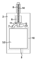
- Die Erfindung wird nachfolgend anhand eines in der Zeichnung dargestellten Ausführungsbeispiels näher erläutert. Es zeigen:
- Figur 1
- Einzelteile eines erfindungsgemäßen Mehrkomponentenbehältnis in Ansicht;
- Figur 2
- die aufeinander angeordneten Einzelteile des Mehrkomponentenbehältnis aus
Figur 1 in Seitenansicht; - Figur 3
- das Mehrkomponentenbehältnis aus
Figuren 1 und2 in geschlossenem Zustand; und - Figur 4
- das Mehrkomponentenbehältnis aus
Figuren 1 und2 in offenem Zustand. - Das in
Figur 1 in Einzelteilen gezeichnete, erfindungsgemäße Mehrkomponentenbehältnis 1 dient zum getrennten Aufbewahren und gemeinsamen Ausdrücken fließfähiger Komponenten. Das gezeichnete Ausführungsbeispiel ist für zwei Komponenten, nämlich einen Binder und einen Härter eines Zweikomponenten-Kunstharzmörtels vorgesehen, d. h. es ist ein Zweikomponentenbehältnis. Das Mehrkomponentenbehältnis 1 ist wie eine Tube ausgebildet, allerdings mit mehreren - im Ausführungsbeispiel zwei - getrennten, noch zu erläuternden Kammern zum getrennten Aufbewahren der Komponenten. Durch Zusammendrücken der Kammern des Mehrkomponentenbehältnis 1 von Hand werden die Komponenten aus dem Mehrkomponentenbehältnis 1 ausgedrückt. Anstatt das Mehrkomponentenbehältnis 1 zusammenzudrücken, kann es auch beginnend an einem, einem Auslass fernen Ende aufgerollt werden, um die Komponenten aus den Kammern auszudrücken. - Das Mehrkomponentenbehältnis 1 weist zwei Wandungen 2 mit muldenförmigen Ausbauchungen 3 und Rillen und eine Trennwand 4 auf, die wie in
Figur 2 zu stehen, aufeinander angeordnet und verschweißt werden. Des Weiteren weist das Mehrkomponentenbehältnis 1 einen Statikmischer 14 auf, der inFigur 2 nicht gezeichnet ist. Die Wandungen 2 sind thermogeformte Kunststofffolien und die Trennwand 4 ist eine ebene Kunststofffolie. Die muldenförmigen Ausbauchungen 3 bilden die Kammern 5 des Mehrkomponentenbehältnis 1 zum getrennten Aufbewahren der Komponenten. Die Kammern 5 werden mit der Trennwand 4 geschlossen, die die Kammern 5 vollständig abdeckt und die Kammern 5 umschließend mit den Wandungen 3 verschweißt wird. Es können auch für jede Wandung 3 eigene Trennwände 4 vorgesehen sein (nicht dargestellt), um die Kammern 5 einzeln zu verschließen und zu befüllen und anschließend die bereits mit den Trennwänden 4 verschweißten Wandungen 3 zum Mehrkomponentenbehältnis 1 zu verschweißen. - In einer Längsmitte weisen die Wandungen 2 mit Abstand von den die Kammern 5 bildenden Ausbauchungen 3 halbzylindrische Ausbauchungen auf, die eine Sammelstelle 6 bilden, die durch ebenfalls thermogeformte Rillen als Kammerauslässe 7 mit den die Kammern 5 bildenden Ausbauchungen 3 kommunizieren. Im Bereich der Sammelstelle 6 ist die Trennwand 4 ausgespart, so dass die aus den Kammern 5 durch die gegenüberliegenden Kammerauslässe 7 ausgedrückten Komponenten in der Sammelstelle 6 zusammenfließen. Von der Sammelstelle 6 führen Rillen als Behältnisauslass 8 in der Längsmitte der Wandungen 2 nach außen. Der Behältnisauslass 8 ist als gerade, halbrohrförmige Rille in den Wandungen 2 geformt, so dass sich durch die Anordnung der Wandungen 2 aufeinander ein gerader, rohrförmiger Behältnisauslass 8 ergibt. Im Bereich des Behältnisauslass 8 ist die Trennwand 4 ebenfalls ausgespart bzw. nicht vorhanden.
- Der Sammelstelle 6 und dem Behältnisauslass 8 gegenüber führen Füllöffnungen 9 in die Kammern 5. Die Füllöffnungen 9 sind ebenfalls als halbzylindrische Rillen in den Wandungen 2 geformt. Die Füllöffnungen 9 sind ebenso wie die Kammerauslässe 7 zu einer Seite versetzt angeordnet, so dass sie am Mehrkomponentenbehältnis 1 zueinander versetzt sind.
- Im Ausführungsbeispiel sind die Wandungen 2 gleiche Teile, die zum Verschweißen zu der das Mehrkomponentenbehältnis 1 bildenden Tube unter Zwischenlage der Trennwand 4 aufeinander gelegt werden, wie es in
Figur 2 zu sehen ist. Beim Aufeinanderlegen sind Hohlseiten der Ausbauchungen 3, Sammelstelle 6, Kammerauslässe 7, Behältnisauslass 8 und Füllöffnungen 9 einander bzw. der Trennwand 4 zugewandt. Die beiden Wandungen 2 sind wie bereits gesagt als gleiche Teile hergestellt, d. h. an den Wandungen 2 sind die Füllöffnungen 9 und die Kammerauslässe 7 zur gleichen Seite versetzt. Zum Verschweißen werden wie gesagt die Hohlseiten der Kammern 5 usw. einander zugewandt, d. h. eine der Wandungen 2 wird umgedreht, wodurch am Mehrkomponentenbehältnis 1 die Füllöffnungen 9 und die Kammerauslässe 7 zu entgegengesetzten Seiten versetzt sind. InFigur 1 ist links eine erhabene Seite der einen Wandung 2 und rechts die Hohlseite der anderen Wandung 2 gezeigt. -
Figuren 3 und 4 zeigen die Hohlseite einer der beiden Wandungen 2 mit dem eingelegten Statikmischer 14. Mit Strichlinien gezeichnet sind Schweißnähte 10 zum Verschweißen der Wandungen 2 und der Trennwand 4 zum Mehrkomponentenbehältnis 1. Die Kammern 5, die Sammelstelle 6 und der Behältnisauslass 8 befinden sich deckungsgleich aufeinander. Der Statikmischer 14 ist stabförmig und im Behältnisausslass 8 veschiebbar. Er weist schrauben- und/oder lamellenförmige Elemente auf, die die aus den Kammern 5 ausgedrückten Komponenten beim Durchströmen mehrfach teilen und wieder zusammenführen und auf diese Weise mischen. Solche Statikmischer 14 sind bekannt und werden hier nicht weiter erläutert. - Der Statikmischer 14 weist an einem Ende einen kreisscheibenförmigen Absperrkörper 11 mit einem zylindrischen Ansatz 12 auf, der sich in der Sammelstelle 6 befindet, wobei der zylindrische Ansatz 12 des Absperrkörpers 11 in einen zylindrischen Fortsatz 13 der Sammelstelle 6 zwischen den Kammerauslässen 7 ragt, die von entgegengesetzten Seiten in den Fortsatz 13 der Sammelstelle 6 münden. Der Absperrkörper 11 mit seinem zylindrischer Ansatz 12 wirken vergleichbar einem Absperrkörper eines Ventils und bilden zusammen mit der Sammelstelle 6 und deren Fortsatz 13 eine Art Ventil: In geschlossener Stellung, den
Figur 3 zeigt, befindet sind der Absperrkörper 11 an einem den Kammern 5 nahen Ende der Sammelstelle 6 und der zylindrische Ansatz 12 ragt in den Fortsatz 13 der Sammelstelle 6. In dieser Stellung verschließt der Absperrkörper 11 die Kammerauslässe 7, so dass die Kammern 5 voneinander getrennt und luftdicht verschlossen sind. Zum Öffnen wird wie inFigur 4 gezeigt der Statikmischer 14 ein Stück weit aus dem Behältnisauslass 8 herausgezogen, wodurch sich der Absperrkörper 11 von dem den Kammern 5 nahen Ende der Sammelstelle 6 entfernt und der der zylindrische Ansatz 12 aus dem Fortsatz 13 der Sammelstelle 6 heraustritt. Die Kammerauslässe 7 sind jetzt zur Sammelstelle 6 offen, so dass die Komponenten aus den Kammern 5 ausgedrückt werden können und durch die Kammerauslässe 7 in die Sammelstelle 6 zusammenfließen. Durch einen hohlen Absperrkörper 11 und/oder durch Löcher im Absperrkörper 11 strömen die Komponenten durch den Absperrkörper 11 oder am Absperrkörper 11 vorbei in den Statikmischer 14, wo sie gemischt werden und an einem den Kammern 5 fernen Ende aus dem Statikmischer 14 und dem Behältnisauslass 8 austreten. Die deckungsgleich aufeinander angeordneten Kammern 5 werden wie bei einer Tube durch Zusammendrücken von Hand gemeinsam ausgedrückt. Wie gesagt kann zum Ausdrücken auch das Mehrkomponentenbehältnis 1 an dem dem Behältnisauslass 8 fernen Ende beginnend aufgerollt werden. - Die Wandungen 2 und die Trennwand 4 können auch anders als durch Schweißen, beispielsweise durch Kleben, verbunden werden. Die Füllöffnungen 9 bleiben bei Verschweißen der Wandungen 2 und der Trennwand 4 offen, so dass die Kammern 5 mit den Komponenten befüllt werden können. Nach dem Befüllen werden die Füllöffnungen 9 luftdicht verschlossen, beispielsweise verschweißt oder zugeklebt. Es ist auch eine Herstellung des Mehrkomponentenbehältnis 1 aus Metallfolien oder einer Mischung aus Metall- und Kunststofffolien möglich. Die Wandungen 2 sind in diesem Fall tiefgezogen. Die Füllöffnungen 9 können in diesem Fall auch durch einen Wickelfalz an dem kammerseitigen Ende des Mehrkomponentenbehältnis 1 verschlossen werden.
- Anstatt aus Einzelteilen können die Wandungen 2 und die Trennwand 4 oder Trennwände 4 auch aus einer Folie bestehen, die so gefaltet wird, dass die Wandungen 2 mit ihren Hohlseiten einander zugewandt aufeinander gelangen und die Trennwand 4 oder Trennwände 4 zwischen die Wandungen 2 gelangt (nicht dargestellt).
-
- 1
- Mehrkomponentenbehältnis
- 2
- Wandung
- 3
- Ausbauchung
- 4
- Trennwand
- 5
- Kammer
- 6
- Sammelstelle
- 7
- Kammerauslass
- 8
- Behältnisauslass
- 9
- Füllöffnung
- 10
- Schweißnaht
- 11
- Absperrkörper
- 12
- Ansatz
- 13
- Fortsatz
- 14
- Statikmischer
Claims (12)
- Von Hand ausdrückbares Mehrkomponentenbehältnis (1) zum getrennten Aufbewahren und durch Zusammendrücken des Mehrkomponentenbehältnis (1) von Hand gemeinsam ausdrückbaren, fließfähigen Komponenten, das für jede Komponente eine zusammendrückbare Kammer (5) aufweist, wobei jede Kammer einen Kammerauslass (7) aufweist, die zu einer Sammelstelle (6) führen, wo die Komponenten beim Ausdrücken der Kammern (5) zusammenfließen, dadurch gekennzeichnet, dass das Mehrkomponentenbehältnis (1) einen Absperrkörper (15) aufweist, der aus einer geschlossenen Stellung, in der er die Kammerauslässe (7) von der Sammelstelle (6) trennt, in eine offene Stellung, in der die Kammerauslässe (7) mit der Sammelstelle (6) kommunizieren, bewegbar ist.
- Mehrkomponentenbehältnis nach Anspruch 1, dadurch gekennzeichnet, dass der Absperrkörper (15) in der Sammelstelle (5) angeordnet ist.
- Mehrkomponentenbehältnis nach Anspruch 1 oder 2, dadurch gekennzeichnet, dass das Mehrkomponentenbehältnis (1) einen Behältnisauslass (8) aufweist, der mit der Sammelstelle (6) kommuniziert, dass das Mehrkomponentenbehältnis (1) einen Statikmischer (14) aufweist, der im Behältnisauslass (8) bewegbar, insbesondere verschiebbar, ist, und dass der Statikmischer (14) den Absperrkörper (15) aufweist, der durch eine Bewegung, insbesondere Verschieben, des Statikmischers (14) aus der geschlossenen in die offene Stellung bewegbar ist.
- Mehrkomponentenbehältnis nach einem der Ansprüche 1 - 3, dadurch gekennzeichnet, dass die Kammern (5) aufeinander angeordnet sind.
- Mehrkomponentenbehältnis nach einem der Ansprüche 1 - 4, dadurch gekennzeichnet, dass die Kammern (5) Füllöffnungen (9) aufweisen.
- Mehrkomponentenbehältnis nach Anspruch 5, dadurch gekennzeichnet, dass die Füllöffnungen (9) versetzt angeordnet sind.
- Mehrkomponentenbehältnis nach einem der vorhergehenden Ansprüche, dadurch gekennzeichnet, dass das Mehrkomponentenbehältnis (1) aufeinander angeordnete Wandungen (2) mit Ausbauchungen (3) und/oder Rillen zur Bildung der Kammern (5), Kammerauslässe (7), Sammelstelle (6) und ggf. des Behältnisauslass (8) und/oder der Füllöffnungen (9) aufweist.
- Mehrkomponentenbehältnis nach Anspruch 7, dadurch gekennzeichnet, dass das Mehrkompontenbehältnis (1) mindestens eine Trennwand (4) aufweist, die mit den Ausbauchungen (3) der Wandungen (2) die Kammern (5) bildet.
- Mehrkomponentenbehältnis nach Anspruch 7, dadurch gekennzeichnet, dass das Mehrkomponentenbehältnis (1) gleiche Wandungen (2) mit Ausbauchungen (3) und/oder Rillen aufweist.
- Mehrkomponentenbehältnis nach einem der Ansprüche 7 oder 9, dadurch gekennzeichnet, dass die Wandungen (2) Thermoformteile sind.
- Mehrkomponentenbehältnis nach einem der vorhergehenden Ansprüche, dadurch gekennzeichnet, dass das Mehrkomponentenbehältnis (1) zwei Kammern (5) aufweist.
- Mehrkomponentenbehältnis nach einem der vorhergehenden Ansprüche, dadurch gekennzeichnet, dass das Mehrkomponentenbehältnis (1) Komponenten eines Mörtels, insbesondere eines Kunstharzmörtels oder eines Klebers enthält.
Priority Applications (1)
| Application Number | Priority Date | Filing Date | Title |
|---|---|---|---|
| PL16167863T PL3095727T3 (pl) | 2015-05-19 | 2016-05-02 | Wyciskany ręcznie pojemnik wieloczęściowy |
Applications Claiming Priority (2)
| Application Number | Priority Date | Filing Date | Title |
|---|---|---|---|
| DE102015107798 | 2015-05-19 | ||
| DE102015115441.2A DE102015115441A1 (de) | 2015-05-19 | 2015-09-14 | Von Hand ausdrückbares Mehrkomponentenbehältnis |
Publications (2)
| Publication Number | Publication Date |
|---|---|
| EP3095727A1 true EP3095727A1 (de) | 2016-11-23 |
| EP3095727B1 EP3095727B1 (de) | 2018-06-13 |
Family
ID=56014800
Family Applications (1)
| Application Number | Title | Priority Date | Filing Date |
|---|---|---|---|
| EP16167863.6A Not-in-force EP3095727B1 (de) | 2015-05-19 | 2016-05-02 | Von hand ausdrückbares mehrkomponentenbehältnis |
Country Status (2)
| Country | Link |
|---|---|
| EP (1) | EP3095727B1 (de) |
| PL (1) | PL3095727T3 (de) |
Citations (3)
| Publication number | Priority date | Publication date | Assignee | Title |
|---|---|---|---|---|
| US4952068A (en) | 1989-03-21 | 1990-08-28 | Flint Theodore R | Static mixing device and container |
| DE202005001203U1 (de) * | 2005-01-26 | 2006-06-14 | Sulzer Chemtech Ag | Mehrkomponentenfolienbehälter |
| EP2277800A1 (de) * | 2009-07-23 | 2011-01-26 | Sulzer Mixpac AG | Vorrichtung zur Lagerung und Dosierung einer Mehrzahl von Komponenten |
-
2016
- 2016-05-02 EP EP16167863.6A patent/EP3095727B1/de not_active Not-in-force
- 2016-05-02 PL PL16167863T patent/PL3095727T3/pl unknown
Patent Citations (4)
| Publication number | Priority date | Publication date | Assignee | Title |
|---|---|---|---|---|
| US4952068A (en) | 1989-03-21 | 1990-08-28 | Flint Theodore R | Static mixing device and container |
| DE202005001203U1 (de) * | 2005-01-26 | 2006-06-14 | Sulzer Chemtech Ag | Mehrkomponentenfolienbehälter |
| EP1843952B1 (de) | 2005-01-26 | 2013-07-31 | Sulzer Mixpac AG | Mehrkomponentenfolienbehaelter |
| EP2277800A1 (de) * | 2009-07-23 | 2011-01-26 | Sulzer Mixpac AG | Vorrichtung zur Lagerung und Dosierung einer Mehrzahl von Komponenten |
Also Published As
| Publication number | Publication date |
|---|---|
| PL3095727T3 (pl) | 2018-11-30 |
| EP3095727B1 (de) | 2018-06-13 |
Similar Documents
| Publication | Publication Date | Title |
|---|---|---|
| EP1843952B1 (de) | Mehrkomponentenfolienbehaelter | |
| EP2566631B1 (de) | Kartuschensystem mit verbundenen förderkolben | |
| DE102008000841B4 (de) | Kartusche und Kolben mit Enlüftungsvorrichtung | |
| DE1766334A1 (de) | Behaelter | |
| DE10347938B4 (de) | Kopfteil für einen Mehrkammerschlauchbeutel | |
| WO2015150196A1 (de) | Kartusche und verfahren zum herstellen einer kartusche | |
| DE202011005121U1 (de) | Misch- und Applikationskapsel zur Herstellung eines Dentalpräparates | |
| EP2560888A1 (de) | Stehfähige kartusche, austragsvorrichtung für eine solche sowie verfahren zur verwendung der kartusche | |
| EP2868393A1 (de) | Austragsstössel, Austragseinrichtung umfassend den Austragsstössel und Verfahren | |
| DE102016104950A1 (de) | Lagerungs- und Mischsystem für pastenförmige Zementkomponenten und Verfahren dafür | |
| DE102013107955A1 (de) | Ausdrückvorrichtung für eine Mehrkammerkartusche | |
| DE102011007475A1 (de) | Folienkartusche und Verfahren zur Herstellung einer Folienkartusche | |
| EP2241517A1 (de) | Mehrkomponenten-Kartusche | |
| DE2800587C2 (de) | Spritz-Kartusche | |
| EP0263313A1 (de) | Zweikomponenten-Behältnis | |
| DE9100054U1 (de) | Vorratspackung für zweikomponentiges Polyurethanmaterial | |
| DE10207763A1 (de) | Mehrkomponenten-Kartusche | |
| EP3368435B1 (de) | Mehrkammer-folienbeutel und dessen verwendung | |
| DE3208472C2 (de) | ||
| DE102005041962B3 (de) | Kartusche | |
| EP3095727B1 (de) | Von hand ausdrückbares mehrkomponentenbehältnis | |
| DE102016122041A1 (de) | Mehrkomponentenbehältnis | |
| EP3368441B1 (de) | Mehrkammer-folienbeutel und dessen verwendung | |
| DE102015115441A1 (de) | Von Hand ausdrückbares Mehrkomponentenbehältnis | |
| EP3606842B1 (de) | Verpackungssystem für eine mehrkomponentenmasse und seine verwendung |
Legal Events
| Date | Code | Title | Description |
|---|---|---|---|
| PUAI | Public reference made under article 153(3) epc to a published international application that has entered the european phase |
Free format text: ORIGINAL CODE: 0009012 |
|
| AK | Designated contracting states |
Kind code of ref document: A1 Designated state(s): AL AT BE BG CH CY CZ DE DK EE ES FI FR GB GR HR HU IE IS IT LI LT LU LV MC MK MT NL NO PL PT RO RS SE SI SK SM TR |
|
| AX | Request for extension of the european patent |
Extension state: BA ME |
|
| STAA | Information on the status of an ep patent application or granted ep patent |
Free format text: STATUS: REQUEST FOR EXAMINATION WAS MADE |
|
| 17P | Request for examination filed |
Effective date: 20170504 |
|
| RBV | Designated contracting states (corrected) |
Designated state(s): AL AT BE BG CH CY CZ DE DK EE ES FI FR GB GR HR HU IE IS IT LI LT LU LV MC MK MT NL NO PL PT RO RS SE SI SK SM TR |
|
| RIC1 | Information provided on ipc code assigned before grant |
Ipc: B65D 81/32 20060101AFI20171026BHEP |
|
| GRAP | Despatch of communication of intention to grant a patent |
Free format text: ORIGINAL CODE: EPIDOSNIGR1 |
|
| STAA | Information on the status of an ep patent application or granted ep patent |
Free format text: STATUS: GRANT OF PATENT IS INTENDED |
|
| INTG | Intention to grant announced |
Effective date: 20171206 |
|
| GRAS | Grant fee paid |
Free format text: ORIGINAL CODE: EPIDOSNIGR3 |
|
| GRAJ | Information related to disapproval of communication of intention to grant by the applicant or resumption of examination proceedings by the epo deleted |
Free format text: ORIGINAL CODE: EPIDOSDIGR1 |
|
| GRAL | Information related to payment of fee for publishing/printing deleted |
Free format text: ORIGINAL CODE: EPIDOSDIGR3 |
|
| STAA | Information on the status of an ep patent application or granted ep patent |
Free format text: STATUS: REQUEST FOR EXAMINATION WAS MADE |
|
| GRAP | Despatch of communication of intention to grant a patent |
Free format text: ORIGINAL CODE: EPIDOSNIGR1 |
|
| STAA | Information on the status of an ep patent application or granted ep patent |
Free format text: STATUS: GRANT OF PATENT IS INTENDED |
|
| GRAA | (expected) grant |
Free format text: ORIGINAL CODE: 0009210 |
|
| STAA | Information on the status of an ep patent application or granted ep patent |
Free format text: STATUS: THE PATENT HAS BEEN GRANTED |
|
| INTC | Intention to grant announced (deleted) | ||
| INTG | Intention to grant announced |
Effective date: 20180504 |
|
| AK | Designated contracting states |
Kind code of ref document: B1 Designated state(s): AL AT BE BG CH CY CZ DE DK EE ES FI FR GB GR HR HU IE IS IT LI LT LU LV MC MK MT NL NO PL PT RO RS SE SI SK SM TR |
|
| REG | Reference to a national code |
Ref country code: GB Ref legal event code: FG4D Free format text: NOT ENGLISH |
|
| REG | Reference to a national code |
Ref country code: CH Ref legal event code: EP Ref country code: AT Ref legal event code: REF Ref document number: 1008265 Country of ref document: AT Kind code of ref document: T Effective date: 20180615 |
|
| REG | Reference to a national code |
Ref country code: IE Ref legal event code: FG4D Free format text: LANGUAGE OF EP DOCUMENT: GERMAN |
|
| REG | Reference to a national code |
Ref country code: DE Ref legal event code: R096 Ref document number: 502016001231 Country of ref document: DE |
|
| REG | Reference to a national code |
Ref country code: NL Ref legal event code: FP |
|
| REG | Reference to a national code |
Ref country code: ES Ref legal event code: FG2A Ref document number: 2684425 Country of ref document: ES Kind code of ref document: T3 Effective date: 20181002 |
|
| REG | Reference to a national code |
Ref country code: LT Ref legal event code: MG4D |
|
| PG25 | Lapsed in a contracting state [announced via postgrant information from national office to epo] |
Ref country code: SE Free format text: LAPSE BECAUSE OF FAILURE TO SUBMIT A TRANSLATION OF THE DESCRIPTION OR TO PAY THE FEE WITHIN THE PRESCRIBED TIME-LIMIT Effective date: 20180613 Ref country code: CY Free format text: LAPSE BECAUSE OF FAILURE TO SUBMIT A TRANSLATION OF THE DESCRIPTION OR TO PAY THE FEE WITHIN THE PRESCRIBED TIME-LIMIT Effective date: 20180613 Ref country code: NO Free format text: LAPSE BECAUSE OF FAILURE TO SUBMIT A TRANSLATION OF THE DESCRIPTION OR TO PAY THE FEE WITHIN THE PRESCRIBED TIME-LIMIT Effective date: 20180913 Ref country code: BG Free format text: LAPSE BECAUSE OF FAILURE TO SUBMIT A TRANSLATION OF THE DESCRIPTION OR TO PAY THE FEE WITHIN THE PRESCRIBED TIME-LIMIT Effective date: 20180913 Ref country code: FI Free format text: LAPSE BECAUSE OF FAILURE TO SUBMIT A TRANSLATION OF THE DESCRIPTION OR TO PAY THE FEE WITHIN THE PRESCRIBED TIME-LIMIT Effective date: 20180613 Ref country code: LT Free format text: LAPSE BECAUSE OF FAILURE TO SUBMIT A TRANSLATION OF THE DESCRIPTION OR TO PAY THE FEE WITHIN THE PRESCRIBED TIME-LIMIT Effective date: 20180613 |
|
| PG25 | Lapsed in a contracting state [announced via postgrant information from national office to epo] |
Ref country code: HR Free format text: LAPSE BECAUSE OF FAILURE TO SUBMIT A TRANSLATION OF THE DESCRIPTION OR TO PAY THE FEE WITHIN THE PRESCRIBED TIME-LIMIT Effective date: 20180613 Ref country code: GR Free format text: LAPSE BECAUSE OF FAILURE TO SUBMIT A TRANSLATION OF THE DESCRIPTION OR TO PAY THE FEE WITHIN THE PRESCRIBED TIME-LIMIT Effective date: 20180914 Ref country code: LV Free format text: LAPSE BECAUSE OF FAILURE TO SUBMIT A TRANSLATION OF THE DESCRIPTION OR TO PAY THE FEE WITHIN THE PRESCRIBED TIME-LIMIT Effective date: 20180613 Ref country code: RS Free format text: LAPSE BECAUSE OF FAILURE TO SUBMIT A TRANSLATION OF THE DESCRIPTION OR TO PAY THE FEE WITHIN THE PRESCRIBED TIME-LIMIT Effective date: 20180613 |
|
| PG25 | Lapsed in a contracting state [announced via postgrant information from national office to epo] |
Ref country code: IS Free format text: LAPSE BECAUSE OF FAILURE TO SUBMIT A TRANSLATION OF THE DESCRIPTION OR TO PAY THE FEE WITHIN THE PRESCRIBED TIME-LIMIT Effective date: 20181013 Ref country code: EE Free format text: LAPSE BECAUSE OF FAILURE TO SUBMIT A TRANSLATION OF THE DESCRIPTION OR TO PAY THE FEE WITHIN THE PRESCRIBED TIME-LIMIT Effective date: 20180613 Ref country code: RO Free format text: LAPSE BECAUSE OF FAILURE TO SUBMIT A TRANSLATION OF THE DESCRIPTION OR TO PAY THE FEE WITHIN THE PRESCRIBED TIME-LIMIT Effective date: 20180613 Ref country code: SK Free format text: LAPSE BECAUSE OF FAILURE TO SUBMIT A TRANSLATION OF THE DESCRIPTION OR TO PAY THE FEE WITHIN THE PRESCRIBED TIME-LIMIT Effective date: 20180613 |
|
| PG25 | Lapsed in a contracting state [announced via postgrant information from national office to epo] |
Ref country code: SM Free format text: LAPSE BECAUSE OF FAILURE TO SUBMIT A TRANSLATION OF THE DESCRIPTION OR TO PAY THE FEE WITHIN THE PRESCRIBED TIME-LIMIT Effective date: 20180613 |
|
| REG | Reference to a national code |
Ref country code: DE Ref legal event code: R097 Ref document number: 502016001231 Country of ref document: DE |
|
| PLBE | No opposition filed within time limit |
Free format text: ORIGINAL CODE: 0009261 |
|
| STAA | Information on the status of an ep patent application or granted ep patent |
Free format text: STATUS: NO OPPOSITION FILED WITHIN TIME LIMIT |
|
| 26N | No opposition filed |
Effective date: 20190314 |
|
| PG25 | Lapsed in a contracting state [announced via postgrant information from national office to epo] |
Ref country code: SI Free format text: LAPSE BECAUSE OF FAILURE TO SUBMIT A TRANSLATION OF THE DESCRIPTION OR TO PAY THE FEE WITHIN THE PRESCRIBED TIME-LIMIT Effective date: 20180613 Ref country code: DK Free format text: LAPSE BECAUSE OF FAILURE TO SUBMIT A TRANSLATION OF THE DESCRIPTION OR TO PAY THE FEE WITHIN THE PRESCRIBED TIME-LIMIT Effective date: 20180613 |
|
| PG25 | Lapsed in a contracting state [announced via postgrant information from national office to epo] |
Ref country code: AL Free format text: LAPSE BECAUSE OF FAILURE TO SUBMIT A TRANSLATION OF THE DESCRIPTION OR TO PAY THE FEE WITHIN THE PRESCRIBED TIME-LIMIT Effective date: 20180613 |
|
| REG | Reference to a national code |
Ref country code: CH Ref legal event code: PL |
|
| PG25 | Lapsed in a contracting state [announced via postgrant information from national office to epo] |
Ref country code: MC Free format text: LAPSE BECAUSE OF FAILURE TO SUBMIT A TRANSLATION OF THE DESCRIPTION OR TO PAY THE FEE WITHIN THE PRESCRIBED TIME-LIMIT Effective date: 20180613 Ref country code: CH Free format text: LAPSE BECAUSE OF NON-PAYMENT OF DUE FEES Effective date: 20190531 Ref country code: LI Free format text: LAPSE BECAUSE OF NON-PAYMENT OF DUE FEES Effective date: 20190531 |
|
| REG | Reference to a national code |
Ref country code: BE Ref legal event code: MM Effective date: 20190531 |
|
| PG25 | Lapsed in a contracting state [announced via postgrant information from national office to epo] |
Ref country code: LU Free format text: LAPSE BECAUSE OF NON-PAYMENT OF DUE FEES Effective date: 20190502 |
|
| PG25 | Lapsed in a contracting state [announced via postgrant information from national office to epo] |
Ref country code: TR Free format text: LAPSE BECAUSE OF FAILURE TO SUBMIT A TRANSLATION OF THE DESCRIPTION OR TO PAY THE FEE WITHIN THE PRESCRIBED TIME-LIMIT Effective date: 20180613 |
|
| PG25 | Lapsed in a contracting state [announced via postgrant information from national office to epo] |
Ref country code: IE Free format text: LAPSE BECAUSE OF NON-PAYMENT OF DUE FEES Effective date: 20190502 |
|
| PG25 | Lapsed in a contracting state [announced via postgrant information from national office to epo] |
Ref country code: BE Free format text: LAPSE BECAUSE OF NON-PAYMENT OF DUE FEES Effective date: 20190531 |
|
| PG25 | Lapsed in a contracting state [announced via postgrant information from national office to epo] |
Ref country code: PT Free format text: LAPSE BECAUSE OF FAILURE TO SUBMIT A TRANSLATION OF THE DESCRIPTION OR TO PAY THE FEE WITHIN THE PRESCRIBED TIME-LIMIT Effective date: 20181015 |
|
| PGFP | Annual fee paid to national office [announced via postgrant information from national office to epo] |
Ref country code: CZ Payment date: 20200429 Year of fee payment: 5 Ref country code: FR Payment date: 20200522 Year of fee payment: 5 Ref country code: NL Payment date: 20200527 Year of fee payment: 5 |
|
| PGFP | Annual fee paid to national office [announced via postgrant information from national office to epo] |
Ref country code: PL Payment date: 20200423 Year of fee payment: 5 Ref country code: IT Payment date: 20200528 Year of fee payment: 5 |
|
| GBPC | Gb: european patent ceased through non-payment of renewal fee |
Effective date: 20200502 |
|
| PG25 | Lapsed in a contracting state [announced via postgrant information from national office to epo] |
Ref country code: GB Free format text: LAPSE BECAUSE OF NON-PAYMENT OF DUE FEES Effective date: 20200502 |
|
| PG25 | Lapsed in a contracting state [announced via postgrant information from national office to epo] |
Ref country code: MT Free format text: LAPSE BECAUSE OF FAILURE TO SUBMIT A TRANSLATION OF THE DESCRIPTION OR TO PAY THE FEE WITHIN THE PRESCRIBED TIME-LIMIT Effective date: 20180613 Ref country code: HU Free format text: LAPSE BECAUSE OF FAILURE TO SUBMIT A TRANSLATION OF THE DESCRIPTION OR TO PAY THE FEE WITHIN THE PRESCRIBED TIME-LIMIT; INVALID AB INITIO Effective date: 20160502 |
|
| PGFP | Annual fee paid to national office [announced via postgrant information from national office to epo] |
Ref country code: ES Payment date: 20210721 Year of fee payment: 6 |
|
| REG | Reference to a national code |
Ref country code: NL Ref legal event code: MM Effective date: 20210601 |
|
| PG25 | Lapsed in a contracting state [announced via postgrant information from national office to epo] |
Ref country code: CZ Free format text: LAPSE BECAUSE OF NON-PAYMENT OF DUE FEES Effective date: 20210502 |
|
| PG25 | Lapsed in a contracting state [announced via postgrant information from national office to epo] |
Ref country code: NL Free format text: LAPSE BECAUSE OF NON-PAYMENT OF DUE FEES Effective date: 20210601 Ref country code: FR Free format text: LAPSE BECAUSE OF NON-PAYMENT OF DUE FEES Effective date: 20210531 |
|
| PG25 | Lapsed in a contracting state [announced via postgrant information from national office to epo] |
Ref country code: MK Free format text: LAPSE BECAUSE OF FAILURE TO SUBMIT A TRANSLATION OF THE DESCRIPTION OR TO PAY THE FEE WITHIN THE PRESCRIBED TIME-LIMIT Effective date: 20180613 |
|
| REG | Reference to a national code |
Ref country code: AT Ref legal event code: MM01 Ref document number: 1008265 Country of ref document: AT Kind code of ref document: T Effective date: 20210502 |
|
| PGFP | Annual fee paid to national office [announced via postgrant information from national office to epo] |
Ref country code: DE Payment date: 20220421 Year of fee payment: 7 |
|
| PG25 | Lapsed in a contracting state [announced via postgrant information from national office to epo] |
Ref country code: AT Free format text: LAPSE BECAUSE OF NON-PAYMENT OF DUE FEES Effective date: 20210502 |
|
| PG25 | Lapsed in a contracting state [announced via postgrant information from national office to epo] |
Ref country code: PL Free format text: LAPSE BECAUSE OF NON-PAYMENT OF DUE FEES Effective date: 20210502 |
|
| PG25 | Lapsed in a contracting state [announced via postgrant information from national office to epo] |
Ref country code: IT Free format text: LAPSE BECAUSE OF NON-PAYMENT OF DUE FEES Effective date: 20200502 |
|
| REG | Reference to a national code |
Ref country code: ES Ref legal event code: FD2A Effective date: 20230626 |
|
| PG25 | Lapsed in a contracting state [announced via postgrant information from national office to epo] |
Ref country code: ES Free format text: LAPSE BECAUSE OF NON-PAYMENT OF DUE FEES Effective date: 20220503 |
|
| REG | Reference to a national code |
Ref country code: DE Ref legal event code: R119 Ref document number: 502016001231 Country of ref document: DE |
|
| PG25 | Lapsed in a contracting state [announced via postgrant information from national office to epo] |
Ref country code: DE Free format text: LAPSE BECAUSE OF NON-PAYMENT OF DUE FEES Effective date: 20231201 |
|
| PG25 | Lapsed in a contracting state [announced via postgrant information from national office to epo] |
Ref country code: IT Free format text: LAPSE BECAUSE OF NON-PAYMENT OF DUE FEES Effective date: 20210502 |