EP3095005B1 - Abnehmbare kopfmontierte anzeigevorrichtung und verfahren zur steuerung davon - Google Patents
Abnehmbare kopfmontierte anzeigevorrichtung und verfahren zur steuerung davon Download PDFInfo
- Publication number
- EP3095005B1 EP3095005B1 EP14878991.0A EP14878991A EP3095005B1 EP 3095005 B1 EP3095005 B1 EP 3095005B1 EP 14878991 A EP14878991 A EP 14878991A EP 3095005 B1 EP3095005 B1 EP 3095005B1
- Authority
- EP
- European Patent Office
- Prior art keywords
- hmd device
- glasses
- eye
- input signal
- look
- Prior art date
- Legal status (The legal status is an assumption and is not a legal conclusion. Google has not performed a legal analysis and makes no representation as to the accuracy of the status listed.)
- Active
Links
Images








Classifications
-
- G—PHYSICS
- G02—OPTICS
- G02B—OPTICAL ELEMENTS, SYSTEMS OR APPARATUS
- G02B27/00—Optical systems or apparatus not provided for by any of the groups G02B1/00 - G02B26/00, G02B30/00
- G02B27/01—Head-up displays
- G02B27/017—Head mounted
- G02B27/0176—Head mounted characterised by mechanical features
-
- G—PHYSICS
- G02—OPTICS
- G02B—OPTICAL ELEMENTS, SYSTEMS OR APPARATUS
- G02B27/00—Optical systems or apparatus not provided for by any of the groups G02B1/00 - G02B26/00, G02B30/00
- G02B27/01—Head-up displays
- G02B27/017—Head mounted
-
- G—PHYSICS
- G02—OPTICS
- G02B—OPTICAL ELEMENTS, SYSTEMS OR APPARATUS
- G02B27/00—Optical systems or apparatus not provided for by any of the groups G02B1/00 - G02B26/00, G02B30/00
- G02B27/01—Head-up displays
- G02B27/0179—Display position adjusting means not related to the information to be displayed
-
- G—PHYSICS
- G06—COMPUTING OR CALCULATING; COUNTING
- G06F—ELECTRIC DIGITAL DATA PROCESSING
- G06F3/00—Input arrangements for transferring data to be processed into a form capable of being handled by the computer; Output arrangements for transferring data from processing unit to output unit, e.g. interface arrangements
- G06F3/01—Input arrangements or combined input and output arrangements for interaction between user and computer
- G06F3/03—Arrangements for converting the position or the displacement of a member into a coded form
- G06F3/033—Pointing devices displaced or positioned by the user, e.g. mice, trackballs, pens or joysticks; Accessories therefor
- G06F3/0354—Pointing devices displaced or positioned by the user, e.g. mice, trackballs, pens or joysticks; Accessories therefor with detection of two-dimensional [2D] relative movements between the device, or an operating part thereof, and a plane or surface, e.g. 2D mice, trackballs, pens or pucks
- G06F3/03547—Touch pads, in which fingers can move on a surface
-
- G—PHYSICS
- G06—COMPUTING OR CALCULATING; COUNTING
- G06F—ELECTRIC DIGITAL DATA PROCESSING
- G06F3/00—Input arrangements for transferring data to be processed into a form capable of being handled by the computer; Output arrangements for transferring data from processing unit to output unit, e.g. interface arrangements
- G06F3/01—Input arrangements or combined input and output arrangements for interaction between user and computer
- G06F3/03—Arrangements for converting the position or the displacement of a member into a coded form
- G06F3/033—Pointing devices displaced or positioned by the user, e.g. mice, trackballs, pens or joysticks; Accessories therefor
- G06F3/038—Control and interface arrangements therefor, e.g. drivers or device-embedded control circuitry
-
- G—PHYSICS
- G06—COMPUTING OR CALCULATING; COUNTING
- G06F—ELECTRIC DIGITAL DATA PROCESSING
- G06F3/00—Input arrangements for transferring data to be processed into a form capable of being handled by the computer; Output arrangements for transferring data from processing unit to output unit, e.g. interface arrangements
- G06F3/01—Input arrangements or combined input and output arrangements for interaction between user and computer
- G06F3/03—Arrangements for converting the position or the displacement of a member into a coded form
- G06F3/041—Digitisers, e.g. for touch screens or touch pads, characterised by the transducing means
- G06F3/0416—Control or interface arrangements specially adapted for digitisers
-
- G—PHYSICS
- G06—COMPUTING OR CALCULATING; COUNTING
- G06F—ELECTRIC DIGITAL DATA PROCESSING
- G06F3/00—Input arrangements for transferring data to be processed into a form capable of being handled by the computer; Output arrangements for transferring data from processing unit to output unit, e.g. interface arrangements
- G06F3/01—Input arrangements or combined input and output arrangements for interaction between user and computer
- G06F3/048—Interaction techniques based on graphical user interfaces [GUI]
- G06F3/0484—Interaction techniques based on graphical user interfaces [GUI] for the control of specific functions or operations, e.g. selecting or manipulating an object, an image or a displayed text element, setting a parameter value or selecting a range
-
- G—PHYSICS
- G06—COMPUTING OR CALCULATING; COUNTING
- G06F—ELECTRIC DIGITAL DATA PROCESSING
- G06F3/00—Input arrangements for transferring data to be processed into a form capable of being handled by the computer; Output arrangements for transferring data from processing unit to output unit, e.g. interface arrangements
- G06F3/01—Input arrangements or combined input and output arrangements for interaction between user and computer
- G06F3/048—Interaction techniques based on graphical user interfaces [GUI]
- G06F3/0487—Interaction techniques based on graphical user interfaces [GUI] using specific features provided by the input device, e.g. functions controlled by the rotation of a mouse with dual sensing arrangements, or of the nature of the input device, e.g. tap gestures based on pressure sensed by a digitiser
- G06F3/0488—Interaction techniques based on graphical user interfaces [GUI] using specific features provided by the input device, e.g. functions controlled by the rotation of a mouse with dual sensing arrangements, or of the nature of the input device, e.g. tap gestures based on pressure sensed by a digitiser using a touch-screen or digitiser, e.g. input of commands through traced gestures
-
- G—PHYSICS
- G02—OPTICS
- G02B—OPTICAL ELEMENTS, SYSTEMS OR APPARATUS
- G02B27/00—Optical systems or apparatus not provided for by any of the groups G02B1/00 - G02B26/00, G02B30/00
- G02B27/01—Head-up displays
- G02B27/0149—Head-up displays characterised by mechanical features
- G02B2027/015—Head-up displays characterised by mechanical features involving arrangement aiming to get less bulky devices
-
- G—PHYSICS
- G02—OPTICS
- G02B—OPTICAL ELEMENTS, SYSTEMS OR APPARATUS
- G02B27/00—Optical systems or apparatus not provided for by any of the groups G02B1/00 - G02B26/00, G02B30/00
- G02B27/01—Head-up displays
- G02B27/0149—Head-up displays characterised by mechanical features
- G02B2027/0154—Head-up displays characterised by mechanical features with movable elements
-
- G—PHYSICS
- G02—OPTICS
- G02B—OPTICAL ELEMENTS, SYSTEMS OR APPARATUS
- G02B27/00—Optical systems or apparatus not provided for by any of the groups G02B1/00 - G02B26/00, G02B30/00
- G02B27/01—Head-up displays
- G02B27/017—Head mounted
- G02B2027/0178—Eyeglass type
-
- G—PHYSICS
- G06—COMPUTING OR CALCULATING; COUNTING
- G06F—ELECTRIC DIGITAL DATA PROCESSING
- G06F2203/00—Indexing scheme relating to G06F3/00 - G06F3/048
- G06F2203/033—Indexing scheme relating to G06F3/033
- G06F2203/0339—Touch strips, e.g. orthogonal touch strips to control cursor movement or scrolling; single touch strip to adjust parameter or to implement a row of soft keys
Definitions
- the present specification relates to a detachable head mounted display device and a method for controlling a display unit, a first sensor unit and a second sensor unit of a detachable head mounted display device.
- a head mounted display (hereinafter, referred to as 'HMD') device allows a user to wear on his/her head like eye-glasses in accordance with its lightweight tendency. Visual information displayed in the HMD device may be provided to the user.
- the HMD device may be different from eye-glasses worn by a user in view of size and shape. Accordingly, if visual information displayed in the HMD device is provided to the user, the user may suffer inconvenience in receiving the visual information due to non-focusing on the visual information which is displayed. Also, if the user wears the HMD device, since the HMD device has a size and a shape different from those of eye-glasses worn by the user, the user may suffer inconvenience in wearing the HMD device.
- the user carries the HMD device, there may be inconvenience in that it is difficult to manufacture the HMD device at a size of eye-glasses, whereby it is difficult for the user to carry the HMD device.
- the HMD device should be manufactured at a micro size to be detachably affixed to eye-glasses of a user and provide visual information considering features of the eye-glasses of the user.
- U.S. Patent Application Publication No. 2010/079356 A1 discloses a head-mounted display system allowing a user to couple and decouple a portable electronic device, such as a handheld portable electronic device, with a separate head-mounted device.
- the portable electronic device may be physically coupled to the head-mounted device such that the portable electronic device can be worn on the user's head, and may be operatively coupled to the head-mounted device such that the portable electronic device and the head mounted device can communicate and operate with one another.
- US 2012/299870 A1 discloses a wearable heads-up display with integrated finger-tracking input sensor.
- US 2013/181888 A1 relates to a head-mount display in which an input operation unit serves to control the image and includes a touch sensor provided to the display portion.
- the present specification is directed to a detachable HMD device and a method for controlling the same, which substantially obviate one or more problems due to limitations and disadvantages of the related art.
- a detachable head mounted display, HMD, device according to independent claim 1.
- a head mounted display (HMD) device of the present specification may mean a wearable device that may be worn by a body of a user to display visual information.
- the HMD device may be a detachable HMD in accordance with the present specification.
- FIG. 1 is a block diagram illustrating an HMD device 100 according to one embodiment of the present specification which is not encompassed by the wording of the claims but considered to be useful for understanding the invention.
- the HMD device 100 may include a display unit 110, a detached sensor unit 120, a sensor unit 130, and a controller 140.
- the display unit 110 may display virtual information.
- the visual information may mean information that may be recognized visually, such as image, text, moving picture, photo, and picture.
- the display unit 110 may display augmented reality information related to real object.
- the display unit 110 may display a stereoscopic image by using a stereoscopic camera. At this time, the display unit 110 may control a position and a distance where visual information is displayed, by considering features of eye-glasses to which the HMD device 100 is affixed and eyesight of a user who wears the eye-glasses.
- the display unit 110 may adjust a position and a distance of the visual information which is displayed, by considering a lens size or thickness of eye-glasses to which the HMD device 100 is affixed, or a distance between eyes of the user who wears the eye-glasses and the HMD device 100.
- the HMD device 100 may control a focus of the displayed visual information in accordance with the eye-glasses to which the HMD device 100 is affixed and the user of the eye-glasses. This will be described with reference to FIG. 10 .
- an optical see-through display panel may be used as the display unit 110.
- the detached sensor unit 120 is configured to detect whether the HMD device 100 has been affixed to the eye-glasses.
- the HMD device 100 may generate an electromagnetic pattern.
- the HMD device 100 may generate various electromagnetic patterns by generating a current and controlling an occurrence period, duration time and strength of the current.
- the HMD device 100 may output an electromagnetic pattern at an affixed portion where the HMD device 100 is affixed to the eye-glasses.
- the affixed portion means a portion where the HMD device 100 may be affixed to the eye-glasses.
- the HMD device 100 may have an eye-glasses frame shaped groove structure so that the HMD device may be affixed to the eye-glasses. If the HMD device 100 is affixed to the eye-glasses, the HMD device 100 may be attached and affixed to the eye-glasses. If the HMD device 100 is affixed to the eye-glasses, the detached sensor unit 120 may sense variation of the electromagnetic pattern output from the affixed portion. In more detail, the eye-glasses to which the HMD device 100 is affixed may be coated with a material having conductivity.
- the material having conductivity may be, but not limited to, a material, such as Cu, Al, Au, or carbon nanotube, which is coated in the eye-glasses to flow a micro current.
- the detached sensor unit 120 may detect that the HMD device 100 has been affixed to the eye-glasses by sensing that the output electromagnetic pattern is varied by the eye-glasses coated with the conductive material.
- the detached sensor unit 120 may detect that the eye-glasses has been affixed to the HMD device 100 by sensing magnetic field varied by the eye-glasses coated with the conductive material.
- the detached sensor unit 120 may detect that the HMD device 100 has been affixed to the eye-glasses by using a radio frequency identification (RFID) signal.
- RFID radio frequency identification
- the eye-glasses to which the HMD device 100 is affixed may include an RFID tag.
- the detached sensor unit 120 may include an RFID reader.
- the detached sensor unit 120 may identify RFID tag information of the eye-glasses to which the HMD device 100 is affixed, by using the RFID reader, and may detect that the HMD device 100 is affixed to the eye-glasses.
- the detached sensor unit 120 may include a bar code reader, and may detect that the HMD device 100 has been affixed to the eye-glasses by using bar code information.
- the detached sensor unit 120 may further include a camera unit, and may detect that the HMD device 100 has been affixed to the eye-glasses by using QR code information.
- the detached sensor unit 120 may refer to a sensor unit that may detect that that the HMD device 100 has been affixed to the eye-glasses and is not limited to the aforementioned example.
- the sensor unit 130 may detect an input signal generated when the eye-glasses to which the HMD device 100 is affixed is touched.
- the HMD device 100 may be manufactured in a micro shape, and may be used to be affixed to the eye-glasses.
- the sensor unit 130 may detect the input signal generated when the eye-glasses to which the HMD device 100 is affixed is touched, and may forward the input signal to the controller 140, whereby the input signal may be used as a control input.
- the HMD device 100 may use the input signal generated when the eye-glasses to which the HMD device 100 is affixed is touched as a control input that controls the displayed user interface.
- the eye-glasses coated with the HMD device 100 may be coated with the conductive material as described above. If the HMD device 100 is affixed to the eye-glasses, the HMD device 100 may apply a micro current to the eye-glasses. At this time, the micro current may flow the portion of the eye-glasses, which is coated with the conductive material. If the HMD device 100 applies the micro current to the eye-glasses, the sensor unit 130 may detect a micro signal varied when the eye-glasses is touched as an input signal. In more detail, if the eye-glasses are touched, the sensor unit 130 may sense that electric conductivity or electromagnetic pattern of the conductive material coated in the eye-glasses is varied, thereby detecting the touched area of the eye-glasses.
- the HMD device 100 may include a first contact point for applying a current and a second contact point for receiving the current applied from the first contact point.
- the HMD device 100 may include a current reception unit. At this time, the current reception unit may receive the current applied from the first contact point.
- the current reception unit may include the second contact point. The current reception unit may control an input signal sensing area where the input signal is detected, by controlling the position of the second contact point. This will be described with reference to FIG. 5 .
- the aforementioned sensors may be included in the HMD device 100 as separate elements, or may be incorporated into at least one element.
- the detached sensor unit 120 and the sensor unit 130 may be an incorporated sensor unit.
- the incorporated sensor unit may detect whether the HMD device 100 has been affixed to the eye-glasses simultaneously with the input signal generated when the eye-glasses are touched.
- the controller 140 may detect that the HMD device 100 has been affixed to the eye-glasses, and may acquire identification information of the affixed eye-glasses.
- the identification information may include feature information on the eye-glasses to which the HMD device 100 is affixed.
- the identification information may include at least one of a type of the eye-glasses, appearance of the eye-glasses, parts of the eye-glasses, a material coated in the eye-glasses, conductivity of the eye-glasses, a length of an area of the eye-glasses coated with a conductive material, a lens size of the eye-glasses, and a thickness of the eye-glasses.
- the identification information may include information on the eye-glasses to which the HMD device 100 is affixed. Also, the identification information may be acquired through at least one of the RFID signal, the bar code, and the QR code. Also, as an example, the HMD device 100 may be affixed to the eye-glasses by using the detached sensor unit 120 and at the same time acquire the identification information.
- the controller 140 acquires a look up table related to the identification information on the basis of the identification information.
- the look up table is a set of predetermined values for a given input signal.
- the controller 140 acquires a control input that performs a function at the user interface which is displayed.
- the controller 140 receives the input signal from the sensor unit 130 and acquires the control input matched with the input signal from the look up table.
- the look up table is a table representing correspondence of the control input corresponding to the input signal.
- the look up table may be set differently depending on the acquired identification information. This will be described later with reference to FIG. 6b .
- the controller 140 acquires a control input related to the input signal from the look up table.
- the controller 140 performs a function of the HMD device 100 in accordance with the control input. At this time, the function may be varied depending on the user interface performed by the HMD device 100. This will be described later with reference to FIGs. 7a to 7c .
- the HMD device 100 may further include a storage unit (not shown).
- the storage unit may store various digital data such as moving pictures, audios, images and applications.
- the controller 140 may further acquire user information of the user of the eye-glasses, and may generate a folder for storing data on the basis of user information.
- the user information may be information included in the aforementioned identification information.
- the user information is separately set by the user of the eye-glasses, and may be information corresponding to the user who uses the eye-glasses.
- the controller 140 may store information, data or security information on the function performed by the user of the eye-glasses in a state that the HMD device 100 is affixed to the eye-glasses.
- various users may use the HMD device 100 in such a manner that the HMD device 100 is affixed to their eye-glasses.
- the controller 140 needs to store the function, data or security information performed by the eye-glasses to which the HMD device 100 is affixed, for each user.
- the HMD device 100 may identify a plurality of users who use the HMD device 100, from one another. As a result, the detachable HMD device 100 may be used by the plurality of users.
- FIG. 2 is a diagram illustrating a non-detachable HMD 210 device according to an unclaimed example.
- the HMD device 210 may be worn by the user like the eye-glasses.
- the HMD device 210 may be manufactured in a shape of eye-glasses or helmet and then may be worn by the user.
- visual information displayed in the HMD device 210 may be provided to the user through the HMD device worn by the user.
- the user who wears the HMD device 210 may view the visual information only displayed in the HMD device 210 by blocking external exposure.
- the HMD device 210 may provide the user with stereoscopic image or augmented reality image.
- the HMD device 210 may be used for console games or 3D car game.
- the user may enjoy visual information by wearing the eye-glasses type or helmet type HMD device 210 and blocking external exposure. If the user moves in a state that the user wears the HMD device 210, a problem occurs in that the user cannot secure a clear view. Also, the user who wears eye-glasses may wear the HMD device 210 by taking off the eye-glasses. However, the HMD device 210 may be manufactured in accordance with a certain standard without being manufactured by reflecting eye-glasses features or eyesight information of the user. At this time, if eye-glasses features of the user and eyesight information of the user are different from those of the HMD device 210, a problem may occur in that the user cannot view visual information clearly even though the user wears the HMD device 210.
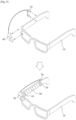
- FIG. 3 is a diagram illustrating a detachable HMD device 100 according to one embodiment of the present specification not encompassed by the wording of the claims but considered to be useful for understanding the invention.
- the HMD device 100 may detachably be affixed to the eye-glasses.
- the HMD device 100 may be manufactured in a micro shape and then affixed to eye-glasses 310 worn by a user.
- the HMD device 100 may be manufactured in a micro shape to be affixed to the eye-glasses 310.
- the HMD device 100 may be manufactured at a small size to be affixed to a part of the eye-glasses 310 of the user.
- the HMD device 100 is worn at a lens or temple part of the eye-glasses 310 to display visual information at a portion where the user's view is located.
- the HMD device may be affixed to, but not limited to, another part of the eye-glasses 310 to provide the user with visual information.
- the HMD device 100 may detect various control inputs of the user in accordance with the position of the eye-glasses 310. If the user forwards the control input to the HMD device 100, since the HMD device 100 is manufacture in a micro shape and affixed to the eye-glasses 310, the control input provided to the HMD device 100 may be limited. Accordingly, the HMD device 100 may provide different control inputs depending on the position where the HMD device 100 is affixed to the eye-glasses 310, thereby detecting various control inputs of the user. Also, as an example, the HMD device 100 may provide various user interfaces in accordance with the position of the eye-glasses 310.
- the HMD device 100 may affixed to a left lens part of the eye-glasses 310 or a right lens part of the eye-glasses 310. If the HMD device 100 is affixed to the right lens part of the eye-glasses 310, the HMD device 100 may provide an interface that plays video viewed by the user. Also, if the HMD device 100 is affixed to the left lens part of the eye-glasses 310, the HMD device 100 may provide an interface that plays music listened by the user. In addition, the HMD device 100 may be affixed to the other parts of the eye-glasses 310 without limitation to the aforementioned examples.
- the HMD device 100 may be manufactured at various sizes.
- the HMD device 100 may be manufactured at various sizes considering a size and a length of the eye-glasses 310 to which the HMD device 100 is affixed.
- the HMD device 100 may be manufactured by standardizing the size and the length of the eye-glasses 310 to which the HMD device 100 is affixed.
- the eye-glasses 310 to which the HMD device 100 is affixed may be coated with a conductive material.
- the conductive material may be, but not limited to, a material, such as Al, Au, or carbon nanotube, which is coated in the eye-glasses 310 to flow a current in the eye-glasses 310.
- the current is a micro current that may detect the input signal corresponding to the input of the user.
- the conductive material may be coated in the entire frame of the eye-glasses 310. Also, the conductive material may be coated in a part of the frame of the eye-glasses 310.
- the HMD device 100 may control an area where the input signal which is touched is detected.
- the HMD device 100 may be manufactured in a micro shape. Accordingly, the HMD device 100 may enlarge the area where the control input of the user is detected, towards the eye-glasses 310 to which the HMD device 100 is affixed. At this time, the HMD device 100 may apply a current, which detects an input signal generated when the eye-glasses 310 to which the HMD device 100 is affixed are touched, to the eye-glasses 310. Also, the HMD device 100 may receive the current applied to the eye-glasses 310. As a result, the HMD device 100 may receive the current varied by the touch input and detect the input signal. In other words, the HMD device 100 may be affixed to the eye-glasses 310 and use the input signal generated when the eye-glasses 310 are touched.
- FIG. 4 is a diagram illustrating a method for enabling an HMD device 100 to detect an input signal generated when eye-glasses 310 are touched in accordance with an unclaimed example.
- the HMD device 100 may be affixed to the eye-glasses 310.
- the HMD device 100 may detect that the HMD device 100 is affixed to the eye-glasses 310, by using the detached sensor unit 120.
- the HMD device 100 may output an electromagnetic pattern to the portion of the eye-glasses to which the HMD device 100 is affixed, and may detect that the HMD device 100 is affixed to the eye-glasses 310 by detecting the electromagnetic pattern varied by the eye-glasses 310 coated with a conductive material.
- the HMD device 100 may detect that the HMD device 100 is affixed to the eye-glasses 310, through an RFID signal, a bar code, or a QR code.
- the HMD device is not limited to the aforementioned embodiment.
- the HMD device 100 may apply a current to the eye-glasses 310 and receive the applied current.
- the HMD device 100 may apply a current to the eye-glasses 310 through a first contact point 410 and receive the current applied to the eye-glasses 310, through a second contact point 420. If the current is applied from the HMD device 100 to the eye-glasses 310, the current may flow to the frame of the eye-glasses 310.
- the HMD device 100 may apply the current to the eye-glasses 310 through the first contact point 410, and may receive the applied current by the second contact point 420 along the frame of the eye-glasses 310.
- the HMD device 100 may regard the first contact point 410 and the second contact point 420 as one contact point.
- the HMD device 100 may generate one contact point at the position where the HMD device 100 is affixed to the eye-glasses 310, and may apply the current to one contact point and receive the current.
- the HMD device 100 may be affixed to the eye-glasses 310 and sense variation of the current at the eye-glasses 310 through the contact point where the current is applied and received, and is not limited to the aforementioned embodiment.
- the current may flow to the area only of the frame of the eye-glasses 310, which is coated with the conductive material.
- the HMD device 100 may detect the input signal generated when the eye-glasses to which the HMD device 100 is affixed are touched by using the sensor unit 130. In more detail, the current may flow to the eye-glasses 310 through the HMD device 100. At this time, the user 430 may touch the eye-glasses to which the HMD device 100 is affixed. If the user 430 touches the eye-glasses 310, the HMD device 100 may detect a point of the frame of the eye-glasses 310, wherein the point is touched by the user 430.
- the current of the point which is touched may be varied by the touch input of the user 430.
- the HMD device 100 may detect the input signal generated when the user 430 touches the eye-glasses 310 by detecting the point where the current is varied. Also, for example, the HMD device 100 may detect the input signal, which is touched twice by the user 430 or touched by a slide. For another example, the HMD device 100 may detect the input signal generated when the user touches a plurality of points of the eye-glasses 310. The HMD device 100 may detect the input signal without limitation to the aforementioned embodiment.
- FIG. 5 is a diagram illustrating a method for enabling an HMD device 100 to further include a current reception unit 510 in accordance with one embodiment of the present specification not encompassed by the wording of the claims but considered to be useful for understanding the invention.
- the HMD device 100 may further include a current reception unit 510.
- the current reception unit 510 may be a separate unit connected with the HMD device 100 through a wire.
- the current reception unit 510 may receive the current applied to the eye-glasses 310 by the HMD device 100.
- the current reception unit 510 may include a second contact point 420 where the current applied to the eye-glasses 310 by the HMD device 100.
- the current reception unit 510 may be affixed to another part of the eye-glasses 310 to which the HMD device 100 is affixed.
- the HMD device 100 may be affixed to a lens part of the eye-glasses 310, that is, the position where the user's view reaches.
- the current reception unit 510 may be affixed to a temple part of the eye-glasses 310 to which the HMD device 100 is affixed, wherein the temple part is connected with the lens of the eye-glasses 310.
- the first contact point 410 that applies the current may be located at the position where the HMD device 100 is affixed, and the second contact point 420 that receives the current applied to the eye-glasses 310 may be located at the current reception unit 510.
- the HMD device 100 may apply the current to the eye-glasses 310 through the first contact point 410, and the current reception unit 100 may receive the current applied to the eye-glasses 310 through the second contact point 420. At this time, the current may only flow between the first contact point 410 where the current is applied and the second contact point 420 that receives the current.
- the HMD device 100 may only flow the current to the position where the HMD device 100 is affixed and the position where the current reception unit 510 is affixed, and may detect the touch input of the user only at the area where the current flows.
- the HMD device 100 may be located at the area of the eye-glasses 310, which is coated with the conductive material.
- the first contact point 410 and the second contact point 420 may be located at the area of the eye-glasses 310, which is coated with the conductive material.
- the HMD device 100 may set the area between the HMD device 100 and the current reception unit 510 as the input signal sensing area 520.
- the input signal sensing area 520 may mean the area of the eye-glasses 310, where the current flows by means of the HMD device.
- the HMD device 100 may detect the touch input only of the user, which corresponds to the input signal sensing area 520.
- the user may set the area of the eye-glasses 310, where an input for controlling the HMD device 100 is input. In other words, if the HMD device 100 is affixed to the eye-glasses, the user may control the HMD device 100 by touching the input signal sensing area 520.
- the HMD device 100 may control the length of the input signal sensing area 520 on the basis of the position where the current reception unit 510 is affixed. Also, as an example, if the HMD device 100 is affixed to the right lens of the eye-glasses 310 and the current reception unit 510 is affixed to the right temple, the input signal sensing area 520 may be formed at the right temple of the eye-glasses 310. Also, if the HMD device 100 is affixed to the left lens and the current reception unit 510 is affixed to the left temple, the input signal sensing area 520 may be formed at the left temple of the eye-glasses 310.
- the HMD device 100 may control the user interface, which is displayed, on the basis of the length or the position of the input signal sensing area 520.
- the HMD device 100 may detect the positions of the first contact point 410 and the second contact point 420. If the HMD device 100 detects the positions of the first contact point 410 and the second contact point 420, the HMD device 100 may detect the length and the position of the input signal sensing area 520. At this time, the HMD device 100 may display another user interface on the basis of at least one of the length and the position of the input signal sensing area 520.
- the HMD device 100 may display the user interface on the basis of the length of the input signal sensing area 520. In more detail, if the length of the input signal sensing area 520 is more than a threshold length, the HMD device 100 may display the user interface that plays video. Also, if the length of the input signal sensing area 520 is less than the threshold length, the HMD device 100 may display the user interface that plays music.
- the HMD device 100 may display the user interface on the basis of the position of the input signal sensing area 520.
- the HMD device 100 may display the user interface that plays stereoscopic image.
- the HMD device 100 may display the user interface that displays augmented reality.
- the HMD device 100 may provide the user interface by considering the position and the length of the input signal sensing area 520. Also, the user interface may be set by the user or the HMD device 100, and is not limited to the aforementioned embodiment.
- the HMD device 100 may control the look up table on the basis of the length or the position of the input signal sensing area 520. This will be described later with reference to FIGs. 7a to 7c and FIGs. 8a and 8b .
- FIGs. 6a and 6b are diagrams illustrating a method for enabling an HMD device 100 to acquire identification information and acquire a look up table in accordance with one embodiment of the present specification not encompassed by the wording of the claims but considered to be useful for understanding the invention.
- the HMD device 100 may acquire identification information 640 of the eye-glasses 310 to which the HMD device 100 is affixed.
- the identification information 640 may mean information identified per eye-glasses 310 to which the HMD device 100 is affixed.
- the identification information may include at least one of a type of the eye-glasses, appearance of the eye-glasses, parts of the eye-glasses, a material coated in the eye-glasses, conductivity of the eye-glasses, a length of an area of the eye-glasses coated with a conductive material, a lens size of the eye-glasses, and a thickness of the eye-glasses.
- the identification information may include information on the eye-glasses to which the HMD device 100 is affixed, and is not limited to the aforementioned examples.
- the HMD device 100 may acquire the identification information 640 by using at least one of variation of electric signal, RFID signal, bar code, and QR code. Also, the HMD device 100 may acquire the identification information through a value predetermined between the eye-glasses 310 and the HMD device 100. The HMD device 100 may acquire the identification information without limitation to the aforementioned embodiment.
- the HMD device 100 may acquire a look up table 650 related to the identification information 640. If the HMD device 100 acquires the look up table 650, the HMD device 100 may receive the input signal, which is generated when the eye-glasses 310 to which the HMD device 100 is affixed are touched, from the sensor unit 130.
- the look up table 650 may be a set of predetermined values corresponding to a given input signal.
- the look up table 650 may be a value corresponding to a control input matched with the input signal which is generated when the user 430 touches the eye-glasses 310.
- the look up table 650 may be set on the basis of the acquired identification information 640.
- the look up table 650 may be set differently depending on the conductive material coated in the eye-glasses 310 and the length of the eye-glasses coated with the conductive material among the identification information 640.
- the HMD device 100 may acquire the control input related to the input signal from the look up table 650.
- the control input may be a control input for an interface performed by the HMD device 100.
- the HMD device 100 may acquire the control input, which performs one-click, from the look up table 650.
- the HMD device 100 may acquire the control input, which performs a slide, from the look up table 650.
- the HMD device 100 may acquire a control input corresponding to multi-touch from the look up table 650.
- the look up table 650 may be set to include the control input corresponding to the aforementioned embodiments.
- the look up table 650 may be varied by the user or the HMD device 100 without limitation to the aforementioned embodiment.
- the HMD device 100 may perform a function corresponding to the control input.
- the function may be a command that controls the user interface performed by the HMD device 100.
- the HMD device 100 may perform a function that stops the music which is being played, or replays the music.
- the HMD device 100 displays a menu and acquires the control input, which performs one-click, from the look up table 650, the HMD device 100 may perform a function that selects an icon in a menu.
- the HMD device 100 may control the function performed by the control input by considering the user interface which is performed.
- FIG. 6a is a diagram illustrating a method for enabling an HMD device 100 to acquire identification information 640. If the HMD device 100 detects that the HMD device 100 is affixed to the eye-glasses 310, the HMD device 100 may acquire the identification information 640. At this time, the HMD device 100 may detect RFID signal 610 of the eye-glasses 310 to which the HMD device 100 is affixed. In more detail, the eye-glasses 310 may include RFID tag in which the identification information on the eye-glasses is written. At this time, the HMD device 100 may further include an RFID reader. The HMD device 100 may acquire the identification information 640 on the eye-glasses 310 by using the RFID reader.
- the HMD device 100 may detect a bar code 620 of the eye-glasses 310 to which the HMD device 100 is affixed.
- the eye-glasses 310 may include a bar code in which the identification information 640 on the eye-glasses is written.
- the HMD device 100 may further include a bar code reader. The HMD device 100 may detect the bar code 620 included in the eye-glasses 310 by using the bar code reader, and may acquire the identification information 640 on the eye-glasses 310 to which the HMD device 100 is affixed.
- the HMD device 100 may detect QR code 630 of the eye-glasses 310 to which the HMD device 100 is affixed.
- the eye-glasses 310 may include QR code in which the identification information 640 on the eye-glasses is written.
- the HMD device 100 may further include a camera unit (not shown). The HMD device 100 may detect QR code 630 by using the camera unit and acquire the identification information 640 on the eye-glasses 310 to which the HMD device is affixed.
- the HMD device 100 may generate an electric signal and detect the eye-glasses 310 through variation of the electric signal.
- the HMD device may detect the eye-glasses without limitation to the aforementioned embodiments.
- the HMD device 100 may acquire the look up table 650 on the basis of the identification information 310. If the HMD device 100 acquires the look up table 650, the HMD device 100 may determine the look up table by reflecting information included in the identification information 640. For example, the HMD device 100 may acquire identification information 640 on first eye-glasses. The first eye-glasses may be coated with aluminum, wherein the entire frame of the eye-glasses 310 may be coated with a conductive material. Also, the HMD device 100 may acquire identification information 640 on second eye-glasses.
- the second eye-glasses may be coated with carbon nanotube, wherein a right temple area of the eye-glasses 310 may only be coated with a conductive material.
- the HMD device 100 may set the look up table 650 differently for each of the case where the first eye-glasses are identified and the case where the second eye-glasses are identified.
- the look up table 650 may be a table, which corresponds to the input signal generated when the eye-glasses 310, to which the HMD device is affixed are touched, and a control input corresponding to the input signal.
- the look up table 650 may be set differently per eye-glasses on the basis of the identification information 640.
- the identification information 640 is not limited to the aforementioned embodiment, and may be information representing features of the eye-glasses 310.
- FIG. 6b is a diagram illustrating a method for enabling an HMD device 100 to acquire a control input corresponding to an input signal from a look up table 650 which is acquired.
- the HMD device 100 may receive the input signal, which is generated when the eye-glasses 310 to which the HMD device 100 is affixed, from the sensor unit 130. At this time, the HMD device 100 may detect a matched input signal from the acquired look up table 650. In more detail, the HMD device 100 may detect the input signal generated when the user 430 touches the eye-glasses 310 to which the HMD device 100 is affixed. At this time, the input signal may be a signal that senses electric variation generated when the user 430 touches the eye-glasses 310 having conductivity.
- the HMD device 100 may acquire an input signal from the look up table 650, which is matched with the above input signal. For example, the HMD device 100 may acquire a control input that performs one-click for the input signal generated when the user 430 touches the eye-glasses 310 one time. Also, the HMD device 100 may acquire a control input that performs double-click for the input signal generated when the user 430 touches the eye-glasses 310 continuously twice. Also, for example, the HMD device 100 may acquire the input signal generated when the user 430 slide-touches the eye-glasses 310 as a slide input signal.
- the HMD device 100 may acquire a control input that performs multi-touch for the input signal generated when the user 430 touches a plurality of points of the eye-glasses 310.
- the user 430 may forward a control input to the detachable HMD device 100 by touching the eye-glasses 310 to which the HMD device 100 is affixed.
- the HMD device 100 may include a plurality of look up tables 650.
- the HMD device 100 may include a plurality of look up tables 650 for the same identification information.
- the HMD device 100 may determine the look up table 650 through input of the user.
- the user may manually set the look up table 650 for the same identification information.
- the user may use the look up table 650 set considering features of the user.
- the user may manually set the control input matched with the input signal at the look up table 650.
- the HMD device 100 may update a predetermined look up table in accordance with the input of the user.
- the HMD device 100 may set the function matched with the control input differently in accordance with the user interface which is performed. At this time, the HMD device 100 may set the function matched with the control input differently in accordance with the input of the user.
- the user may manually set the control input corresponding to the input signal and the function corresponding to the control input at the look up table. As a result, the user may forward various control inputs to the HMD device 100 that acquires a limited control input.
- the HMD device 100 may further detect feature information of the eye-glasses 310 to which the HMD device 100 is affixed, by using the sensor unit 130.
- the feature information may include at least one of a type of the eye-glasses, appearance of the eye-glasses, parts of the eye-glasses, a material coated in the eye-glasses, conductivity of the eye-glasses, a length of an area of the eye-glasses coated with a conductive material, a lens size of the eye-glasses, and a thickness of the eye-glasses.
- the feature information may include information on the eye-glasses to which the HMD device 100 is affixed.
- the feature information may be the same as the aforementioned identification information 640.
- the HMD device 100 may detect the feature information by using the sensor unit 130.
- the identification information may be acquired using predetermined ID information such as RFID signal, bar code, and QR code.
- the feature information may directly be detected by the HMD device 100 from the eye-glasses 310 by using the sensor unit 130.
- the HMD device 100 may receive the feature information acquired by the sensor unit 130 and determine whether the feature information is matched with the identification information 640. At this time, if the feature information is matched with the identification information 640, the HMD device 100 may acquire and maintain the look up table on the basis of the existing identification information. However, if the feature information is not matched with the identification information 640, the HMD device 100 may update the look up table on the basis of the identification information 640 forwarded from the sensor unit 130.
- the eye-glasses 310 to which the HMD device 100 is affixed may have a conductive material worn out in accordance with the passage of time, or may have feature information different from the identification information as the user replaces parts with another ones.
- the HMD device 100 may further detect feature information of the eye-glasses 310 to which the HMD device 100 is affixed, by using the sensor unit 130. As a result, the HMD device 100 may identify varied information of the eye-glasses 310 to which the HMD device 100 is affixed, and may update the look up table 650 in accordance with the varied information. Also, for example, the HMD device 100 may update the identification information 640 on the basis of the feature information.
- the HMD device 100 may recognize the varied feature information as the same identification information if the varied feature information is within the range of a constant error. At this time, the HMD device 100 may acquire the look up table on the basis of the identification information 640.
- the HMD device 100 may acquire the look up table 650 on the basis of the identification information 640, and may control the look up table 650 by identifying the feature information. As a result, the HMD device 100 may improve a recognition rate for the control input of the user.
- FIGs. 7a to 7c are diagrams illustrating a method for enabling an HMD device 100 to acquire a look up table on the basis of a length of an input signal sensing area in accordance with one embodiment of the present specification not encompassed by the wording of the claims but considered to be useful for understanding the invention.
- the HMD device 100 may set the look up table on the basis of a length of an input signal sensing area 520.
- the input signal sensing area 520 may be an area between the first contact point 410 and the second contact point 420.
- the input signal sensing area 520 may be an area where a current flows in the eye-glasses 310 to which the HMD device 100 is affixed.
- the input signal sensing area 520 may be an area where the input signal touched by the user may be detected.
- the HMD device 100 may control the length of the input signal sensing area 520 by controlling the positions of the first contact point 410 and the second contact point 420. In more detail, the HMD device 100 may control the length of the input signal sensing area 520 on the basis of the position where the current reception unit 510 is affixed to the eye-glasses 310. At this time, the current reception unit 510 may be affixed to another portion of the eye-glasses 310 to which the HMD device 100 is affixed. If the current reception unit 510 is affixed to the eye-glasses 310, the current reception unit 510 may generate the second contact point 420 at the position where the current reception unit is affixed to the eye-glasses 310.
- the current reception unit 510 may receive the current by using the second contact point 420.
- the HMD device 100 may detect current variation at the input signal sensing area 520 where the current flows, by using the sensor unit 130. In more detail, the HMD device 100 may detect the input signal on the basis of the current variation generated when the user touches the input signal sensing area 520.
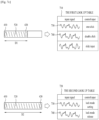
- the HMD device 100 may determine whether the length of the input signal sensing area 520 is more than a threshold length. At this time, if the length of the input signal sensing area 520 is less than the threshold length, the HMD device 100 may acquire a control input on the basis of a first look up table 710. Also, if the length of the input signal sensing area 520 is more than the threshold length, the HMD device 100 may acquire a control input on the basis of a second look up table 720. At this time, the first look up table 710 and the second look up table 720 may have their respective control inputs different from each other for the same input signal.
- the HMD device 100 may allow the first look up table 710 and the second look up table 720 to have different control inputs for the same input signal.
- a first input signal 730 of the first look up table 710 may be a control input for one-click, which selects a menu.
- a first input signal 730 of the second look up table 720 may be a control input that selects a lock mode so as not to select a menu.
- the HMD device 100 may set the look up table differently depending on the length of the input signal sensing area 520, and may acquire different control inputs for the same input signal.
- the look up table may be set by the user. Also, the look up table may be updated by the user or through an external server.
- the HMD device 100 may perform an interface varied depending on the length of the input signal sensing area 520. In more detail, if the input signal sensing area 520 is less than the threshold length, the HMD device 100 may display the interface for menu selection. Also, if the input signal sensing area 520 is more than the threshold length, the HMD device 100 may display an interface that selects a gallery image. In other words, the interface of the HMD device 100 may be set differently depending on the length of the input signal sensing area 520, and is not limited to the aforementioned embodiment.
- the HMD device 100 may have a plurality of threshold lengths. At this time, the HMD device 100 may acquire a respective look up table for each period of the threshold length. Also, as an example, the HMD device 100 may perform a respective interface for each period of the threshold length.
- the HMD device 100 may acquire the first look up table 710. At this time, the length of the input signal sensing area 520 may be determined in accordance with the position where the current reception unit 510 is affixed to the eye-glasses 310. Also, as an example, the HMD device 100 may set the first look up table 710 when the input signal sensing area 520 is located at the right temple differently from the first look up table 710 when the input signal sensing area 520 is located at the left temple.
- the first input signal 730 may be a control input of one-click. At this time, the first input signal 730 may be the input signal generated when the user touches the input signal sensing area 520 one time.
- the second input signal 740 may be a control input of double-click. At this time, the second input signal 740 may be the input signal generated when the user touches the same position of the input signal sensing area 520 twice.
- the first look up table 710 may include a control input corresponding to an input signal of multi-touch, and is not limited to the aforementioned example.
- the HMD device 100 may acquire the second look up table 720.
- the length of the input signal sensing area 520 may be determined in accordance with the position where the current reception unit 510 is affixed to the eye-glasses 310.
- the HMD device 100 may set the second look up table 720 when the input signal sensing area 520 is located at the right temple differently from the second look up table 720 when the input signal sensing area 520 is located at the left temple.
- the first input signal 730 may be a control input that sets a lock mode. At this time, the first input signal 730 may be the input signal generated when the user touches the input signal sensing area 520 one time. Also, if the HMD device 100 acquires the control input on the basis of the second look up table 720, the second input signal 740 may be a control input that unlocks the lock mode. At this time, the second input signal 740 may be the input signal generated when the user touches the same position of the input signal sensing area 520 twice. Also, the second look up table 720 may include a control input corresponding to an input signal of multi-touch, and is not limited to the aforementioned example.
- the HMD device 100 may acquire a look up table varied depending on the length of the input signal sensing area 520. At this time, if the length of the input signal sensing area 520 is less the threshold length, the HMD device 100 may acquire the first look up table 710. Also, if the length of the input signal sensing area 520 is more than the threshold length, the HMD device 100 may acquire the second look up table 720. At this time, the threshold length may be the one that determines the look up table which is acquired. Also, the threshold length may include a constant error, and may be varied by the user. In more detail, the HMD device 100 may set the threshold length to D1. At this time, the HMD device 100 may change the size of D1 through the input of the user.
- the HMD device 100 may include a plurality of threshold lengths.
- the HMD device 100 may acquire different look up tables or may perform different interfaces.
- the HMD device 100 may acquire different look up tables or may perform different interfaces. In other words, the HMD device 100 may acquire a plurality of look up tables or perform a plurality of interfaces by controlling the threshold length.
- FIGs. 8a and 8b are diagrams illustrating a method for enabling an HMD device 100 to acquire a look up table on the basis of a position of an input signal sensing area in accordance with one embodiment of the present specification not encompassed by the wording of the claims but considered to be useful for understanding the invention.
- the input signal sensing area 520 may be located at the temple of the eye-glasses 310 to which the HMD device 100 is affixed.
- the temple of the eye-glasses 310 may mean a portion where a frame of the eye-glasses 310 is located on a profile of the user when the user wears the eye-glasses 310.
- the eye-glasses 310 to which the HMD device 100 is affixed may include the left temple and the right temple.
- the HMD device 100 may set different modes in accordance with the position of the eye-glasses 310.
- the modes may be different user interfaces.
- the modes may have different look up tables at the same user interface, and are not limited to the aforementioned embodiment.
- the HMD device 100 may set a left temple mode.
- the HMD device 100 may set the left temple mode if the HMD device 100 is affixed to the left lens and the input signal sensing area 520 is located at the left temple as the current reception unit 510 is located at the left temple.
- the HMD device 100 may set a right temple mode.
- the HMD device 100 may set the right temple mode if the HMD device 100 is affixed to the right lens and the input signal sensing area 520 is located at the right temple as the current reception unit 510 is located at the right temple.
- the HMD device 100 may acquire a first look up table 810.
- the HMD device 100 may acquire a second look up table 820.
- the HMD device 100 may be operated at a different mode depending on the position of the input signal sensing area 520, and may acquire different look up tables.
- the HMD device 100 may set an interface performed in the left temple mode differently from an interface performed in the right temple mode.
- the HMD device 100 may perform an interface corresponding to menu selection.
- the HMD device 100 may acquire a control input on the basis of the first look up table 810.
- the HMD device 100 may perform an interface that plays music.
- the HMD device 100 may acquire a control input on the basis of the second look up table 820.
- the HMD device 100 may set the interface performed in the left temple mode equally to the interface performed in the right temple mode, and may set the look up tables differently from each other.
- the HMD device 100 may set the interfaces and the look up tables without limitation to the aforementioned embodiment.
- FIG. 8a is a diagram illustrating the first look up table 810 acquired by the HMD device 100 in case of the left temple mode.
- the HMD device 100 may perform a first interface.
- the first interface may be the interface predetermined by the HMD device 100.
- the first interface may be the interface predetermined by the user. If the HMD device 100 performs the first interface, the HMD device 100 may acquire the first look up table 810. If a first input signal 830 is forwarded to the HMD device 100, the HMD device 100 may acquire a control input of one-click on the basis of the first look up table 810. At this time, the first input signal 830 may be a control input generated when the user touches the eye-glasses 310 to which the HMD device 100 is affixed, one time.
- the HMD device 100 may acquire a control input of double-click on the basis of the first look up table 810.
- the second input signal 840 may be a control input generated when the user touches the same position of the eye-glasses 310 to which the HMD device 100 is affixed, twice.
- the HMD device 100 may acquire a control input of a slide on the basis of the first look up table 810.
- the third input signal 850 may be a control input generated when the user touches the eye-glasses 310 to which the HMD device 100 is affixed, through a slide.
- the HMD device 100 may receive the input signal, and may acquire the control input on the basis of the first look up table 810.
- the input signal is not limited to the aforementioned embodiment, and may be varied and set by the user or the HMD device 100.
- FIG. 8b is a diagram illustrating the second look up table 820 acquired by the HMD device 100 in case of the right temple mode.
- the HMD device 100 may perform a second interface.
- the second interface may be the interface that plays music.
- the second interface may be the interface set by the HMD device 100 or the user, and is not limited to the aforementioned embodiment.
- the HMD device 100 may acquire the second look up table 820. If a first input signal 830 is forwarded to the HMD device 100, the HMD device 100 may acquire a control input, which plays music, on the basis of the second look up table 820. At this time, the first input signal 830 may be a control input generated when the user touches the eye-glasses 310 to which the HMD device 100 is affixed, one time.
- the HMD device 100 may acquire a control input, which stops music, on the basis of the second look up table 820.
- the second input signal 840 may be a control input generated when the user touches the same position of the eye-glasses 310 to which the HMD device 100 is affixed, twice.
- the HMD device 100 may acquire a control input, which forwards current music to next music, on the basis of the second look up table 820.
- the third input signal 850 may be a control input generated when the user touches the eye-glasses 310 to which the HMD device 100 is affixed, through a slide.
- the HMD device 100 may receive the input signal, and may acquire the control input on the basis of the second look up table 820.
- the input signal is not limited to the aforementioned embodiment, and may be varied and set by the user or the HMD device 100.
- FIGs. 9a and 9b are diagrams illustrating a method for enabling an HMD device 100 to acquire a look up table in accordance with one embodiment of the present specification not encompassed by the wording of the claims but considered to be useful for understanding the invention.
- the HMD device 100 may further include a communication unit (not shown) that transmits and receives data.
- the communication unit may perform communication by using various protocols to transmit and receive data.
- the communication unit may transmit and receive digital data such as contents by accessing a network through the wire or wireless.
- the HMD device 100 may acquire a look up table on the basis of identification information.
- the HMD device 100 may transmit the identification information to an external server 910 by using the communication unit.
- the external server 910 may be a server that may exchange data with the HMD device 100 by using the communication unit.
- the external server 910 may be an authentication authority that perform authentication.
- the external server 910 may be a separate server set by the user.
- the user may perform authentication for the HMD device 100 by using the external server 910, and may use the HMD device 100 if the HMD device 100 is authenticated. Since the detachable HMD device 100 is detachably provided, the HMD device 100 may be used by a plurality of users, and the users may perform authentication by using a separate external server to identify their data and other security information.
- the external server 910 may transmit the look up table to the HMD device 100 on the basis of the transmitted identification information.
- the HMD device 100 may acquire the look up table through the external server 910.
- the HMD device 100 may acquire the look up table only if the HMD device 100 is authenticated by the external server 910, and may improve a security level.
- the HMD device 100 since the HMD device 100 is manufactured in a micro shape, its space for storing data may be small. Accordingly, the HMD device 100 may store a plurality of look up tables in the external server 910 and acquire information on a look up table, which is required, from the external server 910. Also, for example, the HMD device 100 may update the look up table by using the external server 910.
- the HMD device 100 may perform authentication by using the external server 910 and acquire the look up table.
- the external server 910 may be an authenticated authority.
- the external server 910 may be a server set by the user.
- the HMD device 100 may acquire identification information and transmit the identification information to the external server 910.
- the HMD device 100 may generate an authentication signal 920 on the basis of the identification information.
- the authentication signal 920 may be a signal indicating that the HMD device 100 may acquire the look up table by using the eye-glasses 310 to which the HMD device 100 is affixed.
- the external server 910 may not generate the authentication signal 920 on the basis of the identification information received from the HMD device 100. At this time, the HMD device 100 may not acquire the look up table on the basis of the identification information.
- the authentication signal 920 may be a signal indicating that the HMD device 100 may acquire the look up table on the basis of the identification information and perform a function in accordance with a control input.
- the external server 910 may generate the authentication signal 920 if the identification information is received. Also, as another example, the external server 910 may generate the authentication signal 920 if information on a security key is received from the HMD device 100 together with the identification information. At this time, the security key may mean a value which is predetermined and may mutually be authenticated between the external server 910 and the HMD device 100. As a result, the user may improve a security level for use of the HMD device 100.
- the external server 910 may transmit the authentication signal 920 to the HMD device 100. If the HMD device 100 receives the authentication signal 920, the HMD device 100 may acquire the look up table on the basis of the authentication signal 920 and acquire a control input for the input signal.
- the external server 910 may update identification information that may be acquired by the HMD device 100.
- the external server 910 may transmit identification information on new eye-glasses to the HMD device 100.
- the HMD device 100 may recognize the new eye-glasses 310 on the basis of the transmitted identification information.
- the HMD device 100 may update identification information on the eye-glasses 310 to which the HMD device 100 may be affixed.
- the external server 910 may update the look up table acquired by the HMD device 100.
- the user may acquire the look up table for the eye-glasses having the same identification information by using the external server 910.
- the HMD device 100 may receive the updated look up table from the external server 910 and acquire the control input in accordance with the received look up table.
- the user may control the look up table and the control input for the HMD device 100 by using the external server 910.
- FIG. 10 is a diagram illustrating a method for enabling an HMD device 100 to adjust a focus on the basis of a view of a user in accordance with one embodiment of the present specification not encompassed by the wording of the claims but considered to be useful for understanding the invention.
- the HMD device 100 may adjust a focus of visual information which is displayed on the basis of identification information of the eye-glasses 310.
- the eye-glasses 310 to which the HMD device 100 is affixed have their respective features.
- the eye-glasses 310 to which the HMD device 100 is affixed may have their respective lens sizes and thicknesses different from one another.
- a user 1010 may receive visual information displayed by the HMD device 100 through the lens of the eye-glasses 310. Accordingly, the HMD device 100 may adjust the focus on the visual information which is displayed by considering size and thickness of the lens of the eye-glasses 310 worn by the user 1010.
- the HMD device 100 may provide the visual information in such a manner that focuses different from each other may be provided to each user 1010. At this time, the HMD device 100 may adjust the focus on the visual information on the basis of the thickness and the size of the lens of the eye-glasses 310. Also, as an example, the HMD device 100 may adjust the focus on the visual information which is displayed by using at least one of eyesight information of the user 1010, a distance between eyes of the user and the HMD device 100 and the position where the HMD device 100 is affixed to the eye-glasses.
- the HMD device 100 may acquire information on corrected eyesight of the user 1010 and adjust the focus of the displayed visual information on the basis of the corrected eyesight.
- the HMD device 100 may acquire the corrected eyesight through a user input.
- the corrected eyesight may be eyesight of the user when the user wears the eye-glasses to which the HMD device 100 is affixed.
- the HMD device 100 may adjust the focus on the visual information by adjusting the acquired corrected eyesight and the distance between the HMD device 100 and eyes of the user.
- FIGs. 11a and 11b are diagrams illustrating a method for enabling an HMD device 100 to display visual information in accordance with one embodiment of the present specification not encompassed by the wording of the claims but considered to be useful for understanding the invention.
- the HMD device 100 may acquire a specific one of a plurality of look up tables on the basis of identification information. At this time, the HMD device 100 may display information on the acquired one of the plurality of look up tables. Also, if the HMD device 100 fails to acquire the look up table, the HMD device 100 may display information on that the look up table is not acquired. As a result, the user may identify whether the HMD device 100 affixed to the eye-glasses 310 may perform the control input of the user.
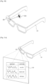
- the HMD device 100 may acquire the look up table 1110 on the basis of the identification information. At this time, the HMD device 100 may display the look up table 1110. The user may control the HMD device 100 through a touch input on the basis of the look up table 1110 which is displayed.
- the HMD device 100 may display recognition error information 1120.
- the recognition error information 1120 may be information corresponding to the case where the HMD device 100 fails to acquire the identification information of the eye-glasses 310.
- the recognition error information 1120 may be information corresponding to the case where the HMD device 100 fails to acquire a look up table corresponding to the identification information.
- the recognition error information 1120 may be information corresponding to the case where the HMD device 100 fails to acquire a control input corresponding to an input signal from the look up table.
- the HMD device 100 may display the recognition error information 1120. Also, as an example, the HMD device 100 may forward the error recognition information 1120 to the user as a feedback.
- the feedback may include, but not limited to, at least one of a visual feedback, an audio feedback, and a tactile feedback.
- FIG. 12 is a diagram illustrating an indicator 1210 displayed on eye-glasses 310 to which an HMD device 100 is affixed in accordance with an unclaimed example.
- the HMD device 100 may be affixed to several parts of a frame of the eye-glasses.
- the HMD device 100 may be affixed to a right lens part of the eye-glasses 310.
- the HMD device 100 may be affixed to a left lens part of the eye-glasses 310.
- the HMD device 100 since the HMD device 100 should provide the user with visual information in a state that the HMD device 100 is affixed to the eye-glasses 310, the HMD device 100 may be affixed to a portion where the user's eyes reach.
- the HMD device 100 may be affixed to a portion where the user's eyes reach most nearly.
- the eye-glasses 310 may include the indicator 1210 that displays the portion to which the HMD device 100 is affixed.
- the indicator 1210 may be displayed as a groove structure so that the HMD device 100 may be affixed to the eye-glasses 310.
- the indicator 1210 may be displayed as a groove structure of the eye-glasses 310, whereby the HMD device 100 may be affixed to the indicator 1210.
- the indicator 1210 may be displayed at the left lens part or the right lens part of the eye-glasses 310.
- the HMD device 100 may be affixed to the indicator 1210 part of the eye-glasses 310 and then may provide the user with the visual information.
- the indicator 1210 may indicate the portion where the current reception unit 510 is affixed.
- the indicator 1210 may be displayed as a groove structure so that the current reception unit 510 may be affixed thereto.
- the indicator 1210 may be displayed on the basis of the length of the aforementioned input signal sensing area 520.
- the indicator 1210 may indicate the threshold length of the input signal sensing area 520 to allow the user to easily identify the look up table acquired by the HMD device 100.
- FIG. 13 is a flow chart illustrating a method for controlling a detachable HMD device 100 in accordance with one embodiment of the present specification not encompassed by the wording of the claims but considered to be useful for understanding the invention.
- the HMD device 100 may detect that the HMD device 100 is affixed to the eye-glasses (S1310). At this time, as described with reference to FIG. 1 , the HMD device 100 may detect whether the HMD device 100 has been affixed to the eye-glasses, by using the affixed detached sensor unit 120.
- the HMD device 100 may generate an electromagnetic pattern.
- the HMD device 100 may generate a current, generate various electromagnetic patterns by controlling an occurrence period of the current, a duration time of the current and strength of the current, and output the electromagnetic pattern to the affixed portion.
- the HMD device 100 may sense variation of the electromagnetic pattern output from the affixed portion by using the affixed detached sensor unit 120.
- the eye-glasses to which the HMD device 100 is affixed may be coated with a material having conductivity.
- the material having conductivity may be, but not limited to, a material, such as Cu, Al, Au, or carbon nanotube, which is coated in the eye-glasses to flow a micro current.
- the HMD device 100 may detect that the HMD device 100 has been affixed to the eye-glasses by sensing that the output electromagnetic pattern is varied by the eye-glasses coated with the conductive material. Also, the HMD device 100 may detect that the eye-glasses has been affixed to the HMD device 100 by sensing magnetic field varied by the eye-glasses coated with the conductive material. Also, the HMD device 100 may detect that the HMD device 100 has been affixed to the eye-glasses by using a radio frequency identification (RFID) signal, a bar code, a QR code, etc. In accordance with the present specification, the HMD device 100 may include, but not limited to, a sensor that may detect that the HMD device 100 is affixed to the eye-glasses.
- RFID radio frequency identification
- the HMD device 100 may acquire identification information of the affixed eye-glasses 310 (S1320).
- the identification information may mean information identified per eye-glasses 310 to which the HMD device 100 is affixed.
- the identification information may include at least one of a type of the eye-glasses, appearance of the eye-glasses, parts of the eye-glasses, a material coated in the eye-glasses, conductivity of the eye-glasses, a length of an area of the eye-glasses coated with a conductive material, a lens size of the eye-glasses, and a thickness of the eye-glasses.
- the identification information may include information on the eye-glasses to which the HMD device 100 is affixed. The identification information is not limited to the aforementioned embodiment.
- the HMD device 100 may acquire he identification information 640 by using at least one of variation of an electric signal, the RFID signal, the bar code, and the QR code. Also, the HMD device 100 may acquire the identification information 640 by means of a value which is predetermined between the eye-glasses 310 and the HMD device 100.
- the identification information 640 may be acquired without limitation to the aforementioned embodiment.
- the HMD device 100 may acquire a look up table related to the identification information (S1330).
- the look up table 650 may be a set of predetermined values corresponding to a given input signal.
- the look up table 650 may be a value corresponding to a control input matched with the input signal which is generated when the user 430 touches the eye-glasses 310.
- the look up table 650 may be set on the basis of the acquired identification information 640.
- the look up table 650 may be set differently depending on the conductive material coated in the eye-glasses 310 and the length of the eye-glasses coated with the conductive material among the identification information 640.
- the HMD device 100 may set the look up table on the basis of the length of the input signal sensing area 520.
- the input signal sensing area 520 may be an area between the first contact point 410 and the second contact point 420.
- the input signal sensing area 520 may be an area where a current flows in the eye-glasses 310, and may mean an area where the input signal touched by the user may be detected.
- the HMD device 100 may set the look up table on the basis of the position of the input signal sensing area 520. Also, the HMD device 100 may acquire the look up table from the external server.
- the HMD device 100 may acquire the input signal generated when the eye-glasses to which the HMD device 100 is affixed is touched (S1340). At this time, as described with reference to FIG. 1 , the HMD device 100 may detect the input signal varied when the eye-glasses are touched using the sensor unit. In more detail, if the eye-glasses are touched, the HMD device 100 may sense that electric conductivity or electromagnetic pattern of the conductive material coated in the eye-glasses is varied, thereby detecting the input signal corresponding to the touched area of the eye-glasses.
- the HMD device 100 may include a first contact point for applying a current and a second contact point for receiving the current applied from the first contact point.
- the HMD device 100 may include a current reception unit. At this time, the current reception unit may receive the current applied from the first contact point.
- the current reception unit may include the second contact point. The current reception unit may control the input signal sensing area where the input signal is detected, by controlling the position of the second contact point.
- the HMD device 100 may acquire the control input related to the input signal from the look up table (S1350).
- the control input may be a control input for an interface performed by the HMD device 100.
- the HMD device 100 may acquire the control input, which performs one-click, from the look up table 650.
- the HMD device 100 may acquire the control input, which performs a slide, from the look up table 650.
- the HMD device 100 may acquire a control input corresponding to multi-touch from the look up table 650.
- the look up table 650 may be set to include the control input corresponding to the aforementioned embodiments.
- the look up table 650 may be varied by the user or the HMD device 100 without limitation to the aforementioned embodiment.
- the HMD device 100 may perform a function corresponding to the control input (S1360).
- the function may be a command that controls the user interface performed by the HMD device 100.
- the HMD device 100 may perform a function that stops the music, which is being played, or replays the music.
- the HMD device 100 displays a menu and acquires the control input, which performs one-click, from the look up table 650, the HMD device 100 may perform a function that selects an icon in a menu.
- the HMD device 100 may control the function performed by the control input by considering the user interface which is performed.
- the HMD device 100 and the method for controlling the same may be performed in a recording medium, which can be read by a controller provided in a network device, as a code that can be read by the controller.
- the recording medium that can be read by the controller includes all kinds of recording media in which data that can be read by the controller are stored. Examples of the recording medium include a ROM, a RAM, a CD-ROM, a magnetic tape, a floppy disk, and an optical data memory. Also, another example of the recording medium may be performed in a type of carrier wave such as transmission through Internet. Also, the recording medium that can be read by the controller may be distributed in a computer system connected thereto through the network, whereby codes that can be read by the controller may be stored and performed in a distributive mode.
- the present invention is totally or partially applicable to electronic devices.
Landscapes
- Engineering & Computer Science (AREA)
- Physics & Mathematics (AREA)
- General Engineering & Computer Science (AREA)
- Theoretical Computer Science (AREA)
- General Physics & Mathematics (AREA)
- Human Computer Interaction (AREA)
- Optics & Photonics (AREA)
- Eyeglasses (AREA)
- User Interface Of Digital Computer (AREA)
Claims (11)
- Eine abnehmbare kopfmontierte Anzeige, HMD, -Vorrichtung (100), die aufweist:eine Anzeigeeinheit (110), die konfiguriert ist, visuelle Informationen anzuzeigen;eine erste Sensoreinheit (120), die konfiguriert ist, zu erfassen, ob die HMD-Vorrichtung (100) an einem befestigten Abschnitt an einer Brille (310) befestigt worden ist, wobei der befestigte Abschnitt ein Abschnitt ist, an dem die HMD-Vorrichtung (100) an der Brille (310) befestigt ist, wobei die HMD-Vorrichtung (100) von einer Linse oder einem Bügelteil der Brille (310) trennbar und daran befestigbar ist;eine zweite Sensoreinheit (130), die konfiguriert ist, ein Eingangssignal zu erfassen, das erzeugt wird, wenn die Brille (310), an der die HMD-Vorrichtung (100) befestigt ist, von einem Benutzer (430) berührt wird; undeine Steuerung (140), die konfiguriert ist, die Anzeigeeinheit (110), die erste Sensoreinheit (120) und die zweite Sensoreinheit (130) zu steuern,wobei die Steuerung (140) ferner konfiguriert ist, um:wenn die HMD-Vorrichtung (100) erkennt, dass die HMD-Vorrichtung (100) an der Brille (310) befestigt ist, Identifikationsinformationen der Brille (310) zu erlangen, Benutzerinformationen des Benutzers (430) der Brille (310) zu erlangen, eine Nachschlagetabelle (650) auf der Grundlage der Identifikationsinformationen einzustellen, wobei die Nachschlagetabelle (650) eine Tabelle ist, die einen Satz vorbestimmter Werte für eine Steuereingabe umfasst, die mit einem gegebenen Eingangssignal übereinstimmt, das von der zweiten Sensoreinheit (130) erfasst wird, das erfasste Eingangssignal von der zweiten Sensoreinheit (130) zu empfangen, eine Steuereingabe, die mit dem erfassten Eingangssignal übereinstimmt, aus der Nachschlagetabelle (650) zu erlangen, und eine Funktion in Übereinstimmung mit der erlangten Steuereingabe, die mit dem erfassten Eingangssignal übereinstimmt, auszuführen,wobei die Steuerung ferner konfiguriert ist, wenn die HMD-Vorrichtung (100) erkennt, dass die HMD-Vorrichtung (100) an der Brille (310) befestigt ist, einen Fokus von visuellen Informationen, die auf der Grundlage der Identifikationsinformation der Brille (310) angezeigt wird, einzustellen, wobei die Identifikationsinformation der Brille eine Linsengröße der Brille (310) umfasst,wobei die HDM-Vorrichtung (100) ferner einen ersten Kontaktpunkt (410) zum Anlegen eines Stroms an die Brille (310) und einen zweiten Kontaktpunkt (420) zum Empfangen des von dem ersten Kontaktpunkt (410) angelegten Stroms umfasst, wobei eine Stromempfangseinheit (510), die den zweiten Kontaktpunkt (420) enthält, über einen Draht mit der HMD-Vorrichtung (100) verbunden ist,wobei die Steuerung (140) ferner konfiguriert ist, einen Bereich zwischen dem ersten Kontaktpunkt (410) und dem zweiten Kontaktpunkt (420) als einen Eingangssignal-Erfassungsbereich (520) festzulegen, der das Eingangssignal erfasst,wobei eine Länge des Eingangssignal-Erfassungsbereichs (520) auf der Grundlage einer Stelle, an der die Stromempfangseinheit (510) an der Brille (310) angebracht ist, einstellbar ist,wobei die Steuerung (140) ferner konfiguriert ist, die Nachschlagetabelle (650) auf der Grundlage der Länge des Eingangssignal-Erfassungsbereichs (520) zu bestimmen,wobei, falls die Länge des Eingangssignal-Erfassungsbereichs (520) kleiner als eine Schwellenlänge ist, die Steuereingabe in Bezug auf das Eingangssignal aus einer ersten Nachschlagetabelle (710) erfasst wird, undwobei, falls die Länge des Eingangssignal-Erfassungsbereichs (520) größer als die Schwellenlänge ist, die Steuereingabe in Bezug auf das Eingangssignal aus einer zweiten Nachschlagetabelle (720) erfasst wird.
- Die HMD-Vorrichtung (100) nach Anspruch 1, wobei die zweite Sensoreinheit (130) das Eingangssignal erfasst, das erzeugt wird, wenn die Brille (310), an der die HMD-Vorrichtung (100) befestigt ist, berührt wird, und
wobei das Eingangssignal auf der Grundlage des von dem ersten Kontaktpunkt (410) angelegten und von dem zweiten Kontaktpunkt (420) empfangenen Stroms erfasst wird. - Die HMD-Vorrichtung (100) nach Anspruch 1, wobei die Brille (310) einen linken Bügel und einen rechten Bügel umfasst,
wobei die Steuerung (140) ferner konfiguriert ist, um:falls sich der Eingangssignal-Erfassungsbereich (520) an dem linken Bügel befindet, einen linken Bügelmodus einzustellen,falls sich der Eingangssignal-Erfassungsbereich (520) an dem rechten Bügel befindet, einen rechten Bügelmodus einzustellen und,wobei die Steuereingabe, die sich auf das Eingangssignal bezieht, von der ersten Nachschlagetabelle (710) in dem linken Bügelmodus erfasst wird und die Steuereingabe, die sich auf das Eingangssignal bezieht, von der zweiten Nachschlagetabelle (720) in dem rechten Bügelmodus erfasst wird. - Die HMD-Vorrichtung (100) nach einem der Ansprüche 1 bis 3, wobei die Steuerung (140) ferner konfiguriert ist, um:
die Identifizierungsinformation unter Verwendung von mindestens einem von einem Strichcode, einem QR-Code oder einem RFID-Signal zu erfassen. - Die HMD-Vorrichtung (100) nach einem der Ansprüche 1 bis 4, ferner umfassend eine Kommunikationseinheit, die konfiguriert ist, die Identifikationsinformation, die Nachschlagetabelle (650) und ein Authentifizierungssignal zu senden und zu empfangen.
- Die HMD-Vorrichtung (100) nach Anspruch 5, wobei die Steuerung (140) ferner konfiguriert ist, die Nachschlagetabelle (650) in Bezug auf die Identifikationsinformation von einem externen Server (910) unter Verwendung der Kommunikationseinheit abzurufen.
- HMD-Vorrichtung (100) nach Anspruch 5, wobei die Steuerung (140) ferner konfiguriert ist, die Identifikationsinformation an den externen Server (910) zu übertragen, das von dem externen Server (910) übertragene Authentifizierungssignal auf der Grundlage der Identifikationsinformation zu erfassen und,
falls die Brille (310) auf der Grundlage des Authentifizierungssignals authentifiziert wird, die Nachschlagetabelle (650) abzurufen. - Die HMD-Vorrichtung (100) nach einem der Ansprüche 1 bis 7, wobei die Steuereinheit (140) ferner konfiguriert ist, einen Ordner zum Speichern von Daten auf der Grundlage der Benutzerinformationen zu erzeugen und die Daten, die Informationen umfassen, die der von dem Benutzer (430) in einem Zustand, in dem die HMD-Vorrichtung (100) an der Brille (310) befestigt ist, ausgeführten Funktion entsprechen, in dem Ordner zu speichern.
- Die HMD-Vorrichtung (100) nach einem der Ansprüche 1 bis 8, wobei die Steuerung (140) ferner konfiguriert ist, um:
falls eine Vielzahl von Nachschlagetabellen (650) bereitgestellt wird, die Nachschlagetabelle (650) mit der durch eine Benutzereingabe eingegebenen Identifikationsinformation abgleichen. - Die HMD-Vorrichtung (100) nach einem der Ansprüche 1 bis 9, wobei die zweite Sensoreinheit (130) ferner Merkmalsinformationen über die Brille (310), an der die HMD-Vorrichtung (100) befestigt ist, erfasst, undwobei die Steuerung (140) ferner konfiguriert ist, die erfassten Merkmalsinformationen von der zweiten Sensoreinheit (130) zu empfangen und die Merkmalsinformationen mit der Identifikationsinformation abzugleichen,wobei, falls die Identifikationsinformation mit den Merkmalsinformationen übereinstimmt, die Nachschlagetabelle (650) auf der Grundlage der Identifikationsinformation aufrechterhalten wird, undwobei, falls die Identifikationsinformation nicht mit den Merkmalsinformationen übereinstimmt, die Nachschlagetabelle (650) auf der Grundlage der Merkmalsinformationen aktualisiert wird.
- Verfahren zum Steuern einer Anzeigeeinheit, einer ersten Sensoreinheit und einer zweiten Sensoreinheit einer abnehmbaren kopfmontierten Anzeige, HMD, - Vorrichtung (100) durch eine Steuerung (140) der HMD-Vorrichtung, wobei das Verfahren umfasst:Anzeigen von visuellen Informationen über die Anzeigeeinheit; undErfassen (S1310) durch die erste Sensoreinheit, dass die HMD-Vorrichtung (100) an einer Brille (310) an einem befestigten Abschnitt befestigt ist, wobei der befestigte Abschnitt ein Abschnitt ist, an dem die HMD-Vorrichtung an der Brille befestigt ist, wobei die HMD-Vorrichtung (100) von einer Linse oder einem Bügelteil der Brille trennbar und daran befestigbar ist;wobei, wenn die HMD-Vorrichtung erkennt, dass die HMD-Vorrichtung an der Brille befestigt ist, die Steuerung die Schritte durchführt:Erlangen (S1320) von Identifikationsinformation der Brille;Erlangen von Benutzerinformationen eines Brillenträgers;Festlegen (S1330) einer Nachschlagetabelle auf der Grundlage der Identifikationsinformation, wobei die Nachschlagetabelle (20) eine Tabelle ist, die einen Satz von vorbestimmten Werten für einen Steuereingang umfasst, der mit einem gegebenen Eingangssignal übereinstimmt, das von der zweiten Sensoreinheit erfasst wird;Empfangen (S1340) eines Eingangssignals von der Sensoreinheit, das erzeugt wird, wenn die Brille, an der die HMD-Vorrichtung befestigt ist, berührt wird;Erlangen (S1350) einer Steuereingabe, die mit dem erkannten Eingangssignal aus der Nachschlagetabelle übereinstimmt;Ausführen (S1360) einer Funktion in Übereinstimmung mit der erlangten Steuereingabe, die mit dem erfassten Eingangssignal übereinstimmt; undEinstellen eines Fokus von visueller Information, die auf der Basis der Identifikationsinformation der Brille (310) angezeigt wird; wobei die Identifikationsinformation der Brille (310) eine Linsengröße der Brille (310) einschließt, wobei die HDM-Vorrichtung (100) ferner einen ersten Kontaktpunkt (410) zum Anlegen eines Stroms an die Brille (310) und einen zweiten Kontaktpunkt (420) zum Empfangen des von dem ersten Kontaktpunkt (410) angelegten Stroms umfasst, wobei eine Stromempfangseinheit (510), die den zweiten Kontaktpunkt (420) einschließt, mit der HMD-Vorrichtung (100) durch einen Draht verbunden ist,Einstellen eines Bereichs zwischen dem ersten Kontaktpunkt (410) der HDM-Vorrichtung (100) und dem zweiten Kontaktpunkt (420) der HDM-Vorrichtung (100) als ein Eingangssignal-Erfassungsbereich (520), der das Eingangssignal erfasst, und wobei eine Länge des Eingangssignal-Erfassungsbereichs (520) auf der Grundlage einer Stelle, an der die Stromempfangseinheit (510) an der Brille (310) befestigt ist, einstellbar ist; undBestimmen der Nachschlagetabelle (650) auf der Grundlage der Länge des Eingangssignal-Erfassungsbereichs (520), wobei, falls die Länge des Eingangssignal-Erfassungsbereichs (520) kleiner als eine Schwellenlänge ist, die mit dem Eingangssignal zusammenhängende Steuereingabe aus einer ersten Nachschlagetabelle (710) erfasst wird, und wobei, falls die Länge des Eingangssignal-Erfassungsbereichs (520) größer als die Schwellenlänge ist, die mit dem Eingangssignal zusammenhängende Steuereingabe aus einer zweiten Nachschlagetabelle (720) erfasst wird.
Applications Claiming Priority (3)
| Application Number | Priority Date | Filing Date | Title |
|---|---|---|---|
| KR1020140005115A KR102201736B1 (ko) | 2014-01-15 | 2014-01-15 | 탈착형 헤드 마운티드 디스플레이 디바이스 및 그 제어 방법 |
| US14/212,962 US9348142B2 (en) | 2014-01-15 | 2014-03-14 | Detachable head mount display device and method for controlling the same |
| PCT/KR2014/002311 WO2015108234A1 (en) | 2014-01-15 | 2014-03-19 | Detachable head mount display device and method for controlling the same |
Publications (3)
| Publication Number | Publication Date |
|---|---|
| EP3095005A1 EP3095005A1 (de) | 2016-11-23 |
| EP3095005A4 EP3095005A4 (de) | 2017-08-09 |
| EP3095005B1 true EP3095005B1 (de) | 2024-02-14 |
Family
ID=53521365
Family Applications (1)
| Application Number | Title | Priority Date | Filing Date |
|---|---|---|---|
| EP14878991.0A Active EP3095005B1 (de) | 2014-01-15 | 2014-03-19 | Abnehmbare kopfmontierte anzeigevorrichtung und verfahren zur steuerung davon |
Country Status (4)
| Country | Link |
|---|---|
| US (2) | US9348142B2 (de) |
| EP (1) | EP3095005B1 (de) |
| KR (1) | KR102201736B1 (de) |
| WO (1) | WO2015108234A1 (de) |
Families Citing this family (17)
| Publication number | Priority date | Publication date | Assignee | Title |
|---|---|---|---|---|
| JP2015158747A (ja) * | 2014-02-21 | 2015-09-03 | ソニー株式会社 | 制御装置、情報処理装置、制御方法、情報処理方法、情報処理システム、およびウェアラブル機器 |
| US9870049B2 (en) | 2015-07-31 | 2018-01-16 | Google Llc | Reflective lenses to auto-calibrate a wearable system |
| US9298283B1 (en) | 2015-09-10 | 2016-03-29 | Connectivity Labs Inc. | Sedentary virtual reality method and systems |
| US10691250B2 (en) * | 2015-09-24 | 2020-06-23 | Sony Corporation | Information processing device, information processing method, and program for preventing reflection of an operation in an output |
| GB2557569B (en) * | 2016-09-09 | 2022-07-06 | Displaylink Uk Ltd | Adjusting display data |
| US10739850B2 (en) * | 2017-09-29 | 2020-08-11 | Sony Interactive Entertainment Inc. | Prescription glasses with eye gaze tracking and electro optical signaling to a HMD |
| MX2021005719A (es) * | 2018-11-16 | 2021-08-11 | Mira Labs Inc | Detección de configuración de cascos de lentes reflectantes. |
| CN110308560B (zh) * | 2019-07-03 | 2022-09-30 | 南京玛克威信息科技有限公司 | Vr设备的控制方法 |
| US12507006B2 (en) * | 2020-12-04 | 2025-12-23 | Universal City Studios Llc | System and method for private audio channels |
| US11693477B2 (en) | 2020-12-07 | 2023-07-04 | Samsung Electronics Co., Ltd. | Lens clip for receiving user lens and head mounted electronic device for detecting whether user lens is inserted into lens clip |
| US11880542B2 (en) * | 2021-05-19 | 2024-01-23 | Snap Inc. | Touchpad input for augmented reality display device |
| KR102766471B1 (ko) * | 2021-05-19 | 2025-02-12 | 스냅 인코포레이티드 | 증강 현실 디스플레이 디바이스를 위한 터치패드 입력 |
| US11928306B2 (en) * | 2021-05-19 | 2024-03-12 | Snap Inc. | Touchpad navigation for augmented reality display device |
| CN117999526A (zh) * | 2021-09-23 | 2024-05-07 | 苹果公司 | 可头戴式显示器和光密封面罩 |
| KR102796018B1 (ko) | 2021-11-25 | 2025-04-16 | 오영휘 | 안경 탈장착이 가능한 헤드 마운트 디스플레이 |
| KR102899273B1 (ko) | 2022-11-11 | 2025-12-12 | 박서진 | 헤드 마운트 디스플레이 |
| CN116022158B (zh) * | 2023-03-30 | 2023-06-06 | 深圳曦华科技有限公司 | 多域控制器协作的驾驶安全控制方法及装置 |
Family Cites Families (12)
| Publication number | Priority date | Publication date | Assignee | Title |
|---|---|---|---|---|
| US6204974B1 (en) * | 1996-10-08 | 2001-03-20 | The Microoptical Corporation | Compact image display system for eyeglasses or other head-borne frames |
| JP4198069B2 (ja) * | 2004-01-07 | 2008-12-17 | シャープ株式会社 | 電子機器 |
| DE102004026825A1 (de) * | 2004-06-02 | 2005-12-22 | Carl Zeiss | Modulares System zum Aufbau einer auf dem Kopf eines Benutzers zu tragenden Anzeigevorrichtung |
| JP2007148131A (ja) * | 2005-11-29 | 2007-06-14 | Kazuyuki Hogo | ヘッドマウントディスプレイ |
| JP5030595B2 (ja) * | 2007-01-09 | 2012-09-19 | スカラ株式会社 | ヘッドマウントディスプレイ |
| JP5212901B2 (ja) | 2008-09-25 | 2013-06-19 | ブラザー工業株式会社 | 眼鏡型の画像表示装置 |
| US8957835B2 (en) * | 2008-09-30 | 2015-02-17 | Apple Inc. | Head-mounted display apparatus for retaining a portable electronic device with display |
| JP5126682B2 (ja) | 2008-12-10 | 2013-01-23 | ブラザー工業株式会社 | ヘッドマウントディスプレイ |
| EP2619749A4 (de) * | 2010-09-21 | 2017-11-15 | 4IIII Innovations Inc. | Kopfmontierte rundumsicht-anzeigesysteme und -verfahren |
| KR101841105B1 (ko) * | 2011-01-04 | 2018-05-04 | 엘지이노텍 주식회사 | 헤드마운트 디스플레이 장치 |
| US8203502B1 (en) | 2011-05-25 | 2012-06-19 | Google Inc. | Wearable heads-up display with integrated finger-tracking input sensor |
| JP5884502B2 (ja) | 2012-01-18 | 2016-03-15 | ソニー株式会社 | ヘッドマウントディスプレイ |
-
2014
- 2014-01-15 KR KR1020140005115A patent/KR102201736B1/ko active Active
- 2014-03-14 US US14/212,962 patent/US9348142B2/en active Active
- 2014-03-19 EP EP14878991.0A patent/EP3095005B1/de active Active
- 2014-03-19 WO PCT/KR2014/002311 patent/WO2015108234A1/en not_active Ceased
-
2016
- 2016-04-29 US US15/142,078 patent/US9599823B2/en active Active
Also Published As
| Publication number | Publication date |
|---|---|
| KR102201736B1 (ko) | 2021-01-12 |
| WO2015108234A1 (en) | 2015-07-23 |
| EP3095005A4 (de) | 2017-08-09 |
| US9348142B2 (en) | 2016-05-24 |
| KR20150085342A (ko) | 2015-07-23 |
| US20160246060A1 (en) | 2016-08-25 |
| US9599823B2 (en) | 2017-03-21 |
| US20150199064A1 (en) | 2015-07-16 |
| EP3095005A1 (de) | 2016-11-23 |
Similar Documents
| Publication | Publication Date | Title |
|---|---|---|
| EP3095005B1 (de) | Abnehmbare kopfmontierte anzeigevorrichtung und verfahren zur steuerung davon | |
| CN105259654B (zh) | 眼镜式终端及其控制方法 | |
| US10757335B2 (en) | Mobile terminal | |
| US10712901B2 (en) | Gesture-based content sharing in artificial reality environments | |
| CN111630477B (zh) | 提供增强现实服务的设备及其操作方法 | |
| TWI730824B (zh) | 處理第一裝置上的畫面的方法、使用包括物件的第一裝置來處理畫面的方法、與使用裝置來處理畫面的設備 | |
| EP3163401B1 (de) | Mobiles endgerät und steuerungsverfahren dafür | |
| EP2759922B1 (de) | Verfahren zur Durchführung einer Vorrichtungsfunktion auf Basis von einer Vorrichtungsbewegung und Vorrichtung zur Durchführung des Verfahrens | |
| US9377869B2 (en) | Unlocking a head mountable device | |
| CN103970265B (zh) | 具有触觉反馈的增强现实用户接口 | |
| CN117356116A (zh) | 用于定位可穿戴设备和向可穿戴设备递送内容的信标 | |
| US9607169B2 (en) | Mobile terminal and method for controlling the same | |
| CN104808784B (zh) | 移动终端及其控制方法 | |
| CN104321730B (zh) | 3d图形用户接口 | |
| EP3037924A1 (de) | Augmented reality anzeige und handschuh mit markern als benutzereingabevorrichtung | |
| US10896545B1 (en) | Near eye display interface for artificial reality applications | |
| US20170115736A1 (en) | Photo-Based Unlock Patterns | |
| KR20150110257A (ko) | 웨어러블 디바이스에서 가상의 입력 인터페이스를 제공하는 방법 및 이를 위한 웨어러블 디바이스 | |
| CN106067833A (zh) | 移动终端及其控制方法 | |
| CN110546601A (zh) | 信息处理装置、信息处理方法和程序 | |
| KR20160015972A (ko) | 웨어러블 디바이스 및 그 제어 방법 | |
| US10579260B2 (en) | Mobile terminal having display screen and communication system thereof for unlocking connected devices using an operation pattern | |
| CN109074435A (zh) | 用于提供用户信息的电子设备和方法 | |
| CN106664398A (zh) | 具有与虚拟对象的深度协作的认可范围的显示装置及其控制方法 | |
| US9998671B2 (en) | Electronic apparatus, method of controlling the same, and computer-readable recording medium |
Legal Events
| Date | Code | Title | Description |
|---|---|---|---|
| PUAI | Public reference made under article 153(3) epc to a published international application that has entered the european phase |
Free format text: ORIGINAL CODE: 0009012 |
|
| 17P | Request for examination filed |
Effective date: 20160617 |
|
| AK | Designated contracting states |
Kind code of ref document: A1 Designated state(s): AL AT BE BG CH CY CZ DE DK EE ES FI FR GB GR HR HU IE IS IT LI LT LU LV MC MK MT NL NO PL PT RO RS SE SI SK SM TR |
|
| AX | Request for extension of the european patent |
Extension state: BA ME |
|
| DAX | Request for extension of the european patent (deleted) | ||
| A4 | Supplementary search report drawn up and despatched |
Effective date: 20170707 |
|
| RIC1 | Information provided on ipc code assigned before grant |
Ipc: G02B 27/01 20060101AFI20170704BHEP Ipc: G06F 3/038 20130101ALI20170704BHEP Ipc: G06F 3/0354 20130101ALI20170704BHEP |
|
| STAA | Information on the status of an ep patent application or granted ep patent |
Free format text: STATUS: EXAMINATION IS IN PROGRESS |
|
| 17Q | First examination report despatched |
Effective date: 20190905 |
|
| REG | Reference to a national code |
Ref country code: DE Ref legal event code: R079 Free format text: PREVIOUS MAIN CLASS: G02B0027020000 Ipc: G02B0027010000 Ref country code: DE Ref legal event code: R079 Ref document number: 602014089499 Country of ref document: DE Free format text: PREVIOUS MAIN CLASS: G02B0027020000 Ipc: G02B0027010000 |
|
| GRAP | Despatch of communication of intention to grant a patent |
Free format text: ORIGINAL CODE: EPIDOSNIGR1 |
|
| STAA | Information on the status of an ep patent application or granted ep patent |
Free format text: STATUS: GRANT OF PATENT IS INTENDED |
|
| RIC1 | Information provided on ipc code assigned before grant |
Ipc: G06F 3/041 20060101ALI20230828BHEP Ipc: G06F 3/038 20130101ALI20230828BHEP Ipc: G06F 3/0354 20130101ALI20230828BHEP Ipc: G02B 27/01 20060101AFI20230828BHEP |
|
| INTG | Intention to grant announced |
Effective date: 20230914 |
|
| GRAS | Grant fee paid |
Free format text: ORIGINAL CODE: EPIDOSNIGR3 |
|
| GRAA | (expected) grant |
Free format text: ORIGINAL CODE: 0009210 |
|
| STAA | Information on the status of an ep patent application or granted ep patent |
Free format text: STATUS: THE PATENT HAS BEEN GRANTED |
|
| AK | Designated contracting states |
Kind code of ref document: B1 Designated state(s): AL AT BE BG CH CY CZ DE DK EE ES FI FR GB GR HR HU IE IS IT LI LT LU LV MC MK MT NL NO PL PT RO RS SE SI SK SM TR |
|
| REG | Reference to a national code |
Ref country code: GB Ref legal event code: FG4D |
|
| REG | Reference to a national code |
Ref country code: CH Ref legal event code: EP |
|
| REG | Reference to a national code |
Ref country code: DE Ref legal event code: R096 Ref document number: 602014089499 Country of ref document: DE |
|
| REG | Reference to a national code |
Ref country code: IE Ref legal event code: FG4D |
|
| REG | Reference to a national code |
Ref country code: LT Ref legal event code: MG9D |
|
| REG | Reference to a national code |
Ref country code: NL Ref legal event code: MP Effective date: 20240214 |
|
| PG25 | Lapsed in a contracting state [announced via postgrant information from national office to epo] |
Ref country code: IS Free format text: LAPSE BECAUSE OF FAILURE TO SUBMIT A TRANSLATION OF THE DESCRIPTION OR TO PAY THE FEE WITHIN THE PRESCRIBED TIME-LIMIT Effective date: 20240614 |
|
| PG25 | Lapsed in a contracting state [announced via postgrant information from national office to epo] |
Ref country code: LT Free format text: LAPSE BECAUSE OF FAILURE TO SUBMIT A TRANSLATION OF THE DESCRIPTION OR TO PAY THE FEE WITHIN THE PRESCRIBED TIME-LIMIT Effective date: 20240214 |
|
| PG25 | Lapsed in a contracting state [announced via postgrant information from national office to epo] |
Ref country code: GR Free format text: LAPSE BECAUSE OF FAILURE TO SUBMIT A TRANSLATION OF THE DESCRIPTION OR TO PAY THE FEE WITHIN THE PRESCRIBED TIME-LIMIT Effective date: 20240515 |
|
| REG | Reference to a national code |
Ref country code: AT Ref legal event code: MK05 Ref document number: 1657521 Country of ref document: AT Kind code of ref document: T Effective date: 20240214 |
|
| PG25 | Lapsed in a contracting state [announced via postgrant information from national office to epo] |
Ref country code: HR Free format text: LAPSE BECAUSE OF FAILURE TO SUBMIT A TRANSLATION OF THE DESCRIPTION OR TO PAY THE FEE WITHIN THE PRESCRIBED TIME-LIMIT Effective date: 20240214 Ref country code: NL Free format text: LAPSE BECAUSE OF FAILURE TO SUBMIT A TRANSLATION OF THE DESCRIPTION OR TO PAY THE FEE WITHIN THE PRESCRIBED TIME-LIMIT Effective date: 20240214 Ref country code: RS Free format text: LAPSE BECAUSE OF FAILURE TO SUBMIT A TRANSLATION OF THE DESCRIPTION OR TO PAY THE FEE WITHIN THE PRESCRIBED TIME-LIMIT Effective date: 20240514 |
|
| PG25 | Lapsed in a contracting state [announced via postgrant information from national office to epo] |
Ref country code: ES Free format text: LAPSE BECAUSE OF FAILURE TO SUBMIT A TRANSLATION OF THE DESCRIPTION OR TO PAY THE FEE WITHIN THE PRESCRIBED TIME-LIMIT Effective date: 20240214 |
|
| PG25 | Lapsed in a contracting state [announced via postgrant information from national office to epo] |
Ref country code: AT Free format text: LAPSE BECAUSE OF FAILURE TO SUBMIT A TRANSLATION OF THE DESCRIPTION OR TO PAY THE FEE WITHIN THE PRESCRIBED TIME-LIMIT Effective date: 20240214 |
|
| PG25 | Lapsed in a contracting state [announced via postgrant information from national office to epo] |
Ref country code: RS Free format text: LAPSE BECAUSE OF FAILURE TO SUBMIT A TRANSLATION OF THE DESCRIPTION OR TO PAY THE FEE WITHIN THE PRESCRIBED TIME-LIMIT Effective date: 20240514 Ref country code: NO Free format text: LAPSE BECAUSE OF FAILURE TO SUBMIT A TRANSLATION OF THE DESCRIPTION OR TO PAY THE FEE WITHIN THE PRESCRIBED TIME-LIMIT Effective date: 20240514 Ref country code: NL Free format text: LAPSE BECAUSE OF FAILURE TO SUBMIT A TRANSLATION OF THE DESCRIPTION OR TO PAY THE FEE WITHIN THE PRESCRIBED TIME-LIMIT Effective date: 20240214 Ref country code: LT Free format text: LAPSE BECAUSE OF FAILURE TO SUBMIT A TRANSLATION OF THE DESCRIPTION OR TO PAY THE FEE WITHIN THE PRESCRIBED TIME-LIMIT Effective date: 20240214 Ref country code: IS Free format text: LAPSE BECAUSE OF FAILURE TO SUBMIT A TRANSLATION OF THE DESCRIPTION OR TO PAY THE FEE WITHIN THE PRESCRIBED TIME-LIMIT Effective date: 20240614 Ref country code: HR Free format text: LAPSE BECAUSE OF FAILURE TO SUBMIT A TRANSLATION OF THE DESCRIPTION OR TO PAY THE FEE WITHIN THE PRESCRIBED TIME-LIMIT Effective date: 20240214 Ref country code: GR Free format text: LAPSE BECAUSE OF FAILURE TO SUBMIT A TRANSLATION OF THE DESCRIPTION OR TO PAY THE FEE WITHIN THE PRESCRIBED TIME-LIMIT Effective date: 20240515 Ref country code: FI Free format text: LAPSE BECAUSE OF FAILURE TO SUBMIT A TRANSLATION OF THE DESCRIPTION OR TO PAY THE FEE WITHIN THE PRESCRIBED TIME-LIMIT Effective date: 20240214 Ref country code: ES Free format text: LAPSE BECAUSE OF FAILURE TO SUBMIT A TRANSLATION OF THE DESCRIPTION OR TO PAY THE FEE WITHIN THE PRESCRIBED TIME-LIMIT Effective date: 20240214 Ref country code: BG Free format text: LAPSE BECAUSE OF FAILURE TO SUBMIT A TRANSLATION OF THE DESCRIPTION OR TO PAY THE FEE WITHIN THE PRESCRIBED TIME-LIMIT Effective date: 20240214 Ref country code: AT Free format text: LAPSE BECAUSE OF FAILURE TO SUBMIT A TRANSLATION OF THE DESCRIPTION OR TO PAY THE FEE WITHIN THE PRESCRIBED TIME-LIMIT Effective date: 20240214 |
|
| PG25 | Lapsed in a contracting state [announced via postgrant information from national office to epo] |
Ref country code: PT Free format text: LAPSE BECAUSE OF FAILURE TO SUBMIT A TRANSLATION OF THE DESCRIPTION OR TO PAY THE FEE WITHIN THE PRESCRIBED TIME-LIMIT Effective date: 20240614 Ref country code: PL Free format text: LAPSE BECAUSE OF FAILURE TO SUBMIT A TRANSLATION OF THE DESCRIPTION OR TO PAY THE FEE WITHIN THE PRESCRIBED TIME-LIMIT Effective date: 20240214 |
|
| PG25 | Lapsed in a contracting state [announced via postgrant information from national office to epo] |
Ref country code: SE Free format text: LAPSE BECAUSE OF FAILURE TO SUBMIT A TRANSLATION OF THE DESCRIPTION OR TO PAY THE FEE WITHIN THE PRESCRIBED TIME-LIMIT Effective date: 20240214 Ref country code: PT Free format text: LAPSE BECAUSE OF FAILURE TO SUBMIT A TRANSLATION OF THE DESCRIPTION OR TO PAY THE FEE WITHIN THE PRESCRIBED TIME-LIMIT Effective date: 20240614 Ref country code: PL Free format text: LAPSE BECAUSE OF FAILURE TO SUBMIT A TRANSLATION OF THE DESCRIPTION OR TO PAY THE FEE WITHIN THE PRESCRIBED TIME-LIMIT Effective date: 20240214 Ref country code: LV Free format text: LAPSE BECAUSE OF FAILURE TO SUBMIT A TRANSLATION OF THE DESCRIPTION OR TO PAY THE FEE WITHIN THE PRESCRIBED TIME-LIMIT Effective date: 20240214 |
|
| PG25 | Lapsed in a contracting state [announced via postgrant information from national office to epo] |
Ref country code: DK Free format text: LAPSE BECAUSE OF FAILURE TO SUBMIT A TRANSLATION OF THE DESCRIPTION OR TO PAY THE FEE WITHIN THE PRESCRIBED TIME-LIMIT Effective date: 20240214 |
|
| PG25 | Lapsed in a contracting state [announced via postgrant information from national office to epo] |
Ref country code: SM Free format text: LAPSE BECAUSE OF FAILURE TO SUBMIT A TRANSLATION OF THE DESCRIPTION OR TO PAY THE FEE WITHIN THE PRESCRIBED TIME-LIMIT Effective date: 20240214 |
|
| PG25 | Lapsed in a contracting state [announced via postgrant information from national office to epo] |
Ref country code: EE Free format text: LAPSE BECAUSE OF FAILURE TO SUBMIT A TRANSLATION OF THE DESCRIPTION OR TO PAY THE FEE WITHIN THE PRESCRIBED TIME-LIMIT Effective date: 20240214 Ref country code: CZ Free format text: LAPSE BECAUSE OF FAILURE TO SUBMIT A TRANSLATION OF THE DESCRIPTION OR TO PAY THE FEE WITHIN THE PRESCRIBED TIME-LIMIT Effective date: 20240214 |
|
| PG25 | Lapsed in a contracting state [announced via postgrant information from national office to epo] |
Ref country code: SK Free format text: LAPSE BECAUSE OF FAILURE TO SUBMIT A TRANSLATION OF THE DESCRIPTION OR TO PAY THE FEE WITHIN THE PRESCRIBED TIME-LIMIT Effective date: 20240214 |
|
| PG25 | Lapsed in a contracting state [announced via postgrant information from national office to epo] |
Ref country code: SM Free format text: LAPSE BECAUSE OF FAILURE TO SUBMIT A TRANSLATION OF THE DESCRIPTION OR TO PAY THE FEE WITHIN THE PRESCRIBED TIME-LIMIT Effective date: 20240214 Ref country code: SK Free format text: LAPSE BECAUSE OF FAILURE TO SUBMIT A TRANSLATION OF THE DESCRIPTION OR TO PAY THE FEE WITHIN THE PRESCRIBED TIME-LIMIT Effective date: 20240214 Ref country code: RO Free format text: LAPSE BECAUSE OF FAILURE TO SUBMIT A TRANSLATION OF THE DESCRIPTION OR TO PAY THE FEE WITHIN THE PRESCRIBED TIME-LIMIT Effective date: 20240214 Ref country code: EE Free format text: LAPSE BECAUSE OF FAILURE TO SUBMIT A TRANSLATION OF THE DESCRIPTION OR TO PAY THE FEE WITHIN THE PRESCRIBED TIME-LIMIT Effective date: 20240214 Ref country code: DK Free format text: LAPSE BECAUSE OF FAILURE TO SUBMIT A TRANSLATION OF THE DESCRIPTION OR TO PAY THE FEE WITHIN THE PRESCRIBED TIME-LIMIT Effective date: 20240214 Ref country code: CZ Free format text: LAPSE BECAUSE OF FAILURE TO SUBMIT A TRANSLATION OF THE DESCRIPTION OR TO PAY THE FEE WITHIN THE PRESCRIBED TIME-LIMIT Effective date: 20240214 |
|
| REG | Reference to a national code |
Ref country code: CH Ref legal event code: PL |
|
| REG | Reference to a national code |
Ref country code: DE Ref legal event code: R097 Ref document number: 602014089499 Country of ref document: DE |
|
| PG25 | Lapsed in a contracting state [announced via postgrant information from national office to epo] |
Ref country code: LU Free format text: LAPSE BECAUSE OF NON-PAYMENT OF DUE FEES Effective date: 20240319 |
|
| PG25 | Lapsed in a contracting state [announced via postgrant information from national office to epo] |
Ref country code: MC Free format text: LAPSE BECAUSE OF FAILURE TO SUBMIT A TRANSLATION OF THE DESCRIPTION OR TO PAY THE FEE WITHIN THE PRESCRIBED TIME-LIMIT Effective date: 20240214 |
|
| PG25 | Lapsed in a contracting state [announced via postgrant information from national office to epo] |
Ref country code: MC Free format text: LAPSE BECAUSE OF FAILURE TO SUBMIT A TRANSLATION OF THE DESCRIPTION OR TO PAY THE FEE WITHIN THE PRESCRIBED TIME-LIMIT Effective date: 20240214 Ref country code: LU Free format text: LAPSE BECAUSE OF NON-PAYMENT OF DUE FEES Effective date: 20240319 |
|
| PG25 | Lapsed in a contracting state [announced via postgrant information from national office to epo] |
Ref country code: IT Free format text: LAPSE BECAUSE OF FAILURE TO SUBMIT A TRANSLATION OF THE DESCRIPTION OR TO PAY THE FEE WITHIN THE PRESCRIBED TIME-LIMIT Effective date: 20240214 |
|
| REG | Reference to a national code |
Ref country code: BE Ref legal event code: MM Effective date: 20240331 |
|
| PLBE | No opposition filed within time limit |
Free format text: ORIGINAL CODE: 0009261 |
|
| STAA | Information on the status of an ep patent application or granted ep patent |
Free format text: STATUS: NO OPPOSITION FILED WITHIN TIME LIMIT |
|
| PG25 | Lapsed in a contracting state [announced via postgrant information from national office to epo] |
Ref country code: IT Free format text: LAPSE BECAUSE OF FAILURE TO SUBMIT A TRANSLATION OF THE DESCRIPTION OR TO PAY THE FEE WITHIN THE PRESCRIBED TIME-LIMIT Effective date: 20240214 |
|
| PG25 | Lapsed in a contracting state [announced via postgrant information from national office to epo] |
Ref country code: BE Free format text: LAPSE BECAUSE OF NON-PAYMENT OF DUE FEES Effective date: 20240331 |
|
| PG25 | Lapsed in a contracting state [announced via postgrant information from national office to epo] |
Ref country code: FR Free format text: LAPSE BECAUSE OF NON-PAYMENT OF DUE FEES Effective date: 20240414 |
|
| 26N | No opposition filed |
Effective date: 20241115 |
|
| PG25 | Lapsed in a contracting state [announced via postgrant information from national office to epo] |
Ref country code: IE Free format text: LAPSE BECAUSE OF NON-PAYMENT OF DUE FEES Effective date: 20240319 |
|
| GBPC | Gb: european patent ceased through non-payment of renewal fee |
Effective date: 20240514 |
|
| PG25 | Lapsed in a contracting state [announced via postgrant information from national office to epo] |
Ref country code: IE Free format text: LAPSE BECAUSE OF NON-PAYMENT OF DUE FEES Effective date: 20240319 Ref country code: FR Free format text: LAPSE BECAUSE OF NON-PAYMENT OF DUE FEES Effective date: 20240414 Ref country code: BE Free format text: LAPSE BECAUSE OF NON-PAYMENT OF DUE FEES Effective date: 20240331 Ref country code: CH Free format text: LAPSE BECAUSE OF NON-PAYMENT OF DUE FEES Effective date: 20240331 |
|
| PG25 | Lapsed in a contracting state [announced via postgrant information from national office to epo] |
Ref country code: SI Free format text: LAPSE BECAUSE OF FAILURE TO SUBMIT A TRANSLATION OF THE DESCRIPTION OR TO PAY THE FEE WITHIN THE PRESCRIBED TIME-LIMIT Effective date: 20240214 |
|
| PG25 | Lapsed in a contracting state [announced via postgrant information from national office to epo] |
Ref country code: GB Free format text: LAPSE BECAUSE OF NON-PAYMENT OF DUE FEES Effective date: 20240514 |
|
| PG25 | Lapsed in a contracting state [announced via postgrant information from national office to epo] |
Ref country code: CY Free format text: LAPSE BECAUSE OF FAILURE TO SUBMIT A TRANSLATION OF THE DESCRIPTION OR TO PAY THE FEE WITHIN THE PRESCRIBED TIME-LIMIT; INVALID AB INITIO Effective date: 20140319 |
|
| PG25 | Lapsed in a contracting state [announced via postgrant information from national office to epo] |
Ref country code: HU Free format text: LAPSE BECAUSE OF FAILURE TO SUBMIT A TRANSLATION OF THE DESCRIPTION OR TO PAY THE FEE WITHIN THE PRESCRIBED TIME-LIMIT; INVALID AB INITIO Effective date: 20140319 |
|
| PG25 | Lapsed in a contracting state [announced via postgrant information from national office to epo] |
Ref country code: TR Free format text: LAPSE BECAUSE OF FAILURE TO SUBMIT A TRANSLATION OF THE DESCRIPTION OR TO PAY THE FEE WITHIN THE PRESCRIBED TIME-LIMIT Effective date: 20240214 |
|
| PGFP | Annual fee paid to national office [announced via postgrant information from national office to epo] |
Ref country code: DE Payment date: 20260205 Year of fee payment: 13 |