EP3094262B1 - Ensemble aiguille de biopsie coupée net - Google Patents
Ensemble aiguille de biopsie coupée net Download PDFInfo
- Publication number
- EP3094262B1 EP3094262B1 EP15737182.4A EP15737182A EP3094262B1 EP 3094262 B1 EP3094262 B1 EP 3094262B1 EP 15737182 A EP15737182 A EP 15737182A EP 3094262 B1 EP3094262 B1 EP 3094262B1
- Authority
- EP
- European Patent Office
- Prior art keywords
- cutting member
- outer tubular
- distal end
- needle assembly
- tubular member
- Prior art date
- Legal status (The legal status is an assumption and is not a legal conclusion. Google has not performed a legal analysis and makes no representation as to the accuracy of the status listed.)
- Active
Links
- 238000001574 biopsy Methods 0.000 title claims description 73
- 238000005520 cutting process Methods 0.000 claims description 179
- 238000006073 displacement reaction Methods 0.000 claims description 20
- 230000006835 compression Effects 0.000 claims description 8
- 238000007906 compression Methods 0.000 claims description 8
- 230000004044 response Effects 0.000 claims description 5
- 210000001519 tissue Anatomy 0.000 description 171
- 239000000463 material Substances 0.000 description 8
- 230000003993 interaction Effects 0.000 description 6
- 230000000712 assembly Effects 0.000 description 5
- 238000000429 assembly Methods 0.000 description 5
- 210000000056 organ Anatomy 0.000 description 4
- 238000000605 extraction Methods 0.000 description 2
- 208000014674 injury Diseases 0.000 description 2
- 238000000034 method Methods 0.000 description 2
- 230000037361 pathway Effects 0.000 description 2
- 230000000149 penetrating effect Effects 0.000 description 2
- 230000008733 trauma Effects 0.000 description 2
- 239000000956 alloy Substances 0.000 description 1
- 229910045601 alloy Inorganic materials 0.000 description 1
- 238000005452 bending Methods 0.000 description 1
- 230000008901 benefit Effects 0.000 description 1
- 229910052797 bismuth Inorganic materials 0.000 description 1
- JCXGWMGPZLAOME-UHFFFAOYSA-N bismuth atom Chemical compound [Bi] JCXGWMGPZLAOME-UHFFFAOYSA-N 0.000 description 1
- 210000001185 bone marrow Anatomy 0.000 description 1
- 230000008602 contraction Effects 0.000 description 1
- 230000000694 effects Effects 0.000 description 1
- 239000012530 fluid Substances 0.000 description 1
- PCHJSUWPFVWCPO-UHFFFAOYSA-N gold Chemical compound [Au] PCHJSUWPFVWCPO-UHFFFAOYSA-N 0.000 description 1
- 229910052737 gold Inorganic materials 0.000 description 1
- 239000010931 gold Substances 0.000 description 1
- 238000004519 manufacturing process Methods 0.000 description 1
- 239000003550 marker Substances 0.000 description 1
- 230000007246 mechanism Effects 0.000 description 1
- HLXZNVUGXRDIFK-UHFFFAOYSA-N nickel titanium Chemical compound [Ti].[Ti].[Ti].[Ti].[Ti].[Ti].[Ti].[Ti].[Ti].[Ti].[Ti].[Ni].[Ni].[Ni].[Ni].[Ni].[Ni].[Ni].[Ni].[Ni].[Ni].[Ni].[Ni].[Ni].[Ni] HLXZNVUGXRDIFK-UHFFFAOYSA-N 0.000 description 1
- 229910001000 nickel titanium Inorganic materials 0.000 description 1
- 230000035939 shock Effects 0.000 description 1
- 238000004904 shortening Methods 0.000 description 1
- 238000002604 ultrasonography Methods 0.000 description 1
- 230000002485 urinary effect Effects 0.000 description 1
- 230000002792 vascular Effects 0.000 description 1
Images


Classifications
-
- A—HUMAN NECESSITIES
- A61—MEDICAL OR VETERINARY SCIENCE; HYGIENE
- A61B—DIAGNOSIS; SURGERY; IDENTIFICATION
- A61B10/00—Other methods or instruments for diagnosis, e.g. instruments for taking a cell sample, for biopsy, for vaccination diagnosis; Sex determination; Ovulation-period determination; Throat striking implements
- A61B10/02—Instruments for taking cell samples or for biopsy
- A61B10/0233—Pointed or sharp biopsy instruments
- A61B10/0266—Pointed or sharp biopsy instruments means for severing sample
-
- A—HUMAN NECESSITIES
- A61—MEDICAL OR VETERINARY SCIENCE; HYGIENE
- A61B—DIAGNOSIS; SURGERY; IDENTIFICATION
- A61B10/00—Other methods or instruments for diagnosis, e.g. instruments for taking a cell sample, for biopsy, for vaccination diagnosis; Sex determination; Ovulation-period determination; Throat striking implements
- A61B10/02—Instruments for taking cell samples or for biopsy
- A61B2010/0208—Biopsy devices with actuators, e.g. with triggered spring mechanisms
Definitions
- the present disclosure relates generally to medical devices. More specifically, the present disclosure relates to biopsy needle assemblies configured for use with tissue biopsy devices, including needle assemblies configured to decrease, minimize, or eliminate dead space at or adjacent a tissue sample collection site, wherein the present invention relates to a biopsy needle assembly.
- US 2006/00244082 A1 discloses a device for removing tissue from a patient and to also place a marker in the patient.
- US 2003/0153842 A1 relates to a bone marrow extraction tool comprising an outer cannula having an interiorly tapered marrow-receiving distal end, and an inner cannula slideably disposed in the outer cannula and having a distal end formed with longitudinal slots to define resilient sectors.
- US 2013/0131548 A1 discloses embodiments of full-core biopsy needles having an outer needle component and a middle cannula through a lumen in the outer component, through which a mandrel may be placed.
- US 2004/0054377 A1 relates to a flexible cannula which is useful for graspers for the removal of objects such as stones, calculi, concretions, foreign bodies and the like from urinary, biliary, vascular or other systems.
- Tissue biopsy devices may be configured to retrieve tissue samples from various locations within a patient's body.
- a biopsy device may comprise a biopsy needle assembly, or needle assembly, including tubular members and cutting members, and maybe styli, cannula, and/or other components configured to access and sever a tissue sample.
- the needle assembly may be advanced to a location within the body through the skin of the patient (percutaneous access) or may be advanced through a body lumen or other structure.
- a biopsy device may comprise a handle or actuator configured to displace or deflect at least a portion of the needle assembly such that the needle assembly severs the targeted tissue sample.
- phrases “connected to” and “coupled to” refer to any form of interaction between two or more entities, including mechanical, electrical, magnetic, electromagnetic, fluid, and thermal interaction.
- Two components may be coupled to each other even though they are not in direct contact with each other.
- two components may be coupled to each other through an intermediate component.
- proximal and distal are used herein to refer to opposite locations on a medical device.
- the proximal end of the device is defined as the end of the device closest to the practitioner when the device is in use by the practitioner.
- the distal end is the end opposite the proximal end, along the longitudinal direction of the device, or the end furthest from the practitioner.
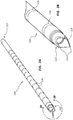
- Figure 1A is a perspective view of a portion of a biopsy needle assembly 105
- Figure 1B is a cross-sectional view of the portion of the biopsy needle assembly 105 of Figure 1A
- the needle assembly 105 comprises an outer tubular member 110 comprising a distal end portion 112, wherein the distal end portion 112 of the outer tubular member 110 is configured to cut or sever a first portion of a tissue sample.
- advancement of the outer tubular member 110 through a tissue sample may core or cut the tissue sample and create a tube-like cut into the tissue, as further discussed below.
- the biopsy needle assembly 105 comprises a cutting member 120, wherein the cutting member 120 is slidably disposed within the outer tubular member 110.
- the cutting member 120 comprises a distal end portion 122, the distal end portion 122 of the cutting member 120 being configured to displace inward to cut or sever a distal end portion, or second portion, of the tissue sample.
- a practitioner such as a medical doctor, may identify a tissue in a patient to be extracted or sampled from the patient ( i.e., for further analysis).
- the outer tubular member 110 can core or cut into the identified tissue sample and create a tube-like cut into the tissue, thus cutting or severing a first portion of the tissue sample.
- the cutting member 120 can be configured to cut or sever a distal end of the tissue sample, or second portion of the tissue sample.
- the tissue sample may be separated from surrounding body tissue and the tissue sample may be extracted or removed from the patient, at least in part, by the biopsy needle assembly 105.
- the cutting or severing of the first portion of the tissue sample may be performed subsequent to the cutting or severing of the second portion of the tissue sample.
- the needle assembly 105 can further comprise a stylet 130, or trocar, wherein the cutting member 120 may be slidably disposed around the stylet 130.
- the stylet 130 can also comprise a distal end portion 132.
- the stylet 130, and/or the distal end portion 132 of the stylet 130 may be configured to facilitate advancement or displacement of the needle assembly 105 through body tissue to a position at or adjacent an identified tissue sample.
- a practitioner can advance the stylet through the skin and/or tissue of a patient to a position at or adjacent to the site of an identified tissue sample.
- the stylet may displace the skin and/or tissue such that a pathway is generated through the skin and/or tissue that may ease advancement of other components of the needle assembly 105 to the position at or adjacent to the site of the tissue sample.
- Figure 2A is a perspective view of the outer tubular member 110 of Figures 1A and 1B
- Figure 2B is a detail view of the distal end portion 112 of the outer tubular member 110 of Figure 2A taken through line 2B
- the outer tubular member 110 comprises the distal end portion 112 and can comprise a proximal end portion 117.
- the outer tubular member 110 and/or the distal end portion 112 of the outer tubular member 110 are configured to sever the first portion of the tissue sample.
- the distal end portion 112 of the outer tubular member 110 may generate or make a tube-shaped cut into or through a body tissue.
- the distal end portion 112 of the outer tubular member 110 of Figures 2A and 2B comprises a plurality of points 114, the points 114 forming a cutting or penetrating edge.
- the cutting or penetrating edge may be sharp such that the outer tubular member 110, and/or the distal end portion 112 of the outer tubular member 110, is configured to cut or sever at least a portion of the tissue sample.
- Other cutting arrangements and mechanisms are also contemplated.
- the distal end portion 112 of the outer tubular member 110 may comprise an annular blade or sharpened edge configured to cut or sever tissue.
- the distal end portion 112 of the outer tubular member 110 comprises three points 114.
- the distal end portion 112 of the outer tubular member 110 may comprise one or two points 114, while in yet other embodiments, the distal end portion 112 of the outer tubular member 110 may comprise four, five, six, or more points 114. Distal end portions 112 of outer tubular members 110 comprising any number of points 114 are within the scope of this disclosure.
- At least a portion of the outer tubular member 110, or the distal end portion 112 of the outer tubular member 110 may be configured to allow or permit the outer tubular member 110 to more easily advance or be displaced through the body tissue. At least a portion of the outer tubular member 110, or the distal end portion 112 of the outer tubular member 110, may also be configured to decrease or limit the effect or impact of displacing or advancing the needle assembly into the body tissue of the patient.
- the outer tubular member 110 can comprise a plurality of indicia 118 configured to indicate to the practitioner a distance that the outer tubular member 110 has advanced into a body tissue (for clarity not all indicia 118 are labeled).
- each indicium 118 may be positioned 1 cm apart; thus, if the practitioner displaces the outer tubular member 110 into a body tissue up to the third indicia 118 from the distal end portion 112 of the outer tubular member 110, it may indicate to the practitioner that approximately 3 cm of the outer tubular member 110 has been displaced into the body tissue.
- the indicia 118 may comprise a plurality of substantially evenly spaced annular lines, marks, or grooves on an outside surface of the outer tubular member 110. In certain embodiments, the indicia 118 may comprise a plurality of tick marks or the indicia may not be evenly spaced. Embodiments of any configuration of indicia are contemplated.
- a portion or portions of at least one of the components of the biopsy needle assembly may also comprise a radiopaque material and/or an echogenic material.
- a radiopaque material (for example, in combination with a fluoroscope) may aid the practitioner in directing or displacing the needle assembly to a desired or predetermined position within the body tissue of the patient. Bismuth, gold, or other radiopaque materials alone, or in combination, may be used.
- An echogenic material (for example, in combination with ultrasound) may analogously aid the practitioner in directing or displacing the needle assembly to a desired or predetermined position within the body tissue of the patient. Surface disruptions such as texturing, grooves, dimples, or a combination of materials may also be used.
- Figure 3A is a perspective view of the cutting member 120 of Figure 1B
- Figure 3B is a detail view of the distal end portion 122 of the cutting member 120 of Figure 3A taken through line 3B.
- the cutting member 120 may comprise a lumen along at least a portion of a length of the cutting member 120.
- the cutting member 120 further comprises the distal end portion 122 and can comprise a proximal end portion 127, the cutting member 120, and/or the distal end portion 122 of the cutting member 120 being configured to cut or sever the distal end portion, or second portion, of the tissue sample, as described above.
- At least a portion of the distal end portion 122 of the cutting member 120 is configured to displace inward to cut or sever the distal end portion, or second portion, of the tissue sample.
- the outer tubular member 110 may generate a tube-like cut into the body tissue, severing the first portion of the tissue sample, and the cutting member 120 may be configured to cut or sever the tissue sample at a distal end of the tissue sample, severing the second portion of the tissue sample, at or adjacent a distal end of the tube-like cut made by the outer tubular member 110.
- the cutting member 120 may be configured to cut or sever the distal end portion, or second portion, of the tissue sample at the same longitudinal position as the distal end of the tube-like cut made by the outer tubular member 110. In other embodiments, the cutting member 120 may be configured to cut or sever the distal end portion, or second portion, of the tissue sample at a position less than 5 mm, less than 4 mm, less than 3 mm, less than 2 mm, or less than 1 mm from the distal end of the tube-like cut made by the outer tubular member 110.
- the cutting member 120 may be configured to cut or sever the distal end portion, or second portion, of the tissue sample at a clinically relevant position from the distal end of the tube-like cut made by the outer tubular member 110.
- the cutting member 120 may also be configured to cut or sever the second portion of the tissue sample at other positions relative to the distal end of the tube-like cut made by the outer tubular member 110.
- the cutting member 120 comprises one or more sectioning elements 124.
- the sectioning elements 124 may be coupled to the cutting member 120.
- the sectioning elements 124 and the cutting member 120 may be integrally formed from a single piece of material.
- at least one of the sectioning elements 124 may comprise a sharp distal portion.
- At least one of the sectioning elements 124 may also comprise at least one sharp lateral edge portion.
- the at least one sharp lateral edge portion may be angled.
- the sectioning elements 124 can be spade- or shovel-shaped.
- Such a configuration of the one or more of the sectioning elements 124 may facilitate the cutting or severing of body tissue by the sectioning elements 124.
- the shape of the sectioning elements 124 may be configured such that the sectioning elements 124 may be simultaneously, or substantially simultaneously, inwardly displaced toward each other to sever the second portion of the tissue sample. Interaction with other components of a biopsy device may be configured to inwardly displace the sectioning elements 124. For example, and as further detailed below in connection with Figures 4A and 4B , interaction between the sectioning elements 124 and one or more portions of the outer tubular member 110 may cause the sectioning elements 124 to displace inwardly.
- At least a portion of at least one of the sectioning elements 124 may be elastically deformable radially inward toward a central axis of the cutting member 120.
- at least a portion of one of the sectioning elements 124, or at least one of the sectioning elements 124 may comprise a super elastic alloy, such as nitinol, for example. Displacement of at least a portion of at least one of the sectioning elements 124 toward the central axis of the cutting member 120 is configured to sever the second portion of the tissue sample.
- a portion of each of the sectioning elements 124 may be configured to displace toward the central axis of the cutting member 120 to sever the second portion of the tissue sample.
- the cutting member 120 may be further configured to sever the second portion of the tissue sample at or adjacent a distal-most point of the distal end portion of the outer tubular member.
- the cutting member 120 may be configured to cut or sever the second portion of the tissue sample at a position less than 5 mm, less than 4 mm, less than 3 mm, less than 2 mm, or less than 1 mm from the distal-most point of the distal end portion of the outer tubular member.
- the cutting member 120 may also be configured to cut or sever the second portion of the tissue sample at the same longitudinal position as the distal-most point of the distal end portion of the outer tubular member.
- the cutting member 120 may also be configured to cut or sever the second portion of the tissue sample at other positions relative to the distal-most point of the distal end portion of the outer tubular member.
- Some biopsy devices may comprise one or more cutting members that are configured to cut or sever a body tissue of a patient.
- a practitioner may advance the one or more cutting members into a body tissue, cutting or severing at least a portion of the tissue along a certain length, which may be termed a stroke length.
- one or more of the cutting members may be configured to cut or sever a distal end of the tissue sample.
- the distal end of the tissue sample may be positioned proximal to a distal end of the stroke length.
- the tissue sample length can be shorter than the stroke length.
- the dead space may comprise tissue that is at least partially severed ( i.e., by the initial advancement of the one or more cutting members into the body tissue) but that is positioned distal to the distal end of the tissue sample, and thus not extracted from the patient upon retraction of the needle assembly and/or the tissue sample from the body tissue.
- the dead space is body tissue that is at least partially cut or severed but that is not part of the tissue sample. Tissue at or adjacent the dead space may be damaged, and as such a practitioner may desire to minimize or avoid generating dead space.
- the structure and/or the form of the one or more cutting members of the biopsy device may be designed to minimize or eliminate a length or an amount of generated dead space.
- embodiments of the needle assembly of the current disclosure can be configured to minimize or eliminate the generation or production of dead space.
- Minimizing or eliminating dead space may increase the precision with which a practitioner can extract a tissue sample and thus limit unwanted trauma to tissue around the sample site.
- a practitioner may identify or locate a tissue sample for removal or extraction from a patient.
- the identified tissue sample may be positioned at or adjacent to a body component, tissue, or organ that the practitioner may desire or need to avoid cutting, piercing, severing, etc.
- the body component may include, but is not limited to, a vessel.
- a biopsy needle assembly that is configured to minimize or eliminate dead space may be utilized in such a circumstance or situation.
- At least a portion of a biopsy needle assembly can be disposed at or adjacent the tissue sample; the needle assembly may sever and/or extract the tissue sample without cutting, piercing, or severing body components, such as vessels, which may be positioned at or adjacent the tissue sample.
- Figures 3C is a perspective view of another embodiment of a cutting member and Figure 3D is a detail view of a distal end portion of the cutting member of Figure 3C taken through line 3D that can, in certain respects, resemble components of the cutting member described in connection with FIGS. 3A and 3B .
- FIGS. 3A and 3B Figures 3C and 3D are identicalous features.
- like features are designated with like reference numerals, with the reference numerals appended with the prime symbol (').
- the distal end portion is designated as "122" in FIGS. 3A and 3B
- an analogous distal end portion is designated as "122'" in FIGS. 3C and 3D .
- Relevant disclosure set forth above regarding similarly identified features thus may not be repeated hereafter.
- FIGS. 3A and 3B may not be shown or identified by a reference numeral in the drawings or specifically discussed in the written description that follows. However, such features may clearly be the same, or substantially the same, as features depicted in other embodiments and/or described with respect to such embodiments. Accordingly, the relevant descriptions of such features apply equally to the features of the cutting member of FIGS. 3C and 3D . Any suitable combination of the features, and variations of the same, described with respect to the cutting member and components illustrated in FIGS. 3A and 3B can be employed with the cutting member and components of FIGS. 3C and 3D , and vice versa. This pattern of disclosure applies equally to further embodiments depicted in subsequent figures and described hereafter.
- Figure 3C is a perspective view of a cutting member 120', analogous to the cutting member 120 of Figure 3A
- Figure 3D is a detail view of a distal end portion 122' of the cutting member 120' of Figure 3C taken through line 3D.
- the cutting member 120' may comprise a lumen along at least a portion of a length of the cutting member 120'.
- the cutting member 120' comprises one or more spiral cuts 140' disposed along at least a portion or portions of the length of the cutting member 120'.
- the cutting member 120' may also comprise a plurality of sectioning elements 124'.
- the spiral cut 140' is disposed along at least a portion of the length of the cutting member 120' at a position proximal to the sectioning elements 124'.
- the cutting member 120' comprises a spiral cut 140' disposed proximal of the one or more sectioning elements 124'.
- the spiral cut 140' may be disposed at a distance sufficiently proximal in relation to the sectioning elements 124' such that the spiral cut 140' does not, or does not substantially, interfere with or damage a tissue sample.
- the cutting member 120' comprises one or more sectioning elements 124' (e.g., two, three, four, five, six, or more sectioning elements 124'). In the illustrated embodiment, the cutting member 120' comprises six sectioning elements 124'. As discussed above, the sectioning elements 124' may be coupled to the cutting member 120'. In some configurations, the sectioning elements 124' and the cutting member 120' may be integrally formed from a single piece of material. In certain embodiments, at least one of the sectioning elements 124' may comprise a sharp distal portion. As depicted in Figures 3C and 3D , the sectioning elements 124' can comprise a pointed or tapered distal portion. At least one of the sectioning elements 124' may also comprise at least one sharp lateral edge portion. In some embodiments, the at least one sharp lateral edge portion may be angled.
- the sectioning elements 124' can comprise a plurality of angled lateral edge portions.
- the lateral edge portions of the section elements 124' may be serrated or notched.
- Such a configuration of the one or more sectioning elements 124' may facilitate the cutting or severing of body tissue by the sectioning elements 124'.
- the shape of the sectioning elements 124' may also be configured such that the sectioning elements 124' may be simultaneously, or substantially simultaneously, inwardly displaced toward each other to sever the second portion of the tissue sample. Interaction with other components of a biopsy device may also be configured to inwardly displace the sectioning elements 124'. For example, and as further detailed below in connection with Figures 4A and 4B , interaction between the sectioning elements 124' and one or more portions of the outer tubular member may cause the sectioning elements 124'to displace inwardly.
- the spiral cut 140' may extend completely through a wall of the cutting member 120'. In some other embodiments, the spiral cut 140' may only extend partially through the wall of the cutting member 120'. For example, the spiral cut 140' may form a groove along a portion of the length of the cutting member 120'. In yet other embodiments, one or more portions of the spiral cut 140' may extend completely through the wall of the cutting member 120' while one or more other portions of the spiral cut 140' may form a groove in the wall of the cutting member 120'.
- disposition of the spiral cut 140' along the cutting member 120' can form a spring, or a spring-like portion, along the cutting member 120'.
- the spiral cut 140' may add or provide compliance or elasticity to the cutting member 120' and/or the biopsy needle assembly.
- the spiral cut 140' may improve or increase tolerances of one or more of the components of the cutting member 120' and/or the biopsy needle assembly. Such improved tolerances may facilitate advancement or displacement of the cutting member 120' and/or the biopsy needle assembly through a body tissue.
- the spiral cut 140' may absorb impact or shock to one or more of the cutting member 120', other components of the biopsy needle assembly, and/or the biopsy needle assembly.
- the spiral cut 140' is configured to compress (i.e., the spiral cut 140' may compress longitudinally, thus shortening the length of the cutting member 120').
- the spiral cut 140' is configured to longitudinally compress in response to relative displacement of the outer tubular member, or another component of the biopsy needle assembly, in relation to the cutting member 120'.
- One or more forces may result in or cause compression of the spiral cut 140'.
- inertia of the cutting member 120' as it is advanced into a body tissue can result in compression of the spiral cut 140'.
- Displacement of the cutting member 120' in relation to the outer tubular member and/or the stylet may also result in compression of the spiral cut 140'.
- friction between an outside surface of the cutting member 120' and an inside surface of the outer tubular member may result in compression of the spiral cut 140'.
- friction between an inside surface of the cutting member 120' and an outside surface of the stylet may also result in compression of the spiral cut 140'.
- force used to advance or displace the distal end portion 122' and/or the sectioning elements 124' of the cutting member 120' over or past the protrusions or annular ring of the outer tubular member can also result in compression of the spiral cut 140'.
- At least a portion of the spiral cut 140' is configured to rotate, upon compression of the spiral cut 140'. Rotation of the spiral cut 140' causes or results in rotation of the sectioning elements 124' around a central axis of the cutting member 120'. This rotation may facilitate uniform, or substantially uniform, severing of the distal end of a tissue sample.
- the spiral cut 140' and/or the sectioning elements 124' may rotate, or be configured to rotate, between 0° and plus or minus 90°. In some embodiments, the spiral cut 140' and/or the sectioning elements 124' may rotate, or be configured to rotate, between 0° and plus or minus 45°; between 0° and plus or minus 30°; between 0° and plus or minus 15°; between 0° and plus or minus 5°; or another suitable degree of rotation.
- rotation of the sectioning elements 124' through a body tissue may form or result in a cleaner or sharper cut in a tissue sample, as rotation of the sectioning elements 124' may sever along a complete, or a substantially complete, circumference of the distal end of the tissue sample.
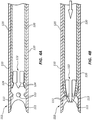
- Figures 4A and 4B depict cross-sectional views of portions of the outer tubular member 110 and the cutting member 120 of Figures 1A and 1B in a first configuration and a second configuration, respectively.
- at least a portion of the distal end portion 122 of the cutting member 120 is positioned proximal to at least a portion of the distal end portion 112 of the outer tubular member 110.
- the outer tubular member 110 may be configured to displace a portion of at least one of the sectioning elements 124 of the cutting member 120 radially inward toward the central axis of the cutting member 120 in response to relative displacement of the outer tubular member 110 with respect to the cutting member 120.
- one or more of the sectioning elements 124 may interact with a portion of the outer tubular member 110 and be displaced inward toward the central axis of the cutting member 120.
- an inside surface 111 of at least a portion of the distal end portion 112 of the outer tubular member 110 can comprise a plurality of inwardly projecting protrusions 113.
- the inside surface 111 of at least a portion of the distal end portion 112 of the outer tubular member 110 may comprise one or more inwardly projecting protrusions 113.
- the protrusions 113 may be configured to at least partially displace a portion of at least one of the sectioning elements 124 inward toward the central axis of the cutting member 120 when the cutting member 120 is displaced distally relative to the outer tubular member 110, as indicated by the arrow ( Figure 4B ).
- the distal end portion 122 of the cutting member 120 is positioned distal to at least a portion of the distal end portion 112 of the cutting member 110.
- the protrusions 113 can act to displace at least a portion of each of the sectioning elements 124 toward the central axis of the cutting member 120 when the cutting member 120 is displaced distally relative to the outer tubular member 110.
- the outer tubular member 110 may comprise a raised, annular surface or ridge, such as a circular ridge extending completely around the inside diameter of the outer tubular member 110.
- raised arc-shaped segments may also be utilized.
- the raised, annular surface or arc-shaped segments may be configured to displace a portion of at least one of the sectioning elements 124 inward toward the central axis of the cutting member 120 when the cutting member 120 is displaced distally relative to the outer tubular member 110.
- the raised, annular surface may also be configured to inwardly displace at least a portion of the sectioning elements 124 of the cutting member 120 to cut or sever the second portion of the tissue sample regardless of the relative rotations of the outer tubular member 110 and the cutting member 120 to each other.
- distal displacement of the cutting member 120 relative to the outer tubular member 110 may cause at least a portion of at least one of the sectioning elements 124 of the cutting member 120 to interact with a component of the outer tubular member 110 (including, but not limited to, the inwardly projecting protrusions 113, raised annular surface, or raised arc-shaped segments), displacing inward the at least one sectioning element 124 to sever at least a portion of the distal end, or second portion, of the tissue sample.
- a component of the outer tubular member 110 including, but not limited to, the inwardly projecting protrusions 113, raised annular surface, or raised arc-shaped segments
- At least a portion of the outer tubular member 110, or the distal end portion 112 of the outer tubular member 110 may be configured to overlap one or more of the sectioning elements 124 of the cutting member 120, thus generating an overlapping arrangement.
- the one or more sectioning elements 124 may be fully or substantially disposed within the outer tubular member 110.
- the overlapping arrangement of the outer tubular member 110 and the cutting member 120 can add rigidity and structure to at least a portion of the needle assembly.
- the overlapping arrangement may reinforce the sectioning elements 124 and may reduce deformation of the sectioning elements 124 during use.
- the outer tubular member 110 disposed around the sectioning elements 124, may prevent outward deformation of the sectioning elements 124 as the outer tubular member 110 and cutting member 120 are advanced through body tissue.
- disposition of the cutting member 120 between the stylet and the outer tubular member 110 may tend to secure the sectioning elements 124, minimizing deformation thereof, as the needle assembly 105 is advanced through body tissue.
- the overlapping arrangement may also facilitate entry of body tissue into at least a portion of a lumen of the cutting member 120 without bending or otherwise damaging the one or more sectioning elements 124 and/or the cutting member 120.
- the outer tubular member 110 may sever the first cylindrical portion of a tissue sample as the outer tubular member 110 is actuated.
- the cutting member 120 may generally follow the tube-like cut, or annular cut, created by the outer tubular member 110 as the cutting member 120 is initially advanced, prior to severing the second portion, or distal end, of the tissue sample.
- the relative position of the outer tubular member 110 with respect to the cutting member 120 may facilitate entry of the tissue sample into the lumen of the cutting member 120 without the tissue sample catching and prematurely deforming the sectioning elements 124.
- the tube-like path, or annular path, created by the tubular member 110 may also minimize or prevent body tissue from being blocked and/or damaged by the one or more sectioning elements 124 and/or the cutting member 120 when the body tissue enters the lumen of the cutting member 120.
- the outer tubular member 110 may be configured to generate a tube-like cut into a body tissue.
- the overlapping arrangement may be configured such that the outer tubular member 110 directs the one or more sectioning elements 124 and/or the cutting member 120 into the body tissue at the site of the tube-like cut (for example, when a handle or actuator displaces or deflects the cutting member 120 into the body tissue).
- Such an arrangement may minimize or prevent the one or more sectioning elements 124 and/or the cutting member 120 from damaging the body tissue at or adjacent the tube-like cut, for example by minimizing the likelihood the tissue sample will be scratched or otherwise damaged as it passes the sectioning elements 124 and moves into the lumen of the cutting member 120.
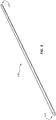
- Figure 5 is a perspective view of the stylet 130, or trocar, of the needle assembly 105 of Figure 1A .
- the cutting member as described above, may be slidably disposed around the stylet 130.
- the stylet 130 may be fixed with respect to an actuator or handle as described below in connection with Figure 6 .
- the stylet 130 comprises the distal end portion 132 and a proximal end portion 137.
- the distal end portion 132 as illustrated, can be substantially sharp.
- the stylet 130, and/or the distal end portion 132 of the stylet 130 may be configured to facilitate movement of the needle assembly through body tissue.
- a practitioner or user can advance the stylet 130 through the skin and/or tissue of a patient to a position at or adjacent to the site of an identified tissue sample.
- the stylet 130 may displace the skin and/or tissue such that a pathway is generated through the skin and/or tissue that may ease advancement of other components of the needle assembly to the position at or adjacent to the site of the tissue sample.
- FIG 6 is a perspective view of a tissue biopsy device 100 comprising the needle assembly 105 of Figures 1A and 1B .
- the tissue biopsy device 100 can comprise a needle assembly 105 operatively coupled to a handle 102, or actuator.
- a handle 102 or actuator.
- at least a portion of at least one of the proximal end portions of the outer tubular member 110, the cutting member, and/or the stylet 130 may be operatively coupled to the handle 102.
- the handle 102 may be configured to actuate at least one of the outer tubular member 110, the cutting member, and/or the stylet 130 to cut or sever the tissue sample from the body of a patient.
- the handle 102 may be configured to actuate at least the outer tubular member 110 and the cutting member to cut or sever the tissue sample from the body.
- the handle 102 may also be configured to retract the needle assembly 105 from the body and/or to extract the tissue sample from the body of a patient. It is within the scope of this disclosure to couple embodiments of the biopsy needle assembly, as described herein, to any type of handle or actuator.
- a handle or actuator can have springs and can displace components of the needle assembly 105 relative to each other. A series of steps or displacements of the components of the tissue biopsy device 100 can be effectuated in response to a single input or trigger by a practitioner.
- Various handles or actuators may be used with the biopsy needle assemblies disclosed herein. For example, United States Patent Application No. 14/157935, filed on January 17, 2014 and titled "Impact Biopsy Device and Method of Use," which is hereby incorporated by reference in its entirety, discloses handles and actuators that may be used in connection with the biopsy needle assemblies disclosed here.
- an exemplary tissue biopsy device may comprise a first elongate member configured to be advanced into a body tissue, for example, an elongate member analogous to the stylet 130 of Figures 1A and 1B .
- the tissue biopsy device may further comprise a second elongate member, wherein the second elongate member is disposed around the first elongate member, and wherein the second elongate member is configured to sever a first portion of a tissue sample, for example, an elongate member analogous to the outer tubular member 110 of Figures 1A and 1B .
- the tissue biopsy device may comprise a third elongate member, wherein the third elongate member may be movably disposed within the second elongate member and around the first elongate member, and wherein the third elongate member is configured to sever a second portion of the tissue sample at or adjacent a distal-most point of a distal end portion of the second elongate member, for example, an elongate member analogous to the cutting member 120 of Figure 1B .
- the third elongate member may be configured to cut or sever the second portion of the tissue sample at the same longitudinal position as the distal-most point of the distal end portion of the second elongate member.
- the third elongate member may be configured to cut or sever the second portion of the tissue sample at a position less than 5 mm, less than 4 mm, less than 3 mm, less than 2 mm, or less than 1 mm from the distal-most point of the distal end portion of the second elongate member.
- the third elongate member may also be configured to cut or sever the second portion of the tissue sample at other positions relative to the distal-most point of the distal end portion of the second elongate member.
- the tissue biopsy device may comprise an actuator, for example, an actuator analogous to the handle 102 of Figure 6 .
- the actuator may be configured to displace or deflect at least one of the second elongate member and the third elongate member such that the tissue sample is severed.
- the actuator may also be configured to retract each of the first elongate member, the second elongate member, the third elongate member, and/or the tissue sample from the body of a patient.
- a distal end portion of the third elongate member is configured to contract toward a central axis of the third elongate member to sever the second portion of the tissue sample.
- the distal end portion of the second elongate member may be configured to deflect the contraction of the distal end portion of the third elongate member.
- the third elongate member can also be configured to extract the severed tissue sample from the body tissue and/or the patient.
- Figures 7A-7C are schematic in nature.
- the figures show the functional and operational relationships of a portion of the biopsy needle assembly 105 upon use in a patient, but the figures are not intended to indicate any particular structure or spatial disposition of any tissue, organ, body component, or group of body components in the patient.
- the schematic representations herein may be drawn to show internal tissues and/or organs of the patient without explicitly designating cross-sections or cutaways of the tissues and/or organs.
- a body tissue may be schematically shown with the biopsy needle assembly disposed therein without indicating a cross-section portion or cutaway of a portion of the body tissue.
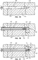
- Figure 7A is a schematic representation of a side view of a portion of the needle assembly 105 of Figure 1A in a first configuration.
- Figures 7B and 7C are schematic representations of cross-sectional views of the portion of the needle assembly 105 of Figure 7A in a second configuration and a third configuration, respectively. For clarity, the stylet 130 of Figure 1A is not shown in Figures 7B and 7C .
- Figure 7A illustrates at least the outer tubular member 110 and the stylet 130 of the needle assembly 105 advanced into a body tissue 150, as shown by the arrow.
- a practitioner may determine a tissue sample to obtain.
- the distal end portion 132 of the stylet 130 may be disposed to a position at or adjacent a proximal end portion of the predetermined tissue sample.
- displacement of the outer tubular member 110 with respect to the cutting member 120 and the body tissue 150 is depicted, as shown by the arrows. As depicted, such displacement of the outer tubular member 110, and the distal end 112 of the outer tubular member 110, can sever a first portion 156 of a tissue sample 154.
- the distal end portion 112 of the outer tubular member 110 can be displaced distally relative to the distal end portion of the stylet (not shown), such that the distal end portion 112 of the outer tubular member 110 is extended a distance, or stroke length, into the body tissue 150 relative to the stylet.
- the length D 3 as identified in Figure 7B , represents the stroke length, as described above.
- the distal end portion 122 of the cutting member 120 may be displaced, as shown by the arrow, to a position at or adjacent the distal end portion 112 of the outer tubular member 110. Displacement of the cutting member 120 with respect to the outer tubular member 110 and the body tissue 150 may result in at least a portion of the cutting member 120 severing a second portion 158 of the tissue sample 154 at or adjacent a distal-most point of the distal end portion 112 of the outer tubular member 110.
- the cutting member 120 may be configured to cut or sever the second portion 158 of the tissue sample 154 at a position less than 5 mm, less than 4 mm, less than 3 mm, less than 2 mm, or less than 1 mm from the distal-most point of the distal end portion 112 of the outer tubular member 110.
- the cutting member 120 may also be configured to cut or sever the second portion 158 of the tissue sample 154 at the same longitudinal position as the distal-most point of the distal end portion 112 of the outer tubular member 110.
- the cutting member 120 may also be configured to cut or sever the second portion 158 of the tissue sample 154 at other positions relative to the distal-most point of the distal end portion 112 of the outer tubular member 110.
- the length D 1 represents the length of the severed tissue sample 154, or tissue sample length.
- the length D 2 represents the length of the dead space, as described above.
- the configuration of the distal end portion 122 of the cutting member 120 with respect to the distal end portion 112 of the outer tubular member 110 may be such that the distal end of the tissue sample 154 is severed at or adjacent the distal end portion 112 of the outer tubular member 110. Such a configuration may minimize or eliminate the length of the dead space.
- the distal end portion 122 of the cutting member 120 can engage with at least a portion of the distal end portion 112 of the outer tubular member 110 such that the distal end portion 122 of the cutting member 120 is configured to sever the second portion 158 of the tissue sample 154.
- severing the second portion 158 of the tissue sample 154 may comprise displacing at least a portion of the distal end portion 122 of the cutting member 120 toward a central axis of the cutting member 120.
- the tissue sample length D 1 and the dead space length D 2 are equal, or approximately equal, to the stroke length D 3 (i.e., D 1 + D 2 ⁇ D 3 ).
- the needle assembly is configured to minimize or eliminate the length of the dead space D 2 .
- the tissue sample length D 1 may be equal, or approximately equal, to the stroke length D 3 ( i.e., D 1 ⁇ D 3 ).
- Such embodiments of biopsy needle assemblies, as described above, may be configured for use when it may be undesirable to cut, pierce, or sever a body component, tissue, or sample at or adjacent a predetermined tissue sample or simply to minimize trauma to surrounding tissue during a biopsy.
- actuation of the outer tubular member 110 and/or the cutting member 120 may be effectuated by a handle or actuator, such as handle 102 of Figure 6 .
- displacement of the outer tubular member 110 may occur prior to the displacement of the cutting member 120.
- displacement of the outer tubular member 110 and the cutting member 120 may occur substantially simultaneously.
- the position of the stylet may remain substantially stationary during the displacement of each of the outer tubular member 110 and the cutting member 120.
- Other timing and/or sequences of the displacement of each of the outer tubular member 110 and the cutting member 120 are also contemplated.
- each of the stylet, the outer tubular member 110, and the cutting member 120 may be retracted from the body tissue 150 of the patient such that the tissue sample 154 can be extracted from the body tissue 150.
- relative positions of each of the stylet, the outer tubular member 110, and the cutting member 120 may be substantially maintained upon the retraction of the each of the stylet, the outer tubular member 110, and the cutting member 120 from the body tissue 150.
Claims (12)
- Ensemble aiguille de biopsie (105) configuré pour son utilisation avec un dispositif de biopsie tissulaire, l'ensemble aiguille de biopsie (105) comprenant :un élément tubulaire externe (110) comprenant une partie d'extrémité distale (112) configurée pour couper une première partie d'un échantillon tissulaire ; etun élément de coupe (120, 120') monté coulissant dans l'élément tubulaire externe (110), dans lequel l'élément de coupe (120, 120') comporte une partie d'extrémité distale (122, 122'), et dans lequel la partie d'extrémité distale (122, 122') de l'élément de coupe (120, 120') est configurée pour se déplacer vers l'intérieur afin de couper une deuxième partie de l'échantillon tissulaire,dans lequel la partie d'extrémité distale (122, 122') de l'élément de coupe (120, 120') comprend en outre un ou plusieurs éléments de sectionnement (124, 124'), et dans lequel le déplacement d'une partie d'au moins un des éléments de sectionnement (124, 124') vers un axe central de l'élément de coupe (120, 120') est configuré pour couper la deuxième partie de l'échantillon tissulaire,caractérisé en ce que,l'élément de coupe (120, 120') comprend en outre une découpe en spirale (140') disposée à proximité des un ou plusieurs éléments de sectionnement (124, 124'), dans lequel la découpe en spirale (140') est configurée pour se compresser longitudinalement en réponse au déplacement relatif de l'élément tubulaire externe (110) par rapport à l'élément de coupe (120, 120'),la compression de la découpe en spirale (140') est configurée pour faire tourner les un ou plusieurs éléments de sectionnement (124, 124') autour de l'axe central de l'élément de coupe (120, 120').
- Ensemble aiguille de biopsie (105) selon la revendication 1, dans lequel l'élément de coupe (120, 120') est configuré pour couper la deuxième partie de l'échantillon tissulaire au niveau d'un ou au voisinage d'un point le plus distal de la partie d'extrémité distale (112) de l'élément tubulaire externe (110).
- Ensemble aiguille de biopsie (105) selon l'une quelconque des revendications 1-2, dans lequel l'élément de coupe (120, 120') est configuré pour couper la deuxième partie de l'échantillon tissulaire à une position de moins de 3 mm d'un point le plus distal de la partie d'extrémité distale (112) de l'élément tubulaire externe (110).
- Ensemble aiguille de biopsie (105) selon l'une quelconque des revendications 1-3, dans lequel l'élément tubulaire externe (110) est configuré pour déplacer la partie de l'au moins un des éléments de sectionnement (124, 124') vers l'axe central de l'élément de coupe (120, 120') en réponse au déplacement relatif de l'élément tubulaire externe (110) par rapport à l'élément de coupe (120, 120').
- Ensemble aiguille de biopsie (105) selon la revendication 4, dans lequel une surface intérieure de la partie d'extrémité distale (112) de l'élément tubulaire externe (110) comprend une ou plusieurs protubérances s'étendant en saillie vers l'intérieur (113), et dans lequel les une ou plusieurs protubérances (113) sont configurées pour déplacer la partie de l'au moins un des éléments de sectionnement (124, 124') vers l'intérieur vers l'axe central de l'élément de coupe (120, 120') lorsque l'élément de coupe (120, 120') est déplacé de manière distale par rapport à l'élément tubulaire externe (110).
- Ensemble aiguille de biopsie (105) selon la revendication 4, dans lequel une surface intérieure (111) de la partie d'extrémité distale (112) de l'élément tubulaire externe (110) comprend une surface annulaire surélevée, et dans lequel la surface annulaire surélevée est configurée pour déplacer la partie de l'au moins un des éléments de sectionnement (124, 124') vers l'intérieur vers l'axe central de l'élément de coupe (120, 120') lorsque l'élément de coupe (120, 120') est déplacé de manière distale par rapport à l'élément tubulaire externe (110).
- Ensemble aiguille de biopsie (105) selon l'une quelconque des revendications 1-6, dans lequel au moins un des éléments de sectionnement (124, 124') comprend une partie de bord distal tranchant.
- Ensemble aiguille de biopsie (105) selon l'une quelconque des revendications 1-7, dans lequel une partie d'au moins un des éléments de sectionnement (124, 124') est élastiquement déformable vers l'intérieur en direction de l'axe central de l'élément de coupe (120, 120').
- Ensemble aiguille de biopsie (105) selon l'une quelconque des revendications 1-8, comprenant en outre un stylet (130) disposé dans l'élément de coupe (120, 120'), dans lequel le stylet (130) comprend une partie d'extrémité distale configurée pour faciliter la progression de l'ensemble aiguille de biopsie (105) à travers un tissu corporel.
- Ensemble aiguille de biopsie (105) selon l'une quelconque des revendications 1-9, comprenant en outre un manche (102) configuré pour actionner au moins l'élément tubulaire externe (110) et l'élément de coupe (120, 120') pour couper l'échantillon tissulaire du tissu corporel.
- Ensemble aiguille de biopsie (105) selon l'une quelconque des revendications 1-10, dans lequel une partie d'extrémité distale (112) de l'élément de coupe (120, 120') est configurée pour se contracter vers un axe central de l'élément de coupe (120, 120') pour couper la deuxième partie de l'échantillon tissulaire.
- Ensemble aiguille de biopsie (105) selon l'une quelconque des revendications 1-11, dans lequel l'élément de coupe (120, 120') est en outre configuré pour extraire l'échantillon tissulaire coupé du tissu corporel.
Applications Claiming Priority (2)
| Application Number | Priority Date | Filing Date | Title |
|---|---|---|---|
| US201461928865P | 2014-01-17 | 2014-01-17 | |
| PCT/US2015/011746 WO2015109178A1 (fr) | 2014-01-17 | 2015-01-16 | Ensemble aiguille de biopsie coupée net et procédé d'utilisation |
Publications (3)
| Publication Number | Publication Date |
|---|---|
| EP3094262A1 EP3094262A1 (fr) | 2016-11-23 |
| EP3094262A4 EP3094262A4 (fr) | 2017-09-13 |
| EP3094262B1 true EP3094262B1 (fr) | 2019-07-03 |
Family
ID=53543477
Family Applications (1)
| Application Number | Title | Priority Date | Filing Date |
|---|---|---|---|
| EP15737182.4A Active EP3094262B1 (fr) | 2014-01-17 | 2015-01-16 | Ensemble aiguille de biopsie coupée net |
Country Status (5)
| Country | Link |
|---|---|
| US (1) | US10568611B2 (fr) |
| EP (1) | EP3094262B1 (fr) |
| DK (1) | DK3094262T3 (fr) |
| ES (1) | ES2746123T3 (fr) |
| WO (1) | WO2015109178A1 (fr) |
Families Citing this family (50)
| Publication number | Priority date | Publication date | Assignee | Title |
|---|---|---|---|---|
| US9232959B2 (en) | 2007-01-02 | 2016-01-12 | Aquabeam, Llc | Multi fluid tissue resection methods and devices |
| ES2769535T3 (es) | 2008-03-06 | 2020-06-26 | Aquabeam Llc | Ablación de tejido y cauterización con energía óptica transportada en una corriente de fluido |
| US20120191083A1 (en) | 2011-01-20 | 2012-07-26 | Hansen Medical, Inc. | System and method for endoluminal and translumenal therapy |
| ES2687817T3 (es) | 2012-02-29 | 2018-10-29 | Procept Biorobotics Corporation | Resección y tratamiento de tejido guiado por imagen automatizada |
| RU2648028C2 (ru) | 2012-12-19 | 2018-03-21 | Мерит Медикал Системз, Инк. | Устройство для биопсии и способ применения |
| US10231867B2 (en) | 2013-01-18 | 2019-03-19 | Auris Health, Inc. | Method, apparatus and system for a water jet |
| US9392998B2 (en) | 2013-01-18 | 2016-07-19 | Merit Medical Systems, Inc. | Impact biopsy device and method of use |
| WO2014201165A1 (fr) | 2013-06-11 | 2014-12-18 | Auris Surgical Robotics, Inc. | Système pour une chirurgie de cataracte assistée par robot |
| US10426661B2 (en) | 2013-08-13 | 2019-10-01 | Auris Health, Inc. | Method and apparatus for laser assisted cataract surgery |
| ES2746123T3 (es) | 2014-01-17 | 2020-03-04 | Merit Medical Systems Inc | Montaje de aguja para biopsias de corte enrasado |
| US11191938B2 (en) | 2014-01-21 | 2021-12-07 | Merit Medical Systems, Inc. | Introducer sheath and methods |
| JP6777642B2 (ja) | 2015-02-26 | 2020-10-28 | メリット・メディカル・システムズ・インコーポレイテッドMerit Medical Systems,Inc. | 層状医療器具及び方法 |
| BR112017018895B1 (pt) | 2015-03-04 | 2023-05-16 | Merit Medical Systems, Inc | Dispositivo para biópsia de tecido |
| US20160287279A1 (en) | 2015-04-01 | 2016-10-06 | Auris Surgical Robotics, Inc. | Microsurgical tool for robotic applications |
| US9949749B2 (en) | 2015-10-30 | 2018-04-24 | Auris Surgical Robotics, Inc. | Object capture with a basket |
| US9955986B2 (en) | 2015-10-30 | 2018-05-01 | Auris Surgical Robotics, Inc. | Basket apparatus |
| US10639108B2 (en) | 2015-10-30 | 2020-05-05 | Auris Health, Inc. | Process for percutaneous operations |
| JP6419099B2 (ja) * | 2016-01-20 | 2018-11-07 | 日本ライフライン株式会社 | 焼灼用針装置、高周波焼灼治療システムおよび化学焼灼治療システム |
| USD837375S1 (en) | 2016-12-05 | 2019-01-01 | Argon Medical Devices, Inc. | Biopsy device handle |
| US10709429B2 (en) | 2016-12-05 | 2020-07-14 | Argon Medical Devices Inc. | Biopsy device handle |
| US10820893B2 (en) | 2017-02-15 | 2020-11-03 | Cook Medical Technologies Llc | Endoscopic tri-point biopsy needle |
| JP7159192B2 (ja) | 2017-03-28 | 2022-10-24 | オーリス ヘルス インコーポレイテッド | シャフト作動ハンドル |
| KR20230106716A (ko) | 2017-04-07 | 2023-07-13 | 아우리스 헬스, 인코포레이티드 | 환자 삽입기(Introducer) 정렬 |
| US10285574B2 (en) | 2017-04-07 | 2019-05-14 | Auris Health, Inc. | Superelastic medical instrument |
| US20180317895A1 (en) | 2017-05-05 | 2018-11-08 | Hoya Corporation | Endoscopic biopsy needle tip and methods of use |
| WO2018213324A1 (fr) | 2017-05-19 | 2018-11-22 | Merit Medical Systems, Inc. | Dispositif d'aiguille de biopsie semi-automatique et procédés d'utilisation |
| US11160540B2 (en) * | 2017-09-28 | 2021-11-02 | Merit Medical Systems, Inc. | Biopsy needle sample retention system |
| EP3813714A4 (fr) | 2018-06-07 | 2022-02-09 | Auris Health, Inc. | Systèmes médicaux robotisés à instruments à force élevée |
| JP7391886B2 (ja) | 2018-06-28 | 2023-12-05 | オーリス ヘルス インコーポレイテッド | 滑車共有を組み込んだ医療システム |
| US11452537B2 (en) * | 2018-07-19 | 2022-09-27 | Boston Scientific Scimed, Inc. | Medical devices and related methods |
| CN112566584A (zh) | 2018-08-15 | 2021-03-26 | 奥瑞斯健康公司 | 用于组织烧灼的医疗器械 |
| US10639114B2 (en) | 2018-08-17 | 2020-05-05 | Auris Health, Inc. | Bipolar medical instrument |
| CN112770689A (zh) | 2018-09-26 | 2021-05-07 | 奥瑞斯健康公司 | 用于抽吸和冲洗的系统和器械 |
| US11576738B2 (en) | 2018-10-08 | 2023-02-14 | Auris Health, Inc. | Systems and instruments for tissue sealing |
| US11950863B2 (en) | 2018-12-20 | 2024-04-09 | Auris Health, Inc | Shielding for wristed instruments |
| EP3883492A4 (fr) | 2019-01-25 | 2022-11-30 | Auris Health, Inc. | Dispositif de scellement de vaisseaux ayant des capacités de chauffage et de refroidissement |
| WO2020197625A1 (fr) | 2019-03-25 | 2020-10-01 | Auris Health, Inc. | Systèmes et procédés d'agrafage médical |
| US11369386B2 (en) | 2019-06-27 | 2022-06-28 | Auris Health, Inc. | Systems and methods for a medical clip applier |
| WO2020263949A1 (fr) | 2019-06-28 | 2020-12-30 | Auris Health, Inc. | Instruments médicaux comprenant des poignets dotés de surfaces de réorientation hybrides |
| US11896330B2 (en) | 2019-08-15 | 2024-02-13 | Auris Health, Inc. | Robotic medical system having multiple medical instruments |
| US10959792B1 (en) | 2019-09-26 | 2021-03-30 | Auris Health, Inc. | Systems and methods for collision detection and avoidance |
| WO2021064536A1 (fr) | 2019-09-30 | 2021-04-08 | Auris Health, Inc. | Instrument médical avec cabestan |
| US11737835B2 (en) | 2019-10-29 | 2023-08-29 | Auris Health, Inc. | Braid-reinforced insulation sheath |
| CN114364326A (zh) * | 2019-11-20 | 2022-04-15 | 波士顿科学国际有限公司 | 针活检装置 |
| WO2021137104A1 (fr) | 2019-12-31 | 2021-07-08 | Auris Health, Inc. | Système de poulie dynamique |
| WO2021137071A1 (fr) | 2019-12-31 | 2021-07-08 | Auris Health, Inc. | Mode d'entraînement de panier avancé |
| EP4171427A1 (fr) | 2020-06-29 | 2023-05-03 | Auris Health, Inc. | Systèmes et procédés de détection de contact entre une liaison et un objet externe |
| US11357586B2 (en) | 2020-06-30 | 2022-06-14 | Auris Health, Inc. | Systems and methods for saturated robotic movement |
| CN115734765A (zh) | 2020-06-30 | 2023-03-03 | 奥瑞斯健康公司 | 具有碰撞接近度指示器的机器人医疗系统 |
| US11278266B2 (en) * | 2020-07-01 | 2022-03-22 | Verix Health, Inc. | Lung access device |
Family Cites Families (85)
| Publication number | Priority date | Publication date | Assignee | Title |
|---|---|---|---|---|
| DD120119A1 (fr) | 1975-07-01 | 1976-06-05 | ||
| US4785826A (en) * | 1987-03-02 | 1988-11-22 | Ward John L | Biopsy instrument |
| US4946445A (en) | 1988-09-06 | 1990-08-07 | Lynn Lawrence A | Intravenous line coupling device |
| US5632746A (en) | 1989-08-16 | 1997-05-27 | Medtronic, Inc. | Device or apparatus for manipulating matter |
| US5172702A (en) | 1989-11-24 | 1992-12-22 | Medical Device Technologies, Inc. | Disposable spring-loaded soft tissue biopsy apparatus |
| US5336191A (en) | 1992-08-13 | 1994-08-09 | Dlp, Incorporated | Surgical needle assembly |
| US5368574A (en) | 1992-10-01 | 1994-11-29 | Ethicon, Inc. | Percutaneous catheter introducer |
| US6126617A (en) | 1995-01-26 | 2000-10-03 | Ascendia Ab | Impact-damped biopsy instrument |
| US5655542A (en) | 1995-01-26 | 1997-08-12 | Weilandt; Anders | Instrument and apparatus for biopsy and a method thereof |
| US5800389A (en) | 1996-02-09 | 1998-09-01 | Emx, Inc. | Biopsy device |
| US5842999A (en) | 1996-07-31 | 1998-12-01 | C.R. Bard, Inc. | Automated tissue sampling device |
| US6340356B1 (en) | 1997-09-23 | 2002-01-22 | NAVIA JOSé ANTONIO | Intraluminal catheter with expandable tubular open-walled element |
| SE9800738D0 (sv) | 1998-03-06 | 1998-03-06 | Ascendia Ab | Slagdämpat biopsiinstrument |
| USD418223S (en) | 1998-06-05 | 1999-12-28 | Eclipse Surgical Technologies, Inc. | Hand piece for surgical and biopsy procedures |
| US6086543A (en) | 1998-06-24 | 2000-07-11 | Rubicor Medical, Inc. | Fine needle and core biopsy devices and methods |
| US7517348B2 (en) | 1998-09-03 | 2009-04-14 | Rubicor Medical, Inc. | Devices and methods for performing procedures on a breast |
| USD428150S (en) | 1999-02-23 | 2000-07-11 | Lifescan, Inc. | Lancing device |
| US6146338A (en) | 1999-04-23 | 2000-11-14 | Medtronic, Inc. | Apparatus for deflecting a catheter or lead |
| EP1196214B1 (fr) * | 1999-06-22 | 2008-08-20 | Ernesto E. Blanco | Trocart de securite pourvu de protections de tete de coupe et d'un deflecteur a jet de gaz dans les tissus. |
| SE0002281D0 (sv) | 2000-06-16 | 2000-06-16 | Ascendia Ab | Flergångs biopsianordning och motsvarande engångs biopsiinstrument |
| ATE347309T1 (de) | 2000-07-29 | 2006-12-15 | Worldwide Medical Technologies | Werkzeug zum herausziehen von knochenmark |
| US6656195B2 (en) * | 2000-09-22 | 2003-12-02 | Medtronic Xomed, Inc. | Flexible inner tubular members and rotary tissue cutting instruments having flexible inner tubular members |
| USD460185S1 (en) | 2000-10-26 | 2002-07-09 | Grieshaber & Co. Ag Schaffhausen | Ophthalmologic surgical instrument |
| US6758824B1 (en) | 2000-11-06 | 2004-07-06 | Suros Surgical Systems, Inc. | Biopsy apparatus |
| US6419641B1 (en) | 2000-11-28 | 2002-07-16 | Promex, Llc | Flexible tip medical instrument |
| US6488662B2 (en) | 2000-12-19 | 2002-12-03 | Laksen Sirimanne | Percutaneous catheter assembly |
| USD457955S1 (en) | 2001-03-29 | 2002-05-28 | Annex Medical, Inc. | Handle |
| US6860463B2 (en) | 2001-12-04 | 2005-03-01 | William A. Cook Australia Pty. Ltd. | Access valve |
| US8137317B2 (en) | 2002-03-15 | 2012-03-20 | Oscor Inc. | Locking vascular introducer assembly with adjustable hemostatic seal |
| US20040054377A1 (en) | 2002-07-12 | 2004-03-18 | Foster Thomas L. | Flexible cannula |
| AU2003257087B2 (en) | 2002-08-01 | 2009-01-08 | James E. Selis | Biopsy devices |
| US20080161720A1 (en) | 2002-10-07 | 2008-07-03 | Nicoson Zachary R | Registration system |
| AU2003284115A1 (en) | 2002-10-10 | 2004-05-04 | Becton, Dickinson And Company | Method of delivering local anesthesia |
| US7247160B2 (en) | 2002-12-30 | 2007-07-24 | Calypso Medical Technologies, Inc. | Apparatuses and methods for percutaneously implanting objects in patients |
| US20040133124A1 (en) | 2003-01-06 | 2004-07-08 | Cook Incorporated. | Flexible biopsy needle |
| USD490152S1 (en) | 2003-02-28 | 2004-05-18 | Glaukos Corporation | Surgical handpiece |
| DE20305093U1 (de) | 2003-03-29 | 2003-09-11 | Heske Norbert F | Koaxialkanüle mit Dichtelement |
| US7311673B2 (en) | 2003-04-24 | 2007-12-25 | Acueity, Inc. | Biopsy device |
| US7608048B2 (en) | 2003-08-28 | 2009-10-27 | Goldenberg Alec S | Rotating soft tissue biopsy needle |
| US7988642B2 (en) | 2003-10-14 | 2011-08-02 | Suros Surgical Systems, Inc. | Vacuum assisted biopsy device |
| US20050125017A1 (en) | 2003-12-05 | 2005-06-09 | Paul Kudrna | Lancet device and method |
| EP1734856A2 (fr) | 2004-03-11 | 2006-12-27 | Medrad, Inc. | Dispositifs medicaux assistes par energie, systemes et procedes |
| GB0417400D0 (en) | 2004-08-05 | 2004-09-08 | Univ Dundee | Biopsy apparatus and method |
| TWI369970B (en) | 2004-10-20 | 2012-08-11 | Beaver Visitec Int Us Inc | Surgical knife safety handle having user operable lock |
| US20060211992A1 (en) | 2004-11-18 | 2006-09-21 | Laparoscopic Partners Llc | Surgical instrument seal assembly and triple lead thread |
| DE602004013450T2 (de) | 2004-11-25 | 2009-06-04 | Carro, Luigi, Rudiano | Greifglied für biomezidinische Nadel |
| US7470237B2 (en) | 2005-01-10 | 2008-12-30 | Ethicon Endo-Surgery, Inc. | Biopsy instrument with improved needle penetration |
| US20080300507A1 (en) | 2005-01-28 | 2008-12-04 | The General Hospital Corporation | Biopsy Needle |
| US8002818B2 (en) | 2005-02-25 | 2011-08-23 | Abbott Laboratories Vascular Enterprises Limited | Modular vascular prosthesis having axially variable properties and improved flexibility and methods of use |
| US20060224082A1 (en) * | 2005-04-05 | 2006-10-05 | Vetter James W | Methods and devices for removing tissue from a patient and placing a marker in the patient |
| US7662729B2 (en) | 2005-04-28 | 2010-02-16 | Micron Technology, Inc. | Atomic layer deposition of a ruthenium layer to a lanthanide oxide dielectric layer |
| US20070078472A1 (en) | 2005-10-04 | 2007-04-05 | Gajendra Singh | Gajendra Safe Surgical Knife - AKA- GSS knife |
| WO2007051509A1 (fr) | 2005-11-07 | 2007-05-10 | Janssens Jaak Ph | Ensemble aiguille de biopsie et dispositif de prelevement de tissu |
| US20070142744A1 (en) | 2005-12-16 | 2007-06-21 | Provencher Kevin M | Tissue sample needle and method of using same |
| USD598543S1 (en) | 2006-06-13 | 2009-08-18 | Angiomed Gmbh & Co. Medizintechnik Kg | Handle for a medical delivery device |
| US20080051707A1 (en) | 2006-08-25 | 2008-02-28 | Phan Christopher U | Apparatus and methods for use of expandable members in surgical applications |
| AU311984S (en) | 2006-08-31 | 2006-12-14 | Thoratec Corp | Surgical tool |
| JP4998165B2 (ja) | 2006-09-19 | 2012-08-15 | 株式会社ジェイ・エム・エス | 医療用針装置 |
| JP5198014B2 (ja) | 2006-10-25 | 2013-05-15 | テルモ株式会社 | 医療用マニピュレータ |
| US20100168773A1 (en) | 2007-03-05 | 2010-07-01 | Funderburk Robert V | Guarded surgical scalpel with means for mounting a blade thereon (and subsequently removing a used blade) and with further means for cleaning and sterilizing the scalpel following a surgical procedure |
| US8398566B2 (en) | 2007-05-11 | 2013-03-19 | Alec S. Goldenberg | Biopsy needles |
| FR2918284B1 (fr) | 2007-07-02 | 2009-08-28 | Vygon Sa | Dispositif d'introduction d'un fil de guidage de catheter dans un vaisseau |
| US20090118704A1 (en) | 2007-11-02 | 2009-05-07 | Boston Scientific Scimed, Inc. | Interconnected ribbon coils, medical devices including an interconnected ribbon coil, and methods for manufacturing an interconnected ribbon coil |
| USD619251S1 (en) | 2008-03-21 | 2010-07-06 | Hilda Justiniano-Garcia | Adjustable multi-use punch |
| US7938809B2 (en) | 2008-04-14 | 2011-05-10 | Merit Medical Systems, Inc. | Quick release hemostasis valve |
| US20090275966A1 (en) * | 2008-05-05 | 2009-11-05 | Miroslav Mitusina | Flexible inner members having flexible regions comprising a plurality of intertwined helical cuts |
| USD586916S1 (en) | 2008-05-09 | 2009-02-17 | Lifescan Scotland, Ltd. | Handheld lancing device |
| JP4173531B1 (ja) | 2008-05-20 | 2008-10-29 | 日本ライフライン株式会社 | カテーテル用ハンドル |
| US8197419B2 (en) | 2008-05-30 | 2012-06-12 | Inrad, Inc. | Biopsy device having specimen length adjustment |
| US8052706B2 (en) * | 2008-07-10 | 2011-11-08 | B&M Precision, Inc. | Flexible inner member having a flexible region comprising a labyrinthine cut |
| USD612051S1 (en) | 2008-12-18 | 2010-03-16 | Facet Technologies, Llc | Lancing device |
| USD612044S1 (en) | 2009-01-07 | 2010-03-16 | Greatbatch Ltd | Catheter handle |
| WO2010091356A1 (fr) | 2009-02-07 | 2010-08-12 | Merit Medical Systems, Inc. | Connecteur à soupape |
| EP2501297B1 (fr) | 2009-11-17 | 2021-04-07 | Cook Medical Technologies LLC | Dispositif de biopsie déformable |
| US20110251631A1 (en) | 2010-04-09 | 2011-10-13 | Oasis Medical, Inc. | Micro surgical knife with safety feature |
| WO2012015770A2 (fr) | 2010-07-30 | 2012-02-02 | Cook Medical Technologies Llc | Aiguille de biopsie à noyau plein pour incision coaxiale |
| EP3272294B1 (fr) | 2010-09-07 | 2019-06-26 | Boston Scientific Scimed, Inc. | Manche pour un dispositif medical endoscopique |
| WO2012167216A2 (fr) | 2011-06-03 | 2012-12-06 | Theragenics Corporation | Procédés et appareil de retrait de tissu |
| RU2648028C2 (ru) | 2012-12-19 | 2018-03-21 | Мерит Медикал Системз, Инк. | Устройство для биопсии и способ применения |
| US9392998B2 (en) | 2013-01-18 | 2016-07-19 | Merit Medical Systems, Inc. | Impact biopsy device and method of use |
| US9623210B2 (en) | 2013-03-15 | 2017-04-18 | B. Braun Melsungen Ag | Catheter assemblies with wipeable bloodstop and related methods |
| EP3030194B1 (fr) | 2013-08-09 | 2019-03-13 | Merit Medical Systems, Inc. | Systèmes de délivrance de filtre vasculaire |
| US9968372B2 (en) | 2013-10-02 | 2018-05-15 | Medical Instrument Development Laboratories, Inc. | Cannula insertion tool |
| ES2746123T3 (es) | 2014-01-17 | 2020-03-04 | Merit Medical Systems Inc | Montaje de aguja para biopsias de corte enrasado |
| US10231750B2 (en) * | 2014-09-29 | 2019-03-19 | Transmed7, Llc | Excisional device distal working end actuation mechanism and method |
-
2015
- 2015-01-16 ES ES15737182T patent/ES2746123T3/es active Active
- 2015-01-16 EP EP15737182.4A patent/EP3094262B1/fr active Active
- 2015-01-16 US US14/598,457 patent/US10568611B2/en active Active
- 2015-01-16 WO PCT/US2015/011746 patent/WO2015109178A1/fr active Application Filing
- 2015-01-16 DK DK15737182.4T patent/DK3094262T3/da active
Non-Patent Citations (1)
| Title |
|---|
| None * |
Also Published As
| Publication number | Publication date |
|---|---|
| WO2015109178A1 (fr) | 2015-07-23 |
| EP3094262A4 (fr) | 2017-09-13 |
| EP3094262A1 (fr) | 2016-11-23 |
| DK3094262T3 (da) | 2019-09-30 |
| US20150201917A1 (en) | 2015-07-23 |
| ES2746123T3 (es) | 2020-03-04 |
| US10568611B2 (en) | 2020-02-25 |
Similar Documents
| Publication | Publication Date | Title |
|---|---|---|
| EP3094262B1 (fr) | Ensemble aiguille de biopsie coupée net | |
| US9017343B2 (en) | Biological unit removal tools with movable retention member | |
| US8670818B2 (en) | Marker delivery device for tissue marker placement | |
| EP3624697B1 (fr) | Dispositifs aiguilles de biopsie et leurs procédés d'utilisation | |
| EP2391285B1 (fr) | Instrument de ponction médicale guidable | |
| JP7419067B2 (ja) | 生検装置 | |
| US20180116645A1 (en) | Stylet and Needle Combinations Used to Collect Tissue Samples During Endoscopic Procedures | |
| US11844500B2 (en) | Semi-automatic biopsy needle device and methods of use | |
| EP3009076A1 (fr) | Agencement de trocart pour dispositif d'échantillonnage de tissu | |
| US11160540B2 (en) | Biopsy needle sample retention system | |
| EP2654862A1 (fr) | Système de cathéter pour un injecteur à aiguille présentant un prolongement automatique aiguille/barrière | |
| US9301738B2 (en) | Tissue sample securement and extraction apparatus and method | |
| US20160081675A1 (en) | Helical driven rotating tissue collection | |
| EP3066999A1 (fr) | Barrière d'insertion d'une aiguille d'injection | |
| US20210145417A1 (en) | Needle biopsy device | |
| EP2904976B1 (fr) | Instrument pour biopsie | |
| US20150202381A1 (en) | Injection needle insertion barrier | |
| EP3139842B1 (fr) | Aiguille eus-fna avec fermeture |
Legal Events
| Date | Code | Title | Description |
|---|---|---|---|
| PUAI | Public reference made under article 153(3) epc to a published international application that has entered the european phase |
Free format text: ORIGINAL CODE: 0009012 |
|
| 17P | Request for examination filed |
Effective date: 20160802 |
|
| AK | Designated contracting states |
Kind code of ref document: A1 Designated state(s): AL AT BE BG CH CY CZ DE DK EE ES FI FR GB GR HR HU IE IS IT LI LT LU LV MC MK MT NL NO PL PT RO RS SE SI SK SM TR |
|
| AX | Request for extension of the european patent |
Extension state: BA ME |
|
| DAX | Request for extension of the european patent (deleted) | ||
| A4 | Supplementary search report drawn up and despatched |
Effective date: 20170817 |
|
| RIC1 | Information provided on ipc code assigned before grant |
Ipc: A61B 10/02 20060101AFI20170810BHEP |
|
| GRAP | Despatch of communication of intention to grant a patent |
Free format text: ORIGINAL CODE: EPIDOSNIGR1 |
|
| STAA | Information on the status of an ep patent application or granted ep patent |
Free format text: STATUS: GRANT OF PATENT IS INTENDED |
|
| INTG | Intention to grant announced |
Effective date: 20190129 |
|
| GRAS | Grant fee paid |
Free format text: ORIGINAL CODE: EPIDOSNIGR3 |
|
| GRAA | (expected) grant |
Free format text: ORIGINAL CODE: 0009210 |
|
| STAA | Information on the status of an ep patent application or granted ep patent |
Free format text: STATUS: THE PATENT HAS BEEN GRANTED |
|
| AK | Designated contracting states |
Kind code of ref document: B1 Designated state(s): AL AT BE BG CH CY CZ DE DK EE ES FI FR GB GR HR HU IE IS IT LI LT LU LV MC MK MT NL NO PL PT RO RS SE SI SK SM TR |
|
| REG | Reference to a national code |
Ref country code: GB Ref legal event code: FG4D |
|
| REG | Reference to a national code |
Ref country code: CH Ref legal event code: EP Ref country code: AT Ref legal event code: REF Ref document number: 1150008 Country of ref document: AT Kind code of ref document: T Effective date: 20190715 |
|
| REG | Reference to a national code |
Ref country code: IE Ref legal event code: FG4D |
|
| REG | Reference to a national code |
Ref country code: DE Ref legal event code: R096 Ref document number: 602015033121 Country of ref document: DE |
|
| REG | Reference to a national code |
Ref country code: DK Ref legal event code: T3 Effective date: 20190927 |
|
| REG | Reference to a national code |
Ref country code: NL Ref legal event code: FP |
|
| REG | Reference to a national code |
Ref country code: LT Ref legal event code: MG4D |
|
| REG | Reference to a national code |
Ref country code: AT Ref legal event code: MK05 Ref document number: 1150008 Country of ref document: AT Kind code of ref document: T Effective date: 20190703 |
|
| PG25 | Lapsed in a contracting state [announced via postgrant information from national office to epo] |
Ref country code: FI Free format text: LAPSE BECAUSE OF FAILURE TO SUBMIT A TRANSLATION OF THE DESCRIPTION OR TO PAY THE FEE WITHIN THE PRESCRIBED TIME-LIMIT Effective date: 20190703 Ref country code: PT Free format text: LAPSE BECAUSE OF FAILURE TO SUBMIT A TRANSLATION OF THE DESCRIPTION OR TO PAY THE FEE WITHIN THE PRESCRIBED TIME-LIMIT Effective date: 20191104 Ref country code: HR Free format text: LAPSE BECAUSE OF FAILURE TO SUBMIT A TRANSLATION OF THE DESCRIPTION OR TO PAY THE FEE WITHIN THE PRESCRIBED TIME-LIMIT Effective date: 20190703 Ref country code: CZ Free format text: LAPSE BECAUSE OF FAILURE TO SUBMIT A TRANSLATION OF THE DESCRIPTION OR TO PAY THE FEE WITHIN THE PRESCRIBED TIME-LIMIT Effective date: 20190703 Ref country code: LT Free format text: LAPSE BECAUSE OF FAILURE TO SUBMIT A TRANSLATION OF THE DESCRIPTION OR TO PAY THE FEE WITHIN THE PRESCRIBED TIME-LIMIT Effective date: 20190703 Ref country code: NO Free format text: LAPSE BECAUSE OF FAILURE TO SUBMIT A TRANSLATION OF THE DESCRIPTION OR TO PAY THE FEE WITHIN THE PRESCRIBED TIME-LIMIT Effective date: 20191003 Ref country code: BG Free format text: LAPSE BECAUSE OF FAILURE TO SUBMIT A TRANSLATION OF THE DESCRIPTION OR TO PAY THE FEE WITHIN THE PRESCRIBED TIME-LIMIT Effective date: 20191003 Ref country code: SE Free format text: LAPSE BECAUSE OF FAILURE TO SUBMIT A TRANSLATION OF THE DESCRIPTION OR TO PAY THE FEE WITHIN THE PRESCRIBED TIME-LIMIT Effective date: 20190703 Ref country code: AT Free format text: LAPSE BECAUSE OF FAILURE TO SUBMIT A TRANSLATION OF THE DESCRIPTION OR TO PAY THE FEE WITHIN THE PRESCRIBED TIME-LIMIT Effective date: 20190703 |
|
| PG25 | Lapsed in a contracting state [announced via postgrant information from national office to epo] |
Ref country code: IS Free format text: LAPSE BECAUSE OF FAILURE TO SUBMIT A TRANSLATION OF THE DESCRIPTION OR TO PAY THE FEE WITHIN THE PRESCRIBED TIME-LIMIT Effective date: 20191103 Ref country code: GR Free format text: LAPSE BECAUSE OF FAILURE TO SUBMIT A TRANSLATION OF THE DESCRIPTION OR TO PAY THE FEE WITHIN THE PRESCRIBED TIME-LIMIT Effective date: 20191004 Ref country code: RS Free format text: LAPSE BECAUSE OF FAILURE TO SUBMIT A TRANSLATION OF THE DESCRIPTION OR TO PAY THE FEE WITHIN THE PRESCRIBED TIME-LIMIT Effective date: 20190703 Ref country code: LV Free format text: LAPSE BECAUSE OF FAILURE TO SUBMIT A TRANSLATION OF THE DESCRIPTION OR TO PAY THE FEE WITHIN THE PRESCRIBED TIME-LIMIT Effective date: 20190703 Ref country code: AL Free format text: LAPSE BECAUSE OF FAILURE TO SUBMIT A TRANSLATION OF THE DESCRIPTION OR TO PAY THE FEE WITHIN THE PRESCRIBED TIME-LIMIT Effective date: 20190703 |
|
| REG | Reference to a national code |
Ref country code: ES Ref legal event code: FG2A Ref document number: 2746123 Country of ref document: ES Kind code of ref document: T3 Effective date: 20200304 |
|
| PG25 | Lapsed in a contracting state [announced via postgrant information from national office to epo] |
Ref country code: TR Free format text: LAPSE BECAUSE OF FAILURE TO SUBMIT A TRANSLATION OF THE DESCRIPTION OR TO PAY THE FEE WITHIN THE PRESCRIBED TIME-LIMIT Effective date: 20190703 |
|
| PG25 | Lapsed in a contracting state [announced via postgrant information from national office to epo] |
Ref country code: EE Free format text: LAPSE BECAUSE OF FAILURE TO SUBMIT A TRANSLATION OF THE DESCRIPTION OR TO PAY THE FEE WITHIN THE PRESCRIBED TIME-LIMIT Effective date: 20190703 Ref country code: PL Free format text: LAPSE BECAUSE OF FAILURE TO SUBMIT A TRANSLATION OF THE DESCRIPTION OR TO PAY THE FEE WITHIN THE PRESCRIBED TIME-LIMIT Effective date: 20190703 Ref country code: RO Free format text: LAPSE BECAUSE OF FAILURE TO SUBMIT A TRANSLATION OF THE DESCRIPTION OR TO PAY THE FEE WITHIN THE PRESCRIBED TIME-LIMIT Effective date: 20190703 Ref country code: IT Free format text: LAPSE BECAUSE OF FAILURE TO SUBMIT A TRANSLATION OF THE DESCRIPTION OR TO PAY THE FEE WITHIN THE PRESCRIBED TIME-LIMIT Effective date: 20190703 |
|
| PG25 | Lapsed in a contracting state [announced via postgrant information from national office to epo] |
Ref country code: IS Free format text: LAPSE BECAUSE OF FAILURE TO SUBMIT A TRANSLATION OF THE DESCRIPTION OR TO PAY THE FEE WITHIN THE PRESCRIBED TIME-LIMIT Effective date: 20200224 Ref country code: SM Free format text: LAPSE BECAUSE OF FAILURE TO SUBMIT A TRANSLATION OF THE DESCRIPTION OR TO PAY THE FEE WITHIN THE PRESCRIBED TIME-LIMIT Effective date: 20190703 Ref country code: SK Free format text: LAPSE BECAUSE OF FAILURE TO SUBMIT A TRANSLATION OF THE DESCRIPTION OR TO PAY THE FEE WITHIN THE PRESCRIBED TIME-LIMIT Effective date: 20190703 |
|
| REG | Reference to a national code |
Ref country code: DE Ref legal event code: R097 Ref document number: 602015033121 Country of ref document: DE |
|
| PLBE | No opposition filed within time limit |
Free format text: ORIGINAL CODE: 0009261 |
|
| STAA | Information on the status of an ep patent application or granted ep patent |
Free format text: STATUS: NO OPPOSITION FILED WITHIN TIME LIMIT |
|
| PG2D | Information on lapse in contracting state deleted |
Ref country code: IS |
|
| 26N | No opposition filed |
Effective date: 20200603 |
|
| PG25 | Lapsed in a contracting state [announced via postgrant information from national office to epo] |
Ref country code: SI Free format text: LAPSE BECAUSE OF FAILURE TO SUBMIT A TRANSLATION OF THE DESCRIPTION OR TO PAY THE FEE WITHIN THE PRESCRIBED TIME-LIMIT Effective date: 20190703 Ref country code: MC Free format text: LAPSE BECAUSE OF FAILURE TO SUBMIT A TRANSLATION OF THE DESCRIPTION OR TO PAY THE FEE WITHIN THE PRESCRIBED TIME-LIMIT Effective date: 20190703 |
|
| REG | Reference to a national code |
Ref country code: CH Ref legal event code: PL |
|
| PG25 | Lapsed in a contracting state [announced via postgrant information from national office to epo] |
Ref country code: FR Free format text: LAPSE BECAUSE OF NON-PAYMENT OF DUE FEES Effective date: 20200131 Ref country code: LU Free format text: LAPSE BECAUSE OF NON-PAYMENT OF DUE FEES Effective date: 20200116 |
|
| PG25 | Lapsed in a contracting state [announced via postgrant information from national office to epo] |
Ref country code: LI Free format text: LAPSE BECAUSE OF NON-PAYMENT OF DUE FEES Effective date: 20200131 Ref country code: CH Free format text: LAPSE BECAUSE OF NON-PAYMENT OF DUE FEES Effective date: 20200131 |
|
| PG25 | Lapsed in a contracting state [announced via postgrant information from national office to epo] |
Ref country code: MT Free format text: LAPSE BECAUSE OF FAILURE TO SUBMIT A TRANSLATION OF THE DESCRIPTION OR TO PAY THE FEE WITHIN THE PRESCRIBED TIME-LIMIT Effective date: 20190703 Ref country code: CY Free format text: LAPSE BECAUSE OF FAILURE TO SUBMIT A TRANSLATION OF THE DESCRIPTION OR TO PAY THE FEE WITHIN THE PRESCRIBED TIME-LIMIT Effective date: 20190703 |
|
| PG25 | Lapsed in a contracting state [announced via postgrant information from national office to epo] |
Ref country code: MK Free format text: LAPSE BECAUSE OF FAILURE TO SUBMIT A TRANSLATION OF THE DESCRIPTION OR TO PAY THE FEE WITHIN THE PRESCRIBED TIME-LIMIT Effective date: 20190703 |
|
| PGFP | Annual fee paid to national office [announced via postgrant information from national office to epo] |
Ref country code: BE Payment date: 20221216 Year of fee payment: 9 |
|
| PGFP | Annual fee paid to national office [announced via postgrant information from national office to epo] |
Ref country code: ES Payment date: 20230216 Year of fee payment: 9 Ref country code: DK Payment date: 20230111 Year of fee payment: 9 |
|
| PGFP | Annual fee paid to national office [announced via postgrant information from national office to epo] |
Ref country code: DE Payment date: 20221207 Year of fee payment: 9 |
|
| P01 | Opt-out of the competence of the unified patent court (upc) registered |
Effective date: 20230515 |
|
| PGFP | Annual fee paid to national office [announced via postgrant information from national office to epo] |
Ref country code: NL Payment date: 20231123 Year of fee payment: 10 |
|
| PGFP | Annual fee paid to national office [announced via postgrant information from national office to epo] |
Ref country code: GB Payment date: 20231123 Year of fee payment: 10 |
|
| PGFP | Annual fee paid to national office [announced via postgrant information from national office to epo] |
Ref country code: IE Payment date: 20231123 Year of fee payment: 10 |
|
| PGFP | Annual fee paid to national office [announced via postgrant information from national office to epo] |
Ref country code: BE Payment date: 20231219 Year of fee payment: 10 |
|
| PGFP | Annual fee paid to national office [announced via postgrant information from national office to epo] |
Ref country code: ES Payment date: 20240208 Year of fee payment: 10 |