EP3093555A1 - Limiteur de pics de courants transitoires lors de variations de charges led - Google Patents
Limiteur de pics de courants transitoires lors de variations de charges led Download PDFInfo
- Publication number
- EP3093555A1 EP3093555A1 EP16169046.6A EP16169046A EP3093555A1 EP 3093555 A1 EP3093555 A1 EP 3093555A1 EP 16169046 A EP16169046 A EP 16169046A EP 3093555 A1 EP3093555 A1 EP 3093555A1
- Authority
- EP
- European Patent Office
- Prior art keywords
- light sources
- group
- power supply
- light
- switching
- Prior art date
- Legal status (The legal status is an assumption and is not a legal conclusion. Google has not performed a legal analysis and makes no representation as to the accuracy of the status listed.)
- Granted
Links
- 230000001052 transient effect Effects 0.000 title description 7
- 238000000034 method Methods 0.000 claims abstract description 9
- 230000009849 deactivation Effects 0.000 claims description 6
- 230000004913 activation Effects 0.000 claims description 5
- 230000007420 reactivation Effects 0.000 claims description 4
- 239000004065 semiconductor Substances 0.000 claims description 3
- 230000000630 rising effect Effects 0.000 description 5
- 230000011664 signaling Effects 0.000 description 4
- 238000010586 diagram Methods 0.000 description 3
- 238000005259 measurement Methods 0.000 description 3
- 230000001360 synchronised effect Effects 0.000 description 3
- 230000007704 transition Effects 0.000 description 3
- 230000008901 benefit Effects 0.000 description 2
- 230000001934 delay Effects 0.000 description 2
- 230000005855 radiation Effects 0.000 description 2
- 238000010521 absorption reaction Methods 0.000 description 1
- 230000000712 assembly Effects 0.000 description 1
- 238000000429 assembly Methods 0.000 description 1
- 230000008859 change Effects 0.000 description 1
- 239000003638 chemical reducing agent Substances 0.000 description 1
- 230000003111 delayed effect Effects 0.000 description 1
- 238000005265 energy consumption Methods 0.000 description 1
- 230000003287 optical effect Effects 0.000 description 1
Images


Classifications
-
- H—ELECTRICITY
- H05—ELECTRIC TECHNIQUES NOT OTHERWISE PROVIDED FOR
- H05B—ELECTRIC HEATING; ELECTRIC LIGHT SOURCES NOT OTHERWISE PROVIDED FOR; CIRCUIT ARRANGEMENTS FOR ELECTRIC LIGHT SOURCES, IN GENERAL
- H05B45/00—Circuit arrangements for operating light-emitting diodes [LED]
- H05B45/30—Driver circuits
- H05B45/37—Converter circuits
- H05B45/3725—Switched mode power supply [SMPS]
-
- H—ELECTRICITY
- H05—ELECTRIC TECHNIQUES NOT OTHERWISE PROVIDED FOR
- H05B—ELECTRIC HEATING; ELECTRIC LIGHT SOURCES NOT OTHERWISE PROVIDED FOR; CIRCUIT ARRANGEMENTS FOR ELECTRIC LIGHT SOURCES, IN GENERAL
- H05B45/00—Circuit arrangements for operating light-emitting diodes [LED]
- H05B45/40—Details of LED load circuits
- H05B45/44—Details of LED load circuits with an active control inside an LED matrix
-
- B—PERFORMING OPERATIONS; TRANSPORTING
- B60—VEHICLES IN GENERAL
- B60L—PROPULSION OF ELECTRICALLY-PROPELLED VEHICLES; SUPPLYING ELECTRIC POWER FOR AUXILIARY EQUIPMENT OF ELECTRICALLY-PROPELLED VEHICLES; ELECTRODYNAMIC BRAKE SYSTEMS FOR VEHICLES IN GENERAL; MAGNETIC SUSPENSION OR LEVITATION FOR VEHICLES; MONITORING OPERATING VARIABLES OF ELECTRICALLY-PROPELLED VEHICLES; ELECTRIC SAFETY DEVICES FOR ELECTRICALLY-PROPELLED VEHICLES
- B60L1/00—Supplying electric power to auxiliary equipment of vehicles
- B60L1/14—Supplying electric power to auxiliary equipment of vehicles to electric lighting circuits
-
- B—PERFORMING OPERATIONS; TRANSPORTING
- B60—VEHICLES IN GENERAL
- B60Q—ARRANGEMENT OF SIGNALLING OR LIGHTING DEVICES, THE MOUNTING OR SUPPORTING THEREOF OR CIRCUITS THEREFOR, FOR VEHICLES IN GENERAL
- B60Q1/00—Arrangement of optical signalling or lighting devices, the mounting or supporting thereof or circuits therefor
- B60Q1/0076—Switches therefor
-
- B—PERFORMING OPERATIONS; TRANSPORTING
- B60—VEHICLES IN GENERAL
- B60Q—ARRANGEMENT OF SIGNALLING OR LIGHTING DEVICES, THE MOUNTING OR SUPPORTING THEREOF OR CIRCUITS THEREFOR, FOR VEHICLES IN GENERAL
- B60Q1/00—Arrangement of optical signalling or lighting devices, the mounting or supporting thereof or circuits therefor
- B60Q1/02—Arrangement of optical signalling or lighting devices, the mounting or supporting thereof or circuits therefor the devices being primarily intended to illuminate the way ahead or to illuminate other areas of way or environments
- B60Q1/04—Arrangement of optical signalling or lighting devices, the mounting or supporting thereof or circuits therefor the devices being primarily intended to illuminate the way ahead or to illuminate other areas of way or environments the devices being headlights
- B60Q1/14—Arrangement of optical signalling or lighting devices, the mounting or supporting thereof or circuits therefor the devices being primarily intended to illuminate the way ahead or to illuminate other areas of way or environments the devices being headlights having dimming means
- B60Q1/1446—Arrangement of optical signalling or lighting devices, the mounting or supporting thereof or circuits therefor the devices being primarily intended to illuminate the way ahead or to illuminate other areas of way or environments the devices being headlights having dimming means controlled by mechanically actuated switches
- B60Q1/1453—Hand actuated switches
- B60Q1/1461—Multifunction switches for dimming headlights and controlling additional devices, e.g. for controlling direction indicating lights
-
- B—PERFORMING OPERATIONS; TRANSPORTING
- B60—VEHICLES IN GENERAL
- B60Q—ARRANGEMENT OF SIGNALLING OR LIGHTING DEVICES, THE MOUNTING OR SUPPORTING THEREOF OR CIRCUITS THEREFOR, FOR VEHICLES IN GENERAL
- B60Q1/00—Arrangement of optical signalling or lighting devices, the mounting or supporting thereof or circuits therefor
- B60Q1/26—Arrangement of optical signalling or lighting devices, the mounting or supporting thereof or circuits therefor the devices being primarily intended to indicate the vehicle, or parts thereof, or to give signals, to other traffic
- B60Q1/28—Arrangement of optical signalling or lighting devices, the mounting or supporting thereof or circuits therefor the devices being primarily intended to indicate the vehicle, or parts thereof, or to give signals, to other traffic for indicating front of vehicle
-
- F—MECHANICAL ENGINEERING; LIGHTING; HEATING; WEAPONS; BLASTING
- F21—LIGHTING
- F21S—NON-PORTABLE LIGHTING DEVICES; SYSTEMS THEREOF; VEHICLE LIGHTING DEVICES SPECIALLY ADAPTED FOR VEHICLE EXTERIORS
- F21S41/00—Illuminating devices specially adapted for vehicle exteriors, e.g. headlamps
- F21S41/60—Illuminating devices specially adapted for vehicle exteriors, e.g. headlamps characterised by a variable light distribution
- F21S41/65—Illuminating devices specially adapted for vehicle exteriors, e.g. headlamps characterised by a variable light distribution by acting on light sources
- F21S41/663—Illuminating devices specially adapted for vehicle exteriors, e.g. headlamps characterised by a variable light distribution by acting on light sources by switching light sources
-
- H—ELECTRICITY
- H05—ELECTRIC TECHNIQUES NOT OTHERWISE PROVIDED FOR
- H05B—ELECTRIC HEATING; ELECTRIC LIGHT SOURCES NOT OTHERWISE PROVIDED FOR; CIRCUIT ARRANGEMENTS FOR ELECTRIC LIGHT SOURCES, IN GENERAL
- H05B45/00—Circuit arrangements for operating light-emitting diodes [LED]
-
- H—ELECTRICITY
- H05—ELECTRIC TECHNIQUES NOT OTHERWISE PROVIDED FOR
- H05B—ELECTRIC HEATING; ELECTRIC LIGHT SOURCES NOT OTHERWISE PROVIDED FOR; CIRCUIT ARRANGEMENTS FOR ELECTRIC LIGHT SOURCES, IN GENERAL
- H05B45/00—Circuit arrangements for operating light-emitting diodes [LED]
- H05B45/10—Controlling the intensity of the light
-
- H—ELECTRICITY
- H05—ELECTRIC TECHNIQUES NOT OTHERWISE PROVIDED FOR
- H05B—ELECTRIC HEATING; ELECTRIC LIGHT SOURCES NOT OTHERWISE PROVIDED FOR; CIRCUIT ARRANGEMENTS FOR ELECTRIC LIGHT SOURCES, IN GENERAL
- H05B45/00—Circuit arrangements for operating light-emitting diodes [LED]
- H05B45/40—Details of LED load circuits
- H05B45/44—Details of LED load circuits with an active control inside an LED matrix
- H05B45/48—Details of LED load circuits with an active control inside an LED matrix having LEDs organised in strings and incorporating parallel shunting devices
-
- H—ELECTRICITY
- H05—ELECTRIC TECHNIQUES NOT OTHERWISE PROVIDED FOR
- H05B—ELECTRIC HEATING; ELECTRIC LIGHT SOURCES NOT OTHERWISE PROVIDED FOR; CIRCUIT ARRANGEMENTS FOR ELECTRIC LIGHT SOURCES, IN GENERAL
- H05B45/00—Circuit arrangements for operating light-emitting diodes [LED]
- H05B45/50—Circuit arrangements for operating light-emitting diodes [LED] responsive to malfunctions or undesirable behaviour of LEDs; responsive to LED life; Protective circuits
-
- H—ELECTRICITY
- H05—ELECTRIC TECHNIQUES NOT OTHERWISE PROVIDED FOR
- H05B—ELECTRIC HEATING; ELECTRIC LIGHT SOURCES NOT OTHERWISE PROVIDED FOR; CIRCUIT ARRANGEMENTS FOR ELECTRIC LIGHT SOURCES, IN GENERAL
- H05B47/00—Circuit arrangements for operating light sources in general, i.e. where the type of light source is not relevant
- H05B47/20—Responsive to malfunctions or to light source life; for protection
- H05B47/23—Responsive to malfunctions or to light source life; for protection of two or more light sources connected in series
- H05B47/235—Responsive to malfunctions or to light source life; for protection of two or more light sources connected in series with communication between the lamps and a central unit
-
- H—ELECTRICITY
- H05—ELECTRIC TECHNIQUES NOT OTHERWISE PROVIDED FOR
- H05B—ELECTRIC HEATING; ELECTRIC LIGHT SOURCES NOT OTHERWISE PROVIDED FOR; CIRCUIT ARRANGEMENTS FOR ELECTRIC LIGHT SOURCES, IN GENERAL
- H05B45/00—Circuit arrangements for operating light-emitting diodes [LED]
- H05B45/30—Driver circuits
- H05B45/37—Converter circuits
- H05B45/3725—Switched mode power supply [SMPS]
- H05B45/375—Switched mode power supply [SMPS] using buck topology
Definitions
- the invention relates to the field of light devices for motor vehicles, and more specifically to the means for controlling the power supply of light sources within such devices.
- LEDs In the field of light devices for motor vehicles, including light signaling devices, it is becoming more and more common to use light sources with semiconductor components, such as for example light-emitting diodes, LEDs. Compared to incandescent or discharge light sources, the use of LEDs makes it possible to create original optical signatures by, for example, placing a plurality of LEDs along a predefined contour. In addition, the energy consumption of LEDs is generally lower than that of traditional light sources. An LED element emits light radiation of a predefined intensity when it is traversed by an electric current of a predefined intensity and greater than a threshold value.
- a series of several LEDs is mounted in charge of a device for controlling the power supply of the LEDs.
- a device for controlling the power supply of the LEDs converts an electric current of a first intensity, generally provided by an internal current source of the motor vehicle, such as a battery, into an electric current of a second different intensity.
- the voltage applied to the terminals of the series connection must be such that all the LEDs in the assembly can emit light.
- HB High Beam
- LB low beam
- a switch can short-circuit one of the two groups of LEDs in the assembly. When the short circuit is activated, the luminous intensity emitted by all the LEDs is reduced since one of the two groups of LEDs does not emit light radiation. This mode corresponds for example to the dipped beam mode.
- the converter load is also instantly reduced when the short circuit is activated.
- the invention aims to overcome at least one of the problems posed by the prior art. More specifically, the invention proposes a device and a method which makes it possible to prevent the appearance of significant transient current peaks in assemblies as just described, rather than to reduce the impact of such peaks on a single device. once they appeared.
- the invention relates to a device for controlling the power supply of a plurality of light sources composed of a first group comprising at least one light source, mounted in series with at least a second group comprising at least one light source.
- the device comprises a power supply circuit to which the plurality of light sources is connected in load.
- the device also includes interrupting means for selectively supplying at least one of the first or second groups or the plurality of light sources.
- the device is remarkable in that it comprises control means which make it possible to control the activation state of the supply circuit and the state of the interruption means when switching the power supply of all the plurality from light sources to the power supply of one or only certain groups of light sources is required.
- the power control device is a power control device for a light system of a motor vehicle.
- the supply circuit may preferably comprise a DC / DC converter, a boost / buck type converter, or for example a buck converter, a voltage reducer.
- the plurality of light sources may be composed of a first group comprising at least one light source, mounted in series with a second group comprising at least one light source.
- the supply circuit is deactivated for 100 to 200 microseconds on reception of the signal.
- the switching of the interruption means can advantageously be carried out with a delay with respect to the reception of the signal indicating the required switching.
- Other deactivation times can be envisaged depending on the electronic components used in the device.
- the delay may preferably be of the order of 50 to 100 microseconds. Other delay times are possible depending on the technical characteristics and properties of the electronic components used in the device.
- control means may comprise an electronic circuit which performs the switching delay function.
- the control means may preferably comprise an electronic circuit which performs the function of deactivating the control circuit.
- control means may comprise a microcontroller element configured to perform the function of switching delay and / or deactivation of the control circuit.
- the control means may preferably furthermore comprise means for logically combining signals emitted by the microcontroller element. It can for example be OR (OR) or NOR (NOR) logical gates.
- the first and / or second group may preferably comprise a plurality of light sources connected in series.
- the light sources may comprise a semiconductor component, in particular a light-emitting diode, LED, a power-emitting diode or an organic light-emitting diode. They may also include a laser diode.
- the invention also relates to a light device for a motor vehicle.
- the device comprises means for controlling the power supply of a plurality of light sources composed of a first group comprising at least one light source, mounted in series with a second group comprising at least one light source.
- the light device is remarkable in that the control means are in accordance with the device according to the invention.
- the light device may be a signaling device of a motor vehicle.
- the first group alone can preferably implement the light function "low beam”, and the first and second groups together can advantageously implement the light function "high beam” of a motor vehicle.
- the measurements of the invention make it possible to effectively reduce the peaks of transient currents that may appear in known devices, when part of the light sources connected in series of a supply device is temporarily short-circuited. Instead of dissipating a surplus of time energy in a loss-generating resistor, the invention uses intelligent control of the control signals to prevent the occurrence of current spikes. This has the advantage of not losing the surplus energy and not having to resort to dissipation resistors, which use a large space on printed circuit.
- the solution according to the invention can be scaled without having to resize the electronic components involved.
- the presented embodiments allow an implementation of the measurements according to the invention either by electronic circuits, or by programming a microcontroller element, or by a hybrid solution involving electronic circuits and a programmable element. This flexibility makes the invention applicable to many existing light devices, which longevity and durability are thus increased.
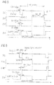
- the figure 1 shows schematically a device 100 according to the invention in a preferred embodiment.
- a device for controlling the power supply which finds its application in a light device, such as a signaling device, of a motor vehicle.
- a device comprises a power supply circuit 130 capable of converting a direct current of a first intensity supplied by an internal current source to the motor vehicle, such as a battery, into a charging current of a current. different intensity.
- Such means 130 present in a known manner an input called “enable” which allows them to be activated or deactivated respectively by means of a control signal.
- a plurality of light sources 120 exemplarily represented by light-emitting diodes, LEDs, are connected to the power supply means 130.
- the light sources 120 follow each other in the assembly.
- the plurality 120 is divided into a first group 122 and at least a second group 124.
- the second group of light sources 124 implements the light function "low beam" of a signaling device of a motor vehicle.
- the "high beam” light function requiring a higher luminous intensity, is implemented.
- Interrupting means 140 make it possible to switch between the two (or more) modes of operation by short-circuiting the least one of the groups. In the example shown, the interruption means 140 selectively bypass the first group 122.
- control means 150 configured to control on the one hand the supply means 130 by means of a control signal 152, and on the other hand the interruption means 140 to the using a command signal 154.
- the operation of the control means 150 is described with respect to the chronogram of the figure 1 .
- the input of the control means is illustrated by the signal 01.
- This signal represented in a binary manner may for example be from a non-illustrated computer system internal to the motor vehicle. It indicates the driver's willingness to turn on either LEDs 124 ("low beam") or all LEDs 122, 124 ("high beam”).
- the control means 150 initially disable the supply means 130, so that no LEDs are temporarily powered. This is achieved using the binary control signal 152.
- the interrupting means 140 While the power supply means 130 are deactivated, the interrupting means 140, initially in an open state, are switched to the closed state, thus short-circuiting the first group of LEDs 122. This is achieved by the binary control signal 154. Once the switching has been performed, the control means 150 reactivate the supply means 130 by means of the signal 152. At the restart of the power supply, means 130 are able to provide a current adapted to the load that has just been reduced by short-circuiting a portion of the LEDs of the series connection. Thus, the occurrence of a large current transient peak, potentially dangerous for the LEDs 124 is avoided.
- the control signal 154 of the interruption means 130 is therefore a delayed image of the received signal 01.
- the delay is preferably 50 to 100 ⁇ s while other values may be considered by the controller. skilled person.
- the signal 152 preferably deactivates the power supply means 130 about 50 ms before the switchover command is issued.
- the deactivation signal 152 is generally given immediately with the rising edge of the signal 01.
- the means 130 are preferably reactivated only after about 100 ⁇ s, once the failover command was issued. Obviously the exact values of these delays may deviate depending on the specific applications, without departing from the scope of the present invention.
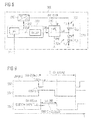
- the figure 3 shows for example an electronic circuit capable of producing the control signals 152, 154 shown on the timing diagram of the figure 2 , from the input signal 01.
- Embodiment 200 of the device illustrated by the figure 4 is similar to the one illustrated by the figure 1 .
- the control means 250 are made by a microcontroller element which makes it possible to generate control signals 252, 254 ', 254 ", and by an electronic circuit implementing the NOR (NOR) logic function. to realize the signals 252, 254 'and 254 "as shown in the timing diagram of the figure 5 .
- the input signal 01 is not represented.
- the state transitions of the three signals are synchronized with the rising edge of the signal 01.
- the microcontroller 250 first deactivates the power supply means 230 by changing the state of the binary signal 252 to "disable".
- a first control signal 254 ' which is an image of the signal 01, is transmitted on an output of the microcontroller.
- the signal 254 "is sent on a different output of the microcontroller and represents the delay to be applied to the rising edge of the interrupt signal
- the NOR logic gate combines the two signals 254 ', 254" to generate the signal 254, which controls the switching of the interruption means 240 to the closed state.
- the figure 6 shows an alternative example of the control signals generated by the microcontroller 250.
- the signals 254b 'and 254b are synchronized with respect to the rising edge of the control signal 252 of the power supply means 230.
- a logic gate this time of the OR type, makes it possible to combine the signals 254b ', 254b "in order to generate the control signal 254 of the interruption means 240.
- Embodiment 300 of the device illustrated by figure 8 is similar to the previously described embodiments.
- the control means 350 are made by a programmed microcontroller element which makes it possible to generate control signals 352, 354 'and by an electronic circuit implementing a delay.
- the microcontroller is programmed so as to produce the signals 352 and 354 'as shown on the timing diagram of the figure 9 .
- the input signal 01 is not represented.
- the state transitions of the two signals are synchronized with respect to the rising edge of the signal 01.
- the microcontroller 350 first deactivates the power supply means 330 by changing the state of the binary signal 352 to "disable”.
- a control signal 354 ' which is an image of the signal 01, is transmitted on an output of the microcontroller.
- the electronic circuit shown at the bottom of the figure 10 delays the signal 354 'to obtain the control signal 354 of the interruption means 340.
Landscapes
- Engineering & Computer Science (AREA)
- Mechanical Engineering (AREA)
- Power Engineering (AREA)
- Transportation (AREA)
- General Engineering & Computer Science (AREA)
- Lighting Device Outwards From Vehicle And Optical Signal (AREA)
- Circuit Arrangement For Electric Light Sources In General (AREA)
Abstract
Description
- L'invention a trait au domaine des dispositifs lumineux pour véhicules automobiles, et plus précisément aux moyens de pilotage de l'alimentation électrique de sources lumineuses au sein de tels dispositifs.
- Dans le domaine des dispositifs lumineux pour véhicules automobiles, et notamment des dispositifs de signalisation lumineuse, il devient de plus en plus courant de faire recours à des sources lumineuses à composants semiconducteurs, tels que par exemple des diodes électroluminescentes, LED. Par rapport à des sources lumineuses à incandescence ou à décharge, l'utilisation de LEDs permet de créer des signatures optiques originales en plaçant par exemple une pluralité de LEDs le long d'un contour prédéfini. Par ailleurs la consommation d'énergie de LEDs est de manière générale inférieure à celle de sources lumineuses traditionnelles. Un élément LED émet un rayonnement lumineux d'une intensité prédéfinie lorsqu'il est parcouru par un courant électrique d'une intensité prédéfinie et supérieure à une valeur seuil.
- De manière connue, un montage en série de plusieurs LED est monté en charge d'un dispositif de pilotage de l'alimentation électrique des LEDs. Un tel dispositif converti un courant électrique d'une première intensité, fourni de manière générale par une source de courant interne du véhicule automobile, telle qu'une batterie, en un courant électrique d'une deuxième intensité différente. La tension appliquée aux bornes du montage en série doit être telle que toutes les LEDs du montage puissent émettre un rayonnement lumineux.
- Pour une fonction lumineuse donnée, il est connu de fournir deux modes d'éclairage d'intensités lumineuses différentes. Un exemple est l'éclairage frontal en modes feux de route, HB (« High Beam »), et feux de croisement, LB (« Low Beam »), respectivement. Il est connu d'implémenter ce genre de fonctionnalité par un montage de deux groupes de LEDs en série, l'intégralité des LEDs étant alimenté par les mêmes moyens de pilotage de l'alimentation électrique. Un interrupteur permet de court-circuiter un des deux groupes de LEDs dans le montage. Lorsque le court-circuit est activé, l'intensité lumineuse émise par l'ensemble des LEDs est réduite puisqu'un des deux groupes de LEDs n'émet pas de rayonnement lumineux. Ce mode correspond par exemple au mode feux de croisement. La charge du convertisseur est également instantanément réduite lorsque le court-circuit est activé. Ce changement abrupt de la charge donne lieu à des pics de courants transitoires importants traversant les LEDs qui restent alimentées. Il a été observé que ces pics peuvent présenter des intensités au-delà de 4 A et peuvent avoir lieu pendant environ 20 µs. Cependant, la plupart des éléments LEDs disponibles ne supportent que des pics de courant allant jusqu'à environ 2,5 A. Dans de telles implémentations connues, il existe donc un réel risque d'endommagement des sources lumineuses.
- Il a été proposé d'absorber les pics transitoires dans de tels montages par absorption de l'énergie dans une résistance qui est sélectivement branchée dans le circuit de charge par un transistor lorsqu'un pic est détecté. De tels systèmes doivent cependant être redimensionnés pour chaque montage en charge et représentent une perte globale d'énergie puisqu'une partie de l'énergie produite est perdue dans la résistance.
- L'invention a pour objectif de pallier à au moins un des problèmes posés par l'art antérieur. Plus précisément, l'invention propose un dispositif et un procédé qui permet la prévention de l'apparition de pics de courant transitoires importants dans des montages tels qu'ils viennent d'être décrits, plutôt que de réduire l'impact de tels pics une fois qu'ils sont apparus.
- L'invention a pour objet un dispositif de pilotage de l'alimentation électrique d'une pluralité de sources lumineuses composée d'un premier groupe comprenant au moins une source lumineuse, monté en série avec au moins un deuxième groupe comprenant au moins une source lumineuse. Le dispositif comprend un circuit d'alimentation auquel la pluralité de sources lumineuses est branchée en charge. Le dispositif comprend également des moyens d'interruption qui permettent d'alimenter de manière sélective au moins un des premier ou deuxième groupes ou toute la pluralité de sources lumineuses. Le dispositif est remarquable en ce qu'il comprend des moyens de commande qui permettent de commander l'état d'activation du circuit d'alimentation et l'état des moyens d'interruption lorsqu'une commutation de l'alimentation de toute la pluralité de sources lumineuses à l'alimentation de l'un ou de certains seulement des groupes de sources lumineuses est requise.
- De préférence, le dispositif de pilotage de l'alimentation est un dispositif de pilotage de l'alimentation pour un système lumineux d'un véhicule automobile.
- Le circuit d'alimentation peut de préférence comprendre un convertisseur DC/DC, un convertisseur de type boost/buck, ou par exemple un convertisseur de type buck, réducteur de tension.
- De préférence, la pluralité de sources lumineuses peut être composée d'un premier groupe comprenant au moins une source lumineuse, monté en série avec un deuxième groupe comprenant au moins une source lumineuse.
- Les moyens de commande peuvent de préférence être configurés de façon à réaliser les étapes suivantes lorsqu'une commutation de l'alimentation de toute la pluralité de sources lumineuses à l'alimentation du deuxième groupe de sources lumineuses est requise :
- réception d'un signal indiquant la commutation requise, puis
- désactivation du circuit d'alimentation, puis
- commutation des moyens d'interruption, pendant que le circuit d'alimentation est désactivé, de façon à court-circuiter le premier groupe de sources lumineuses ;
- réactivation du circuit d'alimentation.
- De manière préférée, le circuit d'alimentation est désactivé pendant 100 à 200 microsecondes sur réception du signal. La commutation des moyens d'interruption peut avantageusement être réalisée avec un délai par rapport à la réception du signal indiquant la commutation requise. D'autres durées de désactivation sont envisageables en fonction des composants électroniques utilisés dans le dispositif.
- Le délai peut de préférence être de l'ordre de 50 à 100 microsecondes. D'autres durées de délai sont envisageables en fonction des caractéristiques techniques et propriétés des composants électroniques utilisés dans le dispositif.
- De préférence, les moyens de commande peuvent comprendre un circuit électronique qui réalise la fonction de délai de commutation.
- Les moyens de commande peuvent de préférence comprendre un circuit électronique qui réalise la fonction de désactivation du circuit de pilotage.
- De manière préférée, les moyens de commande peuvent comprendre un élément microcontrôleur configuré de manière à réaliser la fonction de délai de commutation et/ou de désactivation du circuit de pilotage.
- Les moyens de commande peuvent de manière préférée comprendre en outre des moyens de combinaison logiques de signaux émis par l'élément microcontrôleur. Il peut par exemple s'agir de portes logiques OU (OR) ou NON-OU (NOR).
- Le premier et/ou le deuxième groupe peut de préférence comprendre une pluralité de sources lumineuses branchées en série.
- De préférence, les sources lumineuses peuvent comprendre un composant semiconducteur, notamment une diode électroluminescente, LED, une diode électroluminescente de puissance ou une diode électroluminescente organique. Elles peuvent également comprendre une diode laser.
- L'invention a également pour objet un dispositif lumineux pour un véhicule automobile. Le dispositif comprend des moyens de pilotage de l'alimentation électrique d'une pluralité de sources lumineuses composée d'un premier groupe comprenant au moins une source lumineuse, monté en série avec un deuxième groupe comprenant au moins une source lumineuse. Le dispositif lumineux est remarquable en ce que les moyens de pilotage sont conformes au dispositif selon l'invention. De préférence, le dispositif lumineux peut être un dispositif de signalisation d'un véhicule automobile.
- Le premier groupe à lui seul peut de préférence implémenter la fonction lumineuse « feux de croisement », et les premier et deuxième groupes ensemble peuvent avantageusement implémenter la fonction lumineuse « feux de route » d'un véhicule automobile.
- L'invention a également pour objet un procédé de pilotage de l'alimentation électrique d'une pluralité de sources lumineuses composée d'un premier groupe comprenant au moins une source lumineuse, monté en série avec un deuxième groupe comprenant au moins une source. Le procédé comprend les étapes suivantes :
- mise à disposition d'un circuit d'alimentation auquel la pluralité de sources lumineuses est branchée en charge ;
- mise à disposition de moyens d'interruption qui permettent d'alimenter de manière sélective le deuxième groupe ou la pluralité de sources lumineuses.
- Le procédé est remarquable en ce qu'il comprend en outre l'étape suivante :
- commander l'état d'activation du circuit d'alimentation et l'état des moyens d'interruption lorsqu'une commutation de l'alimentation de toute la pluralité de sources lumineuses à l'alimentation du deuxième groupe de sources lumineuses est requise.
- De préférence, le procédé peut comprendre les étapes suivantes :
- réception d'un signal indiquant la commutation requise, puis
- désactivation du circuit d'alimentation, puis
- commutation des moyens d'interruption, pendant que le circuit d'alimentation est désactivé, de façon à court-circuiter le premier groupe de sources lumineuses ;
- réactivation du circuit d'alimentation.
- Les mesures de l'invention permettent de réduire de manière efficace les pics de courants transitoires qui peuvent apparaître dans des dispositifs connus, lorsqu'une partie des sources lumineuses branchées en série d'un dispositif d'alimentation est temporairement court-circuité. Au lieu de dissiper un surplus d'énergie temporel dans une résistance engendrant des pertes, l'invention utilise une commande intelligente des signaux de contrôle afin d'éviter l'apparition des pics de courant. Ceci présente l'avantage de ne pas perdre le surplus d'énergie et de ne pas devoir avoir recours à des résistances de dissipation, qui utilisent un espace conséquent sur circuit imprimé. De plus, selon des modes de réalisations préférés, la solution selon l'invention peut être mise à échelle sans devoir redimensionner les composants électroniques impliqués. Les modes de réalisation présentés permettent une implémentation des mesures selon l'invention soit par circuits électroniques, soit par programmation d'un élément microcontrôleur, soit par une solution hybride impliquant des circuits électroniques et un élément programmable. Cette flexibilité rend l'invention applicable à de nombreux dispositifs lumineux existants, dont la longévité et la durabilité sont ainsi augmentées.
- D'autres caractéristiques et avantages de la présente invention seront mieux compris à l'aide de la description exemplaire et des dessins parmi lesquels :
- la
figure 1 est une illustration schématique d'un dispositif selon un mode de réalisation préféré de l'invention ; - la
figure 2 est un chronogramme de signaux de commande impliqués dans le fonctionnement d'un dispositif selon un mode de réalisation préféré de l'invention ; - la
figure 3 montre un exemple d'implémentation d'un détail d'un dispositif selon un mode de réalisation préféré de l'invention ; - la
figure 4 est une illustration schématique d'un dispositif selon un mode de réalisation préféré de l'invention ; - la
figure 5 est un chronogramme de signaux de commande impliqués dans le fonctionnement d'un dispositif selon un mode de réalisation préféré de l'invention ; - la
figure 6 est un chronogramme de signaux de commande impliqués dans le fonctionnement d'un dispositif selon un mode de réalisation préféré de l'invention ; - la
figure 7 montre un exemple d'implémentation d'un détail d'un dispositif selon un mode de réalisation préféré de l'invention ; - la
figure 8 est une illustration schématique d'un dispositif selon un mode de réalisation préféré de l'invention ; - la
figure 9 est un chronogramme de signaux de commande impliqués dans le fonctionnement d'un dispositif selon un mode de réalisation préféré de l'invention ; - la
figure 10 montre un exemple d'implémentation d'un détail d'un dispositif selon un mode de réalisation préféré de l'invention. - Dans la description qui suit, des numéros de référence similaires seront utilisés pour décrire des concepts similaires à travers des modes de réalisation différents de l'invention. Ainsi, les numéros 100, 200 et 300 décrivent un dispositif dans trois modes de réalisation différents conformes à l'invention.
- Sauf indication spécifique du contraire, des caractéristiques techniques décrites en détail pour un mode de réalisation donné peuvent être combinées aux caractéristiques techniques décrites dans le contexte d'autres modes de réalisation décrits à titre exemplaire et non limitatif.
- La
figure 1 montre de manière schématique un dispositif 100 selon l'invention dans un mode de réalisation préférentiel. De préférence, il s'agit d'un dispositif de pilotage de l'alimentation électrique qui trouve son application dans un dispositif lumineux, tel qu'un dispositif de signalisation, d'un véhicule automobile. De manière connue, un tel dispositif comprend un circuit d'alimentation 130 capable de convertir un courant continu d'une première intensité fourni par une source de courant interne au véhicule automobile, telle qu'une batterie, en un courant de charge d'une intensité différente. De tels moyens 130 présentent de manière connue une entrée dite « enable » qui permet de les activer ou désactiver respectivement à l'aide d'un signal de commande. Une pluralité de sources lumineuses 120, représentées de manière exemplaire par des diodes électroluminescentes, LEDs, est branchée en charge des moyens d'alimentation 130. Les sources lumineuses 120 se suivent dans le montage. La pluralité 120 est divisée en un premier groupe 122 et au moins un deuxième groupe 124. Pour clarifier la figure, un seul deuxième groupe 124 est illustré, sans pour autant limiter l'invention à cet exemple. Dans une application préférée du dispositif 100, le deuxième groupe de sources lumineuses 124 implémente la fonction lumineuse « feux de croisement » d'un dispositif de signalisation d'un véhicule automobile. Lorsque le premier et le deuxième groupe de sources lumineuses 122, 124 sont alimentés, la fonction lumineuse « feux de route », nécessitant une intensité lumineuse plus élevée, est implémentée. Des moyens d'interruption 140 permettent de basculer entre les deux (ou plusieurs) modes de fonctionnement en court-circuitant au moins un des groupes. Dans l'exemple montré, les moyens d'interruption 140 permettent de court-circuiter de manière sélective le premier groupe 122. - Finalement, le dispositif 100 comprend des moyens de commande 150 configurés pour commander d'une part les moyens d'alimentation 130 à l'aide d'un signal de commande 152, et d'autre part les moyens d'interruption 140 à l'aide d'un signal de commande 154.
- Le fonctionnement des moyens de commande 150 est décrit par rapport au chronogramme de la
figure 1 . L'entrée des moyens de commande est illustrée par le signal 01. Ce signal représenté de façon binaire peut par exemple être issu d'un système informatique non-illustré interne au véhicule automobile. Il indique la volonté du conducteur d'allumer soit les LEDs 124 (« feux de croisement »), soit toutes les LEDs 122, 124 (« feux de route »). Lorsqu'un passage du mode « feux de route » vers le mode « feux de croisement » est demandé par le signal 01, les moyens de commande 150 désactivent dans un premier temps les moyens d'alimentation 130, de façon à ce qu'aucune des LEDs ne soit alimentée temporairement. Ceci est réalisé à l'aide du signal de commande binaire 152. Alors que les moyens d'alimentation 130 sont désactivés, les moyens d'interruption 140, initialement dans un état ouvert, sont basculés vers l'état fermé, court-circuitant ainsi le premier groupe de LEDs 122. Ceci est réalisé par le signal de commande binaire 154. Une fois le basculement réalisé, les moyens de commande 150 réactivent les moyens d'alimentation 130 à l'aide du signal 152. A la reprise de l'alimentation, les moyens 130 sont aptes à fournir un courant adapté à la charge qui vient d'être réduite par court-circuitage d'une partie des LEDs du montage en série. Ainsi, l'apparition d'un pic transitoire de courant important, potentiellement dangereux pour les LEDs 124 est évitée. Alors que des solutions connues dans l'art peuvent produire des pics transitoires d'environ 4,1 A, en utilisant les mesures de l'invention, ces pics ont été réduits à 2.2 A, ce qui représente un ordre de grandeur acceptable pour la plupart de LEDs disponibles. Evidemment, par la suite, le dispositif peut être rebasculé en mode « feux de route » pour revenir à son état initial. - Le signal de commande 154 des moyens d'interruption 130 est donc une image retardée du signal reçu 01. Dans des modes de réalisations typiques, le retard est de préférence de 50 à 100 µs tandis que d'autres valeurs peuvent être considérées par l'homme du métier. Afin que le basculement des moyen d'interruptions puisse se réaliser lorsque l'alimentation des LEDs est coupée, le signal 152 désactive de préférence les moyens d'alimentation 130 environ 50 ms avant que la commande de basculement ne soit émise. Le signal de désactivation 152 est en général donné immédiatement avec le flanc montant du signal 01. Les moyens 130 ne sont réactivés de préférence qu'après environ 100 µs, une fois que la commande de basculement a été émise. Evidemment les valeurs exactes de ces délais peuvent dévier selon les applications spécifiques, sans pour autant sortir du cadre de la présente invention.
- L'homme du métier saura implémenter cette fonctionnalité logique de plusieurs façons. La
figure 3 montre par exemple un circuit électronique capable de réaliser les signaux de commande 152, 154 montrés sur le chronogramme de lafigure 2 , à partir du signal d'entrée 01. - Le mode de réalisation 200 du dispositif illustré par la
figure 4 est semblable à celui illustré par lafigure 1 . Cependant, les moyens de commandes 250 sont réalisés par un élément microcontrôleur qui permet de générer des signaux de commandes 252, 254', 254", et par un circuit électronique implémentant la fonction logique NON-OU (NOR). Le microcontrôleur est programmé de manière à réaliser les signaux 252, 254' et 254" tels que montrés sur le chronogramme de lafigure 5 . Le signal d'entrée 01 n'y est pas représenté. Les transitions d'états des trois signaux sont synchronisées par rapport au flanc montant du signal 01. Le microcontrôleur 250 désactive d'abord les moyens d'alimentation 230 en changeant l'état du signal binaire 252 sur « disable ». En même temps, un premier signal de commande 254', qui est une image du signal 01, est émis sur une sortie du microcontrôleur. Le signal 254" est émis sur une sortie différente du microcontrôleur et représente le retard à appliquer au flanc montant du signal d'interruption. Finalement, la porte logique NON-OU combine les deux signaux 254', 254" pour générer le signal 254, qui commande le basculement des moyens d'interruption 240 vers l'état fermé. Une fois la commande basculement générée, les moyens d'alimentation 230 sont réactivés par le signal 252 après un laps de temps prédéterminé. - La
figure 6 montre un exemple alternatif des signaux de commande générés par le microcontrôleur 250. Ici, les signaux 254b' et 254b" sont synchronisés par rapport au flanc montant du signal de contrôle 252 des moyens d'alimentation 230. Comme pour le mode de réalisation précédent, une porte logique, cette fois de type OU, permet de combiner les signaux 254b', 254b" afin de générer le signal de commande 254 des moyens d'interruption 240. Un exemple d'implémentation correspondant d'un circuit électronique pour réaliser la fonction OU et les moyens d'interruption 240, impliquant notamment des transistors, et illustré par lafigure 7 . - Le mode de réalisation 300 du dispositif illustré par la
figure 8 est semblable aux modes de réalisation décrits au préalable. Cependant, les moyens de commandes 350 sont réalisés par un élément microcontrôleur programmé qui permet de générer des signaux de commandes 352, 354' et par un circuit électronique implémentant un retard. - Le microcontrôleur est programmé de manière à réaliser les signaux 352 et 354' tels que montrés sur le chronogramme de la
figure 9 . Le signal d'entrée 01 n'y est pas représenté. Les transitions d'états des deux signaux sont synchronisées par rapport au flanc montant du signal 01. Le microcontrôleur 350 désactive d'abord les moyens d'alimentation 330 en changeant l'état du signal binaire 352 sur « disable ». En même temps, un signal de commande 354', qui est une image du signal 01, est émise sur une sortie du microcontrôleur. Le circuit électronique montré en bas de lafigure 10 retarde le signal 354' pour obtenir le signal de commande 354 des moyens d'interruption 340.
Claims (15)
- Dispositif (100, 200, 300) de pilotage de l'alimentation électrique d'une pluralité de sources lumineuses (120, 220, 320) composée d'un premier groupe (122, 222, 322) comprenant au moins une source lumineuse, monté en série avec au moins un deuxième groupe (124, 224, 324) comprenant au moins une source lumineuse,
le dispositif comprenant un circuit d'alimentation (130, 230, 330) auquel la pluralité de sources lumineuses (120, 220, 320) est branchée en charge,
et des moyens d'interruption (140, 240, 340) qui permettent d'alimenter de manière sélective au moins un des premier ou deuxième groupes ou toute la pluralité de sources lumineuses,
caractérisé en ce que le dispositif comprend en outre des moyens de commande (150, 250, 350) qui permettent de commander l'état d'activation du circuit d'alimentation (130, 230, 330) et l'état des moyens d'interruption (140, 240, 340) lorsqu'une commutation de l'alimentation de toute la pluralité de sources lumineuses à l'alimentation de l'un ou de certains seulement des groupes de sources lumineuses est requise. - Dispositif selon la revendication 1, caractérisé en ce que la pluralité de sources lumineuses (120, 220, 320) est composée d'un premier groupe (122, 222, 322) comprenant au moins une source lumineuse, monté en série avec un deuxième groupe (124, 224, 324) comprenant au moins une source lumineuse.
- Dispositif selon une des revendications 1 ou 2, caractérisé en ce que les moyens de commande (150, 250, 350) sont configurés de façon à réaliser les étapes suivantes lorsqu'une commutation de l'alimentation de toute la pluralité de sources lumineuses à l'alimentation du deuxième groupe de sources lumineuses est requise :- réception d'un signal (01) indiquant la commutation requise, puis- désactivation du circuit d'alimentation (130, 230, 330), puis- commutation des moyens d'interruption (140, 240, 340), pendant que le circuit d'alimentation est désactivé, de façon à court-circuiter le premier groupe de sources lumineuses ;- réactivation du circuit d'alimentation (130, 230, 330).
- Dispositif selon la revendication 3, caractérisé en ce que le circuit d'alimentation est désactivé pendant 100 à 200 microsecondes sur réception du signal, et en ce que la commutation des moyens d'interruption est réalisée avec un délai par rapport à la réception du signal.
- Dispositif selon la revendication 4, caractérisé en ce que le délai est de l'ordre de 50 à 100 microsecondes.
- Dispositif selon une des revendications 1 à 5, caractérisé en ce que les moyens de commande comprennent un circuit électronique qui réalise la fonction de délai de commutation.
- Dispositif selon une des revendications 1 à 6, caractérisé en ce que les moyens de commande comprennent un circuit électronique qui réalise la fonction de désactivation du circuit de pilotage.
- Dispositif selon une des revendications 1 à 7, caractérisé en ce que les moyens de commande comprennent un élément microcontrôleur configuré de manière à réaliser la fonction de délai de commutation et/ou de désactivation du circuit de pilotage.
- Dispositif selon la revendication 8, caractérisé en ce que les moyens de commande comprennent en outre des moyens de combinaison logique de signaux émis par l'élément microcontrôleur.
- Dispositif selon une des revendications 1 à 9, caractérisé en ce que le premier et/ou le deuxième groupe comprend une pluralité de sources lumineuses branchées en série.
- Dispositif selon une des revendications 1 à 10, caractérisé en ce que les sources lumineuses comprennent un composant semiconducteur, notamment une diode électroluminescente, LED.
- Dispositif lumineux pour un véhicule automobile, le dispositif comprenant des moyens de pilotage de l'alimentation électrique d'une pluralité de sources lumineuses composée d'un premier groupe comprenant au moins une source lumineuse, monté en série avec un deuxième groupe comprenant au moins une source lumineuse, caractérisé en ce que les moyens de pilotage sont conformes au dispositif selon une des revendication 1 à 11.
- Dispositif selon la revendication 12, caractérisé en ce que le premier groupe à lui seul implémente la fonction lumineuse « feux de croisement », et en ce que les premier et deuxième groupes ensemble implémentent la fonction lumineuse « feux de route ».
- Procédé de pilotage de l'alimentation électrique d'une pluralité de sources lumineuses composée d'un premier groupe comprenant au moins une source lumineuse, monté en série avec un deuxième groupe comprenant au moins une source, comprenant les étapes suivantes :- mise à disposition d'un circuit d'alimentation auquel la pluralité de sources lumineuses est branchée en charge ;- mise à disposition de moyens d'interruption qui permettent d'alimenter de manière sélective le deuxième groupe ou la pluralité de sources lumineuses ;caractérisé en ce que le procédé comprend en outre l'étape suivante :- commander l'état d'activation du circuit d'alimentation et l'état des moyens d'interruption lorsqu'une commutation de l'alimentation de toute la pluralité de sources lumineuses à l'alimentation du deuxième groupe de sources lumineuses est requise.
- Procédé selon la revendication 14, caractérisé en ce qu'il comprend les étapes suivantes :- réception d'un signal indiquant la commutation requise, puis- désactivation du circuit d'alimentation, puis- commutation des moyens d'interruption, pendant que le circuit d'alimentation est désactivé, de façon à court-circuiter le premier groupe de sources lumineuses ;- réactivation du circuit d'alimentation.
Applications Claiming Priority (1)
| Application Number | Priority Date | Filing Date | Title |
|---|---|---|---|
| FR1554311A FR3036248B1 (fr) | 2015-05-13 | 2015-05-13 | Limiteur de pics de courants transitoires lors de variations de charges led |
Publications (2)
| Publication Number | Publication Date |
|---|---|
| EP3093555A1 true EP3093555A1 (fr) | 2016-11-16 |
| EP3093555B1 EP3093555B1 (fr) | 2018-09-19 |
Family
ID=53776767
Family Applications (1)
| Application Number | Title | Priority Date | Filing Date |
|---|---|---|---|
| EP16169046.6A Active EP3093555B1 (fr) | 2015-05-13 | 2016-05-10 | Limiteur de pics de courants transitoires lors de variations de charges led |
Country Status (4)
| Country | Link |
|---|---|
| US (1) | US9775203B2 (fr) |
| EP (1) | EP3093555B1 (fr) |
| CN (1) | CN106162980B (fr) |
| FR (1) | FR3036248B1 (fr) |
Families Citing this family (3)
| Publication number | Priority date | Publication date | Assignee | Title |
|---|---|---|---|---|
| NL2016662B1 (en) * | 2016-04-22 | 2017-11-16 | Eldolab Holding Bv | Modular lighting application. |
| JPWO2018186187A1 (ja) * | 2017-04-04 | 2020-02-13 | 株式会社小糸製作所 | 車両用灯具 |
| CN107135581B (zh) * | 2017-07-02 | 2019-07-19 | 深圳市青蓝半导体有限公司 | 一种基于线性恒流的远近光车灯控制电路 |
Citations (1)
| Publication number | Priority date | Publication date | Assignee | Title |
|---|---|---|---|---|
| US20110260617A1 (en) * | 2010-04-23 | 2011-10-27 | Panasonic Electric Works Co., Ltd. | Lighting device, headlamp apparatus and vehicle using same |
Family Cites Families (4)
| Publication number | Priority date | Publication date | Assignee | Title |
|---|---|---|---|---|
| JP4578861B2 (ja) * | 2004-05-28 | 2010-11-10 | ハリソン東芝ライティング株式会社 | 高圧放電灯の点灯装置 |
| US7994725B2 (en) * | 2008-11-06 | 2011-08-09 | Osram Sylvania Inc. | Floating switch controlling LED array segment |
| US8174212B2 (en) * | 2008-11-30 | 2012-05-08 | Microsemi Corp.—Analog Mixed Signal Group Ltd. | LED string driver with light intensity responsive to input voltage |
| TWI538553B (zh) * | 2009-08-25 | 2016-06-11 | 皇家飛利浦電子股份有限公司 | 多通道照明單元及供應電流至其光源之驅動器 |
-
2015
- 2015-05-13 FR FR1554311A patent/FR3036248B1/fr active Active
-
2016
- 2016-05-10 EP EP16169046.6A patent/EP3093555B1/fr active Active
- 2016-05-12 US US15/152,903 patent/US9775203B2/en active Active
- 2016-05-13 CN CN201610319484.5A patent/CN106162980B/zh active Active
Patent Citations (1)
| Publication number | Priority date | Publication date | Assignee | Title |
|---|---|---|---|---|
| US20110260617A1 (en) * | 2010-04-23 | 2011-10-27 | Panasonic Electric Works Co., Ltd. | Lighting device, headlamp apparatus and vehicle using same |
Also Published As
| Publication number | Publication date |
|---|---|
| US20160338160A1 (en) | 2016-11-17 |
| US9775203B2 (en) | 2017-09-26 |
| CN106162980A (zh) | 2016-11-23 |
| CN106162980B (zh) | 2019-08-09 |
| EP3093555B1 (fr) | 2018-09-19 |
| FR3036248B1 (fr) | 2017-06-16 |
| FR3036248A1 (fr) | 2016-11-18 |
Similar Documents
| Publication | Publication Date | Title |
|---|---|---|
| FR3048580B1 (fr) | Alimentation electrique pour un dispositif lumineux d'un vehicule automobile comprenant une pluralite de sorties | |
| FR3018659A1 (fr) | Lampe pour vehicule et dispositif de commande de lampe pour vehicule | |
| EP3367754B1 (fr) | Procédé et module de commande pour sources lumineuses à flux lumineux pulsé d'un véhicule automobile | |
| FR3034949A1 (fr) | Circuit d'eclairage | |
| EP2966941B1 (fr) | Système de pilotage de l'alimentation électrique et de gestion thermique de sources lumineuses | |
| FR3046330A1 (fr) | Circuit d'eclairage et feu clignotant de vehicule | |
| EP3093555B1 (fr) | Limiteur de pics de courants transitoires lors de variations de charges led | |
| FR3066351A1 (fr) | Circuit de commande et feu de vehicule | |
| EP3589078A1 (fr) | Dispositif de pilotage de l`alimentation electrique de sources lumineuses d'un vehicule automobile en fonction des variations de leurs temperatures | |
| EP3088247B1 (fr) | Dispositif lumineux réalisant plusieurs fonctions lumineuses d'un véhicule automobile à l'aide de groupes de sources de lumière dédiés par fonction | |
| FR2845328A1 (fr) | Lampe de vehicule a mode de fonctionnement multiple | |
| FR2889130A1 (fr) | Dispositif de commande d'eclairage pour phare de vehicule | |
| FR3089747A1 (fr) | Circuit d'allumage et feu de véhicule | |
| FR3008773A1 (fr) | Phare pour vehicule | |
| EP3099140A1 (fr) | Module lumineux pour un dispositif lumineux de véhicule automobile et procédé d'utilisation correspondant | |
| FR3078383A1 (fr) | Module lumineux pour un vehicule automobile comprenant une pluralite de branches de sources lumineuses | |
| WO2013072602A1 (fr) | Variateur de puissance | |
| EP3451797A1 (fr) | Dispositif de pilotage de l' alimentation de sources lumineuses comprenant plusieurs entrees protegees | |
| FR2999127A1 (fr) | Dispositif d'eclairage comprenant un premier dispositif lumineux et un deuxieme dispositif lumineux susceptibles d'etre allumes selectivement | |
| EP3355460B1 (fr) | Dispositif de pilotage de l'alimentation de sources lumineuses d'un véhicule automobile | |
| EP3416255A1 (fr) | Alimentation électrique stabilisée en modulation de largeur d'impulsions | |
| FR3066661B1 (fr) | Convertisseur a plages de tension de sortie selectionnables | |
| FR3065613A1 (fr) | Dispositif d'alimentation selective de lampe a incandescence ou de diode electroluminescente | |
| FR3095570A1 (fr) | Dispositif de pilotage de sources lumineuses a commutation rapide | |
| FR3107865A1 (fr) | Dispositif d'éclairage automobile |
Legal Events
| Date | Code | Title | Description |
|---|---|---|---|
| PUAI | Public reference made under article 153(3) epc to a published international application that has entered the european phase |
Free format text: ORIGINAL CODE: 0009012 |
|
| AK | Designated contracting states |
Kind code of ref document: A1 Designated state(s): AL AT BE BG CH CY CZ DE DK EE ES FI FR GB GR HR HU IE IS IT LI LT LU LV MC MK MT NL NO PL PT RO RS SE SI SK SM TR |
|
| AX | Request for extension of the european patent |
Extension state: BA ME |
|
| STAA | Information on the status of an ep patent application or granted ep patent |
Free format text: STATUS: REQUEST FOR EXAMINATION WAS MADE |
|
| 17P | Request for examination filed |
Effective date: 20170505 |
|
| RBV | Designated contracting states (corrected) |
Designated state(s): AL AT BE BG CH CY CZ DE DK EE ES FI FR GB GR HR HU IE IS IT LI LT LU LV MC MK MT NL NO PL PT RO RS SE SI SK SM TR |
|
| STAA | Information on the status of an ep patent application or granted ep patent |
Free format text: STATUS: EXAMINATION IS IN PROGRESS |
|
| 17Q | First examination report despatched |
Effective date: 20170830 |
|
| REG | Reference to a national code |
Ref country code: DE Ref legal event code: R079 Ref document number: 602016005654 Country of ref document: DE Free format text: PREVIOUS MAIN CLASS: F21S0008100000 Ipc: H05B0033080000 |
|
| GRAP | Despatch of communication of intention to grant a patent |
Free format text: ORIGINAL CODE: EPIDOSNIGR1 |
|
| STAA | Information on the status of an ep patent application or granted ep patent |
Free format text: STATUS: GRANT OF PATENT IS INTENDED |
|
| RIC1 | Information provided on ipc code assigned before grant |
Ipc: F21S 41/663 20180101ALI20180321BHEP Ipc: B60L 1/14 20060101ALI20180321BHEP Ipc: H05B 33/08 20060101AFI20180321BHEP Ipc: B60Q 1/14 20060101ALI20180321BHEP |
|
| INTG | Intention to grant announced |
Effective date: 20180412 |
|
| RIN1 | Information on inventor provided before grant (corrected) |
Inventor name: DIALLO, MASSOURANG Inventor name: WACHEUX, PATRICK |
|
| GRAS | Grant fee paid |
Free format text: ORIGINAL CODE: EPIDOSNIGR3 |
|
| GRAA | (expected) grant |
Free format text: ORIGINAL CODE: 0009210 |
|
| STAA | Information on the status of an ep patent application or granted ep patent |
Free format text: STATUS: THE PATENT HAS BEEN GRANTED |
|
| AK | Designated contracting states |
Kind code of ref document: B1 Designated state(s): AL AT BE BG CH CY CZ DE DK EE ES FI FR GB GR HR HU IE IS IT LI LT LU LV MC MK MT NL NO PL PT RO RS SE SI SK SM TR |
|
| REG | Reference to a national code |
Ref country code: GB Ref legal event code: FG4D Free format text: NOT ENGLISH |
|
| REG | Reference to a national code |
Ref country code: CH Ref legal event code: EP |
|
| REG | Reference to a national code |
Ref country code: DE Ref legal event code: R096 Ref document number: 602016005654 Country of ref document: DE |
|
| REG | Reference to a national code |
Ref country code: AT Ref legal event code: REF Ref document number: 1044858 Country of ref document: AT Kind code of ref document: T Effective date: 20181015 |
|
| REG | Reference to a national code |
Ref country code: IE Ref legal event code: FG4D Free format text: LANGUAGE OF EP DOCUMENT: FRENCH |
|
| REG | Reference to a national code |
Ref country code: NL Ref legal event code: MP Effective date: 20180919 |
|
| PG25 | Lapsed in a contracting state [announced via postgrant information from national office to epo] |
Ref country code: SE Free format text: LAPSE BECAUSE OF FAILURE TO SUBMIT A TRANSLATION OF THE DESCRIPTION OR TO PAY THE FEE WITHIN THE PRESCRIBED TIME-LIMIT Effective date: 20180919 Ref country code: RS Free format text: LAPSE BECAUSE OF FAILURE TO SUBMIT A TRANSLATION OF THE DESCRIPTION OR TO PAY THE FEE WITHIN THE PRESCRIBED TIME-LIMIT Effective date: 20180919 Ref country code: NO Free format text: LAPSE BECAUSE OF FAILURE TO SUBMIT A TRANSLATION OF THE DESCRIPTION OR TO PAY THE FEE WITHIN THE PRESCRIBED TIME-LIMIT Effective date: 20181219 Ref country code: GR Free format text: LAPSE BECAUSE OF FAILURE TO SUBMIT A TRANSLATION OF THE DESCRIPTION OR TO PAY THE FEE WITHIN THE PRESCRIBED TIME-LIMIT Effective date: 20181220 Ref country code: LT Free format text: LAPSE BECAUSE OF FAILURE TO SUBMIT A TRANSLATION OF THE DESCRIPTION OR TO PAY THE FEE WITHIN THE PRESCRIBED TIME-LIMIT Effective date: 20180919 Ref country code: BG Free format text: LAPSE BECAUSE OF FAILURE TO SUBMIT A TRANSLATION OF THE DESCRIPTION OR TO PAY THE FEE WITHIN THE PRESCRIBED TIME-LIMIT Effective date: 20181219 Ref country code: FI Free format text: LAPSE BECAUSE OF FAILURE TO SUBMIT A TRANSLATION OF THE DESCRIPTION OR TO PAY THE FEE WITHIN THE PRESCRIBED TIME-LIMIT Effective date: 20180919 |
|
| REG | Reference to a national code |
Ref country code: LT Ref legal event code: MG4D |
|
| PG25 | Lapsed in a contracting state [announced via postgrant information from national office to epo] |
Ref country code: LV Free format text: LAPSE BECAUSE OF FAILURE TO SUBMIT A TRANSLATION OF THE DESCRIPTION OR TO PAY THE FEE WITHIN THE PRESCRIBED TIME-LIMIT Effective date: 20180919 Ref country code: AL Free format text: LAPSE BECAUSE OF FAILURE TO SUBMIT A TRANSLATION OF THE DESCRIPTION OR TO PAY THE FEE WITHIN THE PRESCRIBED TIME-LIMIT Effective date: 20180919 Ref country code: HR Free format text: LAPSE BECAUSE OF FAILURE TO SUBMIT A TRANSLATION OF THE DESCRIPTION OR TO PAY THE FEE WITHIN THE PRESCRIBED TIME-LIMIT Effective date: 20180919 |
|
| REG | Reference to a national code |
Ref country code: AT Ref legal event code: MK05 Ref document number: 1044858 Country of ref document: AT Kind code of ref document: T Effective date: 20180919 |
|
| PG25 | Lapsed in a contracting state [announced via postgrant information from national office to epo] |
Ref country code: IT Free format text: LAPSE BECAUSE OF FAILURE TO SUBMIT A TRANSLATION OF THE DESCRIPTION OR TO PAY THE FEE WITHIN THE PRESCRIBED TIME-LIMIT Effective date: 20180919 Ref country code: RO Free format text: LAPSE BECAUSE OF FAILURE TO SUBMIT A TRANSLATION OF THE DESCRIPTION OR TO PAY THE FEE WITHIN THE PRESCRIBED TIME-LIMIT Effective date: 20180919 Ref country code: EE Free format text: LAPSE BECAUSE OF FAILURE TO SUBMIT A TRANSLATION OF THE DESCRIPTION OR TO PAY THE FEE WITHIN THE PRESCRIBED TIME-LIMIT Effective date: 20180919 Ref country code: IS Free format text: LAPSE BECAUSE OF FAILURE TO SUBMIT A TRANSLATION OF THE DESCRIPTION OR TO PAY THE FEE WITHIN THE PRESCRIBED TIME-LIMIT Effective date: 20190119 Ref country code: AT Free format text: LAPSE BECAUSE OF FAILURE TO SUBMIT A TRANSLATION OF THE DESCRIPTION OR TO PAY THE FEE WITHIN THE PRESCRIBED TIME-LIMIT Effective date: 20180919 Ref country code: PL Free format text: LAPSE BECAUSE OF FAILURE TO SUBMIT A TRANSLATION OF THE DESCRIPTION OR TO PAY THE FEE WITHIN THE PRESCRIBED TIME-LIMIT Effective date: 20180919 Ref country code: NL Free format text: LAPSE BECAUSE OF FAILURE TO SUBMIT A TRANSLATION OF THE DESCRIPTION OR TO PAY THE FEE WITHIN THE PRESCRIBED TIME-LIMIT Effective date: 20180919 Ref country code: CZ Free format text: LAPSE BECAUSE OF FAILURE TO SUBMIT A TRANSLATION OF THE DESCRIPTION OR TO PAY THE FEE WITHIN THE PRESCRIBED TIME-LIMIT Effective date: 20180919 Ref country code: ES Free format text: LAPSE BECAUSE OF FAILURE TO SUBMIT A TRANSLATION OF THE DESCRIPTION OR TO PAY THE FEE WITHIN THE PRESCRIBED TIME-LIMIT Effective date: 20180919 |
|
| PG25 | Lapsed in a contracting state [announced via postgrant information from national office to epo] |
Ref country code: PT Free format text: LAPSE BECAUSE OF FAILURE TO SUBMIT A TRANSLATION OF THE DESCRIPTION OR TO PAY THE FEE WITHIN THE PRESCRIBED TIME-LIMIT Effective date: 20190119 Ref country code: SM Free format text: LAPSE BECAUSE OF FAILURE TO SUBMIT A TRANSLATION OF THE DESCRIPTION OR TO PAY THE FEE WITHIN THE PRESCRIBED TIME-LIMIT Effective date: 20180919 Ref country code: SK Free format text: LAPSE BECAUSE OF FAILURE TO SUBMIT A TRANSLATION OF THE DESCRIPTION OR TO PAY THE FEE WITHIN THE PRESCRIBED TIME-LIMIT Effective date: 20180919 |
|
| REG | Reference to a national code |
Ref country code: DE Ref legal event code: R097 Ref document number: 602016005654 Country of ref document: DE |
|
| PLBE | No opposition filed within time limit |
Free format text: ORIGINAL CODE: 0009261 |
|
| STAA | Information on the status of an ep patent application or granted ep patent |
Free format text: STATUS: NO OPPOSITION FILED WITHIN TIME LIMIT |
|
| PG25 | Lapsed in a contracting state [announced via postgrant information from national office to epo] |
Ref country code: DK Free format text: LAPSE BECAUSE OF FAILURE TO SUBMIT A TRANSLATION OF THE DESCRIPTION OR TO PAY THE FEE WITHIN THE PRESCRIBED TIME-LIMIT Effective date: 20180919 |
|
| 26N | No opposition filed |
Effective date: 20190620 |
|
| PG25 | Lapsed in a contracting state [announced via postgrant information from national office to epo] |
Ref country code: SI Free format text: LAPSE BECAUSE OF FAILURE TO SUBMIT A TRANSLATION OF THE DESCRIPTION OR TO PAY THE FEE WITHIN THE PRESCRIBED TIME-LIMIT Effective date: 20180919 |
|
| REG | Reference to a national code |
Ref country code: DE Ref legal event code: R079 Ref document number: 602016005654 Country of ref document: DE Free format text: PREVIOUS MAIN CLASS: H05B0033080000 Ipc: H05B0045000000 |
|
| REG | Reference to a national code |
Ref country code: CH Ref legal event code: PL |
|
| PG25 | Lapsed in a contracting state [announced via postgrant information from national office to epo] |
Ref country code: LI Free format text: LAPSE BECAUSE OF NON-PAYMENT OF DUE FEES Effective date: 20190531 Ref country code: CH Free format text: LAPSE BECAUSE OF NON-PAYMENT OF DUE FEES Effective date: 20190531 Ref country code: MC Free format text: LAPSE BECAUSE OF FAILURE TO SUBMIT A TRANSLATION OF THE DESCRIPTION OR TO PAY THE FEE WITHIN THE PRESCRIBED TIME-LIMIT Effective date: 20180919 |
|
| REG | Reference to a national code |
Ref country code: BE Ref legal event code: MM Effective date: 20190531 |
|
| PG25 | Lapsed in a contracting state [announced via postgrant information from national office to epo] |
Ref country code: LU Free format text: LAPSE BECAUSE OF NON-PAYMENT OF DUE FEES Effective date: 20190510 |
|
| PG25 | Lapsed in a contracting state [announced via postgrant information from national office to epo] |
Ref country code: TR Free format text: LAPSE BECAUSE OF FAILURE TO SUBMIT A TRANSLATION OF THE DESCRIPTION OR TO PAY THE FEE WITHIN THE PRESCRIBED TIME-LIMIT Effective date: 20180919 |
|
| PG25 | Lapsed in a contracting state [announced via postgrant information from national office to epo] |
Ref country code: IE Free format text: LAPSE BECAUSE OF NON-PAYMENT OF DUE FEES Effective date: 20190510 |
|
| PG25 | Lapsed in a contracting state [announced via postgrant information from national office to epo] |
Ref country code: BE Free format text: LAPSE BECAUSE OF NON-PAYMENT OF DUE FEES Effective date: 20190531 |
|
| GBPC | Gb: european patent ceased through non-payment of renewal fee |
Effective date: 20200510 |
|
| PG25 | Lapsed in a contracting state [announced via postgrant information from national office to epo] |
Ref country code: GB Free format text: LAPSE BECAUSE OF NON-PAYMENT OF DUE FEES Effective date: 20200510 |
|
| PG25 | Lapsed in a contracting state [announced via postgrant information from national office to epo] |
Ref country code: CY Free format text: LAPSE BECAUSE OF FAILURE TO SUBMIT A TRANSLATION OF THE DESCRIPTION OR TO PAY THE FEE WITHIN THE PRESCRIBED TIME-LIMIT Effective date: 20180919 |
|
| PG25 | Lapsed in a contracting state [announced via postgrant information from national office to epo] |
Ref country code: HU Free format text: LAPSE BECAUSE OF FAILURE TO SUBMIT A TRANSLATION OF THE DESCRIPTION OR TO PAY THE FEE WITHIN THE PRESCRIBED TIME-LIMIT; INVALID AB INITIO Effective date: 20160510 Ref country code: MT Free format text: LAPSE BECAUSE OF FAILURE TO SUBMIT A TRANSLATION OF THE DESCRIPTION OR TO PAY THE FEE WITHIN THE PRESCRIBED TIME-LIMIT Effective date: 20180919 |
|
| PG25 | Lapsed in a contracting state [announced via postgrant information from national office to epo] |
Ref country code: MK Free format text: LAPSE BECAUSE OF FAILURE TO SUBMIT A TRANSLATION OF THE DESCRIPTION OR TO PAY THE FEE WITHIN THE PRESCRIBED TIME-LIMIT Effective date: 20180919 |
|
| P01 | Opt-out of the competence of the unified patent court (upc) registered |
Effective date: 20230528 |
|
| PGFP | Annual fee paid to national office [announced via postgrant information from national office to epo] |
Ref country code: DE Payment date: 20230510 Year of fee payment: 8 |
|
| PGFP | Annual fee paid to national office [announced via postgrant information from national office to epo] |
Ref country code: FR Payment date: 20240524 Year of fee payment: 9 |