EP3093474B1 - Water recovery device - Google Patents
Water recovery device Download PDFInfo
- Publication number
- EP3093474B1 EP3093474B1 EP16166306.7A EP16166306A EP3093474B1 EP 3093474 B1 EP3093474 B1 EP 3093474B1 EP 16166306 A EP16166306 A EP 16166306A EP 3093474 B1 EP3093474 B1 EP 3093474B1
- Authority
- EP
- European Patent Office
- Prior art keywords
- heat
- water
- exhaust gas
- acoustic
- conversion component
- Prior art date
- Legal status (The legal status is an assumption and is not a legal conclusion. Google has not performed a legal analysis and makes no representation as to the accuracy of the status listed.)
- Active
Links
Images

Classifications
-
- F—MECHANICAL ENGINEERING; LIGHTING; HEATING; WEAPONS; BLASTING
- F01—MACHINES OR ENGINES IN GENERAL; ENGINE PLANTS IN GENERAL; STEAM ENGINES
- F01N—GAS-FLOW SILENCERS OR EXHAUST APPARATUS FOR MACHINES OR ENGINES IN GENERAL; GAS-FLOW SILENCERS OR EXHAUST APPARATUS FOR INTERNAL-COMBUSTION ENGINES
- F01N3/00—Exhaust or silencing apparatus having means for purifying, rendering innocuous, or otherwise treating exhaust
- F01N3/02—Exhaust or silencing apparatus having means for purifying, rendering innocuous, or otherwise treating exhaust for cooling, or for removing solid constituents of, exhaust
- F01N3/0205—Exhaust or silencing apparatus having means for purifying, rendering innocuous, or otherwise treating exhaust for cooling, or for removing solid constituents of, exhaust using heat exchangers
-
- B—PERFORMING OPERATIONS; TRANSPORTING
- B01—PHYSICAL OR CHEMICAL PROCESSES OR APPARATUS IN GENERAL
- B01D—SEPARATION
- B01D53/00—Separation of gases or vapours; Recovering vapours of volatile solvents from gases; Chemical or biological purification of waste gases, e.g. engine exhaust gases, smoke, fumes, flue gases, aerosols
- B01D53/002—Separation of gases or vapours; Recovering vapours of volatile solvents from gases; Chemical or biological purification of waste gases, e.g. engine exhaust gases, smoke, fumes, flue gases, aerosols by condensation
-
- B—PERFORMING OPERATIONS; TRANSPORTING
- B01—PHYSICAL OR CHEMICAL PROCESSES OR APPARATUS IN GENERAL
- B01D—SEPARATION
- B01D53/00—Separation of gases or vapours; Recovering vapours of volatile solvents from gases; Chemical or biological purification of waste gases, e.g. engine exhaust gases, smoke, fumes, flue gases, aerosols
- B01D53/005—Separation of gases or vapours; Recovering vapours of volatile solvents from gases; Chemical or biological purification of waste gases, e.g. engine exhaust gases, smoke, fumes, flue gases, aerosols by heat treatment
-
- F—MECHANICAL ENGINEERING; LIGHTING; HEATING; WEAPONS; BLASTING
- F02—COMBUSTION ENGINES; HOT-GAS OR COMBUSTION-PRODUCT ENGINE PLANTS
- F02B—INTERNAL-COMBUSTION PISTON ENGINES; COMBUSTION ENGINES IN GENERAL
- F02B47/00—Methods of operating engines involving adding non-fuel substances or anti-knock agents to combustion air, fuel, or fuel-air mixtures of engines
- F02B47/02—Methods of operating engines involving adding non-fuel substances or anti-knock agents to combustion air, fuel, or fuel-air mixtures of engines the substances being water or steam
-
- F—MECHANICAL ENGINEERING; LIGHTING; HEATING; WEAPONS; BLASTING
- F02—COMBUSTION ENGINES; HOT-GAS OR COMBUSTION-PRODUCT ENGINE PLANTS
- F02G—HOT GAS OR COMBUSTION-PRODUCT POSITIVE-DISPLACEMENT ENGINE PLANTS; USE OF WASTE HEAT OF COMBUSTION ENGINES; NOT OTHERWISE PROVIDED FOR
- F02G5/00—Profiting from waste heat of combustion engines, not otherwise provided for
- F02G5/02—Profiting from waste heat of exhaust gases
-
- F—MECHANICAL ENGINEERING; LIGHTING; HEATING; WEAPONS; BLASTING
- F02—COMBUSTION ENGINES; HOT-GAS OR COMBUSTION-PRODUCT ENGINE PLANTS
- F02M—SUPPLYING COMBUSTION ENGINES IN GENERAL WITH COMBUSTIBLE MIXTURES OR CONSTITUENTS THEREOF
- F02M25/00—Engine-pertinent apparatus for adding non-fuel substances or small quantities of secondary fuel to combustion-air, main fuel or fuel-air mixture
- F02M25/022—Adding fuel and water emulsion, water or steam
- F02M25/0221—Details of the water supply system, e.g. pumps or arrangement of valves
- F02M25/0222—Water recovery or storage
-
- F—MECHANICAL ENGINEERING; LIGHTING; HEATING; WEAPONS; BLASTING
- F25—REFRIGERATION OR COOLING; COMBINED HEATING AND REFRIGERATION SYSTEMS; HEAT PUMP SYSTEMS; MANUFACTURE OR STORAGE OF ICE; LIQUEFACTION SOLIDIFICATION OF GASES
- F25B—REFRIGERATION MACHINES, PLANTS OR SYSTEMS; COMBINED HEATING AND REFRIGERATION SYSTEMS; HEAT PUMP SYSTEMS
- F25B9/00—Compression machines, plants or systems, in which the refrigerant is air or other gas of low boiling point
- F25B9/14—Compression machines, plants or systems, in which the refrigerant is air or other gas of low boiling point characterised by the cycle used, e.g. Stirling cycle
- F25B9/145—Compression machines, plants or systems, in which the refrigerant is air or other gas of low boiling point characterised by the cycle used, e.g. Stirling cycle pulse-tube cycle
-
- F—MECHANICAL ENGINEERING; LIGHTING; HEATING; WEAPONS; BLASTING
- F25—REFRIGERATION OR COOLING; COMBINED HEATING AND REFRIGERATION SYSTEMS; HEAT PUMP SYSTEMS; MANUFACTURE OR STORAGE OF ICE; LIQUEFACTION SOLIDIFICATION OF GASES
- F25B—REFRIGERATION MACHINES, PLANTS OR SYSTEMS; COMBINED HEATING AND REFRIGERATION SYSTEMS; HEAT PUMP SYSTEMS
- F25B2309/00—Gas cycle refrigeration machines
- F25B2309/14—Compression machines, plants or systems characterised by the cycle used
- F25B2309/1403—Pulse-tube cycles with heat input into acoustic driver
-
- Y—GENERAL TAGGING OF NEW TECHNOLOGICAL DEVELOPMENTS; GENERAL TAGGING OF CROSS-SECTIONAL TECHNOLOGIES SPANNING OVER SEVERAL SECTIONS OF THE IPC; TECHNICAL SUBJECTS COVERED BY FORMER USPC CROSS-REFERENCE ART COLLECTIONS [XRACs] AND DIGESTS
- Y02—TECHNOLOGIES OR APPLICATIONS FOR MITIGATION OR ADAPTATION AGAINST CLIMATE CHANGE
- Y02T—CLIMATE CHANGE MITIGATION TECHNOLOGIES RELATED TO TRANSPORTATION
- Y02T10/00—Road transport of goods or passengers
- Y02T10/10—Internal combustion engine [ICE] based vehicles
- Y02T10/12—Improving ICE efficiencies
Definitions
- the present invention relates to a water recovery device to recover water from exhaust gas including water vapor.
- One of the contemplated methods to improve the thermal efficiency of a gasoline engine is to increase the compression ratio during compression of mixture gas of evaporated gasoline and air.
- a larger explosion power expansion power
- this compressed mixture gas is ignited, meaning that a larger power can be produced from the same amount of fuel.
- Non Patent Document 1 a method is proposed to inject water beforehand to add water to the mixture gas of evaporated gasoline and air (see Non Patent Document 1, for example).
- the added water can control abnormal combustion because it suppresses drying in the gasoline engine.
- Water to be injected for addition is stored in a container, such as a tank, and is used little by little along with the operation of the gasoline engine, and when the amount of water in the container becomes low, water is fed from the outside in the same way as gasoline as fuel.
- FR-A-2926325 discloses an exhaust gas system for an internal combustion engine in which part of the exhaust stream is diverted to reach a condenser before being reintroduced back into the exhaust stream.
- the condenser removes some water vapour from the exhaust gas, the condensed water vapour being stored in a water reservoir. The stored water is injected back into the engine.
- JP 2005233485 discloses the use of a thermo-acoustic cooler in order to cool the recirculated exhaust gas from an engine.
- Non-Patent Document 1 when the amount of water becomes low, it will be fed from the outside.
- exhaust gas from a gasoline engine originally includes a large amount of water vapor. Then such a way of disposing of a large amount of water vapor while separately feeding water newly from the outside is wasteful of water resource, which is against the demand to effectively use water resource.
- Non-Patent Document 1 water recovered from exhaust gas be used as water to suppress abnormal combustion of a gasoline engine.
- the present invention aims to provide a water recovery device to recover water from exhaust gas including water vapor for effective use of water resource.
- the present invention provides the following heat/acoustic wave conversion component and heat/acoustic wave conversion unit.
- acoustic waves are generated from heat of an exhaust gas pipe, cold heat is generated from the acoustic waves, and water vapor in the exhaust gas is condensed due to the cold heat so as to recover water.
- the water recovery device of the present invention enables recovery of water by generating the water from exhaust gas based on a so-called thermoacoustic effect, thus achieving effective use of water resource.
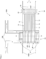
- Fig. 1 is a schematic conceptual view showing the configuration of a water recovery system to which one embodiment of a water recovery device of the present invention is applied.
- the water recovery system shown in Fig. 1 includes a combustion device 2000 and a water recovery device 1000.
- the combustion device 2000 is a device to combust fuel and emit exhaust gas including water vapor.
- Examples of the combustion device 2000 include a power engine to combust fuel and generate power (typically an engine), an electric-power generator to combust fuel and generate electric power, and a heater to combust fuel and generate hot air (hot wind) for a heater.
- Examples of the fuel include oil, coal and natural gas as well as a fuel made of their purified products or processed products. Such a fuel, when it is combusted, combines with oxygen in the air to generate water in the form of water vapor, and so exhaust gas including the water vapor will be emitted.
- the water recovery device 1000 includes a water generation unit 100, an exhaust gas pipe 200 and a water container 300.
- the exhaust gas pipe 200 is connected to the combustion device 2000, and defines an exhaust path of exhaust gas emitted from the combustion device 2000.
- a heat dissipation member 200a is preferably provided on the exhaust gas pipe 200, having a shape protruding toward the outside of the exhaust gas pipe 200, to let heat of the exhaust gas pipe 200 out.
- the water generation unit 100 generates water by cooling exhaust gas in the exhaust gas pipe 200 to condense water vapor in the exhaust gas.
- the configuration of the water generation unit 100 to generate water is described later.
- the water container 300 is provided along the exhaust path of the exhaust gas as stated above, and water generated in the water generation unit 100 drips into the water container 300 and is stored in the water container 300. Exhaust gas subjected to the condensing processing of water by the water generation unit 100 passes through the water container 300, and is finally emitted to the outside.
- the path of exhaust gas passing through the water container 300 is indicated with the downward solid arrow in the drawing toward the water container 300 and with the upward solid arrow in the drawing from the water container 300, and the exhaust gas emitted to the outside is indicated with the thick arrow to the right in the drawing.
- the water generation unit 100 includes an acoustic-wave generator 100A, a cold-heat generator 100B and a transmission pipe 100C.
- the acoustic-wave generator 100A generates acoustic waves by absorbing heat from the exhaust gas pipe 200 and converting the heat into acoustic-wave energy by means of a so-called thermoacoustic effect.
- This conversion into acoustic-wave energy is implemented by giving the absorbed heat to working fluid, which transmits acoustic waves by oscillating, to cause the working fluid to oscillate.
- the working fluid include gas having low viscosity and being less reactive, such as rare gas.
- the acoustic-wave generator 100A includes, as the configuration to implement conversion into acoustic-wave energy, a first heat/acoustic wave conversion component 1A and two heat exchangers 2A and 3A.
- the first heat/acoustic wave conversion component 1A includes thin tubular through holes (e.g., a plurality of cells described later) formed so as to penetrate through two end faces of the first heat/acoustic wave conversion component 1A, and these through holes are internally filled with the working fluid as stated above and are in communication with the transmission pipe 100C described later.
- the two heat exchangers 2A and 3A are provided having the first heat/acoustic wave conversion component 1A disposed therebetween so as to be close to both of the end faces of the first heat/acoustic wave conversion component 1A, respectively.
- the heat exchanger 2A that is one of the two heat exchangers 2A and 3A is in contact with the exhaust gas pipe 200, and the other heat exchanger 3A is separated from the exhaust gas pipe 200.
- the other heat exchanger 3A exchanges heat with the air so as to keep the temperature of the end face of the first heat/acoustic wave conversion component 1A close to the other heat exchanger 3A to a substantially constant low temperature in the range of 0 to 65°C in accordance with the air temperature.
- the one heat exchanger 2A as stated above transmits heat from the exhaust gas pipe 200 to the end face of the first heat/acoustic wave conversion component 1A close to the one heat exchanger 2A so as to keep this end face at a temperature relatively higher than that at the other end face (the end face on the other side close to the other heat exchanger 3A as stated above).
- thermoacoustic effect refers to such generation of acoustic waves due to the self-induced oscillation of working fluid resulting from heat. The following briefly describes this self-induced oscillation (a lot of documents describe the details, and JP 2012-237295 also provides the detailed descriptions thereon, for example).
- the thin tubular through holes in the first heat/acoustic wave conversion component 1A as stated above have an enough small hydraulic diameter HD to generate self-induced oscillation, and therefore self-induced oscillation occurs due to the temperature difference as stated above at the both end faces of the first heat/acoustic wave conversion component 1A.
- This self-induced oscillation generates acoustic waves that travel from the end face close to the heat exchanger 2A on the high-temperature side to the end face close to the heat exchanger 3A on the low-temperature side.
- the heat exchanger 3A is connected to the transmission pipe 100C described later, and the generated acoustic waves travel through this transmission pipe 100C toward a heat exchanger 2B of the cold-heat generator 100B described later.
- the transmission pipe 100C and the cold-heat generator 100B that are the elements of the water generation unit 100 other than the acoustic-wave generator 100A.
- the transmission pipe 100C is internally filled with the above-mentioned working fluid, and transmits acoustic waves generated by the acoustic-wave generator 100A via oscillations of this working fluid.
- the cold-heat generator 100B receives acoustic waves transmitted through the transmission pipe 100C, the cold-heat generator 100B generates cold heat by means of opposite mechanism (temperature gradient occurs at the through holes due to acoustic waves) of the thermoacoustic effect (acoustic waves are generated due to a temperature gradient of the through holes) as stated above, and supplies the cold heat to the exhaust gas pipe 200.
- the cold-heat generator 100B gives heat to the acoustic waves transmitted through the transmission pipe 100C so as to generate a temperature gradient, thereby creating a low-temperature state at a specific part, and supplying cold heat due to such a low-temperature state to the exhaust gas pipe 200.
- the cold-heat generator 100B includes a second heat/acoustic wave conversion component 1B and two heat exchangers 2B and 3B. As is evident from that this is based on the opposite mechanism of the thermoacoustic effect as stated above, similar configuration to that of the first heat/acoustic wave conversion component 1A and the two heat exchangers 2A and 3A in the acoustic-wave generator 100A as stated above can be used for the second heat/acoustic wave conversion component 1B and the two heat exchangers 2B and 3B.
- the second heat/acoustic wave conversion component 1B includes thin tubular through holes (e.g., a plurality of cells described later) formed so as to penetrate through two end faces of the second heat/acoustic wave conversion component 1B, and these through holes are internally filled with the working fluid as stated above and are in communication with the transmission pipe 100C described later. Acoustic waves transmitted through the transmission pipe 100C travel through these through holes.
- the heat exchanger 2B that is one of the two heat exchangers 2B and 3B is close to the end face of the second heat/acoustic wave conversion component 1B located upstream in the traveling direction of acoustic waves in these through holes, and is in contact with the exhaust gas pipe 200.
- the other heat exchanger 3B is close to the end face of the second heat/acoustic wave conversion component 1B located downstream in the traveling direction of acoustic waves, and exchanges heat with the air so as to keep the temperature of this downstream end face to a substantially constant low temperature in the range of 0 to 65°C in accordance with the air temperature.
- the one heat exchanger 2B as stated above is connected to the transmission pipe 100C, receives acoustic waves transmitted through the transmission pipe 100C and gives heat to the acoustic waves so that the temperature gradient corresponding to these acoustic waves is formed in the through holes.
- the one heat exchanger 2B and the end face of the second heat/acoustic wave conversion component 1B close to the one heat exchanger 2B have a relatively lower temperature than that of the other end face (downstream end face in the traveling direction of acoustic waves).
- the exhaust gas pipe 200 is cooled because the exhaust gas pipe 200 comes into contact with the one heat exchanger 2B in a low-temperature state. In other words, cold heat is supplied from the one heat exchanger 2B to the exhaust gas pipe 200.
- the heat exchanger 2A of the acoustic-wave generator 100A and the heat exchanger 2B of the cold-heat generator 100B which are the heat exchangers coming into contact with the exhaust gas pipe 200, are called the first heat exchanger 2A and the second heat exchanger 2B, respectively.
- the heat exchanger 3A of the acoustic-wave generator 100A and the heat exchanger 3B of the cold-heat generator 100B, which are the heat exchangers not coming into contact with the exhaust gas pipe 200, are called the third heat exchanger 3A and the fourth heat exchanger 3B, respectively.
- the second heat exchanger 2B has a function different from that of the first heat exchanger 2A, it can have the same configuration as that of the first heat exchanger 2A as stated above.
- the fourth heat exchanger 3B also can have the same configuration as that of the third heat exchanger 3A as stated above.
- the transmission pipe 100C is connected to both of the third heat exchanger 3A of the acoustic-wave generator 100A and the second heat exchanger 2B of the cold-heat generator 100B, and has a function to transmit acoustic waves generated at the acoustic-wave generator 100A to the cold-heat generator 100B.
- the transmission pipe 100C is connected to both of the fourth heat exchanger 3B of the cold-heat generator 100B and the first heat exchanger 2A of the acoustic-wave generator 100A as well, and as a result, a loop-like transmission path of acoustic waves is defined as a whole in the water generation unit 100 in Fig. 1 .
- the working fluid is confined in this loop-like transmission pipe 100C, and has a function to transmit acoustic waves, and the acoustic waves mainly travel through this loop-like transmission path counterclockwise in Fig. 1 .
- the present invention may include any path through which acoustic waves generated at the acoustic-wave generator 100A can be transmitted to the cold-heat generator 100B as the minimum requirement. That is, the present invention may include various forms of the transmission pipe that meet the minimum requirement as stated above and are well-known in the field of thermoacoustic effects, other than the loop-like form as in the transmission pipe 100C of Fig. 1 . These various forms that can be used are described later.
- the water recovery device 1000 enables effective recovery of water from exhaust gas in the exhaust gas pipe 200 by cooling the exhaust gas pipe 200 with the water generation unit 100 that makes use of the thermoacoustic effect in this way. Accordingly, water, which would be disposed to the air without the water generation unit 100, can be used as another purpose, by which water resource can be used effectively. Water can be used for various purposes. For instance, water can be used to cool, wash or humidify some devices or components (a specific example of the humidifying is described later).
- Further cooling by the water generation unit 100 is performed using heat of the exhaust gas pipe 200, which would be disposed without the water generation unit 100, and no energy is supplied from the outside other than this heat (e.g., circulation of cooling water separately performed is not required), and therefore effective use of energy resource also can be achieved at the same time.
- the following describes one specific example of the configuration of the acoustic-wave generator 100A in Fig. 1 .
- Fig. 2 is a schematic view showing one specific example of the configuration of the acoustic-wave generator 100A in Fig. 1 .
- the following describes one specific example of the configuration of the acoustic-wave generator 100A in Fig. 1 , in which the sane reference numerals are used for elements corresponding to the elements of Fig. 1 .
- the cold-heat generator 100B of Fig. 1 can have the same configuration as that of the acoustic-wave generator 100A
- the following specific example of the configuration of the acoustic-wave generator 100A corresponds to a specific example of the configuration of the cold-heat generator 100B as well.
- the acoustic-wave generator 100A of Fig. 2 includes the first heat/acoustic wave conversion component 1A, the first heat exchanger 2A and the third heat exchanger 3A, and additionally includes a metal member 32 and an interference member 12 as well.
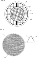
- the heat/acoustic wave conversion component 1A of Fig. 2 has a honeycomb structure in which a plurality of cells 14, each being a thin-tube like through hole, are defined by a partition wall 11.
- the word "cells" in the present specification refers to a through hole only that does not include the partition wall.
- Each cell 14 has a penetrating direction (an extending direction in which each cell 14 extends) that is the horizontal direction (lateral direction) of Fig. 2 , and is open at both end faces of an end face on the third heat exchanger 3A side and an end face of the first heat exchanger 2A side.
- the end face of the heat/acoustic wave conversion component 1 on the third heat exchanger 3A side is in contact with the metal member 32, and is opposed to the third heat exchanger 3A with the metal member 32 disposed therebetween.
- the metal member 32 since the metal member 32 plays a role for heat conduction as described later, the metal member 32 is preferably made of a material having large heat conductivity, which may be made of e.g., copper.
- the present invention may have a form of omitting the metal member 32, and in this case, a gap between the heat/acoustic wave conversion component 1 and the third heat exchanger 3A is as small as possible preferably.
- the metal member 32 is a member made of metal having a plate shape, at a center part of which a plurality of parallel slits (not illustrated) are formed, and FIG. 2 illustrates a side-face part (thickness part) of the plate shape only.
- the third heat exchanger 3A of Fig. 2 includes a mesh lamination body 30 formed by the lamination of a plurality of metal mesh plates (e.g., made of copper).
- the mesh lamination body 30 has a side face, at which a fin 31 is provided so as to protrude externally of the mesh lamination body 30.
- the fin 31 has a function of mediating heat exchange between the mesh lamination body 30 and the air so as to keep the temperature of the mesh lamination body 30 at a substantially constant low temperature in the range of 0 to 65°C in accordance with the air temperature. For instance, the fin 31 releases heat of the mesh lamination body 30 to the air, which can prevent the mesh lamination body 30 from reaching a high temperature.
- the temperature of the mesh lamination body 30 can be kept at such a low temperature, whereby the end face of the heat/acoustic wave conversion component 1 on the third heat exchanger 3A side close to the mesh lamination body 30 via the metal member 32 also can be kept at such a low temperature.
- the side face of the heat/acoustic wave conversion component 1 of Fig. 2 is surrounded by the interference member 12, and Fig. 2 schematically shows the cross section of the surrounding interference member 12 as two parts of the interference member 12 that sandwich the heat/acoustic wave conversion component 1 from both of upper and lower sides in the drawing.
- This interference member 12 has a function as a thermal insulator to avoid heat transmission via the surrounding environment outside of the heat/acoustic wave conversion component 1 between the end on the third heat exchanger 3A side of the heat/acoustic wave conversion component 1 and the end on the first heat exchanger 2A side of the heat/acoustic wave conversion component 1.
- the first heat exchanger 2A of Fig. 2 includes a honeycomb structure 20 for working fluid and a honeycomb structure 21 for exhaust gas.
- the honeycomb structure 20 for working fluid is a pillar-shaped honeycomb structure made of a metal material, and in the honeycomb structure 20 for working fluid, two or more cells 202, each extending in the horizontal direction (lateral direction) of Fig. 2 , are defined by a partition wall 201. These two or more cells 202 are in communication with the transmission pipe 100C and the plurality of cells 14 of the first heat/acoustic wave conversion component 1A, and are filled with working fluid.
- each of these two or more cells 202 has a sufficiently large hydraulic diameter, so that self-induced oscillations can be substantially ignored in the honeycomb structure 20 for working fluid. As shown in Fig.
- the honeycomb structure 20 for working fluid is close to the end face of the first heat/acoustic wave conversion component 1A (end face on the first heat exchanger 2A side), and has a function of receiving heat from the honeycomb structure 21 for exhaust gas described below and transmitting the heat to this end face (the end face on the first heat exchanger 2A side) to keep it at a high temperature (the state having a temperature higher than the temperature at the end face on the third heat exchanger 3A side).
- the metal honeycomb structure 20 for working fluid is preferably made of a material having large heat conductivity, which may be copper, for example.
- a member having a honeycomb structure instead of such a member having a honeycomb structure, a member having the configuration of a mesh lamination body formed by the lamination of a plurality of metal (e.g., copper) mesh plates may be used.
- the working fluid used preferably is less reactive with metals, such as rare gas.
- a honeycomb structure made of a ceramic material containing SiC (silicon carbide), which is not metal but has relatively large heat conductivity, as a main component may be used, instead of the honeycomb structure 20 for working fluid made of metal.
- the honeycomb structure 20 for working fluid also has a function as a traveling path of acoustic waves, in addition to heat conduction as stated above. That is, if some acoustic waves of the acoustic waves generated at the acoustic-wave generator 100A and traveling along the transmission pipe 100C in the direction of the thick arrow of Fig. 2 successively pass through the cold-heat generator 100B of Fig. 1 , such acoustic waves will reach the acoustic-wave generator 100A again after passing through the cold-heat generator 100B, which means that they will travel through two or more cells 202 in the honeycomb structure 20 for working fluid.
- honeycomb structure 21 for exhaust gas that is another element of the first heat exchanger 2A other than the honeycomb structure 20 for working fluid.
- the honeycomb structure 21 for exhaust gas is a hollow and round pillar-shaped (in other words, a cylindrical shape having a thickness in the radial direction) surrounding the honeycomb structure 20 for working fluid, and is made of a ceramic material containing SiC (silicon carbide) as a main component.
- the honeycomb structure 21 for exhaust gas surrounding the honeycomb structure 20 for working fluid is shown as separate parts above and below the honeycomb structure 20 for working fluid.
- a metal outer tube 23 and a metalized layer 22, which are described later referring to Fig. 3 are present between the honeycomb structure 20 for working fluid and the honeycomb structure 21 for exhaust gas, Fig. 2 omits them.
- Fig. 3 is a cross-sectional view of the first heat exchanger 2A taken along the line A-A of Fig. 2 .
- the honeycomb structure 21 for exhaust gas surrounds the honeycomb structure 20 for working fluid via the tube-like metalized layer 22 and the metal outer tube 23.
- the metal outer tube 23 is a tube-like metal member, into which the honeycomb structure 20 for working fluid is fitted, and has a function to hold the honeycomb structure 20 for working fluid from the circumference.
- the honeycomb structure 20 for working fluid itself has a metal circumferential wall surrounding its circumferential face, the metal outer tube 23 may be omitted.
- the metalized layer 22 is a layer formed by baking of metal, such as molybdenum and manganese, which is a layer to bond the metal outer tube 23 made of metal (when the metal outer tube 23 is omitted, the metal circumferential wall of the honeycomb structure 20 for working fluid) and the honeycomb structure 21 for exhaust gas made of ceramic.
- metal such as molybdenum and manganese
- the honeycomb structure 21 for exhaust has a configuration, including two or more cells extending in the horizontal direction (lateral direction) of Fig. 2 that are defined by a partition wall.
- the honeycomb structure 21 for exhaust gas is connected to the exhaust gas pipe 200, and exhaust gas flows into the honeycomb structure 21 for exhaust gas to give heat thereto and flows out from the honeycomb structure 21 for exhaust gas.
- the traveling path of exhaust gas is indicated with the dashed-dotted arrows, and as shown in this drawing, each cell of the honeycomb structure 21 for exhaust gas serves as the traveling path of exhaust gas flowing from the exhaust gas pipe 200.
- Heat transmitted from the exhaust gas to the honeycomb structure 21 for exhaust gas is transmitted to the circumferential face of the honeycomb structure 20 for working fluid that is surrounded by the honeycomb structure 21 for exhaust gas, and so the honeycomb structure 20 for working fluid is heated from the circumference.
- the heat received in this way by the honeycomb structure 20 for working fluid is used to keep the end face of the first heat/acoustic wave conversion component 1A on the first heat exchanger 2A side at a high-temperature state (a state higher than the temperature at the end face on the third heat exchanger 3A side).
- the honeycomb structure 21 for exhaust gas has a function of receiving heat from the exhaust gas pipe 200 and transmitting the heat to the honeycomb structure 20 for working fluid. Therefore, the honeycomb structure 20 for working fluid is desirably made of a material having high heat resistance as well as large heat conductivity, and a ceramic material containing SiC (silicon carbide) as a main component as stated above is a most suitable material to meet this demand. Actually ceramic materials have high heat resistance in general, and among such ceramic materials, a ceramic material containing SiC (silicon carbide) as a main component is a material that is known to have relatively high heat resistance.
- the honeycomb structure 21 for exhaust gas "containing SiC (silicon carbide) as a main component” means that SiC accounts for 50 mass% or more of the material of the honeycomb structure 21 for exhaust gas.
- the porosity of the honeycomb structure 21 for exhaust gas is preferably 0 to 10%. It is then preferable that the thickness of the partition wall 201 is 0.25 to 0.51 mm and the cell density is 15 to 62 cells/cm 2 .
- the ceramic material containing SiC as a main component include simple SiC as well as Si impregnated SiC, (Si+Al) impregnated SiC, metal composite SiC, recrystallized SiC, Si 3 N 4 and SiC.
- Si impregnated SiC and (Si+Al) impregnated SiC are preferable. This is because Si impregnated SiC has good heat conductivity and heat resistance, and has low porosity although it is a porous body and so is formed densely, and then it can realize relatively high strength as compared with SiC without impregnated Si.
- first heat exchanger 2A That is the description on the first heat exchanger 2A. The following describes the details of the configuration of the first heat/acoustic wave conversion component 1A of Fig. 2 .
- Fig. 4 is a cross-sectional view of the heat/acoustic wave conversion component 1 in a plane perpendicular to the penetrating direction of the cells 14 of the first heat/acoustic wave conversion component 1A of Fig. 2 .
- the first heat/acoustic wave conversion component 1A includes a plurality of cells 14, each being a thin-tube like through hole, that are defined by a partition wall 11, and the partition wall 11 as a whole is then surrounded with a circumferential wall 13 (not illustrated in Fig. 2 ).
- the circumferential wall 13 may be made of the same material as that of the partition wall 11.
- the hydraulic diameter HD of the cells 14 is one of the important factors to generate acoustic waves by self-induced oscillations, and the hydraulic diameter HD of the cells 14 in the first heat/acoustic wave conversion component 1A has a very small value of 0.4 mm or less.
- Such cells with a very small hydraulic diameter HD can realize a sufficient thermoacoustic effect from the first heat/acoustic wave conversion component 1A.
- the hydraulic diameter HD is larger than 0.4 mm, a small thermoacoustic effect only can be realized, and the amount of water recovered from the water recovery system of Fig. 1 , for example, is less to some extent.
- thermoacoustic effect it is advantageous to form as many as possible of the cells having a small hydraulic diameter HD as stated above.
- a larger open frontal area at the end faces of the first heat/acoustic wave conversion component 1A is more advantageous.
- the open frontal area of the first heat/acoustic wave conversion component 1A is high of 60% or more at each end face, from which a large thermoacoustic effect can be achieved. Conversely if the open frontal area is less than 60%, the number of cells contributing to the thermoacoustic effect is too small, and so a very large thermoacoustic effect cannot be achieved therefrom.
- the open frontal area of the first heat/acoustic wave conversion component 1A is limited to 93% or less. Actually if the open frontal area exceeds 93%, damage on the first heat/acoustic wave conversion component 1A due to impacts from acoustic waves generated or thermal distortion or warping (thermal stress) resulting from a temperature difference between both ends of the first heat/acoustic wave conversion component 1A cannot be ignored.
- the first heat/acoustic wave conversion component 1A has the open frontal area at the end faces of the first heat/acoustic wave conversion component 1A which is 60% or more and 93% or less, whereby adequate balance between a sufficient thermoacoustic effect and sufficient durability/strength can be achieved.
- the open frontal area of 80% or more and 93% or less is preferable in the open frontal area of 60% or more and 93% or less.
- the open frontal area can be obtained by taking an image of a cross section perpendicular to the penetrating direction by a microscope, and determining the material-part area S1 and the gap-part area S2 from the taken image of the cross section. Then the open frontal area can be obtained as S2/(S1+S2) based on S1 and S2.
- the cells 14 preferably have a cross-sectional shape that is perpendicular to the penetrating direction of the cells such that it is a polygonal shape whose corners are curved, and the corners of the shape preferably have a curvature radius of 0.02 mm or more and 0.1 mm or less.
- Fig. 4 shows a triangle with curved corners as an exemplary shape of the cells 14 in the enlarged view on the upper right side, where the curved corners of the triangle have the curvature radius of 0.02 mm or more and 0.1 mm or less.
- Such a curvature radius of 0.02 mm or more means a gently curved shape, and so the cells 14 can sufficiently resist an impact acting to crush the cells.
- thermoacoustic effect is set at 0.1 mm or less, whereby a high thermoacoustic effect also can be kept at the same time.
- the curvature radius at the corners of the cells 14 can be measured by taking an enlarged photo of the cells 14 in a cross section perpendicular to the penetrating direction and based on the cross-sectional shapes of the cells 14.
- the cells 14 may have a shape in a plane perpendicular to the penetrating direction of the cells 14 that is various polygons, such as triangles, quadrangles, pentagons and hexagons as well as ellipses (including a perfect circle shape), where triangles, quadrangles and hexagons and their combinations are preferable.
- triangular cells 14 are particularly preferable.
- Such triangular cells 14 are particularly preferable because, among various polygonal shapes and elliptical cell shapes, triangular cell shapes are the most suitable for the arrangement of a lot of cells while minimizing the thickness of the partition wall.
- the first heat/acoustic wave conversion component has a ratio HD/L of the hydraulic diameter HD as stated above to the length L that is 0.005 or more and less than 0.02. If HD/L is less than 0.005, the first heat/acoustic wave conversion component 1A is too long as compared with the hydraulic diameter HD. Then working fluid in each cell of the first heat/acoustic wave conversion component 1A will be less affected from a temperature difference between both ends of the heat/acoustic wave conversion component. In this case, heat exchange between the working fluid in each cell and the partition wall 11 is not sufficient and so a sufficient thermoacoustic effect cannot be obtained.
- the first heat/acoustic wave conversion component 1A is too short as compared with the hydraulic diameter HD. In this case, heat is transmitted through the partition wall 11 from the first heat exchanger 2A side to the third heat exchanger 3A side in the first heat/acoustic wave conversion component 1A before heat exchange between the working fluid in each cell and the partition wall 11 becomes sufficient. As a result, a sufficient thermoacoustic effect still cannot be obtained. Then, the first heat/acoustic wave conversion component 1A has the ratio HD/L of 0.005 or more and less than 0.02, and so heat exchange between the working fluid in each cell and the partition wall 11 is sufficient. As a result, the first heat/acoustic wave conversion component 1A can have a sufficient thermoacoustic effect.
- the materials making up the first heat/acoustic wave conversion component 1A, especially the materials making up the partition wall 11 have a ratio of thermal expansion at 20 to 800°C that is 6 ppm/K or less preferably.
- One of the methods to implement such a state of a low ratio of thermal expansion includes using a honeycomb structure made of cordierite that has a low ratio of thermal expansion among ceramic materials.
- a "honeycomb structure made of cordierite” refers to a honeycomb structure prepared using a cordierite forming raw material that is formulated to have a chemical composition in the range of 42 to 56 mass% silica, 30 to 45 mass% alumina and 12 to 16 mass% magnesia as a ceramic raw material to manufacture the honeycomb structure, which forms cordierite after firing.
- the ratio of thermal expansion can be measured, for example, by cutting out, from the first heat/acoustic wave conversion component 1A, a test piece that has a length of 10 mm or more along the penetrating direction of each cell and having an area of a cross section including the direction orthogonal to the penetrating direction that is 4 mm 2 or more and 100 mm 2 or less, and measuring the ratio of thermal expansion of this test piece in the penetrating direction using a differential thermal dilatometer using quartz as a reference comparative sample.
- Such a ratio of thermal expansion at 20 to 800°C of 6 ppm/K or less of the materials making up the partition wall 11 can suppress damage on the first heat/acoustic wave conversion component 1A when a temperature difference occurs at the both ends.
- a ratio of thermal expansion of 4 ppm/K or less is more preferable in the ratio of thermal expansion of 6 ppm/K or less.
- the following describes a method for manufacturing the water recovery device 1000 of Fig. 1 , to which a specific example of the acoustic-wave generator 100A of Fig. 2 is applied.
- a method for manufacturing the acoustic-wave generator 100A is described. Firstly a method for manufacturing the first heat/acoustic wave conversion component 1A is described below.
- Binder, surfactant, pore former, water and the like are added to a ceramic raw material to prepare a forming raw material.
- the ceramic raw material preferably includes one or two or more in combination of a cordierite forming raw material, a silicon carbide-cordierite based composite material, aluminum titanate, silicon carbide, a silicon-silicon carbide based composite material, alumina, mullite, spinel, lithium aluminum silicate, and Fe-Cr-Al based alloy.
- a cordierite forming raw material is preferable.
- the cordierite forming raw material is a ceramic raw material formulated to have a chemical composition in the range of 42 to 56 mass% silica, 30 to 45 mass% alumina and 12 to 16 mass% magnesia, and that forms cordierite after firing.
- the ceramic raw material preferably is contained to be 40 to 90 mass% with reference to the forming raw material as a whole.
- Exemplary binder includes methyl cellulose, hydroxypropoxyl cellulose, hydroxyethylcellulose, carboxymethylcellulose, or polyvinyl alcohol. Among them, methyl cellulose and hydroxypropoxyl cellulose are preferably used together.
- the content of the binder is preferably 2 to 20 mass% with reference to the forming raw material as a whole.
- the content of water is preferably 7 to 45 mass% with reference to the forming raw material as a whole.
- Exemplary surfactant used includes ethylene glycol, dextrin, fatty acid soap, or polyalcohol. They may be used alone or in combination of two or more types. The content of the surfactant is preferably 5 mass% or less with reference to the forming raw material as a whole.
- Exemplary pore former includes starch, foamable resin, water absorbable resin or silica gel.
- a kneaded material is prepared by kneading the forming raw material.
- a method for preparing a kneaded material by kneading the forming raw material is not limited especially. For instance, a kneader or a vacuum pugmill may be used for this purpose.
- the kneaded material is extruded, whereby a honeycomb formed body including a partition wall defining a plurality of cells is prepared.
- a die having a shape in accordance with the hydraulic diameter of each cell, the open frontal area, the shape of the first heat/acoustic wave conversion component 1A, the cell shape, and the period of the cells as stated above is preferably used.
- a preferable material of the die is cemented carbide having wear resistance. Values of the hydraulic diameter of each cell, the open frontal area, or the like of the honeycomb formed body are determined preferably while considering contraction generated during drying and firing described later as well.
- the first heat/acoustic wave conversion component 1A having a very small hydraulic diameter of each cell and having a large open frontal area (having large cell density) as stated above to exert a large thermoacoustic effect cannot be manufactured by simply using an extrusion method as it is (i.e., by simply executing a similar manufacturing method using a different die to form high-density pores) that is used for a conventional honeycomb structure to load catalyst for exhaust purification, which is free from such constraints, due to the following two problems.
- the first problem is that, during extrusion, kneaded material extruded at a high temperature adheres to the holes in a forming die, which easily generates clogging. This problem is mentioned also by Patent Document, JP-A-2012-237295 as stated above in paragraph [0021].
- the second problem is that a die used for a honeycomb structure as in the first heat/acoustic wave conversion component 1A as stated above having a very small hydraulic diameter of each cell and having a large open frontal area (having large cell density) inevitably includes a very thin and minute part (typically a part of about 0.3 mm in thickness). Then, such a minute part often is damaged (e.g., is torn) by viscous friction during kneaded material extrusion.
- the manufacturing method of the first heat/acoustic wave conversion component 1A as stated above has the following configuration to solve these two problems.
- a kneaded material is extruded using another die (hereinafter called a dummy die) having a very small thickness of ribs that is 0.04 mm or more and 0.09 mm or less.
- the "thickness of ribs” here refers to the thickness of the partition wall of the honeycomb formed body, and means a slit width of the die. Each slit is a hole to discharge the kneaded material and is to determine the shape of each partition wall part at the honeycomb structure to be manufactured. In the following, the "thickness of ribs" means the slit width.
- the second problem is solved by reducing viscosity of the kneaded material used for extrusion greatly as compared with the viscosity of a kneaded material used for a conventional honeycomb structure to load catalyst for exhaust purification so as to reduce the viscous friction while keeping the range of a shape-holding property (i.e. the shape of the formed body is not distorted) of the formed body of the first heat/acoustic wave conversion component 1A during extrusion.
- a shape-holding property i.e. the shape of the formed body is not distorted
- the ratio of water in the kneaded material has to be more strictly controlled than in the manufacturing of a conventional honeycomb structure to load catalyst for exhaust purification (i.e., keeping an error between the control target of the water ratio and the actual water ratio in a very narrow range).
- the ratio of water in the kneaded material is 40 to 42 parts by mass with reference to 100 parts by mass of the kneaded material solid component that is used to manufacture the first heat/acoustic wave conversion component 1A, while the ratio of water in the kneaded material is 25 to 35 parts by mass with reference to 100 parts by mass of the kneaded material solid component that is used to manufacture a conventional honeycomb structure to load catalyst for exhaust purification.
- the ratio of water in the kneaded material increases, then viscosity of the kneaded material decreases and adequate fluctuations occur in the shape of the formed body of the first heat/acoustic wave conversion component 1A. This leads to another advantageous effect that self-induced oscillations of acoustic waves likely occur.
- a method for drying is not limited especially, and exemplary methods include an electromagnetic wave heating method such as microwave heat-drying and highfrequency induction heating drying and an external heating method such as hot air drying and superheated steam drying. After a certain amount of water may be dried by an electromagnetic wave heating method, followed by an external heating method to dry the remaining water. In this case, it is preferable that, after 30 to 90 mass% of water with reference to the water amount before drying is removed by an electromagnetic heating method, followed by an external heating method to reduce water amount to 3 mass% or less.
- a preferable electromagnetic wave heating method includes induction heating drying, and a preferable external heating method includes hot air drying.
- exemplary method includes a method using a circular saw cutter.
- this honeycomb formed body is fired. It is preferable to perform calcination before firing to remove the binder and the like.
- the calcination is preferably performed at 400 to 500°C for 0.5 to 20 hours in the ambient atmosphere.
- a method for calcination or firing (main firing) is not limited especially, and they may be performed using an electric furnace, a gas furnace, or the like.
- the firing (main firing) conditions it is preferably heated at 1,300 to 1,500°C for 1 to 20 hours in an inert atmosphere of nitrogen, argon, or the like when a silicon-silicon carbide based composite material is used, for example.
- an oxide-based material is used, it is preferably heated at 1,300 to 1,500°C for 1 to 20 hours in an oxygen atmosphere.
- the circumferential part of the honeycomb formed body after firing is cut as needed to correct the shape.
- an outer coating material is applied to the circumferential face of the honeycomb formed body after cutting, followed by drying, whereby a circumferential wall 13 is formed.
- the outer coating material used may be slurry, for example, which is prepared by adding an additive such as organic binder, foamable resin or dispersing agent to a raw material including inorganic particles and colloidal oxide, to which water is added, followed by kneading.
- exemplary inorganic particles include particles made of a ceramic material containing one or two or more in combination of cordierite, alumina, aluminum titanate, silicon carbide, silicon nitride, mullite, zirconia, zirconium phosphate and titania, or particles of Fe-Cr-Al-based metal, nickel-based metal and silicon (metal silicon)-silicon carbide based composite materials.
- Exemplary colloidal oxide includes silica sol and alumina sol.
- a method for applying the outer coating material is not limited especially, and for example, the coating material may be coated with a rubber spatula, for example, while rotating the honeycomb formed body after cutting on a wheel.
- the first heat/acoustic wave conversion component 1A is finally completed.
- the honeycomb structure 21 for exhaust gas in the first heat exchanger 2A of Fig. 2 can be manufactured by a manufacturing method similar to the method for manufacturing the first heat/acoustic wave conversion component 1A of Fig. 4 as stated above, other than that mixture of carbon powder (e.g., graphite powder) with SiC powder is used as the ceramic raw material, that a die suitable for a honeycomb formed body having a relatively large hydraulic diameter HD of cells is used as the die for extrusion, and that, in order to achieve the shape of a hollow and round pillar-shape (in other words, a cylindrical shape having a thickness), cutting is performed so as to have this shape after firing or a die leading to this shape is used during forming processing in the method for manufacturing the monolithic first heat/acoustic wave conversion component 1A of Fig. 4 as stated above.
- a manufacturing method similar to the method for manufacturing the first heat/acoustic wave conversion component 1A of Fig. 4 as stated above other than that mixture of carbon powder (e.g.
- this honeycomb structure 21 for exhaust gas for example, to manufacture the honeycomb structure 20 for working fluid including a Si impregnated SiC composite material as a main component, it is preferable that a kneaded material prepared by mixing SiC powder with carbon powder and kneading for adjustment is formed to be a honeycomb formed body, then drying and firing processing are performed thereto, and then molten silicon (Si) is impregnated in this honeycomb formed body.
- a kneaded material prepared by mixing SiC powder with carbon powder and kneading for adjustment is formed to be a honeycomb formed body, then drying and firing processing are performed thereto, and then molten silicon (Si) is impregnated in this honeycomb formed body.
- Such processing can form a configuration where coagulation of metal Si (metal silicon) surrounds the surface of SiC particles after the firing processing, and SiC particles are mutually bonded via metal Si.
- Such a configuration can achieve high heat durability and heat conductivity in spite of the dense configuration
- metals such as Al, Ni, Cu, Ag, Be, Mg, and Ti may be used for impregnation.
- coagulation of metal Si (metal silicon) and other metals used for impregnation surrounds the surface of SiC particles, and SiC particles are mutually bonded via metal Si and other metals used for impregnation in the formed configuration.
- Such a configuration also can achieve high heat durability and heat conductivity in spite of the dense configuration with small porosity.
- the honeycomb structure 20 for working fluid in the first heat exchanger 2A of Fig. 2 can be manufactured by a conventional manufacturing method that is used to manufacture a metal honeycomb structure, such as method for forming a honeycomb structure using a mold or a method for forming a honeycomb structure by cutting.
- the metal outer tube 23 and the metalized layer 22 also can be manufactured by a conventional method.
- the third heat exchanger 3A of Fig. 2 can be manufactured using a conventionally known method for manufacturing a heat exchanger as it is.
- the cold-heat generator 100B can have a configuration similar to the acoustic-wave generator 100A as stated above, and so it can be manufactured similarly to the acoustic-wave generator 100A as stated above.
- the transmission pipe 100C can be manufactured by forming a material with high durability into an annular shape (note here that an annular shape with a part thereof missing so as to enable connection with the acoustic-wave generator 100A and the cold-heat generator 100B).
- the material with high durability is not limited especially, and examples thereof include metal such as iron, a hard plastic material, hardened glass, as well as a ceramic material (e.g., those listed for the material of the first heat/acoustic wave conversion component 1A as stated above).
- the exhaust gas pipe 200 can be manufactured by forming a material with high heat resistance to be in a form connectable to the water generation unit 100 and the water container 300 as shown in Fig. 1 .
- the material with high heat resistance is not limited especially, and specific examples thereof include high heat-resistance stainless steel, metal such as iron or copper, as well as a ceramic material (e.g., those listed for the material of the first heat/acoustic wave conversion component 1A of Fig. 4 or for the honeycomb structure 20 for working fluid as stated above).
- a container of a size in accordance with the size of the water recovery device 1000 or the amount of water to be recovered can be used.
- This container may be manufactured using an appropriate material, such as metal, a plastic material or ceramic, or a commercially available container may be selected for use as needed.
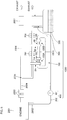
- Fig. 5 is a schematic conceptual view showing another water recovery system to which the water recovery device 1000 of Fig. 1 is applied.
- the water recovery system of Fig. 5 includes an engine 2001 that generates power through explosion power (expansion power) which is obtained by mixing evaporated gasoline and air to highly compress the mixture gas, and by igniting this compressed gas. Exhaust gas generated during the generation of this power is emitted through a first exhaust gas pipe 2004.
- explosion power expansion power
- Exhaust gas generated during the generation of this power is emitted through a first exhaust gas pipe 2004.
- hydrogen (hydrogen atoms) in the evaporated gasoline and oxygen in the air are combined to generate water, and so the water is included in the exhaust gas in the form of water vapor.
- Exhaust gas undergoes purification processing by two three-way catalytic converters 2003 provided on the first exhaust gas pipe 2004, and is separated at a branch 2005 to be along two different exhaust paths for emission.
- One of the exhaust paths is an exhaust path defined by a second exhaust gas pipe 2006, where much of the exhaust gas (50 to 99 volume% as described later) passes through this second exhaust gas pipe 2006, which is then emitted externally through a muffler 2007 provided on the second exhaust gas pipe 2006.
- one end of the exhaust gas pipe 200 of the water recovery device 1000 described in Fig. 1 is connected to the branch 2005, and this exhaust gas pipe 200 defines another exhaust path different from the second exhaust gas pipe 2006 as stated above.
- this exhaust gas pipe 200 may be called a bypass pipe 200.
- a part of exhaust gas emitted from the engine 2001 is bypassed, and water is recovered from the bypassed exhaust gas.
- Such recovery of water is performed using the water generation unit 100, the exhaust gas pipe 200 and the water container 300 described in Fig. 1 , and so their duplicated descriptions are omitted.
- the specific example described in Fig. 2 can be used for the water generation unit 100.
- an injector 2002 is provided at the engine 2001 so as to inject water to mixture gas of the evaporated gasoline and air.
- a water recovery device 1000' further includes, in addition to the water generation unit 100, the exhaust gas pipe 200 and the water container 300 as stated above, a water supply mechanism 400 to supply water to the injector 2002.
- the water supply mechanism 400 has a pump 401 and a water supply pipe 402, and is able to pump up water in the water container 300 by the pump 401 and send the pumped water to the injector 2002 via the water supply pipe 402. In this way, the water recovery device 1000' can effectively use water recovered from exhaust gas as water to suppress abnormal combustion.
- exhaust gas from a gasoline engine typically includes a lot of water, and if the entire exhaust gas is a target from which water is to be recovered, the water recovery device will be large in size because it has to store a lot of water.
- the water recovery system of Fig. 5 recovers water in the bypassed exhaust gas only, whereby its water recover device can have an appropriate size, instead of such a large size.
- the bypass pipe 200 define an exhaust path for 1 to 50 volume % of exhaust gas of the entire exhaust gas. If it is less than 1 volume%, the amount of recovered water is too small, and if it exceeds 50 volume%, the amount of recovered water is too much, which means difficulty to avoid a large-sized water recovery device 1000.
- the water recovery device 1000' of Fig. 5 can be manufactured by combining the water supply mechanism 400 including the pump 401 and the water supply pipe 402 with the method for manufacturing the water recovery device 1000 of Fig. 1 as stated above.
- a conventionally known water circulation system e.g., a commercially available water circulation device can be used as it is.
- the third heat exchanger 3A and the fourth heat exchanger 3B of the water generation unit 100 which do not come into contact with the exhaust gas pipe 200, perform heat exchange with air.
- the present invention may have another form in which heat exchange is performed with circulating water at ambient temperature. In this case, although there are drawbacks, compared with heat exchange with air, that power and energy for water circulation are required and size of the water recovery device is increased, the temperature at an end face of each heat/acoustic wave conversion component close to each of the above two heat exchangers is more stable and can be kept at a constant temperature around an ambient temperature.
- the water recovery device 1000 of Fig. 1 and the water recovery device 1000' of Fig. 5 as described above include a loop-shaped transmission pipe 100C.
- the transmission pipe of the present invention may have another form as long as it meets the minimum requirement that acoustic waves generated at the acoustic-wave generator 100A are transmitted to the cold-heat generator 100B.
- various forms that are well known in the field of thermoacoustic effect can be used, other than a loop-like form.
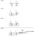
- Fig. 6 to Fig. 9 show variations of the transmission pipe 100C in the water generation unit 100 of the water recovery device 1000 of Fig. 1 or the water recovery device 1000' of Fig. 5 .
- Fig. 6 shows a generally straight-line shaped transmission pipe
- Fig. 7 shows a transmission pipe that has a loop shape at around the acoustic-wave generator 100A only, and a part around the cold-heat generator 100B has a straight-line shape.
- the transmission pipe is open on the right of the cold-heat generator 100B in the drawings, and air (atmosphere) is used as the working fluid.
- Fig. 8 shows a transmission pipe including separate loop shapes around the acoustic-wave generator 100A and the cold-heat generator 100B, and in this form no opening is present, and air does not flow into or out from the transmission pipe. Therefore, a specific type of air, such as less reactive rare gas, can be used as the working fluid.
- Fig. 9 shows an example, in which a sound/electricity converter 2008 is connected to the open end of the transmission pipe in the form of Fig. 7 .
- energy of acoustic waves passing through the cold-heat generator 100B is converted into electricity at the sound/electricity converter 2008, and so the energy can be effectively used in the form of electricity.
- a microphone can be used, for example.
- the energy can be used as a certain power source (the acoustic-wave energy is allowed to collide with a fan so as to generate a rotating force of the fan, for example).
- an engine gasoline having displacement of 2 L was used.
- As the working fluid helium gas of 1 MPa in pressure was used, and as the transmission pipe of the working fluid, a transmission pipe having a diameter of 40 mm was used.
- a cordierite honeycomb structure was used, having a round pillar-shape of 40 mm in diameter and 60 mm in length, where each cell had a hydraulic diameter of 0.3 mm and an open frontal area at end faces was 74%.
- Cordierite forming raw material was used as the ceramic raw material, and 1 part by mass of pore former, 35 parts by mass of dispersing medium, 6 parts by mass of organic binder, and 0.5 parts by mass of dispersing agent were added to 100 parts by mass of the cordierite raw material, followed by mixing and kneading to prepare a kneaded material.
- the cordierite raw material used included 38.9 parts by mass of talc of 3 ⁇ m in average particle diameter, 40.7 parts by mass of kaolin of 1 ⁇ m in average particle diameter, 5.9 parts by mass of alumina of 0.3 ⁇ m in average particle diameter, and 11.5 parts by mass of boehmite of 0.5 ⁇ m in average particle diameter.
- the average particle diameter refers to a median diameter (d50) in the particle distribution of each raw material.
- Water was used as the dispersing medium. Hydroxypropylmethylcellulose was used as the organic binder. Ethylene glycol was used as the dispersing agent.
- the thus obtained kneaded material was extruded using a die, so that a honeycomb formed body including triangular cells and having a circular overall shape was prepared.
- the kneaded material was extruded using a dummy die of about 0.07 mm in rib thickness as stated above. Then, using the kneaded material after the extrusion using this dummy die, extrusion using the real die was executed.
- the ratio of water in the kneaded material used for the extrusion using the real die was strictly controlled in the kneaded material component so that it was 41 parts by mass (error was within ⁇ 1 part by mass) with reference to 100 parts by mass of the kneaded material solid component.
- this honeycomb formed body was dried by a microwave dryer, and further was dried completely by a hot-air drier, and then both end faces of the honeycomb formed body were cut so as to adjust the length of the honeycomb formed body in the cell penetrating direction.
- Such a honeycomb formed body was dried by a hot-air drier, and then was fired at 1,445°C for 5 hours.
- the circumferential part of the honeycomb formed body after the firing step was cut as needed to correct the shape to be a round pillar-shape.
- an outer coating material was applied to the circumferential face of the honeycomb formed body after cutting, followed by drying, whereby a circumferential wall was formed.
- the outer coating material was slurry prepared by adding organic binder, foamable resin and dispersing agent to a raw material including cordierite particles and silica sol, to which water was added and kneaded.
- the coating material was coated with a rubber spatula, for example, while rotating the honeycomb formed body after cutting on a wheel.
- a heat/acoustic wave conversion component was completed.
- the hydraulic diameter HD of the cells in a plane perpendicular (perpendicular plane) to the cell penetrating direction and the open frontal area at the end faces of the heat/acoustic wave conversion component were measured.
- the hydraulic diameter HD of the cells was 0.3 mm, and the open frontal area at the end faces of the heat/acoustic wave conversion component was 74%.
- the open frontal area was obtained by taking an image of the cross section in the perpendicular plane by a microscope, and finding the material-part area S1 and the gap-part area S2 from the image taken of the cross section. Then the open frontal area was obtained as S2/(S1+S2) based on S1 and S2. Note that the open frontal area at the cross section as a whole is considered to be equal to the open frontal area at the end face, and then the open frontal area at the cross section as a whole is considered as the open frontal area at the end face.
- each heat/acoustic wave conversion component in this example.
- the elements other than the heat/acoustic wave conversion component e.g., the heat exchangers and the transmission pipe were prepared appropriately so as to suit for the size or the shape of the heat/acoustic wave conversion component as stated above.
- the device was operated under the control condition that the number of revolutions of the engine was set at 2,000 (revolutions per minute) and the temperature at around the exhaust gas outlet of the two three-way catalytic converters was 600°C.
- the amount of water injected by the injector i.e., the amount of water recovered by the water recovery device was 0.8 [Kg/hour].
- thermoacoustic effect can recover water from exhaust gas of an engine effectively.
- thermoacoustic effect obtained from a honeycomb structure including each cell having the hydraulic diameter of 0.4 mm or less and the open frontal area of 60% or more and 93% or less, i.e., having a very small hydraulic diameter and a large open frontal area (having large cell density), by way of the experiment using the heat/acoustic wave conversion components of the following honeycomb structures ⁇ 1> to ⁇ 4>.
- Honeycomb structure ⁇ 1> was a cordierite honeycomb structure that was used as a heat/acoustic wave conversion component in the above-stated example, and as stated above, this honeycomb structure ⁇ 1> had the hydraulic diameter HD of cells that was 0.3 mm, and the open frontal area at the end faces of the honeycomb structure ⁇ 1> that was 74%.
- the cold-heat generator 100B of the water generation unit 100 in Fig. 1 was removed, and a microphone was connected to one end of the transmission pipe 100C on the acoustic-wave generator 100A side that was connected to the cold-heat generator 100B.
- Honeycomb structure ⁇ 1> was assembled as the heat/acoustic wave conversion component 1 in the acoustic-wave generator 100A.
- exhaust gas of an automobile at about 500°C was allowed to flow into there for 10 minutes, and the temperature of the exhaust gas flowing out whose temperature fell to some extent was measured. Based on a temperature change at this time, the amount of heat flowing into this system was calculated.
- the temperature at the end face of Honeycomb structure ⁇ 1> on the first heat exchanger side was kept at 500°C substantially.
- the temperature at the end face on the third heat exchanger side on the opposite side was kept at 60°C substantially due to heat exchange with air.
- measurement was performed using the microphone as stated above as to what degree of electric power was generated from acoustic waves by a thermoacoustic effect due to the temperature difference at this Honeycomb structure ⁇ 1>.
- a measurement value of the electric power amount was divided by the energy conversion efficiency (efficiency to convert acoustic-wave energy into electric power) of the microphone known beforehand, whereby an estimated value of acoustic-wave energy was obtained.
- Honeycomb structure ⁇ 2> and Honeycomb structure ⁇ 3> were manufactured by the same manufacturing method as that of Honeycomb structure ⁇ 1> other than that a different die was used for extrusion, whereby these honeycomb structures were different from Honeycomb structure ⁇ 1> only in the value of hydraulic diameter HD of the cells among the two types of parameters as stated above.
- Honeycomb structures ⁇ 4> to ⁇ 7> were manufactured by the same manufacturing method as that of Honeycomb structure ⁇ 1> other than that a different die was used for extrusion, whereby these honeycomb structures were different from Honeycomb structure ⁇ 1> only in the value of open frontal area at the end faces (the same as the open frontal area in the plane perpendicular to the cell penetrating direction).
- Table 1 shows the experimental results on Honeycomb structures ⁇ 1> to ⁇ 7> as described above, together with the values of parameters.
- Cell hydraulic diameter HD (mm) Open frontal area at end face (%) Energy conversion efficiency (%) Honeycomb structure ⁇ 1> 0.30 74 18.3 Honeycomb structure ⁇ 2> 0.40 74 13.8 Honeycomb structure ⁇ 3> 0.45 74 10.0 Honeycomb structure ⁇ 4> 0.30 55 8.8 Honeycomb structure ⁇ 5> 0.30 60 17.6 Honeycomb structure ⁇ 6> 0.30 93 20.0 Honeycomb structure ⁇ 7> 0.30 95 -
- the open frontal area at the end face of a heat/acoustic wave conversion component that is 60% or more and 93% or less is required to have a large thermoacoustic effect achieved and to avoid damage.
- the present invention is useful to make use of water vapor included in exhaust gas of a combustion device.
Landscapes
- Engineering & Computer Science (AREA)
- Chemical & Material Sciences (AREA)
- General Engineering & Computer Science (AREA)
- Mechanical Engineering (AREA)
- Combustion & Propulsion (AREA)
- Water Supply & Treatment (AREA)
- Thermal Sciences (AREA)
- Physics & Mathematics (AREA)
- Oil, Petroleum & Natural Gas (AREA)
- Chemical Kinetics & Catalysis (AREA)
- General Chemical & Material Sciences (AREA)
- Analytical Chemistry (AREA)
- Public Health (AREA)
- Health & Medical Sciences (AREA)
- Heat-Exchange Devices With Radiators And Conduit Assemblies (AREA)
- Exhaust Silencers (AREA)
Applications Claiming Priority (1)
| Application Number | Priority Date | Filing Date | Title |
|---|---|---|---|
| JP2015098473A JP6467284B2 (ja) | 2015-05-13 | 2015-05-13 | 水回収装置 |
Publications (2)
| Publication Number | Publication Date |
|---|---|
| EP3093474A1 EP3093474A1 (en) | 2016-11-16 |
| EP3093474B1 true EP3093474B1 (en) | 2020-01-08 |
Family
ID=56108453
Family Applications (1)
| Application Number | Title | Priority Date | Filing Date |
|---|---|---|---|
| EP16166306.7A Active EP3093474B1 (en) | 2015-05-13 | 2016-04-21 | Water recovery device |
Country Status (3)
| Country | Link |
|---|---|
| US (1) | US9739187B2 (enExample) |
| EP (1) | EP3093474B1 (enExample) |
| JP (1) | JP6467284B2 (enExample) |
Families Citing this family (10)
| Publication number | Priority date | Publication date | Assignee | Title |
|---|---|---|---|---|
| US10041747B2 (en) * | 2010-09-22 | 2018-08-07 | Raytheon Company | Heat exchanger with a glass body |
| JP6632029B2 (ja) * | 2016-06-09 | 2020-01-15 | 中央精機株式会社 | 熱音響エンジン、及び、熱音響エンジンの設計方法 |
| TWI602778B (zh) * | 2016-11-24 | 2017-10-21 | 財團法人工業技術研究院 | 二氧化碳捕獲裝置與系統及其方法 |
| JP2019086176A (ja) * | 2017-11-02 | 2019-06-06 | 株式会社Soken | 工業炉 |
| JP2019210647A (ja) * | 2018-06-01 | 2019-12-12 | 株式会社Soken | 水製造装置 |
| CN110201499A (zh) * | 2018-11-06 | 2019-09-06 | 深圳市贝腾科技有限公司 | 热交换装置及冷冻干燥机 |
| JP7280730B2 (ja) | 2019-03-25 | 2023-05-24 | 日本碍子株式会社 | 排ガスフィルタの再生方法及び排ガスフィルタ含浸システム |
| US11118490B2 (en) * | 2020-01-24 | 2021-09-14 | Caterpillar Inc. | Machine system for co-production of electrical power and water and method of operating same |
| AT526089B1 (de) * | 2022-04-26 | 2023-11-15 | Avl List Gmbh | Wasserstoffbetriebene brennkraftmaschine |
| US20240051861A1 (en) * | 2022-08-09 | 2024-02-15 | Owens-Brockway Glass Container Inc. | Hydrogen-fueled submerged combustion melter and glass melting system including the same |
Family Cites Families (13)
| Publication number | Priority date | Publication date | Assignee | Title |
|---|---|---|---|---|
| JPH01134021A (ja) * | 1987-11-17 | 1989-05-26 | Daiwa Kogyo Kk | 冷却装置付き消音器 |
| KR100402957B1 (ko) * | 2000-12-05 | 2003-10-30 | 주 철 이 | 내연기관엔진 가지배기관과 냉각날개가 구비된 머플 시스템 |
| US7488412B2 (en) | 2001-07-13 | 2009-02-10 | Ngk Insulators, Ltd. | Honeycomb structural body, honeycomb filter, and method of manufacturing the structural body and the filter |
| US7040088B2 (en) * | 2002-12-20 | 2006-05-09 | Raymond Paul Covit | Diesel engine exhaust purification system |
| JP2005233485A (ja) | 2004-02-18 | 2005-09-02 | Toyota Motor Corp | 内燃機関の冷却装置 |
| JP4882699B2 (ja) * | 2005-12-20 | 2012-02-22 | 株式会社デンソー | 排熱回収装置 |
| JP2009008318A (ja) * | 2007-06-27 | 2009-01-15 | Denso Corp | 排熱回収装置 |
| FR2926325A3 (fr) | 2008-01-15 | 2009-07-17 | Renault Sas | Systeme d'injection d'eau dans une chambre de combustion d'un cylindre de moteur a combustion interne. |
| US8425666B2 (en) * | 2009-01-14 | 2013-04-23 | Purestream Technology, Llc | Back pressure-matched, integrated, environmental-remediation apparatus and method |
| JP2012154251A (ja) * | 2011-01-26 | 2012-08-16 | Honda Motor Co Ltd | 排気消音装置 |
| JP5616287B2 (ja) | 2011-05-13 | 2014-10-29 | 日本電信電話株式会社 | 熱音響装置用スタックおよび熱音響装置用スタックの製造方法 |
| JP2013199882A (ja) * | 2012-03-26 | 2013-10-03 | Hino Motors Ltd | 内燃機関 |
| EP3018332B1 (en) | 2013-06-28 | 2017-07-26 | Toyota Jidosha Kabushiki Kaisha | Condensed water processing device of internal combustion engine |
-
2015
- 2015-05-13 JP JP2015098473A patent/JP6467284B2/ja active Active
-
2016
- 2016-04-11 US US15/095,377 patent/US9739187B2/en active Active
- 2016-04-21 EP EP16166306.7A patent/EP3093474B1/en active Active
Non-Patent Citations (1)
| Title |
|---|
| None * |
Also Published As
| Publication number | Publication date |
|---|---|
| US20160333757A1 (en) | 2016-11-17 |
| EP3093474A1 (en) | 2016-11-16 |
| US9739187B2 (en) | 2017-08-22 |
| JP2016211517A (ja) | 2016-12-15 |
| JP6467284B2 (ja) | 2019-02-13 |
Similar Documents
| Publication | Publication Date | Title |
|---|---|---|
| EP3093474B1 (en) | Water recovery device | |
| CN101929676B (zh) | 一种催化多孔介质燃烧器 | |
| JP5756467B2 (ja) | 汚染制御装置のための低剪断取付けマット | |
| US9759157B2 (en) | Heat/acoustic wave conversion unit | |
| US9163538B2 (en) | Fine particle collecting filter | |
| WO2003078026A1 (en) | Ceramic filter for exhaust emission control | |
| WO2003082771A1 (en) | Porous material and method for production thereof | |
| US9869303B2 (en) | Heat/acoustic wave conversion component and heat/acoustic wave conversion unit | |
| US9759201B2 (en) | Heat/acoustic wave conversion component and heat/acoustic wave conversion unit | |
| Cutler et al. | A new high temperature ceramic material for diesel particulate filter applications | |
| WO2002044105A1 (en) | Porous sound absorbing material and method of manufacturing the material | |
| US9777714B2 (en) | Heat/acoustic wave conversion component and heat/acoustic wave conversion unit | |
| US20160090970A1 (en) | Heat/acoustic wave conversion component and heat/acoustic wave conversion unit | |
| US9976467B2 (en) | Exhaust system | |
| EP2998576B1 (en) | Heat/acoustic wave conversion component and heat/acoustic wave conversion unit | |
| US20240368042A1 (en) | Ceramic honeycomb structure and its production method | |
| JP6535530B2 (ja) | ハニカム構造体の製造方法 | |
| CN106524143B (zh) | 一种应用于微热光电系统的燃烧器 | |
| CN206191585U (zh) | 一种应用于微热光电系统的燃烧器 | |
| JP2023172734A (ja) | 潜熱蓄熱体及び潜熱蓄熱体の製造方法 | |
| JP2009011994A (ja) | セラミックフィルター及びその製造方法 | |
| JP2004294025A (ja) | 熱交換器 | |
| JP6622496B2 (ja) | 拡散部材、排ガス浄化装置及び排ガス浄化装置における拡散部材の使用 | |
| JP2001334154A (ja) | コージェライト質セラミックハニカム構造触媒用担体及びその製造方法 | |
| CN107051561A (zh) | 一种耐高温抗氧化镍基蜂窝结构载体的制备方法 |
Legal Events
| Date | Code | Title | Description |
|---|---|---|---|
| PUAI | Public reference made under article 153(3) epc to a published international application that has entered the european phase |
Free format text: ORIGINAL CODE: 0009012 |
|
| AK | Designated contracting states |
Kind code of ref document: A1 Designated state(s): AL AT BE BG CH CY CZ DE DK EE ES FI FR GB GR HR HU IE IS IT LI LT LU LV MC MK MT NL NO PL PT RO RS SE SI SK SM TR |
|
| AX | Request for extension of the european patent |
Extension state: BA ME |
|
| STAA | Information on the status of an ep patent application or granted ep patent |
Free format text: STATUS: REQUEST FOR EXAMINATION WAS MADE |
|
| 17P | Request for examination filed |
Effective date: 20170113 |
|
| RBV | Designated contracting states (corrected) |
Designated state(s): AL AT BE BG CH CY CZ DE DK EE ES FI FR GB GR HR HU IE IS IT LI LT LU LV MC MK MT NL NO PL PT RO RS SE SI SK SM TR |
|
| GRAP | Despatch of communication of intention to grant a patent |
Free format text: ORIGINAL CODE: EPIDOSNIGR1 |
|
| STAA | Information on the status of an ep patent application or granted ep patent |
Free format text: STATUS: GRANT OF PATENT IS INTENDED |
|
| INTG | Intention to grant announced |
Effective date: 20190723 |
|
| RIN1 | Information on inventor provided before grant (corrected) |
Inventor name: MIWA, SHINICHI Inventor name: MIYAIRI, YUKIO |
|
| GRAS | Grant fee paid |
Free format text: ORIGINAL CODE: EPIDOSNIGR3 |
|
| GRAA | (expected) grant |
Free format text: ORIGINAL CODE: 0009210 |
|
| STAA | Information on the status of an ep patent application or granted ep patent |
Free format text: STATUS: THE PATENT HAS BEEN GRANTED |
|
| AK | Designated contracting states |
Kind code of ref document: B1 Designated state(s): AL AT BE BG CH CY CZ DE DK EE ES FI FR GB GR HR HU IE IS IT LI LT LU LV MC MK MT NL NO PL PT RO RS SE SI SK SM TR |
|
| REG | Reference to a national code |
Ref country code: GB Ref legal event code: FG4D |
|
| REG | Reference to a national code |
Ref country code: CH Ref legal event code: EP |
|
| REG | Reference to a national code |
Ref country code: DE Ref legal event code: R096 Ref document number: 602016027661 Country of ref document: DE |
|
| REG | Reference to a national code |
Ref country code: IE Ref legal event code: FG4D |
|
| REG | Reference to a national code |
Ref country code: AT Ref legal event code: REF Ref document number: 1223021 Country of ref document: AT Kind code of ref document: T Effective date: 20200215 |
|
| REG | Reference to a national code |
Ref country code: NL Ref legal event code: MP Effective date: 20200108 |
|
| REG | Reference to a national code |
Ref country code: LT Ref legal event code: MG4D |
|
| PG25 | Lapsed in a contracting state [announced via postgrant information from national office to epo] |
Ref country code: PT Free format text: LAPSE BECAUSE OF FAILURE TO SUBMIT A TRANSLATION OF THE DESCRIPTION OR TO PAY THE FEE WITHIN THE PRESCRIBED TIME-LIMIT Effective date: 20200531 Ref country code: RS Free format text: LAPSE BECAUSE OF FAILURE TO SUBMIT A TRANSLATION OF THE DESCRIPTION OR TO PAY THE FEE WITHIN THE PRESCRIBED TIME-LIMIT Effective date: 20200108 Ref country code: FI Free format text: LAPSE BECAUSE OF FAILURE TO SUBMIT A TRANSLATION OF THE DESCRIPTION OR TO PAY THE FEE WITHIN THE PRESCRIBED TIME-LIMIT Effective date: 20200108 Ref country code: NO Free format text: LAPSE BECAUSE OF FAILURE TO SUBMIT A TRANSLATION OF THE DESCRIPTION OR TO PAY THE FEE WITHIN THE PRESCRIBED TIME-LIMIT Effective date: 20200408 Ref country code: NL Free format text: LAPSE BECAUSE OF FAILURE TO SUBMIT A TRANSLATION OF THE DESCRIPTION OR TO PAY THE FEE WITHIN THE PRESCRIBED TIME-LIMIT Effective date: 20200108 Ref country code: LT Free format text: LAPSE BECAUSE OF FAILURE TO SUBMIT A TRANSLATION OF THE DESCRIPTION OR TO PAY THE FEE WITHIN THE PRESCRIBED TIME-LIMIT Effective date: 20200108 |
|
| PG25 | Lapsed in a contracting state [announced via postgrant information from national office to epo] |
Ref country code: IS Free format text: LAPSE BECAUSE OF FAILURE TO SUBMIT A TRANSLATION OF THE DESCRIPTION OR TO PAY THE FEE WITHIN THE PRESCRIBED TIME-LIMIT Effective date: 20200508 Ref country code: BG Free format text: LAPSE BECAUSE OF FAILURE TO SUBMIT A TRANSLATION OF THE DESCRIPTION OR TO PAY THE FEE WITHIN THE PRESCRIBED TIME-LIMIT Effective date: 20200408 Ref country code: HR Free format text: LAPSE BECAUSE OF FAILURE TO SUBMIT A TRANSLATION OF THE DESCRIPTION OR TO PAY THE FEE WITHIN THE PRESCRIBED TIME-LIMIT Effective date: 20200108 Ref country code: GR Free format text: LAPSE BECAUSE OF FAILURE TO SUBMIT A TRANSLATION OF THE DESCRIPTION OR TO PAY THE FEE WITHIN THE PRESCRIBED TIME-LIMIT Effective date: 20200409 Ref country code: SE Free format text: LAPSE BECAUSE OF FAILURE TO SUBMIT A TRANSLATION OF THE DESCRIPTION OR TO PAY THE FEE WITHIN THE PRESCRIBED TIME-LIMIT Effective date: 20200108 Ref country code: LV Free format text: LAPSE BECAUSE OF FAILURE TO SUBMIT A TRANSLATION OF THE DESCRIPTION OR TO PAY THE FEE WITHIN THE PRESCRIBED TIME-LIMIT Effective date: 20200108 |
|
| REG | Reference to a national code |
Ref country code: DE Ref legal event code: R097 Ref document number: 602016027661 Country of ref document: DE |
|
| PG25 | Lapsed in a contracting state [announced via postgrant information from national office to epo] |
Ref country code: EE Free format text: LAPSE BECAUSE OF FAILURE TO SUBMIT A TRANSLATION OF THE DESCRIPTION OR TO PAY THE FEE WITHIN THE PRESCRIBED TIME-LIMIT Effective date: 20200108 Ref country code: SM Free format text: LAPSE BECAUSE OF FAILURE TO SUBMIT A TRANSLATION OF THE DESCRIPTION OR TO PAY THE FEE WITHIN THE PRESCRIBED TIME-LIMIT Effective date: 20200108 Ref country code: DK Free format text: LAPSE BECAUSE OF FAILURE TO SUBMIT A TRANSLATION OF THE DESCRIPTION OR TO PAY THE FEE WITHIN THE PRESCRIBED TIME-LIMIT Effective date: 20200108 Ref country code: SK Free format text: LAPSE BECAUSE OF FAILURE TO SUBMIT A TRANSLATION OF THE DESCRIPTION OR TO PAY THE FEE WITHIN THE PRESCRIBED TIME-LIMIT Effective date: 20200108 Ref country code: ES Free format text: LAPSE BECAUSE OF FAILURE TO SUBMIT A TRANSLATION OF THE DESCRIPTION OR TO PAY THE FEE WITHIN THE PRESCRIBED TIME-LIMIT Effective date: 20200108 Ref country code: CZ Free format text: LAPSE BECAUSE OF FAILURE TO SUBMIT A TRANSLATION OF THE DESCRIPTION OR TO PAY THE FEE WITHIN THE PRESCRIBED TIME-LIMIT Effective date: 20200108 Ref country code: RO Free format text: LAPSE BECAUSE OF FAILURE TO SUBMIT A TRANSLATION OF THE DESCRIPTION OR TO PAY THE FEE WITHIN THE PRESCRIBED TIME-LIMIT Effective date: 20200108 |
|
| PLBE | No opposition filed within time limit |
Free format text: ORIGINAL CODE: 0009261 |
|
| STAA | Information on the status of an ep patent application or granted ep patent |
Free format text: STATUS: NO OPPOSITION FILED WITHIN TIME LIMIT |
|
| REG | Reference to a national code |
Ref country code: AT Ref legal event code: MK05 Ref document number: 1223021 Country of ref document: AT Kind code of ref document: T Effective date: 20200108 |
|
| PG25 | Lapsed in a contracting state [announced via postgrant information from national office to epo] |
Ref country code: MC Free format text: LAPSE BECAUSE OF FAILURE TO SUBMIT A TRANSLATION OF THE DESCRIPTION OR TO PAY THE FEE WITHIN THE PRESCRIBED TIME-LIMIT Effective date: 20200108 |
|
| REG | Reference to a national code |
Ref country code: CH Ref legal event code: PL |
|
| 26N | No opposition filed |
Effective date: 20201009 |
|
| PG25 | Lapsed in a contracting state [announced via postgrant information from national office to epo] |
Ref country code: LU Free format text: LAPSE BECAUSE OF NON-PAYMENT OF DUE FEES Effective date: 20200421 Ref country code: IT Free format text: LAPSE BECAUSE OF FAILURE TO SUBMIT A TRANSLATION OF THE DESCRIPTION OR TO PAY THE FEE WITHIN THE PRESCRIBED TIME-LIMIT Effective date: 20200108 Ref country code: CH Free format text: LAPSE BECAUSE OF NON-PAYMENT OF DUE FEES Effective date: 20200430 Ref country code: FR Free format text: LAPSE BECAUSE OF NON-PAYMENT OF DUE FEES Effective date: 20200430 Ref country code: LI Free format text: LAPSE BECAUSE OF NON-PAYMENT OF DUE FEES Effective date: 20200430 Ref country code: AT Free format text: LAPSE BECAUSE OF FAILURE TO SUBMIT A TRANSLATION OF THE DESCRIPTION OR TO PAY THE FEE WITHIN THE PRESCRIBED TIME-LIMIT Effective date: 20200108 |
|
| REG | Reference to a national code |
Ref country code: BE Ref legal event code: MM Effective date: 20200430 |
|
| PG25 | Lapsed in a contracting state [announced via postgrant information from national office to epo] |
Ref country code: BE Free format text: LAPSE BECAUSE OF NON-PAYMENT OF DUE FEES Effective date: 20200430 Ref country code: PL Free format text: LAPSE BECAUSE OF FAILURE TO SUBMIT A TRANSLATION OF THE DESCRIPTION OR TO PAY THE FEE WITHIN THE PRESCRIBED TIME-LIMIT Effective date: 20200108 Ref country code: SI Free format text: LAPSE BECAUSE OF FAILURE TO SUBMIT A TRANSLATION OF THE DESCRIPTION OR TO PAY THE FEE WITHIN THE PRESCRIBED TIME-LIMIT Effective date: 20200108 |
|
| GBPC | Gb: european patent ceased through non-payment of renewal fee |
Effective date: 20200421 |
|
| PG25 | Lapsed in a contracting state [announced via postgrant information from national office to epo] |
Ref country code: IE Free format text: LAPSE BECAUSE OF NON-PAYMENT OF DUE FEES Effective date: 20200421 Ref country code: GB Free format text: LAPSE BECAUSE OF NON-PAYMENT OF DUE FEES Effective date: 20200421 |
|
| PG25 | Lapsed in a contracting state [announced via postgrant information from national office to epo] |
Ref country code: TR Free format text: LAPSE BECAUSE OF FAILURE TO SUBMIT A TRANSLATION OF THE DESCRIPTION OR TO PAY THE FEE WITHIN THE PRESCRIBED TIME-LIMIT Effective date: 20200108 Ref country code: MT Free format text: LAPSE BECAUSE OF FAILURE TO SUBMIT A TRANSLATION OF THE DESCRIPTION OR TO PAY THE FEE WITHIN THE PRESCRIBED TIME-LIMIT Effective date: 20200108 Ref country code: CY Free format text: LAPSE BECAUSE OF FAILURE TO SUBMIT A TRANSLATION OF THE DESCRIPTION OR TO PAY THE FEE WITHIN THE PRESCRIBED TIME-LIMIT Effective date: 20200108 |
|
| PG25 | Lapsed in a contracting state [announced via postgrant information from national office to epo] |
Ref country code: MK Free format text: LAPSE BECAUSE OF FAILURE TO SUBMIT A TRANSLATION OF THE DESCRIPTION OR TO PAY THE FEE WITHIN THE PRESCRIBED TIME-LIMIT Effective date: 20200108 Ref country code: AL Free format text: LAPSE BECAUSE OF FAILURE TO SUBMIT A TRANSLATION OF THE DESCRIPTION OR TO PAY THE FEE WITHIN THE PRESCRIBED TIME-LIMIT Effective date: 20200108 |
|
| PGFP | Annual fee paid to national office [announced via postgrant information from national office to epo] |
Ref country code: DE Payment date: 20250305 Year of fee payment: 10 |