EP3090831A1 - Quick-change tool system with chip guide device - Google Patents
Quick-change tool system with chip guide device Download PDFInfo
- Publication number
- EP3090831A1 EP3090831A1 EP16167743.0A EP16167743A EP3090831A1 EP 3090831 A1 EP3090831 A1 EP 3090831A1 EP 16167743 A EP16167743 A EP 16167743A EP 3090831 A1 EP3090831 A1 EP 3090831A1
- Authority
- EP
- European Patent Office
- Prior art keywords
- tool
- quick
- change system
- interface
- torque arm
- Prior art date
- Legal status (The legal status is an assumption and is not a legal conclusion. Google has not performed a legal analysis and makes no representation as to the accuracy of the status listed.)
- Granted
Links
- 239000002023 wood Substances 0.000 claims abstract description 10
- 238000012545 processing Methods 0.000 claims abstract description 6
- 239000000463 material Substances 0.000 claims abstract description 5
- 239000004033 plastic Substances 0.000 claims abstract description 5
- 229920003023 plastic Polymers 0.000 claims abstract description 5
- 238000000926 separation method Methods 0.000 claims abstract description 5
- 230000008859 change Effects 0.000 claims description 13
- 238000003754 machining Methods 0.000 description 8
- 230000008901 benefit Effects 0.000 description 6
- 238000013461 design Methods 0.000 description 3
- 238000009434 installation Methods 0.000 description 3
- 238000000034 method Methods 0.000 description 3
- 230000006978 adaptation Effects 0.000 description 2
- 238000004140 cleaning Methods 0.000 description 2
- 238000010276 construction Methods 0.000 description 2
- 238000003801 milling Methods 0.000 description 2
- 230000008569 process Effects 0.000 description 2
- 208000031872 Body Remains Diseases 0.000 description 1
- 230000001419 dependent effect Effects 0.000 description 1
- 238000009826 distribution Methods 0.000 description 1
- 238000000605 extraction Methods 0.000 description 1
- 230000007246 mechanism Effects 0.000 description 1
- 238000012986 modification Methods 0.000 description 1
- 230000004048 modification Effects 0.000 description 1
- 230000008092 positive effect Effects 0.000 description 1
- 238000003825 pressing Methods 0.000 description 1
- 238000007634 remodeling Methods 0.000 description 1
- 230000003068 static effect Effects 0.000 description 1
- XLYOFNOQVPJJNP-UHFFFAOYSA-N water Substances O XLYOFNOQVPJJNP-UHFFFAOYSA-N 0.000 description 1
Images
Classifications
-
- B—PERFORMING OPERATIONS; TRANSPORTING
- B23—MACHINE TOOLS; METAL-WORKING NOT OTHERWISE PROVIDED FOR
- B23Q—DETAILS, COMPONENTS, OR ACCESSORIES FOR MACHINE TOOLS, e.g. ARRANGEMENTS FOR COPYING OR CONTROLLING; MACHINE TOOLS IN GENERAL CHARACTERISED BY THE CONSTRUCTION OF PARTICULAR DETAILS OR COMPONENTS; COMBINATIONS OR ASSOCIATIONS OF METAL-WORKING MACHINES, NOT DIRECTED TO A PARTICULAR RESULT
- B23Q11/00—Accessories fitted to machine tools for keeping tools or parts of the machine in good working condition or for cooling work; Safety devices specially combined with or arranged in, or specially adapted for use in connection with, machine tools
- B23Q11/08—Protective coverings for parts of machine tools; Splash guards
-
- B—PERFORMING OPERATIONS; TRANSPORTING
- B23—MACHINE TOOLS; METAL-WORKING NOT OTHERWISE PROVIDED FOR
- B23Q—DETAILS, COMPONENTS, OR ACCESSORIES FOR MACHINE TOOLS, e.g. ARRANGEMENTS FOR COPYING OR CONTROLLING; MACHINE TOOLS IN GENERAL CHARACTERISED BY THE CONSTRUCTION OF PARTICULAR DETAILS OR COMPONENTS; COMBINATIONS OR ASSOCIATIONS OF METAL-WORKING MACHINES, NOT DIRECTED TO A PARTICULAR RESULT
- B23Q3/00—Devices holding, supporting, or positioning work or tools, of a kind normally removable from the machine
- B23Q3/155—Arrangements for automatic insertion or removal of tools, e.g. combined with manual handling
- B23Q3/157—Arrangements for automatic insertion or removal of tools, e.g. combined with manual handling of rotary tools
-
- B—PERFORMING OPERATIONS; TRANSPORTING
- B23—MACHINE TOOLS; METAL-WORKING NOT OTHERWISE PROVIDED FOR
- B23Q—DETAILS, COMPONENTS, OR ACCESSORIES FOR MACHINE TOOLS, e.g. ARRANGEMENTS FOR COPYING OR CONTROLLING; MACHINE TOOLS IN GENERAL CHARACTERISED BY THE CONSTRUCTION OF PARTICULAR DETAILS OR COMPONENTS; COMBINATIONS OR ASSOCIATIONS OF METAL-WORKING MACHINES, NOT DIRECTED TO A PARTICULAR RESULT
- B23Q2220/00—Machine tool components
- B23Q2220/008—Rotatable tool holders coupled in parallel to a non rotating accessory
Abstract
Werkzeugschnellwechselsystem (1) für Werkzeugmaschinen zur Bearbeitung von bevorzugt plattenförmigen Werkstücken, die bevorzugt zumindest abschnittsweise aus Holz, Holzwerkstoffen oder Kunststoff bestehen, mit: einer Werkzeugschnittstelle (2) zum Ein- und Auswechseln von Bearbeitungswerkzeugen (30), einer Drehmomentstütze (10), die drehfest mit einer Werkzeugaufnahme der Werkzeugmaschine verbindbar ist, und einer Späneleiteinrichtung (20) mit einem Späneleitkörper (22), welcher die Späne nach dem Trennen vom Werkstück ableitet und mit der Drehmomentstütze (10) verbunden ist, wobei die Werkzeugschnittstelle (2) mittels einer Lagereinrichtung (14) drehbar in der Drehmomentstütze (10) gelagert ist, und die Werkzeugschnittstelle (2) mittels eines Fixierelements (12) lösbar mit der Lagereinrichtung (14) verbunden ist.Tool quick-change system (1) for machine tools for processing preferably plate-shaped workpieces, which are preferably at least partially made of wood, wood materials or plastic, with: a tool interface (2) for exchanging and exchanging processing tools (30), a torque arm (10) which is rotatably connected to a tool holder of the machine tool, and a chip guiding device (20) having a chip guiding body (22), which derives the chips after separation from the workpiece and is connected to the torque arm (10), wherein the tool interface (2) by means of a bearing device (14) is rotatably mounted in the torque arm (10), and the tool interface (2) is detachably connected to the bearing device (14) by means of a fixing element (12).
Description
Die Erfindung betrifft ein Werkzeugschnellwechselsystem für Werkzeugmaschinen zur Bearbeitung von bevorzugt plattenförmigen Werkstücken, die bevorzugt zumindest abschnittsweise aus Holz, Holzwerkstoffen oder Kunststoff bestehen. Das System umfasst eine Werkzeugschnittstelle zum Ein- und Auswechseln von Bearbeitungswerkzeugen, eine Drehmomentstütze, die drehfest mit einer Werkzeugaufnahme der Werkzeugmaschine verbindbar ist, und eine Späneleiteinrichtung mit einem Späneleitkörper, welcher die Späne nach dem Trennen vom Werkstück ableitet und mit der Drehmomentstütze fest verbunden ist.The invention relates to a quick tool change system for machine tools for processing preferably plate-shaped workpieces, which preferably at least partially made of wood, wood materials or plastic. The system comprises a tool interface for exchanging and exchanging machining tools, a torque arm which is non-rotatably connectable to a tool mount of the machine tool, and a chip deflector with a chip deflector, which dissipates the chips after separation from the workpiece and is firmly connected to the torque arm.
Bei der maschinellen Bearbeitung von Werkstücken, die bevorzugt aus Holz, Holzwerkstoffen, Kunststoffen oder dergleichen bestehen, entstehen Späne im Arbeitsbereich der Maschine. Um diese Späne zu bündeln und in eine Absaugung oder einen anderen Abtransport zu leiten, werden Späneleitbleche eingesetzt. Diese Abweiser sind meist so gestaltet, dass sie das Werkzeug zu einem Teil um die axiale Achse umschließen, ohne dass die Bearbeitungsfähigkeit/-freiheit eingeschränkt ist. Die Verbindung zur Werkzeugmaschine findet meist über den Fräskopf statt. So ist sichergestellt, dass bei Drehung des Fräskopfes, d.h. zum Beispiel bei Nachfahren einer Kurvenbahn, der Abweiser mitgeführt wird.In the machining of workpieces, which preferably consist of wood, wood materials, plastics or the like, chips are produced in the working area of the machine. In order to bundle these shavings and to lead them into a suction or other removal, chip deflectors are used. These deflectors are usually designed so that they enclose the tool to a part about the axial axis, without the workability / freedom is limited. The connection to the machine tool usually takes place via the milling head. This ensures that when turning the Milling head, ie, for example, in descendants of a curved path, the deflector is carried.
Bestehende Aggregate, wie zum Beispiel aus der
Darüber hinaus sind aus der
Es ist daher Aufgabe der vorliegenden Erfindung, unabhängig von den auf dem Markt bestehenden Werkzeugsystemen unterschiedlicher Hersteller eine Werkzeugschnittstelle mit Späneleiteinrichtung anbieten zu können. Mit der Erfindung können unabhängig von bestehenden Werkzeugsystemen, einzelne, wechselbare Werkzeugschnittstellen mit Späneleiteinrichtung und einem beliebigen Werkzeugsystem kombiniert werden. Dabei kann ein auf der Werkzeugschnittstelle montiertes Werkzeugsystem vom restlichen System getrennt werden, ohne dieses demontieren zu müssen. Hierdurch kann anschließend das Werkzeug samt Werkzeugschnittstelle zum Beispiel einer Reinigung unterzogen werden.It is therefore an object of the present invention, regardless of the existing on the market tool systems from different manufacturers to offer a tool interface with chip guiding device. With the invention, independent of existing tooling systems, individual, exchangeable tool interfaces can be combined with chip guiding device and any tool system. A tool system mounted on the tool interface can be separated from the rest of the system without having to disassemble it. As a result, the tool including the tool interface can then be subjected to a cleaning, for example.
Dies wird für ein Werkzeugschnellwechselsystem mit den Merkmalen des Oberbegriffs von Anspruch 1 dadurch erreicht, dass die Werkzeugschnittstelle, an der zum Beispiel ein Fräser montiert ist, über ein Fixierelement, beispielsweise eine Wellenmutter, schnell von der Drehmomentstütze getrennt werden kann. Dabei kann die Schnittstelle zwischen Werkzeugmaschine und Werkzeugschnittstelle beispielsweise eine HSK-Schnittstelle sein, welche sehr schnell gelöst und fixiert werden kann.This is achieved for a tool quick-change system having the features of the preamble of claim 1, characterized in that the tool interface on which, for example, a cutter is mounted, via a fixing element, such as a shaft nut, can be separated quickly from the torque arm. In this case, the interface between the machine tool and the tool interface can be, for example, an HSK interface, which can be loosened and fixed very quickly.
Durch die Trennbarkeit der Werkzeugschnittstelle von der restlichen Struktur wird darüber hinaus das Wuchten der auf einem beliebigen Werkzeugaufnahmesystem montierten Werkzeuge erleichtert, da diese dort montiert verbleiben können. Einbaubedingte Unwucht kann aufgrund der Rotationssymmetrie von Schnittstelle und Drehmomentstütze nicht entstehen. Die leichte Trennbarkeit des Systems ist auch bei der Reinigung der Werkzeuge bedeutend. Diese können ohne aufwendige Umbauarbeiten und Vorsichtsmaßnahme zum Beispiel in ein wasserbasierendes Ultraschallbad vollständig eingetaucht werden.Due to the separability of the tool interface from the rest of the structure, moreover, the balancing of the tools mounted on any tool receiving system is facilitated since they can remain mounted there. Installation-related imbalance can not arise due to the rotational symmetry of the interface and torque arm. The easy separability of the system is also significant in cleaning the tools. These can be completely immersed, for example in a water-based ultrasonic bath without costly remodeling and precautionary measure.
Der Rundlauf und die Stabilität der Werkzeugschnittstelle werden dabei durch eine Lagereinheit sichergestellt, zu der beispielsweise über eine Hohlwelle ein Reib- und Formschluss besteht. Diese gelagerte Hohlwelle ist maßlich so ausgeführt, dass die gesamte Werkzeugschnittstelle, samt dem Werkzeugaufnahmesystem, bevorzugt direkt ein Werkzeugdorn oder ein HSK-Adapter, eingeschoben und mittels vorher beschriebener Fixi.erung an der restlichen Struktur befestigt werden kann. Durch die doppelte HSK-Aufnahme der oben beschriebenen Werkzeugschnittstelle ist es möglich, diese als Adapter zu einer weiteren Werkzeugschnittstelle mit HSK-Aufnahme und Dorn zu verwenden. So muss das Fixierelement nicht gelöst werden und die Austauschbarkeit des Werkzeuges wird nochmals erleichtert. Die genaue Ausführung des Bereichs unterhalb der Hohlwelle kann aber auch von den Werkzeugherstellern entsprechend Ihrer Systeme gestaltet und selbst gefertigt werden.The concentricity and the stability of the tool interface are ensured by a bearing unit to which, for example via a hollow shaft friction and positive engagement exists. This mounted hollow shaft is dimensionally designed so that the entire tool interface, including the tool receiving system, preferably directly a tool mandrel or a HSK adapter, inserted and fixed by means of previously described Fixi.erung to the rest of the structure. Due to the double HSK recording of the above Tool interface, it is possible to use this as an adapter to another tool interface with HSK receptacle and mandrel. Thus, the fixing element does not have to be solved and the interchangeability of the tool is further facilitated. The exact design of the area below the hollow shaft can also be designed and manufactured by the tool manufacturers according to their systems.
Die Trennbarkeit der Werkzeugschnittstelle wird durch ein oder mehrere Fixierelemente erreicht, wie beispielsweise eine Wellenmutter, die so angeordnet sind, dass die Werkzeugschnittstelle nicht aus der Drehmomentstütze herausfallen kann. Dies wird zum Beispiel durch ein Verkeilen des Fixierelements mit der Hohlwelle erreicht, so dass die Hohlwelle verjüngt wird, diese auf die Werkzeugschnittstelle presst und damit die Haftreibung erhöht wird und es zu einem Reibschluss kommt. Gleichzeitig bewirkt das Anziehen dieses Fixierelements, dass die Schnittstelle durch eine Wellenschulter eine definierte Position erreicht und über diesen Formschluss fest und planar mit der Lagereinheit verbunden ist. Der Vorteil dieser Befestigung ist, dass durch dieses eine Fixierelement ein schnelles Lösen der Werkzeugschnittstelle möglich ist und dadurch die Rüstzeiten stark verringert werden können. Die Montage und Demontage der Schnittstelle an die Werkzeugmaschine kann dabei bei montierter oder demontierter Drehmomentstütze mit Späneleiteinrichtung erfolgen. Ein weiterer Vorteil dieser Trennung ist, dass die einwechselbare Werkzeugschnittstelle unabhängig von bzw. ohne die Drehmomentstütze samt Späneleiteinrichtung betrieben werden kann.The separability of the tool interface is achieved by one or more fixing elements, such as a shaft nut, which are arranged so that the tool interface can not fall out of the torque arm. This is achieved for example by wedging the fixing element with the hollow shaft, so that the hollow shaft is tapered, this presses on the tool interface and thus the static friction is increased and it comes to a frictional engagement. At the same time, the tightening of this fixing element causes the interface to reach a defined position by means of a shaft shoulder and to be firmly and planarly connected to the bearing unit via this positive connection. The advantage of this attachment is that a quick release of the tool interface is possible by this one fixing and thereby the setup times can be greatly reduced. The assembly and disassembly of the interface to the machine tool can be done with mounted or dismantled torque arm with chip guiding device. Another advantage of this separation is that the interchangeable tool interface can be operated independently of or without the torque arm together with chip guiding device.
Neben den Befestigungen von Werkzeugschnittstelle zur Drehmomentstütze und von Werkzeugschnittstelle zu Werkzeugmaschine, muss die Drehmomentstütze an der Werkzeugmaschine befestigt werden. Dafür ist mindestens eine Befestigungseinrichtung, wie ein Arretierbolzen, vorgesehen, die sich an der oberen Seite des Gehäuses der Drehmomentstütze und axial parallel zur Drehachse (Hauptachse), in der C-Achse, der Werkzeugschnittstelle befindet. An mindestens einer dieser Befestigungseinrichtungen befindet sich eine Mitnahmeeinrichtung, beispielsweise ein Stift. Diese Mitnahmeeinrichtung befindet sich auf derselben Achse wie die Befestigungseinrichtung, ist zu einem Teil in dieser versenkt und besitzt in Richtung Werkzeugmaschine und entlang der Hauptachse Übermaß. Mittels dieser Mitnahmeeinrichtung und Fixierung, von Drehmomentstütze und Werkzeugmaschine, wird die Späneleiteinrichtung um die Hauptachse des Werkzeugkopfes drehbar. Der Späneleitkörper wird rotatorisch um die C-Achse mitgeführt. Somit bleibt der Körper relativ gesehen immer in derselben Position zum Werkzeug, der Spanflug kann optimal minimiert werden und es kommt nicht zur Kollision mit dem Werkstück.In addition to the fastenings of the tool interface to the torque arm and from the tool interface to the machine tool, the torque arm must be attached to the machine tool. For this purpose, at least one fastening device, such as a locking bolt, is provided, which is located on the upper side of the housing of the torque arm and axially parallel to the axis of rotation (major axis), in the C axis, of the tool interface. At least one of these fastening devices is a driving device, such as a pin. This driving device is located on the same axis as the fastening device, is sunk to a part in this and has in the direction of the machine tool and along the major axis of excess. By means of this driving device and fixing, torque arm and machine tool, the chip guiding device is rotatable about the main axis of the tool head. The chip deflector is rotationally carried around the C axis. Thus, the body remains relatively always in the same position to the tool, the chip clearance can be optimally minimized and it does not come to collision with the workpiece.
Eine technisch wenig aufwendige und trotzdem sehr effektive Ausgestaltung des Späneleitkörpers sieht vor, dass der Körper das Werkzeug über einen Teilbereich umgibt. Damit wird erreicht, dass die aus dem Werkzeug mit hoher kinetischer Energie fliegenden Späne gezielt aufgefangen und unter Ausnutzung der verbleibenden kinetischen Restenergie mittels der Späneleitfläche des Späneleitkörpers vom Werkzeug und Werkstück abgeleitet werden.A technically less complicated and yet very effective embodiment of the chip deflector provides that the body surrounds the tool over a partial area. This ensures that the chips flying out of the tool with high kinetic energy are purposefully collected and discharged from the tool and workpiece by utilizing the residual residual kinetic energy by means of the chip guiding surface of the chip guiding body.
Zur besseren Kontrolle und besseren Leitung des Spanflugs ist die Späneleitfläche des Späneleitkörpers in mindestens zwei Bereiche geteilt. Der Bereich nahe dem Werkzeug besitzt eine geradlinige Form. Dieser Bereich stellt eine exakte Einstellbarkeit des Körpers sicher. Der zweite Bereich, der sich dem Ersten anschließt, besitzt eine gewölbte Form, um das Werkzeug zu einem Teil zu umschließen. Am unteren Ende, an dem auch das Werkzeug abschließt, befindet sich ein Ausschnitt, der einen Teil einer Bogenkurve darstellt. Dieser dient zum Auswerfen der Späne. Aufgrund der Form des Späneleitkörpers, kann das Werkzeug ohne Demontage oder Verstellung der Späneleiteinrichtung ausgetauscht werden.For better control and better management of the chip flight, the chip surface of the chip deflector is divided into at least two areas. The area near the tool has a rectilinear shape. This area ensures an exact adjustability of the body. The second area, which adjoins the first, has a domed shape to partially enclose the tool. At the lower end, where the tool also closes, is a section that forms part of an arc curve. This serves to eject the chips. Due to the shape of the chip guiding body, the tool can be replaced without disassembly or adjustment of the chip guiding device.
Zum Befestigen des Werkzeugs kann die Werkzeugschnittstelle maschinenseitig eine HSK-Aufnahme und werkzeugseitig eine weitere Aufnahme, wie zum Beispiel eine HSK-F63 Aufnahme oder einen Dorn, besitzen. Für weitere Werkzeugspannsysteme kann die werkzeugseitige Werkzeugschnittstelle angepasst werden. Der Vorteil ist, dass keine Abhängigkeit der Werkzeugaufnahme der Werkzeugmaschine bei Geometrieänderungen von Werkzeugspannsystemen durch die jeweiligen Hersteller besteht. Die vorhandene Späneleiteinrichtung kann weiterhin verwendet werden, und nur die Schnittstelle wird verändert. Aufgrund der beschriebenen Trennung von anpassbarer Werkzeugschnittstelle und der standardisierten Drehmomentstütze mit der Späneleiteinrichtung, wird eine niedrige Varianz von Werkzeugschnittstellen mit Späneleiteinrichtungen geschaffen. Das heißt, der Aufbau der Späneleiteinrichtung und Drehmomentstütze weist eine werkzeugmaschinen- und werkzeugherstellerunabhängige Konstruktion auf. Zudem kann wie schon vorher erwähnt das Werkzeug vormontiert und einsatzfertig gelagert werden.To attach the tool, the tool interface machine side HSK recording and tool side another recording, such as a HSK-F63 recording or a mandrel possess. For other tool clamping systems, the tool-side tool interface can be adapted. The advantage is that there is no dependence of the tool holder of the machine tool with geometry changes of tool clamping systems by the respective manufacturer. The existing chip routing device can still be used, and only the interface is changed. Due to the described separation of customizable tool interface and the standardized torque arm with the chip director, a low variance of tool interfaces with chip routers is provided. That is, the structure of the chip director and torque arm has a machine tool and tool manufacturer independent design. In addition, as already mentioned before, the tool can be preassembled and stored ready for use.
Gemäß einer Weiterbildung der Erfindung ist vorgesehen, dass in einer weiteren Ausbaustufe die Werkzeugschnittstelle automatisch in die Drehmomentstütze ein- bzw. ausgewechselt wird. Dabei kann das Fixierelement, wie eine Wellenmutter, durch ein von der Maschine gesteuertes Spannsystem bzw. Fixierelement ersetzt werden. Dies könnte zum Beispiel eine Befestigungsvariante mit einem pneumatischen System oder mechanischen System, wie einem Bajonettverschluss, sein.According to one embodiment of the invention, it is provided that in a further expansion stage, the tool interface is automatically switched on or replaced in the torque arm. In this case, the fixing element, such as a shaft nut, can be replaced by a clamping system or fixing element controlled by the machine. This could be for example a fastening variant with a pneumatic system or mechanical system, such as a bayonet lock.
Nach dem Lösen der Werkzeugschnittstelle, kann diese von einem Greifer eines Werkzeugwechslers entnommen werden. Der Wechsel der Schnittstelle beinhaltet auch das Wiedereinsetzen der Werkzeugschnittstelle durch den Werkzeugwechsler. Diese Automatisierung hat den Vorteil, dass der Bediener der Maschine keine Werkzeugwechsel mehr vornehmen muss und sich daher um mehr Maschinen kümmern kann, wodurch ein höherer Durchsatz oder geringere Personalkosten realisierbar sind. Zudem werden die Rüstzeiten stark verringert.After releasing the tool interface, it can be removed from a gripper of a tool changer. The change of the interface also includes the replacement of the tool interface by the tool changer. This automation has the advantage that the operator of the machine no longer has to make tool changes and therefore can take care of more machines, whereby a higher throughput or lower personnel costs can be realized. In addition, set-up times are greatly reduced.
Aufgrund des automatisierten Systems innerhalb der Werkzeugmaschine ist es auch denkbar, dass die Drehmomentstütze samt Späneleiteinrichtung automatisiert auf die Werkzeugaufnahme ein- bzw. ausgewechselt werden kann, z.B. mit dem Greifer des Werkzeugwechslers.Due to the automated system within the machine tool, it is also conceivable that the torque arm including chip guiding device can be automatically switched on or replaced on the tool holder, e.g. with the gripper of the tool changer.
Weitere Einzelheiten und Vorteile der vorliegenden Erfindung werden anhand der nachfolgenden Beschreibung unter Bezugnahme auf das in den Zeichnungen dargestellte Ausführungsbeispiel näher erläutert. Darin zeigen:
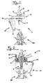
- Fig. 1
- eine schematische Seitenansicht einer Ausführungsform des erfindungsgemäßen Werkzeugschnellwechselsystems (mit HSK Aufnahme)
- Fig. 2
- eine Längsschnittdarstellung Werkzeugschnellwechselsystems gemäß der
Fig. 1 (mit Dorn) - Fig. 3
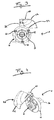
- eine Draufsicht auf das Werkzeugschnellwechselsystems gemäß der
Fig. 1 und Fig. 2 - Fig. 4
- eine isometrische Perspektivansicht eines erfindungsgemäßen Werkzeugschnellwechselsystems gemäß der
Fig. 1
- Fig. 1
- a schematic side view of an embodiment of the tool quick change system according to the invention (with HSK recording)
- Fig. 2
- a longitudinal sectional view tool quick change system according to the
Fig. 1 (with thorn) - Fig. 3
- a plan view of the quick tool change system according to the
Fig. 1 and Fig. 2 - Fig. 4
- an isometric perspective view of a quick change tool according to the invention according to the
Fig. 1
Das Werkzeugschnellwechselsystem 1 umfasst ferner eine Späneleiteinrichtung 20, die mit der Drehmomentstütze 10 drehfest verbunden ist. Diese Verbindung wird über eine Stützstruktur 26 sichergestellt. Die Späneleiteinrichtung dient zur Ableitung der beim Bearbeitungsprozess angefallenen Späne und umfasst daher einen Späneleitkörper 22. Dieser umschließt die Bearbeitungszone, mit dem Werkzeug 30, zu einem Teil. Der Späneleitkörper 22 kann dabei in mindestens zwei Bereiche geteilt werden. Der erste Bereich ist mittels der Stützstruktur 26 mit der Drehmomentstütze 10 verbunden. Dieser ist flach ausgebildet, um eine exakte Kontaktfläche zwischen Stützstruktur und Späneleitkörper sicherzustellen. Eine sehr genaue Positionierung ist dadurch möglich. Zusätzlich schafft der gerade Bereich Raum, um die Späne nach dem Durchlaufen eines zweiten, gewölbten Bereichs entsprechend weit vom Werkzeug 30 abzuleiten. Das Werkzeug 30 erfährt so keine Beeinträchtigung durch lose Teile. Der zweite Bereich des Späneleitkörpers 22 besitzt eine gewölbte Form um die Späne wieder in Richtung Werkzeugmaschinenraum zu leiten. Dies kann auch für eine vorhandene Absaugeinrichtung von belangen sein, da so die Späne besser gebündelt werden und eine effizientere Absaugung stattfindet. Um den Auswurf der Späne aus dem Späneleitkörper 22 zu verbessern wurde darüber hinaus ein Ausschnitt 24 im unteren Teil des Körpers geschaffen. Dieser Ausschnitt ist formlich so gestaltet, dass er einen Teil einer Bogenkurve darstellt.The tool quick change system 1 further comprises a
Die für die Bearbeitungsfunktion entscheidende Einheit innerhalb des Werkzeugschnellwechselsystems 1 ist eine Werkzeugschnittstelle 2. Die Schnittstelle stellt in ihrer Form eine Welle dar, erstreckt sich entlang der X-Achse und wird von der Drehmomentstütze 10 umschlossen. Am oberen Ende der Werkzeugschnittstelle 2 befindet sich eine Aufnahme für die Werkzeugmaschine 3. Diese kann nach Belieben des Kunden ausgeführt werden und ist werkzeugmaschinenabhängig. Die andere, untere Seite der Welle weist einen HSK Adapter 4 auf. Diese ist in
Die Schnittzeichnung aus
Die vorher offenbarten Eigenschaften der Drehmomentstütze 10 und der Späneleiteinrichtung 20 bleiben im Werkzeugschnellwechselsystem 1 aus
Ein Werkzeugschnellwechselsystem 1 gemäß einer der beiden vorherigen Ausführungsformen der vorliegenden Erfindung ist schematisch in
Einen vollständigen Überblick über das Werkzeugschnellwechselsystem 1 gibt die perspektivische
Um das Werkzeugschnellwechselsystem 1 betreiben zu können, kann die Drehmomentstütze 10 samt Späneleiteinrichtung 20 am Werkzeugkopf der Werkzeugmaschine montiert werden. Die Werkzeugschnittstelle 2 wird idealerweise vor dem Einbau mit einem Werkzeug 30 versehen. Der Vorteil ist, dass durch die vorherige Montage ein einfacher Auswuchtprozess stattfinden kann. Zudem kann das Werkzeug samt Werkzeugschnittstelle gereinigt werden, ohne dass dadurch die Lagereinrichtung beschädigt wird. Die Werkzeugschnittstelle 2 samt Werkzeug 30 wird anschließend von unten, entlang der X-Achse, in die Hohlwelle 13 der Drehmomentstütze 10 geschoben. Das obere Ende der Schnittstelle 3 wird an der Werkzeugmaschine positioniert bevor die Werkzeugschnittstelle handfest aufgeschoben wird. Durch das Anziehen oder Betätigen des Fixierelements 12 wird die Werkzeugschnittstelle gegen die Wellenschulter der Hohlwelle 13 gedrückt und bildet so einen Formschluss. Gleichzeitig verjüngt das Fixierelement 12, durch einen Keil im Fixierelement, die Hohlwelle 13 und presst diese auf die Werkzeugschnittstelle. Durch die sichere Verbindung der Bauteile ist sichergestellt, dass die Lagereinrichtung 14 bei hohen Drehzahlen der Werkzeugschnittstelle 2 einwandfrei und schadenfrei funktioniert. Es wurde festgestellt, dass diese Verbindung eine positive Auswirkung auf die Genauigkeit bei der Bearbeitung hat.In order to operate the tool quick change system 1, the
Die Bearbeitung von bevorzugt plattenförmigen Werkstücken, die bevorzugt zumindest abschnittsweise aus Holz, Holzwerkstoffen oder Kunststoff bestehen, erfolgt nun wie gewohnt. Folgt der Werkzeugkopf der Werkzeugmaschine nun einer Kontur, beim Bearbeiten eines plattenförmigen Werkstückes, wird der Späneleitkörper 22 in einer Weise automatisch nachgeführt, so dass der Späneleitkörper relativ zum Werkstück gesehen immer in derselben Position mitgeführt wird. Dadurch ist es möglich den Späneleitkörper, ohne Nachjustieren über den gesamten Arbeitsprozess, optimal an den Spanflug anzupassen und so die Späne in eine kontrollierte Richtung zu lenken.The processing of preferably plate-shaped workpieces, which are preferably at least partially made of wood, wood materials or plastic, now takes place as usual. If the tool head of the machine tool now follows a contour when machining a plate-shaped workpiece, the
Es besteht die Möglichkeit, die Verfahrensschritte zum Einsetzen der Werkzeugschnittstelle 2 automatisiert ablaufen zu lassen. Eine Anpassung der Konstruktion ist nur bedingt nötig. Zudem kann die Werkzeugschnittstelle 2 auch ohne die Drehmomentstütze 10 und das Späneleitelement 20 betrieben werden.It is possible to run the process steps for inserting the
Claims (13)
Priority Applications (1)
| Application Number | Priority Date | Filing Date | Title |
|---|---|---|---|
| PL16167743T PL3090831T3 (en) | 2015-05-06 | 2016-04-29 | Quick-change tool system with chip guide device |
Applications Claiming Priority (1)
| Application Number | Priority Date | Filing Date | Title |
|---|---|---|---|
| DE202015003373.3U DE202015003373U1 (en) | 2015-05-06 | 2015-05-06 | Quick tool changing system with chip guiding device |
Publications (2)
| Publication Number | Publication Date |
|---|---|
| EP3090831A1 true EP3090831A1 (en) | 2016-11-09 |
| EP3090831B1 EP3090831B1 (en) | 2022-01-26 |
Family
ID=54262109
Family Applications (1)
| Application Number | Title | Priority Date | Filing Date |
|---|---|---|---|
| EP16167743.0A Active EP3090831B1 (en) | 2015-05-06 | 2016-04-29 | Quick-change tool system with chip guide device |
Country Status (3)
| Country | Link |
|---|---|
| EP (1) | EP3090831B1 (en) |
| DE (1) | DE202015003373U1 (en) |
| PL (1) | PL3090831T3 (en) |
Cited By (1)
| Publication number | Priority date | Publication date | Assignee | Title |
|---|---|---|---|---|
| CN106976131A (en) * | 2017-05-23 | 2017-07-25 | 慈溪智江机械科技有限公司 | A kind of plate drilling device for the drill bit that can automatically switch |
Families Citing this family (2)
| Publication number | Priority date | Publication date | Assignee | Title |
|---|---|---|---|---|
| CN116237971A (en) * | 2017-04-07 | 2023-06-09 | 睿信科机器人股份有限公司 | Quick release mechanism for tool adapter plate and robot provided with same |
| IT201900018800A1 (en) * | 2019-10-15 | 2021-04-15 | Scm Group Spa | Chip shielding device for a processing assembly and processing machine comprising the device. |
Citations (11)
| Publication number | Priority date | Publication date | Assignee | Title |
|---|---|---|---|---|
| EP0407836A2 (en) * | 1989-07-04 | 1991-01-16 | Mitsubishi Materials Corporation | Rotary cutting tool |
| DE4480343T1 (en) * | 1993-12-30 | 1997-03-27 | Horkos Corp | Device for removing chips, designed for a machine tool |
| JPH10113839A (en) * | 1996-10-14 | 1998-05-06 | Sumitomo Electric Ind Ltd | Chip collecting device |
| DE29907571U1 (en) | 1999-04-28 | 1999-07-29 | Homag Maschinenbau Ag | Chip guide device for a cutting unit and cutting unit with such a chip guide device |
| EP0955125A2 (en) * | 1998-05-07 | 1999-11-10 | Mitsubishi Materials Corporation | Cutting tool |
| JP2002036056A (en) * | 2000-07-21 | 2002-02-05 | Honda Motor Co Ltd | Cutting device |
| DE10136996A1 (en) * | 2001-07-24 | 2003-02-20 | Mapal Fab Praezision | Tool |
| DE60013853T2 (en) * | 1999-02-22 | 2005-09-22 | Horkos Corp., Fukuyama | TOOL MACHINE WITH SPAN SUCTION UNIT |
| EP1985396A1 (en) * | 2007-04-25 | 2008-10-29 | Homag Holzbearbeitungssysteme AG | Interchangeable tool assembly |
| EP2251141A1 (en) | 2009-05-16 | 2010-11-17 | Ledermann GmbH & Co. KG | Machine assembly with an extractor hood |
| EP2420347A1 (en) * | 2010-08-20 | 2012-02-22 | Homag Holzbearbeitungssysteme AG | Processing device with tiltable processing head |
-
2015
- 2015-05-06 DE DE202015003373.3U patent/DE202015003373U1/en active Active
-
2016
- 2016-04-29 EP EP16167743.0A patent/EP3090831B1/en active Active
- 2016-04-29 PL PL16167743T patent/PL3090831T3/en unknown
Patent Citations (11)
| Publication number | Priority date | Publication date | Assignee | Title |
|---|---|---|---|---|
| EP0407836A2 (en) * | 1989-07-04 | 1991-01-16 | Mitsubishi Materials Corporation | Rotary cutting tool |
| DE4480343T1 (en) * | 1993-12-30 | 1997-03-27 | Horkos Corp | Device for removing chips, designed for a machine tool |
| JPH10113839A (en) * | 1996-10-14 | 1998-05-06 | Sumitomo Electric Ind Ltd | Chip collecting device |
| EP0955125A2 (en) * | 1998-05-07 | 1999-11-10 | Mitsubishi Materials Corporation | Cutting tool |
| DE60013853T2 (en) * | 1999-02-22 | 2005-09-22 | Horkos Corp., Fukuyama | TOOL MACHINE WITH SPAN SUCTION UNIT |
| DE29907571U1 (en) | 1999-04-28 | 1999-07-29 | Homag Maschinenbau Ag | Chip guide device for a cutting unit and cutting unit with such a chip guide device |
| JP2002036056A (en) * | 2000-07-21 | 2002-02-05 | Honda Motor Co Ltd | Cutting device |
| DE10136996A1 (en) * | 2001-07-24 | 2003-02-20 | Mapal Fab Praezision | Tool |
| EP1985396A1 (en) * | 2007-04-25 | 2008-10-29 | Homag Holzbearbeitungssysteme AG | Interchangeable tool assembly |
| EP2251141A1 (en) | 2009-05-16 | 2010-11-17 | Ledermann GmbH & Co. KG | Machine assembly with an extractor hood |
| EP2420347A1 (en) * | 2010-08-20 | 2012-02-22 | Homag Holzbearbeitungssysteme AG | Processing device with tiltable processing head |
Cited By (1)
| Publication number | Priority date | Publication date | Assignee | Title |
|---|---|---|---|---|
| CN106976131A (en) * | 2017-05-23 | 2017-07-25 | 慈溪智江机械科技有限公司 | A kind of plate drilling device for the drill bit that can automatically switch |
Also Published As
| Publication number | Publication date |
|---|---|
| PL3090831T3 (en) | 2022-04-04 |
| EP3090831B1 (en) | 2022-01-26 |
| DE202015003373U1 (en) | 2015-09-23 |
Similar Documents
| Publication | Publication Date | Title |
|---|---|---|
| EP2915642B1 (en) | Construction machine | |
| EP3043946B1 (en) | Coolant supply and skiving machine equipped therewith, and skiving method carried out therewith | |
| EP2551054B1 (en) | Assembly for grinding electrodes | |
| WO2014118264A1 (en) | Tool holder for a tool with a tool shaft provided with an outer thread | |
| EP0106081A2 (en) | Machine tool with tool magazine | |
| DE102013107858B4 (en) | Tool for turn-turn broaching of workpieces | |
| DE102018003132B4 (en) | machine tool | |
| EP3090831A1 (en) | Quick-change tool system with chip guide device | |
| EP0523574A2 (en) | Clamping device for single tools | |
| EP2251141B1 (en) | Machine assembly with an extractor hood | |
| EP2123379A1 (en) | Milling and turning machine | |
| DE102006048495A1 (en) | Processing system for finish cutting of connecting rod lug, has spindles provided with honing tools and delivering device which is connected with adjusting device, where cutting of tools is controlled by delivering and adjusting devices | |
| EP0328958B1 (en) | Device for working rotation-symmetrical work piece surfaces | |
| DE202017101113U1 (en) | Brushing device for grinding and / or polishing tools | |
| DE102008046086B4 (en) | grinding machine | |
| DE102018119980A1 (en) | Clamping or gripping device | |
| WO2018234193A1 (en) | Working spindle having a radial clamp device | |
| DE102019111843B4 (en) | cutting tool | |
| EP1600233A2 (en) | Holder for a tool drive unit, in particular for the automatic deburring, the removal of sharp edges or the smoothing of workpieces | |
| WO1998040189A1 (en) | Workpiece feed device for a machine tool | |
| DE202007014828U1 (en) | Chuck for exciting parts | |
| EP0123918B1 (en) | Cutter arbor and mandrel | |
| EP3043938B1 (en) | Cutting tool | |
| EP1479491A1 (en) | Planer | |
| DE2257653C3 (en) | Drill head |
Legal Events
| Date | Code | Title | Description |
|---|---|---|---|
| PUAI | Public reference made under article 153(3) epc to a published international application that has entered the european phase |
Free format text: ORIGINAL CODE: 0009012 |
|
| AK | Designated contracting states |
Kind code of ref document: A1 Designated state(s): AL AT BE BG CH CY CZ DE DK EE ES FI FR GB GR HR HU IE IS IT LI LT LU LV MC MK MT NL NO PL PT RO RS SE SI SK SM TR |
|
| AX | Request for extension of the european patent |
Extension state: BA ME |
|
| STAA | Information on the status of an ep patent application or granted ep patent |
Free format text: STATUS: REQUEST FOR EXAMINATION WAS MADE |
|
| 17P | Request for examination filed |
Effective date: 20170418 |
|
| RBV | Designated contracting states (corrected) |
Designated state(s): AL AT BE BG CH CY CZ DE DK EE ES FI FR GB GR HR HU IE IS IT LI LT LU LV MC MK MT NL NO PL PT RO RS SE SI SK SM TR |
|
| STAA | Information on the status of an ep patent application or granted ep patent |
Free format text: STATUS: EXAMINATION IS IN PROGRESS |
|
| 17Q | First examination report despatched |
Effective date: 20170823 |
|
| STAA | Information on the status of an ep patent application or granted ep patent |
Free format text: STATUS: EXAMINATION IS IN PROGRESS |
|
| GRAP | Despatch of communication of intention to grant a patent |
Free format text: ORIGINAL CODE: EPIDOSNIGR1 |
|
| STAA | Information on the status of an ep patent application or granted ep patent |
Free format text: STATUS: GRANT OF PATENT IS INTENDED |
|
| INTG | Intention to grant announced |
Effective date: 20210813 |
|
| GRAS | Grant fee paid |
Free format text: ORIGINAL CODE: EPIDOSNIGR3 |
|
| GRAA | (expected) grant |
Free format text: ORIGINAL CODE: 0009210 |
|
| STAA | Information on the status of an ep patent application or granted ep patent |
Free format text: STATUS: THE PATENT HAS BEEN GRANTED |
|
| AK | Designated contracting states |
Kind code of ref document: B1 Designated state(s): AL AT BE BG CH CY CZ DE DK EE ES FI FR GB GR HR HU IE IS IT LI LT LU LV MC MK MT NL NO PL PT RO RS SE SI SK SM TR |
|
| REG | Reference to a national code |
Ref country code: GB Ref legal event code: FG4D Free format text: NOT ENGLISH |
|
| REG | Reference to a national code |
Ref country code: CH Ref legal event code: EP |
|
| REG | Reference to a national code |
Ref country code: AT Ref legal event code: REF Ref document number: 1464884 Country of ref document: AT Kind code of ref document: T Effective date: 20220215 |
|
| REG | Reference to a national code |
Ref country code: IE Ref legal event code: FG4D Free format text: LANGUAGE OF EP DOCUMENT: GERMAN |
|
| REG | Reference to a national code |
Ref country code: DE Ref legal event code: R096 Ref document number: 502016014445 Country of ref document: DE |
|
| REG | Reference to a national code |
Ref country code: LT Ref legal event code: MG9D |
|
| REG | Reference to a national code |
Ref country code: NL Ref legal event code: MP Effective date: 20220126 |
|
| PG25 | Lapsed in a contracting state [announced via postgrant information from national office to epo] |
Ref country code: NL Free format text: LAPSE BECAUSE OF FAILURE TO SUBMIT A TRANSLATION OF THE DESCRIPTION OR TO PAY THE FEE WITHIN THE PRESCRIBED TIME-LIMIT Effective date: 20220126 |
|
| PG25 | Lapsed in a contracting state [announced via postgrant information from national office to epo] |
Ref country code: SE Free format text: LAPSE BECAUSE OF FAILURE TO SUBMIT A TRANSLATION OF THE DESCRIPTION OR TO PAY THE FEE WITHIN THE PRESCRIBED TIME-LIMIT Effective date: 20220126 Ref country code: RS Free format text: LAPSE BECAUSE OF FAILURE TO SUBMIT A TRANSLATION OF THE DESCRIPTION OR TO PAY THE FEE WITHIN THE PRESCRIBED TIME-LIMIT Effective date: 20220126 Ref country code: PT Free format text: LAPSE BECAUSE OF FAILURE TO SUBMIT A TRANSLATION OF THE DESCRIPTION OR TO PAY THE FEE WITHIN THE PRESCRIBED TIME-LIMIT Effective date: 20220526 Ref country code: NO Free format text: LAPSE BECAUSE OF FAILURE TO SUBMIT A TRANSLATION OF THE DESCRIPTION OR TO PAY THE FEE WITHIN THE PRESCRIBED TIME-LIMIT Effective date: 20220426 Ref country code: LT Free format text: LAPSE BECAUSE OF FAILURE TO SUBMIT A TRANSLATION OF THE DESCRIPTION OR TO PAY THE FEE WITHIN THE PRESCRIBED TIME-LIMIT Effective date: 20220126 Ref country code: HR Free format text: LAPSE BECAUSE OF FAILURE TO SUBMIT A TRANSLATION OF THE DESCRIPTION OR TO PAY THE FEE WITHIN THE PRESCRIBED TIME-LIMIT Effective date: 20220126 Ref country code: ES Free format text: LAPSE BECAUSE OF FAILURE TO SUBMIT A TRANSLATION OF THE DESCRIPTION OR TO PAY THE FEE WITHIN THE PRESCRIBED TIME-LIMIT Effective date: 20220126 Ref country code: BG Free format text: LAPSE BECAUSE OF FAILURE TO SUBMIT A TRANSLATION OF THE DESCRIPTION OR TO PAY THE FEE WITHIN THE PRESCRIBED TIME-LIMIT Effective date: 20220426 |
|
| PG25 | Lapsed in a contracting state [announced via postgrant information from national office to epo] |
Ref country code: LV Free format text: LAPSE BECAUSE OF FAILURE TO SUBMIT A TRANSLATION OF THE DESCRIPTION OR TO PAY THE FEE WITHIN THE PRESCRIBED TIME-LIMIT Effective date: 20220126 Ref country code: GR Free format text: LAPSE BECAUSE OF FAILURE TO SUBMIT A TRANSLATION OF THE DESCRIPTION OR TO PAY THE FEE WITHIN THE PRESCRIBED TIME-LIMIT Effective date: 20220427 Ref country code: FI Free format text: LAPSE BECAUSE OF FAILURE TO SUBMIT A TRANSLATION OF THE DESCRIPTION OR TO PAY THE FEE WITHIN THE PRESCRIBED TIME-LIMIT Effective date: 20220126 |
|
| PG25 | Lapsed in a contracting state [announced via postgrant information from national office to epo] |
Ref country code: IS Free format text: LAPSE BECAUSE OF FAILURE TO SUBMIT A TRANSLATION OF THE DESCRIPTION OR TO PAY THE FEE WITHIN THE PRESCRIBED TIME-LIMIT Effective date: 20220526 |
|
| REG | Reference to a national code |
Ref country code: DE Ref legal event code: R097 Ref document number: 502016014445 Country of ref document: DE |
|
| PG25 | Lapsed in a contracting state [announced via postgrant information from national office to epo] |
Ref country code: SM Free format text: LAPSE BECAUSE OF FAILURE TO SUBMIT A TRANSLATION OF THE DESCRIPTION OR TO PAY THE FEE WITHIN THE PRESCRIBED TIME-LIMIT Effective date: 20220126 Ref country code: SK Free format text: LAPSE BECAUSE OF FAILURE TO SUBMIT A TRANSLATION OF THE DESCRIPTION OR TO PAY THE FEE WITHIN THE PRESCRIBED TIME-LIMIT Effective date: 20220126 Ref country code: RO Free format text: LAPSE BECAUSE OF FAILURE TO SUBMIT A TRANSLATION OF THE DESCRIPTION OR TO PAY THE FEE WITHIN THE PRESCRIBED TIME-LIMIT Effective date: 20220126 Ref country code: EE Free format text: LAPSE BECAUSE OF FAILURE TO SUBMIT A TRANSLATION OF THE DESCRIPTION OR TO PAY THE FEE WITHIN THE PRESCRIBED TIME-LIMIT Effective date: 20220126 Ref country code: DK Free format text: LAPSE BECAUSE OF FAILURE TO SUBMIT A TRANSLATION OF THE DESCRIPTION OR TO PAY THE FEE WITHIN THE PRESCRIBED TIME-LIMIT Effective date: 20220126 Ref country code: CZ Free format text: LAPSE BECAUSE OF FAILURE TO SUBMIT A TRANSLATION OF THE DESCRIPTION OR TO PAY THE FEE WITHIN THE PRESCRIBED TIME-LIMIT Effective date: 20220126 |
|
| PG25 | Lapsed in a contracting state [announced via postgrant information from national office to epo] |
Ref country code: AL Free format text: LAPSE BECAUSE OF FAILURE TO SUBMIT A TRANSLATION OF THE DESCRIPTION OR TO PAY THE FEE WITHIN THE PRESCRIBED TIME-LIMIT Effective date: 20220126 |
|
| REG | Reference to a national code |
Ref country code: CH Ref legal event code: PL |
|
| PLBE | No opposition filed within time limit |
Free format text: ORIGINAL CODE: 0009261 |
|
| STAA | Information on the status of an ep patent application or granted ep patent |
Free format text: STATUS: NO OPPOSITION FILED WITHIN TIME LIMIT |
|
| GBPC | Gb: european patent ceased through non-payment of renewal fee |
Effective date: 20220429 |
|
| 26N | No opposition filed |
Effective date: 20221027 |
|
| REG | Reference to a national code |
Ref country code: BE Ref legal event code: MM Effective date: 20220430 |
|
| PG25 | Lapsed in a contracting state [announced via postgrant information from national office to epo] |
Ref country code: MC Free format text: LAPSE BECAUSE OF FAILURE TO SUBMIT A TRANSLATION OF THE DESCRIPTION OR TO PAY THE FEE WITHIN THE PRESCRIBED TIME-LIMIT Effective date: 20220126 Ref country code: LU Free format text: LAPSE BECAUSE OF NON-PAYMENT OF DUE FEES Effective date: 20220429 Ref country code: LI Free format text: LAPSE BECAUSE OF NON-PAYMENT OF DUE FEES Effective date: 20220430 Ref country code: GB Free format text: LAPSE BECAUSE OF NON-PAYMENT OF DUE FEES Effective date: 20220429 Ref country code: FR Free format text: LAPSE BECAUSE OF NON-PAYMENT OF DUE FEES Effective date: 20220430 Ref country code: CH Free format text: LAPSE BECAUSE OF NON-PAYMENT OF DUE FEES Effective date: 20220430 |
|
| PG25 | Lapsed in a contracting state [announced via postgrant information from national office to epo] |
Ref country code: SI Free format text: LAPSE BECAUSE OF FAILURE TO SUBMIT A TRANSLATION OF THE DESCRIPTION OR TO PAY THE FEE WITHIN THE PRESCRIBED TIME-LIMIT Effective date: 20220126 Ref country code: BE Free format text: LAPSE BECAUSE OF NON-PAYMENT OF DUE FEES Effective date: 20220430 |
|
| PG25 | Lapsed in a contracting state [announced via postgrant information from national office to epo] |
Ref country code: IE Free format text: LAPSE BECAUSE OF NON-PAYMENT OF DUE FEES Effective date: 20220429 |
|
| PGFP | Annual fee paid to national office [announced via postgrant information from national office to epo] |
Ref country code: PL Payment date: 20230330 Year of fee payment: 8 |
|
| REG | Reference to a national code |
Ref country code: AT Ref legal event code: MM01 Ref document number: 1464884 Country of ref document: AT Kind code of ref document: T Effective date: 20220429 |
|
| P01 | Opt-out of the competence of the unified patent court (upc) registered |
Effective date: 20230529 |
|
| PG25 | Lapsed in a contracting state [announced via postgrant information from national office to epo] |
Ref country code: AT Free format text: LAPSE BECAUSE OF NON-PAYMENT OF DUE FEES Effective date: 20220429 |
|
| PGFP | Annual fee paid to national office [announced via postgrant information from national office to epo] |
Ref country code: IT Payment date: 20230414 Year of fee payment: 8 Ref country code: DE Payment date: 20220615 Year of fee payment: 8 |
|
| PG25 | Lapsed in a contracting state [announced via postgrant information from national office to epo] |
Ref country code: HU Free format text: LAPSE BECAUSE OF FAILURE TO SUBMIT A TRANSLATION OF THE DESCRIPTION OR TO PAY THE FEE WITHIN THE PRESCRIBED TIME-LIMIT; INVALID AB INITIO Effective date: 20160429 |