EP3090815A1 - Directly printed panel with two layer structure - Google Patents
Directly printed panel with two layer structure Download PDFInfo
- Publication number
- EP3090815A1 EP3090815A1 EP16170657.7A EP16170657A EP3090815A1 EP 3090815 A1 EP3090815 A1 EP 3090815A1 EP 16170657 A EP16170657 A EP 16170657A EP 3090815 A1 EP3090815 A1 EP 3090815A1
- Authority
- EP
- European Patent Office
- Prior art keywords
- layer
- radiation
- panel according
- panel
- thickness
- Prior art date
- Legal status (The legal status is an assumption and is not a legal conclusion. Google has not performed a legal analysis and makes no representation as to the accuracy of the status listed.)
- Granted
Links
- 229920000642 polymer Polymers 0.000 claims abstract description 18
- 238000007639 printing Methods 0.000 claims description 54
- NIXOWILDQLNWCW-UHFFFAOYSA-M Acrylate Chemical compound [O-]C(=O)C=C NIXOWILDQLNWCW-UHFFFAOYSA-M 0.000 claims description 48
- 238000000034 method Methods 0.000 claims description 26
- 239000000463 material Substances 0.000 claims description 23
- 239000007788 liquid Substances 0.000 claims description 22
- 230000005855 radiation Effects 0.000 claims description 22
- 241000428199 Mustelinae Species 0.000 claims description 20
- 125000001931 aliphatic group Chemical group 0.000 claims description 15
- 241000282342 Martes americana Species 0.000 claims description 9
- JWYVGKFDLWWQJX-UHFFFAOYSA-N 1-ethenylazepan-2-one Chemical compound C=CN1CCCCCC1=O JWYVGKFDLWWQJX-UHFFFAOYSA-N 0.000 claims description 6
- 230000008878 coupling Effects 0.000 claims description 6
- 238000010168 coupling process Methods 0.000 claims description 6
- 238000005859 coupling reaction Methods 0.000 claims description 6
- 239000002985 plastic film Substances 0.000 claims description 6
- 229920006255 plastic film Polymers 0.000 claims description 6
- 230000008569 process Effects 0.000 claims description 6
- 238000013016 damping Methods 0.000 claims description 4
- 230000000694 effects Effects 0.000 claims description 4
- 239000007858 starting material Substances 0.000 claims description 2
- 238000004519 manufacturing process Methods 0.000 abstract description 14
- 239000010410 layer Substances 0.000 description 203
- 239000000976 ink Substances 0.000 description 40
- 235000019589 hardness Nutrition 0.000 description 37
- 239000000203 mixture Substances 0.000 description 18
- 239000011248 coating agent Substances 0.000 description 17
- 238000000576 coating method Methods 0.000 description 17
- 239000004800 polyvinyl chloride Substances 0.000 description 17
- 229920000915 polyvinyl chloride Polymers 0.000 description 16
- 238000001723 curing Methods 0.000 description 14
- 239000000123 paper Substances 0.000 description 11
- 239000006185 dispersion Substances 0.000 description 10
- 239000003973 paint Substances 0.000 description 10
- 239000002023 wood Substances 0.000 description 10
- 238000005299 abrasion Methods 0.000 description 8
- 239000000654 additive Substances 0.000 description 8
- 239000000839 emulsion Substances 0.000 description 8
- 238000001035 drying Methods 0.000 description 6
- 229920000877 Melamine resin Polymers 0.000 description 5
- 230000008901 benefit Effects 0.000 description 5
- 238000009408 flooring Methods 0.000 description 5
- 238000009434 installation Methods 0.000 description 5
- 239000000049 pigment Substances 0.000 description 5
- 238000003847 radiation curing Methods 0.000 description 5
- 229920005989 resin Polymers 0.000 description 5
- 239000011347 resin Substances 0.000 description 5
- NIXOWILDQLNWCW-UHFFFAOYSA-N 2-Propenoic acid Natural products OC(=O)C=C NIXOWILDQLNWCW-UHFFFAOYSA-N 0.000 description 4
- FIHBHSQYSYVZQE-UHFFFAOYSA-N 6-prop-2-enoyloxyhexyl prop-2-enoate Chemical compound C=CC(=O)OCCCCCCOC(=O)C=C FIHBHSQYSYVZQE-UHFFFAOYSA-N 0.000 description 4
- 241000196324 Embryophyta Species 0.000 description 4
- 150000001252 acrylic acid derivatives Chemical class 0.000 description 4
- TZCXTZWJZNENPQ-UHFFFAOYSA-L barium sulfate Chemical compound [Ba+2].[O-]S([O-])(=O)=O TZCXTZWJZNENPQ-UHFFFAOYSA-L 0.000 description 4
- 239000011230 binding agent Substances 0.000 description 4
- 239000002245 particle Substances 0.000 description 4
- 229920000728 polyester Polymers 0.000 description 4
- 238000006116 polymerization reaction Methods 0.000 description 4
- 229920002635 polyurethane Polymers 0.000 description 4
- 239000004814 polyurethane Substances 0.000 description 4
- 230000009467 reduction Effects 0.000 description 4
- 239000002904 solvent Substances 0.000 description 4
- XLYOFNOQVPJJNP-UHFFFAOYSA-N water Substances O XLYOFNOQVPJJNP-UHFFFAOYSA-N 0.000 description 4
- 239000004640 Melamine resin Substances 0.000 description 3
- 125000005396 acrylic acid ester group Chemical group 0.000 description 3
- 238000007646 gravure printing Methods 0.000 description 3
- 230000006872 improvement Effects 0.000 description 3
- 239000006224 matting agent Substances 0.000 description 3
- 238000005259 measurement Methods 0.000 description 3
- ZDHCZVWCTKTBRY-UHFFFAOYSA-N omega-Hydroxydodecanoic acid Natural products OCCCCCCCCCCCC(O)=O ZDHCZVWCTKTBRY-UHFFFAOYSA-N 0.000 description 3
- FAQJJMHZNSSFSM-UHFFFAOYSA-N phenylglyoxylic acid Chemical compound OC(=O)C(=O)C1=CC=CC=C1 FAQJJMHZNSSFSM-UHFFFAOYSA-N 0.000 description 3
- 230000000704 physical effect Effects 0.000 description 3
- 229920003023 plastic Polymers 0.000 description 3
- 239000004033 plastic Substances 0.000 description 3
- 239000002994 raw material Substances 0.000 description 3
- 238000001228 spectrum Methods 0.000 description 3
- 239000000758 substrate Substances 0.000 description 3
- 238000012360 testing method Methods 0.000 description 3
- KWVGIHKZDCUPEU-UHFFFAOYSA-N 2,2-dimethoxy-2-phenylacetophenone Chemical compound C=1C=CC=CC=1C(OC)(OC)C(=O)C1=CC=CC=C1 KWVGIHKZDCUPEU-UHFFFAOYSA-N 0.000 description 2
- 239000004721 Polyphenylene oxide Substances 0.000 description 2
- 229920002396 Polyurea Polymers 0.000 description 2
- VYPSYNLAJGMNEJ-UHFFFAOYSA-N Silicium dioxide Chemical class O=[Si]=O VYPSYNLAJGMNEJ-UHFFFAOYSA-N 0.000 description 2
- GWEVSGVZZGPLCZ-UHFFFAOYSA-N Titan oxide Chemical compound O=[Ti]=O GWEVSGVZZGPLCZ-UHFFFAOYSA-N 0.000 description 2
- 230000004888 barrier function Effects 0.000 description 2
- 239000004568 cement Substances 0.000 description 2
- 230000008859 change Effects 0.000 description 2
- 238000010382 chemical cross-linking Methods 0.000 description 2
- 239000003086 colorant Substances 0.000 description 2
- 239000002131 composite material Substances 0.000 description 2
- 229910052593 corundum Inorganic materials 0.000 description 2
- 239000010431 corundum Substances 0.000 description 2
- -1 defoamers Substances 0.000 description 2
- 238000011161 development Methods 0.000 description 2
- UHESRSKEBRADOO-UHFFFAOYSA-N ethyl carbamate;prop-2-enoic acid Chemical compound OC(=O)C=C.CCOC(N)=O UHESRSKEBRADOO-UHFFFAOYSA-N 0.000 description 2
- 238000001704 evaporation Methods 0.000 description 2
- 230000008020 evaporation Effects 0.000 description 2
- 239000011094 fiberboard Substances 0.000 description 2
- 239000000945 filler Substances 0.000 description 2
- 238000009472 formulation Methods 0.000 description 2
- 238000009499 grossing Methods 0.000 description 2
- 239000011256 inorganic filler Substances 0.000 description 2
- 239000004922 lacquer Substances 0.000 description 2
- 239000000178 monomer Substances 0.000 description 2
- 230000003287 optical effect Effects 0.000 description 2
- 239000012766 organic filler Substances 0.000 description 2
- 229920000058 polyacrylate Polymers 0.000 description 2
- 229920000570 polyether Polymers 0.000 description 2
- 229920001296 polysiloxane Polymers 0.000 description 2
- 239000000843 powder Substances 0.000 description 2
- 238000003825 pressing Methods 0.000 description 2
- 238000012545 processing Methods 0.000 description 2
- 239000011241 protective layer Substances 0.000 description 2
- 238000004064 recycling Methods 0.000 description 2
- 230000035807 sensation Effects 0.000 description 2
- 235000019615 sensations Nutrition 0.000 description 2
- 239000007787 solid Substances 0.000 description 2
- 239000000454 talc Substances 0.000 description 2
- 229910052623 talc Inorganic materials 0.000 description 2
- 229920001169 thermoplastic Polymers 0.000 description 2
- 239000004416 thermosoftening plastic Substances 0.000 description 2
- 239000000080 wetting agent Substances 0.000 description 2
- ODIGIKRIUKFKHP-UHFFFAOYSA-N (n-propan-2-yloxycarbonylanilino) acetate Chemical compound CC(C)OC(=O)N(OC(C)=O)C1=CC=CC=C1 ODIGIKRIUKFKHP-UHFFFAOYSA-N 0.000 description 1
- SMZOUWXMTYCWNB-UHFFFAOYSA-N 2-(2-methoxy-5-methylphenyl)ethanamine Chemical compound COC1=CC=C(C)C=C1CCN SMZOUWXMTYCWNB-UHFFFAOYSA-N 0.000 description 1
- 239000004925 Acrylic resin Substances 0.000 description 1
- 229920000178 Acrylic resin Polymers 0.000 description 1
- 238000012935 Averaging Methods 0.000 description 1
- ZAMOUSCENKQFHK-UHFFFAOYSA-N Chlorine atom Chemical compound [Cl] ZAMOUSCENKQFHK-UHFFFAOYSA-N 0.000 description 1
- 240000007049 Juglans regia Species 0.000 description 1
- 235000009496 Juglans regia Nutrition 0.000 description 1
- DAKWPKUUDNSNPN-UHFFFAOYSA-N Trimethylolpropane triacrylate Chemical compound C=CC(=O)OCC(CC)(COC(=O)C=C)COC(=O)C=C DAKWPKUUDNSNPN-UHFFFAOYSA-N 0.000 description 1
- YWIULWOWYIZJBX-UHFFFAOYSA-N [Cl].O1C=COC=C1 Chemical compound [Cl].O1C=COC=C1 YWIULWOWYIZJBX-UHFFFAOYSA-N 0.000 description 1
- 230000009471 action Effects 0.000 description 1
- 230000001070 adhesive effect Effects 0.000 description 1
- 150000008366 benzophenones Chemical class 0.000 description 1
- 230000015572 biosynthetic process Effects 0.000 description 1
- 238000005266 casting Methods 0.000 description 1
- 238000006243 chemical reaction Methods 0.000 description 1
- 239000000460 chlorine Substances 0.000 description 1
- 229910052801 chlorine Inorganic materials 0.000 description 1
- 230000000295 complement effect Effects 0.000 description 1
- 150000001875 compounds Chemical class 0.000 description 1
- 239000000470 constituent Substances 0.000 description 1
- 238000010276 construction Methods 0.000 description 1
- 238000012937 correction Methods 0.000 description 1
- 239000007822 coupling agent Substances 0.000 description 1
- 238000004132 cross linking Methods 0.000 description 1
- 238000007766 curtain coating Methods 0.000 description 1
- 238000005034 decoration Methods 0.000 description 1
- 238000010017 direct printing Methods 0.000 description 1
- 239000000986 disperse dye Substances 0.000 description 1
- 229920001971 elastomer Polymers 0.000 description 1
- 238000005516 engineering process Methods 0.000 description 1
- 150000002576 ketones Chemical class 0.000 description 1
- JDSHMPZPIAZGSV-UHFFFAOYSA-N melamine Chemical compound NC1=NC(N)=NC(N)=N1 JDSHMPZPIAZGSV-UHFFFAOYSA-N 0.000 description 1
- 150000007974 melamines Chemical class 0.000 description 1
- QSHDDOUJBYECFT-UHFFFAOYSA-N mercury Chemical compound [Hg] QSHDDOUJBYECFT-UHFFFAOYSA-N 0.000 description 1
- 229910052753 mercury Inorganic materials 0.000 description 1
- 238000002156 mixing Methods 0.000 description 1
- 238000012986 modification Methods 0.000 description 1
- 230000004048 modification Effects 0.000 description 1
- 238000012806 monitoring device Methods 0.000 description 1
- 239000002105 nanoparticle Substances 0.000 description 1
- TWNQGVIAIRXVLR-UHFFFAOYSA-N oxo(oxoalumanyloxy)alumane Chemical compound O=[Al]O[Al]=O TWNQGVIAIRXVLR-UHFFFAOYSA-N 0.000 description 1
- PZXHOJFANUNWGC-UHFFFAOYSA-N phenyl 2-oxoacetate Chemical class O=CC(=O)OC1=CC=CC=C1 PZXHOJFANUNWGC-UHFFFAOYSA-N 0.000 description 1
- 239000004014 plasticizer Substances 0.000 description 1
- 230000008092 positive effect Effects 0.000 description 1
- XOFYZVNMUHMLCC-ZPOLXVRWSA-N prednisone Chemical compound O=C1C=C[C@]2(C)[C@H]3C(=O)C[C@](C)([C@@](CC4)(O)C(=O)CO)[C@@H]4[C@@H]3CCC2=C1 XOFYZVNMUHMLCC-ZPOLXVRWSA-N 0.000 description 1
- 238000010526 radical polymerization reaction Methods 0.000 description 1
- 238000005096 rolling process Methods 0.000 description 1
- 239000005060 rubber Substances 0.000 description 1
- RMAQACBXLXPBSY-UHFFFAOYSA-N silicic acid Chemical compound O[Si](O)(O)O RMAQACBXLXPBSY-UHFFFAOYSA-N 0.000 description 1
- 239000000377 silicon dioxide Substances 0.000 description 1
- 235000012239 silicon dioxide Nutrition 0.000 description 1
- 239000007779 soft material Substances 0.000 description 1
- 239000000126 substance Substances 0.000 description 1
- 239000004408 titanium dioxide Substances 0.000 description 1
- 238000012546 transfer Methods 0.000 description 1
- 238000011144 upstream manufacturing Methods 0.000 description 1
- 125000000391 vinyl group Chemical group [H]C([*])=C([H])[H] 0.000 description 1
- 229920002554 vinyl polymer Polymers 0.000 description 1
- 230000000007 visual effect Effects 0.000 description 1
- 235000020234 walnut Nutrition 0.000 description 1
Images

Classifications
-
- E—FIXED CONSTRUCTIONS
- E04—BUILDING
- E04C—STRUCTURAL ELEMENTS; BUILDING MATERIALS
- E04C2/00—Building elements of relatively thin form for the construction of parts of buildings, e.g. sheet materials, slabs, or panels
- E04C2/30—Building elements of relatively thin form for the construction of parts of buildings, e.g. sheet materials, slabs, or panels characterised by the shape or structure
-
- B—PERFORMING OPERATIONS; TRANSPORTING
- B05—SPRAYING OR ATOMISING IN GENERAL; APPLYING FLUENT MATERIALS TO SURFACES, IN GENERAL
- B05D—PROCESSES FOR APPLYING FLUENT MATERIALS TO SURFACES, IN GENERAL
- B05D7/00—Processes, other than flocking, specially adapted for applying liquids or other fluent materials to particular surfaces or for applying particular liquids or other fluent materials
- B05D7/50—Multilayers
- B05D7/56—Three layers or more
- B05D7/58—No clear coat specified
- B05D7/586—No clear coat specified each layer being cured, at least partially, separately
-
- B—PERFORMING OPERATIONS; TRANSPORTING
- B05—SPRAYING OR ATOMISING IN GENERAL; APPLYING FLUENT MATERIALS TO SURFACES, IN GENERAL
- B05D—PROCESSES FOR APPLYING FLUENT MATERIALS TO SURFACES, IN GENERAL
- B05D3/00—Pretreatment of surfaces to which liquids or other fluent materials are to be applied; After-treatment of applied coatings, e.g. intermediate treating of an applied coating preparatory to subsequent applications of liquids or other fluent materials
- B05D3/06—Pretreatment of surfaces to which liquids or other fluent materials are to be applied; After-treatment of applied coatings, e.g. intermediate treating of an applied coating preparatory to subsequent applications of liquids or other fluent materials by exposure to radiation
- B05D3/061—Pretreatment of surfaces to which liquids or other fluent materials are to be applied; After-treatment of applied coatings, e.g. intermediate treating of an applied coating preparatory to subsequent applications of liquids or other fluent materials by exposure to radiation using U.V.
- B05D3/065—After-treatment
- B05D3/067—Curing or cross-linking the coating
-
- B—PERFORMING OPERATIONS; TRANSPORTING
- B32—LAYERED PRODUCTS
- B32B—LAYERED PRODUCTS, i.e. PRODUCTS BUILT-UP OF STRATA OF FLAT OR NON-FLAT, e.g. CELLULAR OR HONEYCOMB, FORM
- B32B21/00—Layered products comprising a layer of wood, e.g. wood board, veneer, wood particle board
- B32B21/02—Layered products comprising a layer of wood, e.g. wood board, veneer, wood particle board the layer being formed of fibres, chips, or particles, e.g. MDF, HDF, OSB, chipboard, particle board, hardboard
-
- B—PERFORMING OPERATIONS; TRANSPORTING
- B32—LAYERED PRODUCTS
- B32B—LAYERED PRODUCTS, i.e. PRODUCTS BUILT-UP OF STRATA OF FLAT OR NON-FLAT, e.g. CELLULAR OR HONEYCOMB, FORM
- B32B21/00—Layered products comprising a layer of wood, e.g. wood board, veneer, wood particle board
- B32B21/04—Layered products comprising a layer of wood, e.g. wood board, veneer, wood particle board comprising wood as the main or only constituent of a layer, which is next to another layer of the same or of a different material
- B32B21/08—Layered products comprising a layer of wood, e.g. wood board, veneer, wood particle board comprising wood as the main or only constituent of a layer, which is next to another layer of the same or of a different material of synthetic resin
-
- B—PERFORMING OPERATIONS; TRANSPORTING
- B32—LAYERED PRODUCTS
- B32B—LAYERED PRODUCTS, i.e. PRODUCTS BUILT-UP OF STRATA OF FLAT OR NON-FLAT, e.g. CELLULAR OR HONEYCOMB, FORM
- B32B27/00—Layered products comprising a layer of synthetic resin
- B32B27/30—Layered products comprising a layer of synthetic resin comprising vinyl (co)polymers; comprising acrylic (co)polymers
- B32B27/308—Layered products comprising a layer of synthetic resin comprising vinyl (co)polymers; comprising acrylic (co)polymers comprising acrylic (co)polymers
-
- B—PERFORMING OPERATIONS; TRANSPORTING
- B44—DECORATIVE ARTS
- B44C—PRODUCING DECORATIVE EFFECTS; MOSAICS; TARSIA WORK; PAPERHANGING
- B44C1/00—Processes, not specifically provided for elsewhere, for producing decorative surface effects
-
- E—FIXED CONSTRUCTIONS
- E04—BUILDING
- E04C—STRUCTURAL ELEMENTS; BUILDING MATERIALS
- E04C2/00—Building elements of relatively thin form for the construction of parts of buildings, e.g. sheet materials, slabs, or panels
- E04C2/02—Building elements of relatively thin form for the construction of parts of buildings, e.g. sheet materials, slabs, or panels characterised by specified materials
- E04C2/10—Building elements of relatively thin form for the construction of parts of buildings, e.g. sheet materials, slabs, or panels characterised by specified materials of wood, fibres, chips, vegetable stems, or the like; of plastics; of foamed products
- E04C2/20—Building elements of relatively thin form for the construction of parts of buildings, e.g. sheet materials, slabs, or panels characterised by specified materials of wood, fibres, chips, vegetable stems, or the like; of plastics; of foamed products of plastics
-
- E—FIXED CONSTRUCTIONS
- E04—BUILDING
- E04C—STRUCTURAL ELEMENTS; BUILDING MATERIALS
- E04C2/00—Building elements of relatively thin form for the construction of parts of buildings, e.g. sheet materials, slabs, or panels
- E04C2/44—Building elements of relatively thin form for the construction of parts of buildings, e.g. sheet materials, slabs, or panels characterised by the purpose
- E04C2/46—Building elements of relatively thin form for the construction of parts of buildings, e.g. sheet materials, slabs, or panels characterised by the purpose specially adapted for making walls
-
- E—FIXED CONSTRUCTIONS
- E04—BUILDING
- E04C—STRUCTURAL ELEMENTS; BUILDING MATERIALS
- E04C2/00—Building elements of relatively thin form for the construction of parts of buildings, e.g. sheet materials, slabs, or panels
- E04C2/44—Building elements of relatively thin form for the construction of parts of buildings, e.g. sheet materials, slabs, or panels characterised by the purpose
- E04C2/50—Self-supporting slabs specially adapted for making floors ceilings, or roofs, e.g. able to be loaded
-
- E—FIXED CONSTRUCTIONS
- E04—BUILDING
- E04F—FINISHING WORK ON BUILDINGS, e.g. STAIRS, FLOORS
- E04F13/00—Coverings or linings, e.g. for walls or ceilings
- E04F13/07—Coverings or linings, e.g. for walls or ceilings composed of covering or lining elements; Sub-structures therefor; Fastening means therefor
- E04F13/08—Coverings or linings, e.g. for walls or ceilings composed of covering or lining elements; Sub-structures therefor; Fastening means therefor composed of a plurality of similar covering or lining elements
- E04F13/0889—Coverings or linings, e.g. for walls or ceilings composed of covering or lining elements; Sub-structures therefor; Fastening means therefor composed of a plurality of similar covering or lining elements characterised by the joints between neighbouring elements, e.g. with joint fillings or with tongue and groove connections
-
- E—FIXED CONSTRUCTIONS
- E04—BUILDING
- E04F—FINISHING WORK ON BUILDINGS, e.g. STAIRS, FLOORS
- E04F13/00—Coverings or linings, e.g. for walls or ceilings
- E04F13/07—Coverings or linings, e.g. for walls or ceilings composed of covering or lining elements; Sub-structures therefor; Fastening means therefor
- E04F13/08—Coverings or linings, e.g. for walls or ceilings composed of covering or lining elements; Sub-structures therefor; Fastening means therefor composed of a plurality of similar covering or lining elements
- E04F13/16—Coverings or linings, e.g. for walls or ceilings composed of covering or lining elements; Sub-structures therefor; Fastening means therefor composed of a plurality of similar covering or lining elements of fibres or chips, e.g. bonded with synthetic resins, or with an outer layer of fibres or chips
-
- E—FIXED CONSTRUCTIONS
- E04—BUILDING
- E04F—FINISHING WORK ON BUILDINGS, e.g. STAIRS, FLOORS
- E04F15/00—Flooring
- E04F15/02—Flooring or floor layers composed of a number of similar elements
- E04F15/02038—Flooring or floor layers composed of a number of similar elements characterised by tongue and groove connections between neighbouring flooring elements
-
- E—FIXED CONSTRUCTIONS
- E04—BUILDING
- E04F—FINISHING WORK ON BUILDINGS, e.g. STAIRS, FLOORS
- E04F15/00—Flooring
- E04F15/02—Flooring or floor layers composed of a number of similar elements
- E04F15/10—Flooring or floor layers composed of a number of similar elements of other materials, e.g. fibrous or chipped materials, organic plastics, magnesite tiles, hardboard, or with a top layer of other materials
- E04F15/102—Flooring or floor layers composed of a number of similar elements of other materials, e.g. fibrous or chipped materials, organic plastics, magnesite tiles, hardboard, or with a top layer of other materials of fibrous or chipped materials, e.g. bonded with synthetic resins
-
- E—FIXED CONSTRUCTIONS
- E04—BUILDING
- E04F—FINISHING WORK ON BUILDINGS, e.g. STAIRS, FLOORS
- E04F15/00—Flooring
- E04F15/02—Flooring or floor layers composed of a number of similar elements
- E04F15/10—Flooring or floor layers composed of a number of similar elements of other materials, e.g. fibrous or chipped materials, organic plastics, magnesite tiles, hardboard, or with a top layer of other materials
- E04F15/107—Flooring or floor layers composed of a number of similar elements of other materials, e.g. fibrous or chipped materials, organic plastics, magnesite tiles, hardboard, or with a top layer of other materials composed of several layers, e.g. sandwich panels
-
- B—PERFORMING OPERATIONS; TRANSPORTING
- B05—SPRAYING OR ATOMISING IN GENERAL; APPLYING FLUENT MATERIALS TO SURFACES, IN GENERAL
- B05D—PROCESSES FOR APPLYING FLUENT MATERIALS TO SURFACES, IN GENERAL
- B05D5/00—Processes for applying liquids or other fluent materials to surfaces to obtain special surface effects, finishes or structures
- B05D5/06—Processes for applying liquids or other fluent materials to surfaces to obtain special surface effects, finishes or structures to obtain multicolour or other optical effects
-
- B—PERFORMING OPERATIONS; TRANSPORTING
- B05—SPRAYING OR ATOMISING IN GENERAL; APPLYING FLUENT MATERIALS TO SURFACES, IN GENERAL
- B05D—PROCESSES FOR APPLYING FLUENT MATERIALS TO SURFACES, IN GENERAL
- B05D7/00—Processes, other than flocking, specially adapted for applying liquids or other fluent materials to particular surfaces or for applying particular liquids or other fluent materials
- B05D7/06—Processes, other than flocking, specially adapted for applying liquids or other fluent materials to particular surfaces or for applying particular liquids or other fluent materials to wood
- B05D7/08—Processes, other than flocking, specially adapted for applying liquids or other fluent materials to particular surfaces or for applying particular liquids or other fluent materials to wood using synthetic lacquers or varnishes
-
- B—PERFORMING OPERATIONS; TRANSPORTING
- B32—LAYERED PRODUCTS
- B32B—LAYERED PRODUCTS, i.e. PRODUCTS BUILT-UP OF STRATA OF FLAT OR NON-FLAT, e.g. CELLULAR OR HONEYCOMB, FORM
- B32B2419/00—Buildings or parts thereof
- B32B2419/04—Tiles for floors or walls
-
- B—PERFORMING OPERATIONS; TRANSPORTING
- B32—LAYERED PRODUCTS
- B32B—LAYERED PRODUCTS, i.e. PRODUCTS BUILT-UP OF STRATA OF FLAT OR NON-FLAT, e.g. CELLULAR OR HONEYCOMB, FORM
- B32B2471/00—Floor coverings
-
- B—PERFORMING OPERATIONS; TRANSPORTING
- B32—LAYERED PRODUCTS
- B32B—LAYERED PRODUCTS, i.e. PRODUCTS BUILT-UP OF STRATA OF FLAT OR NON-FLAT, e.g. CELLULAR OR HONEYCOMB, FORM
- B32B2607/00—Walls, panels
- B32B2607/02—Wall papers, wall coverings
-
- Y—GENERAL TAGGING OF NEW TECHNOLOGICAL DEVELOPMENTS; GENERAL TAGGING OF CROSS-SECTIONAL TECHNOLOGIES SPANNING OVER SEVERAL SECTIONS OF THE IPC; TECHNICAL SUBJECTS COVERED BY FORMER USPC CROSS-REFERENCE ART COLLECTIONS [XRACs] AND DIGESTS
- Y10—TECHNICAL SUBJECTS COVERED BY FORMER USPC
- Y10T—TECHNICAL SUBJECTS COVERED BY FORMER US CLASSIFICATION
- Y10T428/00—Stock material or miscellaneous articles
- Y10T428/24—Structurally defined web or sheet [e.g., overall dimension, etc.]
- Y10T428/24802—Discontinuous or differential coating, impregnation or bond [e.g., artwork, printing, retouched photograph, etc.]
- Y10T428/24851—Intermediate layer is discontinuous or differential
- Y10T428/24868—Translucent outer layer
Definitions
- the present invention relates to a panel, in particular a wall, ceiling or floor panel, with an improved surface coating, and a method for its production.
- LVT Luxury Vinyl Tiles
- PVC polyvinyl chloride
- a decorative paper web is glued to provide the visible surface of the PVC with a decor.
- plastic films are known, which are printed, for example, also with a decorative decor.
- LVT panels have become established on the market, having a harder PVC plate 4-6 mm thick as a substrate and having a soft PVC layer applied to them as described above.
- special profiles are milled as a coupling agent. In this way, the individual panels can be easily laid to a surface.
- a method for direct coating wood-based panels in which in a single coating step, a thick protective layer of plastic material is liquid applied to the surface of a panel.
- the plastic material used is a liquid, polymerizable acrylate system which cures via polymerization.
- the prior art panels have their own advantages and disadvantages, depending on their construction, the manufacturing method used and the materials used.
- laminate panels are usually easy to lay, offer the opportunity to realize high-quality and any decors and are also very durable.
- the disadvantage is typically the acoustic properties of laminate panels, which cause annoying operating noise, especially when used as a floor covering.
- the very hard melamine layer on the laminate surface responsible for this is the very hard melamine layer on the laminate surface. This melamine surface is also perceived as cold and unpleasant.
- PVC-based coverings have excellent acoustic properties and also a pleasant feel and feel warm and relatively soft, which is desirable in many applications, such as flooring in a bathroom.
- PVC floors In order to produce optically high-quality surfaces, such PVC floors must be processed relatively expensive and are thus considerably more expensive than conventional laminate panels, at least if they are to have comparable optical quality.
- a disadvantage of PVC panels is that in the soft surface during intensive use quickly deep scratches occur that disturb the optical image.
- Another disadvantage is that PVC floors are ecologically unobjectionable. They contain harmful plasticizers and chlorine is known to be very dangerous in case of fire (eg chlorine dioxin formation).
- the present invention has the object to provide a panel, in particular a wall, ceiling or floor panel, which has as many of the various advantages of the known panels, but the inherent disadvantages of the various panels minimized as possible.
- the task continues that such a panel can be produced inexpensively and in a relatively simple manner.
- Another object is to provide such panels which have a good durability and with which the realization of high-quality decorative patterns is possible.
- a panel such as a wall, ceiling, but especially a floor panel comprising a backing plate having a front side and a back side, wherein a layer system is provided at least at the front side.
- the term front should be understood to mean that side which, in the installed state of the panel, for example in the form of a floor, represents the useful side facing the viewer.
- the carrier plates can optionally be divided into panels.
- the panels may have coupling means, such as in particular Shape of tongue and groove elements, as they are known in the field of floor laminate panels. Particularly suitable tongue and groove elements allow a connection of several similar panels in directions parallel to the front and perpendicular to the front by positive engagement.
- the inventive structure of the layer system of the panel has the consequence that the surface of the thus coated panel - regardless of the material of the support plate - feels relatively soft and has a pleasantly warm to the human sensation haptic impression.
- the provision of the thick elastic layer Si has considerable acoustic advantages.
- the layer system according to the invention leads to a significant noise damping effect when walking.
- a loudness of 26 sone is determined for a laminate reference floor.
- the floor provided with an elastic layer Si and a layer S2 has an improvement of 10 - 70% to this reference bottom.
- a PVC (LVT) bottom was measured at 40% improvement compared to the reference.
- the support plate of the panel according to the invention is therefore preferably, for example, an MDF board, HDF board, PVC board, cement fiber board, wood powder composite (WPC) board, a thermoplastic recycling board, a wood board, a wood veneer board or about one Parquet plate, such as a Fertigparkettplatte.
- the support plate can advantageously have at their sides via coupling means in the form of tongue and groove elements, so that the panels according to the invention can be easily laid, for example on a floor to a covering.
- the materials for the layers Si and S2 (and S3) are preferably acylate systems or are based on acrylates.
- An acrylate system is understood here to mean a polymerizable mixture of double bond-containing mono-, di- and polyfunctional acrylic acid-based compounds. Typical representatives are for example Dipropylenglycoldiacrylat, i, 6-Hexandioldiacrylat, polyurethane acrylic acid ester, polyester acrylic acid ester as they are in the production program of the company BASF under the trade name LaromerTM - types on the market available.
- Layer Si is preferably a polymer based on a free-radically polymerizable oligomer and / or oligomer mixture. It is preferably based on radiation-curable acrylate oligomers (acrylate system). The oligomers are selected so that the layer has the most damping properties, characterized by the Marten hardness preferably 0.5 to 120 N / mm 2 , particularly preferably 2 to 50 N / mm 2 .
- Such an oligomer formulation consists for example of one or more unsaturated acrylates containing a polyester, polyether and / or polyurethane structure with a functionality of 1-4, preferably ⁇ 2.
- the oligomer mixture may further contain low-viscosity acrylic esters having a functionality of 1-4, preferably having a functionality of 1-2.
- Commercially available examples of these are the Laromer LR 8887, Laromer DPGDA, Laromer TPGDA from BASF.
- UV radiation photoinitiators such as mono- or Bisacylphosphinoxide, Alphahydroxyketone, Benzophenonderivate, Benzildimethyketal or Phenylglyoxalate needed.
- the formulation may further contain additives such as wetting agents, defoamers, inorganic or organic fillers.
- additives for example, polyacrylates, silicones, talc, barium sulfate, chalk, silicic acid or else polyurea derivatives can be used.
- the material for the second layer S2 is preferably based on a free-radically polymerizable acrylate oligomer (acrylate system) or a free-radically polymerizable acrylate mixture consisting of one or more unsaturated acrylates (acrylate system) containing a polyester, polyether and / or polyurethane structure having a functionality of 1-8, preferably 3-6.
- acrylate system free-radically polymerizable acrylate oligomer
- acrylate mixture consisting of one or more unsaturated acrylates (acrylate system) containing a polyester, polyether and / or polyurethane structure having a functionality of 1-8, preferably 3-6.
- these are the Laromer PE 9074, Laromer 8863 or Laromer LR 8987 as coating raw materials from BASF.
- These acrylate mixtures furthermore preferably contain low-viscosity acrylic esters having a functionality of 1-6, preferably having a functionality of 2-4.
- the following raw materials from BASF with the trade names Laromer HDDA, Laromer TMPTA, Laromer PPTTA can be used.
- photoinitiators such as mono- or bisacylphosphine oxides, alphahydroxy ketones, benzophenone derivatives, benzil dimethyl ketal or phenyl glyoxylates are added.
- additives such as wetting agents, defoamers, matting agents and inorganic or organic fillers may be added, for example polyacrylates, silicones, talc, barium sulfate, chalk,
- the thickness of the backing plate is preferably between 3 and 20 mm, more preferably between 4 and 15 mm, even more preferably between 3 and 12 mm and most preferably between 4 and 10 mm.
- a rectangular basic shape of the support plate or the panel is advantageous, for example in a rectangular shape of 1 1 ⁇ 2 - 2 m in length and 10 - 30 cm wide.
- the second layer S2 must in any case have a greater hardness than the first layer and, as mentioned above, should preferably be in a range of between 5 - 300 N / mm 2 , more preferably 15 - 150 N / mm 2 , even more preferably between 20 and 100 N / mm 2, and most preferably between 25 and 90 N / mm 2 . It is clear to the person skilled in the art that even if the specified range data For the preferred hardnesses of Msi and Ms2 partially overlapping it essentially depends on Ms2 being larger than Msi.
- Martens hardness is known in principle to the person skilled in the art.
- a Taber Abraser tester 5151 from Taber Industries was used for this purpose. After every 200 revolutions with S-41 abrasive paper, the hardness and trace depth of the samples were determined.
- the determination of Martens hardness was carried out according to DIN EN ISO 14577.
- the tester used was a "Fischerscope Hioo" made by Helmut Fischer GmbH. The following test parameters were used: maximum force: 50/30 mN and measuring time: 20 seconds.
- the determination of the track depth was carried out with a mechanical stylus meter.
- the tester was a Perthometer Perthometer 53P.
- the thickness of the elastic layer Si is in a range of 20-600 ⁇ m, more preferably 40-500 ⁇ m, even more preferably 80-450 ⁇ m, and most preferably 120-240 ⁇ m.
- the second layer S2 preferably has a thickness of 10-180 ⁇ m, more preferably still, regardless of the thickness of the first layer 20-100 ⁇ m and most preferably from 30-80 ⁇ m. It is clear to those skilled in the art that the thicker the first elastic layer Si is chosen, the more elastic the properties of the surface of the thus coated panel can be.
- the layer Si is preferably applied sequentially in partial steps, in particular over a plurality of roller units with respective fishing after the roller applicators.
- fishing is meant that in the respective layer a radical polymerization is initiated by radiation, for example by means of UV, but this polymerization quickly brought to a halt so as to ensure the adhesion of the next layer.
- the partial layers are not completely cured, but only partially.
- the adhesion of the sub-layers is increased to each other.
- the layer Si can be applied in a single step.
- a decorative layer which comprises a printing ink (ink), or consists of this printing ink.
- printing ink is used generically herein and is not meant to refer to a single color but to printing ink in general: in the case of digital four-color printing, the ink consists e.g. from four different colors (cyan, magenta, yellow, black), from which the printed image is created by mixing the sprayed-on paint droplets.
- the decorative image is known to be generated by rotating impression cylinder.
- the printing cylinders are used to apply decor-specific mixed colors.
- the layers Si and S2 are substantially transparent in order to be able to serve as protection for an underlying decorative layer.
- Emulsion paints are usually used as the printing ink, in particular acrylic paints. These emulsion paints are regularly used in the usual Use coming gravure printing method used.
- Emulsion paints are printing inks, which generally consist of three main components, namely a) a solvent (usually water), b) binders in the form of plastic polymers, which collect on evaporation of the solvent and form a solid layer, and c) color pigments for production the desired coverage and the desired hue.
- the curing of these emulsion paints is thus not by a polymerization, but by a volatilization of the solvent, since the binders are already present as polymers.
- the polymers contained in the dispersion combine on evaporation of the binder in a purely physical way and form a solid, closed layer.
- Emulsion paints have no polymerizable acrylate systems, so that no such chemical crosslinking between printing ink, so the decorative layer, and the elastic layer can take place.
- the printing inks used for the present invention are therefore preferably polymerizable printing inks and in particular polymerizable acrylate systems.
- Polymerizable printing inks contain as main constituents binders, resins containing reactive double bonds; Monomers or oligomers, such as acrylate monomers and acrylate oligomers; optional photoinitiators for radiation-curable printing inks; Additives such as defoamers, leveling additives, etc .; and color pigments and fillers to achieve certain physical properties.
- the printing inks used for the present invention are further radiation-curable, in particular by UV inks curable inks. Particularly preferred is the printing ink based on a polymerizable acrylate and / or N-vinylcaprolactam.
- This oligomer mixture is preferably mixed with pigments prior to application in order to give the layer an opaque color as a printing substrate, ie this layer S3 should preferably not be transparent in order to achieve sufficient print quality.
- Primer layers are then applied to this previously applied layer S3.
- the advantage of this third layer S3 is that the overall layer system can be made very thick without impairing the visual impression of a possibly present decorative layer, since only the first elastic layer Si and the second layer S2 lie between a viewer and the decorative layer.
- the first elastic layer Si In order to achieve the desired layer thicknesses for the first elastic layer Si, it will therefore usually be necessary to harden each individual layer applied, preferably by means of radiation, and to apply a further layer to this partially or completely cured first layer.
- a - at least in terms of hardness - homogeneous elastic layer Si can be produced with a thickness of up to 600 ium.
- Msi different materials having different values for Msi, which however preferably should not deviate too much from one another and must in each case be in the range of 0.5 to 120 N / mm 2 according to the invention.
- a hardness as homogeneous as possible is preferred in the final layer Si (or S2), which can most easily be achieved by using the same or at least similar materials.
- a layer of another, liquid, radiation-curable acrylate is applied after it has been partially or fully cured, this layer being selected so that the layer, after curing, has a Martens hardness Ms2 which is greater is the Martens hardness of the previously applied first elastic layer.
- a primer layer is applied to the surface of the carrier plate and a decorative layer is printed thereon.
- a decorative layer is printed thereon.
- the decorative layer or the decorative pattern is also applied here preferably by means of a polymerizable printing ink, and more preferably is applied to the not yet (at least not fully) cured ink at least a first layer of the first elastic layer Si and then together with the ink cured. In this way, a particularly good connection of the layer system with the surface of the carrier plate.
- a layer S2 of a further double-bond-containing, photoinitiator-containing, radiation-curable oligomer (2) in an amount of 50 g / m 2 is then applied to the first elastic layer Si thus formed in a third roller applicator and polymerized by means of UV radiation.
- This oligomer (2) consists of a mixture of 75 parts Laromer PE 9074, 20 parts Laromer HDDA BASF and 5% other additives (including phenylglyoxalate as a photoinitiator) and has a higher hardness (Ms2) than the first layer Si.
- Example 2 Panels in which the printed image is produced with radiation-curing printing inks
- Example 1 An 8 mm thick HDF support plate is again used and provided with aqueous primer, spatula and printing base as described in Example 1.
- aqueous primer, spatula and printing base as described in Example 1.
- the same decorative image as in Example 1 is produced by means of a digital printer.
- no emulsion paints are used, but UV radiation-curing digital inks.
- a color amount of about 2 g / m 2 is required.
- the color is first fixed with 150 mJ / cm 2 (mercury) and then the first layer of the layer Si is applied as in the first example and at least partially cured (gelled) together with the printing ink.
- the further steps are then carried out as in Example 1.
- This radiation-curing composition consists of 65 parts of the oligomer mixture (i) from Example 1 and 35% finely dispersed titanium dioxide. Subsequently, it is gelated by means of UV radiation. It is carried out via a downstream Walzenarguesswerk a second order of 40 g / m 2 of this mass with the following Gelling. The resulting layer corresponds to the layer S3 described above. Thereafter, the digital printing is carried out as in Example 2. In addition, a commercially available UV primer is optionally applied in a quantity of 3 g / m 2 via a roller applicator. The further coating with the oligomers (1) and (2) for producing the layers Si and S2 is carried out as described in Example 1 , as well as the production of the panels from the starting plates.
- the determined characteristic value indicates the percentage increase (negative value) or reduction (positive value) of the loudness sensation.
- Reference is a conventional laminate floor with a melamine resin coating and a plate thickness of 8 mm.
- Table 1 ⁇ / b> ⁇ i> A-weighted total sound pressure level ⁇ / i> variant Reference (middle spectrum) [dBA (A)] Sample (middle spectrum) [dBA (A)] Improvement measure [dBA (A)]
- Example 1 75.3 64.8 10.5
- Example 2 75.3 65.2 10.1
- Example 4 75.3 64.3 11.0 LVT (PVC) bottom (5 mm thickness) 75.3 64.9 10.4
- a schematic layer structure for a panel 10 according to the invention is shown.
- the representation is purely schematic and not to scale.
- the carrier plate ii is considerably thicker than the further layers 12-18, which are in the range of a few hundred ⁇ m.
- the individual layers are shown in an exploded view for ease of understanding and, in the real case, are directly adjacent to each other.
- a support plate 11 is shown with a thickness of about 8 mm of HDF material.
- a moisture barrier 13 is glued in the form of a suitable plastic film. This moisture barrier is optional and depends on the material for the support plate ii and the desired application.
- the support plate 11 also has coupling means in the form of groove 15 and spring elements 14, which are indicated in Fig. La (and b), however, only schematically. Suitable coupling means in the form of tongue and groove elements, which allow a connection of several similar panels in directions parallel to the front and perpendicular to the front by positive engagement are familiar to those skilled in the art.
- complementary connecting means are provided on the four sides of a right-angled or quadrangular support plate for this purpose. Details of such connecting means or locking profiles are known to those skilled in the technology of laminate flooring production, such. B. from the WO 0188306 or the WO 0148332 same applicant, which are hereby incorporated by reference in their entirety.
- a second layer S2 is applied, which has a thickness of 80 um and a Martens hardness of about 25 N / mm 2 .
- FIG. 1b corresponds to the example of FIG. 1a with the difference that a further elastic layer S3 is provided here between the primer layer 16 and the decorative layer 18.
- the layer S3 preferably has a Martens hardness Ms 3 which is less than or equal to the Marten hardness of the layer Si, ie Ms 3 Msi.
- the first layer Si may be somewhat thinner than in the example of FIG. 1 a, which is schematically indicated by different thicknesses in the two figures.
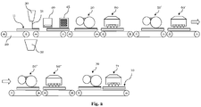
- Fig. 2 schematically shows a coating system for coating carrier plates ii.
- the carrier plates are cut and profiled after coating in a separate profiling line (not shown).
- the support plates ii have for example a thickness between 3 and 20 mm, a length (in the transport direction of the plant Fig. 2 seen) of 150 - 200 cm and a width of 125 - 210 cm.
- any other plate dimensions for the carrier plates can be used, which are cut at the end of the process in the desired shape and size.
- the in the Fig. 2 schematically shows a coating system for coating carrier plates ii.
- the carrier plates are cut and profiled after coating in a separate profiling line (not shown).
- the support plates ii have for example a thickness between 3 and 20 mm, a length (in the transport direction of the plant Fig. 2 seen) of 150 - 200 cm and a width of 125 - 210 cm.
- any other plate dimensions for the carrier plates can be used, which are cut at the end of
- Stations of the system shown are not meant to be exhaustive, but are only illustrative of the explanation of the method according to the invention.
- further processing stations may be provided, such as further drying stations, stations for applying primers, stations for applying putty, control and monitoring devices, etc.
- the carrier plates n are z. B. transported by roller conveyor 20 through the coating system.
- a primer mass is applied by means of a liquid curtain 31 of coating material on the front side (main side) of the carrier plates ii.
- the liquid curtain 31 extends over the entire plate width and the Plates are transported through this curtain and coated.
- a collection container 32 into which the liquid curtain falls when no plate is passed through the curtain, such as at the gap between two successive plates.
- an aqueous acrylate dispersion is preferably used as the coating material for the primer.
- the applied primer is dried with hot air, ie the water is removed from the aqueous acrylate dispersion. After drying the primer, a decorative layer is printed on the primer by means of a digital printing system 45.
- this decorative layer can imitate a real wood, but today's commercially available digital printing systems are capable of printing virtually any desired decor or pattern on the plates.
- a printing ink which can be polymerized by means of radiation ie a printing ink which is based on a polymerisable acrylate and / or N-vinylcaprolactam, is used in the printing system 45.
- the representation of the digital printing installation 45 is only purely schematic and that such printing installations as a rule consist of several stations.
- the material is chosen so that it has a Martens hardness Msi of 0.5 - 120 N / mm 2 after curing.
- the plant 50 is a roller application system and is capable of a layer thickness of about 40 - where ium apply in one operation.
- the applied layer of liquid radiation-curable aliphatic acrylate is at least partially cured by means of UV radiation.
- a second system 50 ' for applying a second layer of the same liquid, radiation-curable acrylate, as that of the first layer.
- the station 50 ' is a roller application station, which usually layer thicknesses of 30 - where ium able to apply is.
- this second layer is at least partially cured by UV radiation.
- a third layer of the same liquid, radiation-curable acrylate is applied and at least partially cured in the third radiation station 60" by means of UV radiation.
- a third coating installation 50 " a third layer of the same liquid, radiation-curable acrylate is applied and at least partially cured in the third radiation station 60" by means of UV radiation.
- a first elastic layer Si having a thickness of about 150 ⁇ m is present at the exit of the last radiation station 60 ".A layer of liquid, radiation-curable acrylate which is selected such that after hardening, it has a Marten hardness Ms2 which is greater than the Marten hardness of the first elastic layer and is preferably 5 to 300 N / mm 2 Fig. 2
- Ms2 Marten hardness
- Fig. 2 by way of example, only one application system 70 and one station 71 for radiation curing are shown, however, several systems can also be provided for the second layer S2, depending on the desired final thickness of the layer of S2.
- a panel coated according to the invention which can be further processed as desired.
Abstract
Die vorliegende Erfindung betrifft ein Paneel (10) sowie ein Verfahren zur Herstellung eines derartigen Paneels mit einer Trägerplatte (11), die eine Vorderseite und eine Rückseite aufweist, und wobei die Trägerplatte (11) zumindest an der Vorderseite ein Schichtsystem aufweist, das aus verschiedenen Polymerschichten mit unterschiedlichen Härtewerten aufgebaut ist.The present invention relates to a panel (10) and a method for producing such a panel having a support plate (11) having a front and a back, and wherein the support plate (11) at least on the front side of a layer system consisting of various Polymer layers is constructed with different hardness values.
Description
Die vorliegende Erfindung betrifft ein Paneel, insbesondere ein Wand-, Decken- oder Fußbodenpaneel, mit einer verbesserten Oberflächenbeschichtung, sowie ein Verfahren zu dessen Herstellung.The present invention relates to a panel, in particular a wall, ceiling or floor panel, with an improved surface coating, and a method for its production.
Aus dem Stand der Technik ist eine Vielzahl von Paneelen für Wand-, Decken- oder Fußbodenbeläge bekannt. Beispielsweise sind als Fußbodenbelag im Innenbereich sogenannte Laminatpaneele weit verbreitet. Laminatpaneele sind relativ kostengünstig und lassen sich gut verarbeiten. Sie basieren üblicherweise auf einer Trägerplatte aus MDF-oder HDF-Werkstoff, auf dessen Oberseite ein mit einem Melaminharz imprägniertes Dekorpapier aufgebracht ist. Durch Verpressen unter Einwirkung von Hitze und Druck härten die Harze aus, sodass eine hochabriebfeste Oberfläche entsteht. Zur Erhöhung der Abriebfestigkeit werden der Oberfläche vor dem Verpressen zudem häufig abriebfeste Partikel zugegeben, insbesondere Korund.From the prior art a variety of panels for wall, ceiling or floor coverings is known. For example, as a floor covering in the interior so-called laminate panels are widely used. Laminate panels are relatively inexpensive and can be processed well. They are usually based on a carrier plate made of MDF or HDF material, on top of which a decorative paper impregnated with a melamine resin is applied. By pressing under the action of heat and pressure, the resins harden, resulting in a highly abrasion-resistant surface. In order to increase the abrasion resistance, abrasion-resistant particles, in particular corundum, are frequently added to the surface prior to pressing.
Als Alternative zu Laminatpaneelen sind seit einiger Zeit hochwertige Paneele auf PVC-Basis bekannt und werden unter dem Begriff LVT (Luxury Vinyl Tiles) vertrieben. Beispielsweise ist aus der
Aus der
In neuerer Zeit setzen sich am Markt LVT-Paneele durch, die eine härtere PVC-Platte mit einer Stärke von 4- 6 mm als Untergrund haben und auf die eine weiche PVC-Schicht mit den Merkmalen wie oben beschrieben aufgebracht ist. In die härtere Platte werden spezielle Profile als Kopplungsmittel gefräst. Auf diese Weise lassen sich die Einzelpaneele leicht zu einer Fläche verlegen.More recently, LVT panels have become established on the market, having a harder PVC plate 4-6 mm thick as a substrate and having a soft PVC layer applied to them as described above. In the harder plate special profiles are milled as a coupling agent. In this way, the individual panels can be easily laid to a surface.
In einer Weiterentwicklung der oben beschriebenen Laminatpaneele wurden sogenannte direktbedruckte Paneele entwickelt. Bei diesen direktbedruckten Paneelen kommen in der Regel keine Papiere oder Folien mehr zur Anwendung, insbesondere kein Dekorpapier. Die Dekorschicht wird vielmehr unter Verwendung von Dispersionsfarben mittels eines Tiefdruckverfahrens direkt auf die Oberfläche der Trägerplatte gedruckt, welche üblicherweise einer geeigneten Vorbehandlung unterzogen wird. Insbesondere wird vor dem Drucken mittels Walzenapplizierung eine Grundierung aufgetragen. Nach Trocknen der Dekorschicht werden dann mehrere Harzschichten aufgetragen und ausgehärtet. Die Harzschichten dienen dabei als Schutzschicht sowie als abriebfeste Oberfläche. Auch hier werden häufig abriebfeste Partikel, wie etwa Korund, zugegeben, um die Abriebfestigkeit weiter zu erhöhen.In a further development of the laminate panels described above, so-called directly printed panels have been developed. In these direct-printed panels usually no papers or films are used more, especially no decorative paper. Rather, the decorative layer is printed using disperse dyes by means of a gravure printing process directly onto the surface of the support plate, which is usually subjected to a suitable pretreatment. In particular, a primer is applied by means of roll application prior to printing. After drying the decorative layer then several resin layers are applied and cured. The resin layers serve as a protective layer and as an abrasion-resistant surface. Again, abrasion-resistant particles, such as corundum, are often added in order to further increase the abrasion resistance.
Aus der
Die genannten Paneele aus dem Stand der Technik haben abhängig von ihrem Aufbau, dem verwendeten Herstellungsverfahren und der verwendeten Materialien jeweils eigene Vor- und Nachteile. Laminatpaneele sind beispielsweise in der Regel einfach zu verlegen, bieten die Möglichkeit qualitativ hochwertige und beliebige Dekore zu realisieren und sind zudem sehr strapazierfähig. Nachteilig sind jedoch typischerweise die akustischen Eigenschaften von Laminatpaneelen, die insbesondere bei Verwendung als Fußbodenbelag lästige Laufgeräusche verursachen. Verantwortlich dafür ist die sehr harte Melaminschicht auf der Laminatoberfläche. Diese Melaminoberfläche wird zudem als kalt und unangenehm empfunden. Beläge auf PVC-Basis haben hervorragende akustische Eigenschaften und zudem eine angenehme Haptik und fühlen sich warm und relativ weich an, was bei vielen Anwendungen, etwa als Fußbodenbelag in einem Badezimmer, wünschenswert ist. Um jedoch optisch qualitativ hochwertige Oberflächen zu erzeugen, müssen derartige PVC-Böden relativ aufwendig verarbeitet werden und sind damit erheblich teurer als übliche Laminatpaneele, jedenfalls wenn sie vergleichbare optische Qualität aufweisen sollen. Von Nachteil ist bei PVC-Paneelen, dass in der weichen Oberfläche bei intensiver Nutzung schnell tiefe Kratzer entstehen, die das optische Bild stören. Von Nachteil ist ferner, dass PVC-Böden aus ökologischer Sicht nicht unbedenklich sind. Sie enthalten gesundheitsschädigende Weichmacher und Chlor ist im Brandfall bekanntermaßen sehr gefährlich (z.B. Chlordioxinbildung).The prior art panels have their own advantages and disadvantages, depending on their construction, the manufacturing method used and the materials used. For example, laminate panels are usually easy to lay, offer the opportunity to realize high-quality and any decors and are also very durable. However, the disadvantage is typically the acoustic properties of laminate panels, which cause annoying operating noise, especially when used as a floor covering. Responsible for this is the very hard melamine layer on the laminate surface. This melamine surface is also perceived as cold and unpleasant. PVC-based coverings have excellent acoustic properties and also a pleasant feel and feel warm and relatively soft, which is desirable in many applications, such as flooring in a bathroom. However, in order to produce optically high-quality surfaces, such PVC floors must be processed relatively expensive and are thus considerably more expensive than conventional laminate panels, at least if they are to have comparable optical quality. A disadvantage of PVC panels is that in the soft surface during intensive use quickly deep scratches occur that disturb the optical image. Another disadvantage is that PVC floors are ecologically unobjectionable. They contain harmful plasticizers and chlorine is known to be very dangerous in case of fire (eg chlorine dioxin formation).
Direkt bedruckte Paneele räumen einige der Nachteile von Laminatpaneelen aus und benötigen etwa kein mit Melaminharz getränktes Dekorpapier, wodurch die Herstellung vereinfacht werden kann. Jedoch haben sie, was die akustischen Eigenschaften angeht sowohl was die Haptik angeht, ähnliche Nachteile wie Laminatpaneele.Directly printed panels eliminate some of the disadvantages of laminate panels and do not require melamine resin soaked decor paper, which can simplify manufacturing. However, as far as the acoustic properties are concerned, they have similar drawbacks as laminate panels, both in terms of their feel.
Im Lichte dieser bekannten Paneele bzw. Beläge stellt sich die vorliegende Erfindung die Aufgabe, ein Paneel, insbesondere ein Wand-, Decken- oder Fußbodenpaneel bereitzustellen, das möglichst viele der verschiedenen Vorteile der bekannten Paneele aufweist, dabei jedoch die inhärent vorhandenen Nachteile der verschiedenen Paneele möglichst minimiert. Zudem stellt sich weiter die Aufgabe, dass ein solches Paneel kostengünstig und auf relativ einfache Weise hergestellt werden kann. Eine weitere Aufgabe liegt in der Bereitstellung derartiger Paneele, die eine gute Haltbarkeit haben und mit denen die Realisierung von qualitativ hochwertigen dekorativen Mustern möglich ist.In the light of these known panels or coverings, the present invention has the object to provide a panel, in particular a wall, ceiling or floor panel, which has as many of the various advantages of the known panels, but the inherent disadvantages of the various panels minimized as possible. In addition, the task continues that such a panel can be produced inexpensively and in a relatively simple manner. Another object is to provide such panels which have a good durability and with which the realization of high-quality decorative patterns is possible.
Diese und andere Aufgaben, die beim Lesen der vorliegenden Beschreibung noch genannt werden oder vom Fachmann erkannt werden können, werden mit einem Paneel nach Anspruch 1 und einem entsprechenden Verfahren zur Herstellung eines derartigen Paneels nach Anspruch 24 gelöst.These and other objects, which will become apparent upon reading the present specification or which may be recognized by those skilled in the art, are achieved by a panel according to claim 1 and a corresponding method of making such a panel according to claim 24.
Gemäß der vorliegenden Erfindung wird ein Paneel, wie etwa ein Wand-, Decken-, aber insbesondere ein Fußbodenpaneel bereitgestellt, das eine Trägerplatte mit einer Vorderseite und einer Rückseite umfasst, wobei zumindest an der Vorderseite ein Schichtsystem vorgesehen ist. Mit Vorderseite soll hierunter diejenige Seite verstanden werden, die im verlegten Zustand des Paneels, beispielsweise in Form eines Fußbodens, die Nutzseite darstellt die zum Betrachter weist. Die Trägerplatten können optional aufgeteilt werden in Paneele. An ihren Seitenkanten können die Paneele über Kopplungsmittel verfügen, wie insbesondere in Form von Nut- und Federelementen, wie sie aus dem Bereich der Fußbodenlaminatpaneele bekannt sind. Besonders geeignete Nut- und Federelemente erlauben ein Verbinden mehrerer gleichartiger Paneele in Richtungen parallel zur Vorderseite als auch senkrecht zur Vorderseite durch Formschluss. Paneele können natürlich auch einzeln dem Verfahrensablauf unterzogen werden, wenn diese Vorgehensweise auch weniger wirtschaftlich ist. Erfindungsgemäß weist das Schichtsystem von der Vorderseite ausgehend eine erste elastische Schicht auf, die aus einem Polymer besteht ist und im Folgenden als Schicht Si bezeichnet wird. Diese erste Polymerschicht weist erfindungsgemäß eine Dicke von 20 - 600 ium auf und hat eine Martenshärte Msi von 0,5 - 120 N/mm2, vorzugsweise zwischen 2 und 50 N/mm2, noch mehr bevorzugt zwischen 2 und 40 N/mm2, und am meisten bevorzugt zwischen 2 und 30 N/mm2, sie ist mithin weich elastisch. Über dieser ersten elastischen Schicht wird eine zweite Schicht S2 vorgesehen, die eine Dicke von nur 10 - 200 ium hat und eine Martenshärte Ms2, die größer ist als die Martenshärte der ersten elastischen Schicht, d. h. Ms2 > Msi. Die Martenshärte Ms2, bestimmt an der Paneeloberfläche, liegt zwischen 5 - 300 N/mm2, bevorzugt bei 15-150 N/mm2, noch mehr bevorzugt zwischen 20 und 100 N/mm2 und am meisten bevorzugt zwischen 25 und 90 N/mm2..According to the present invention, there is provided a panel, such as a wall, ceiling, but especially a floor panel comprising a backing plate having a front side and a back side, wherein a layer system is provided at least at the front side. The term front should be understood to mean that side which, in the installed state of the panel, for example in the form of a floor, represents the useful side facing the viewer. The carrier plates can optionally be divided into panels. At their side edges, the panels may have coupling means, such as in particular Shape of tongue and groove elements, as they are known in the field of floor laminate panels. Particularly suitable tongue and groove elements allow a connection of several similar panels in directions parallel to the front and perpendicular to the front by positive engagement. Of course, panels can also be subjected to the process individually, if this procedure is also less economical. According to the invention, the layer system has, starting from the front side, a first elastic layer which consists of a polymer and is referred to below as layer Si. According to the invention, this first polymer layer has a thickness of 20-600 μm and has a Martens hardness Msi of 0.5-120 N / mm 2 , preferably between 2 and 50 N / mm 2 , even more preferably between 2 and 40 N / mm 2 , and most preferably between 2 and 30 N / mm 2 , it is therefore soft elastic. Over this first elastic layer, a second layer S2 is provided which has a thickness of only 10-200 μm and a Martens hardness Ms2 which is greater than the Marten hardness of the first elastic layer, ie Ms2> Msi. Marten hardness Ms2, determined at the panel surface, is between 5 - 300 N / mm 2 , preferably 15-150 N / mm 2 , even more preferably between 20 and 100 N / mm 2 and most preferably between 25 and 90 N / mm 2 ..
Der erfindungsgemäße Aufbau des Schichtsystems des Paneels hat zur Folge, dass sich die Oberfläche des derart beschichteten Paneels - unabhängig vom Material der Trägerplatte - relativ weich anfühlt und einen für das menschliche Empfinden angenehm warmen haptischen Eindruck hat. Insbesondere hat das Vorsehen der dicken elastischen Schicht Si erhebliche akustische Vorteile. Im Vergleich zu einem Laminat-Referenzboden führt das erfindungsgemäße Schichtsystems zu einer signifikanten Geräuschdämpfungswirkung beim Begehen. So wird nach IHD-W 431 für einen Laminat-Referenzboden eine Lautheit von 26 Sone ermittelt. Der mit einer elastischen Schicht Si und und einer Schicht S2 versehene Boden weist ein Verbesserungsmaß von 10 - 70 % zu diesem Referenzboden auf. Ein PVC (LVT)-Boden wurde im Vergleich zur Referenz mit einem Verbesserungsmaß von 40 % gemessen.The inventive structure of the layer system of the panel has the consequence that the surface of the thus coated panel - regardless of the material of the support plate - feels relatively soft and has a pleasantly warm to the human sensation haptic impression. In particular, the provision of the thick elastic layer Si has considerable acoustic advantages. In comparison to a laminate reference floor, the layer system according to the invention leads to a significant noise damping effect when walking. Thus, according to IHD-W 431, a loudness of 26 sone is determined for a laminate reference floor. The floor provided with an elastic layer Si and a layer S2 has an improvement of 10 - 70% to this reference bottom. A PVC (LVT) bottom was measured at 40% improvement compared to the reference.
Als Materialien für die Trägerplatte kommen eine Vielzahl von unterschiedlichen Werkstoffen in Frage, da die relevanten physikalischen Eigenschaften des erfindungsgemäßen Paneels im Wesentlichen durch das aufgebrachte Schichtsystem bestimmt werden. Generell bevorzugt ist die Trägerplatte des erfindungsgemäßen Paneels daher beispielsweise eine MDF-Platte, HDF-Platte, PVC-Platte, Zementfaser-Platte, WPC-Platte (wood powder composite), eine thermoplastische Recyclingplatte, eine Holzplatte, eine Holzfurnier-Platte oder etwa eine Parkettplatte, wie etwa eine Fertigparkettplatte. Wie eingangs erwähnt, kann die Trägerplatte vorteilhaft an ihren Seiten über Kopplungsmittel in Form von Nut- und Federelementen verfügen, sodass die erfindungsgemäßen Paneele einfach beispielsweise auf einem Fußboden zu einem Belag verlegt werden können.Suitable materials for the carrier plate are a variety of different materials in question, since the relevant physical properties of the panel according to the invention are essentially determined by the applied layer system. In general, the support plate of the panel according to the invention is therefore preferably, for example, an MDF board, HDF board, PVC board, cement fiber board, wood powder composite (WPC) board, a thermoplastic recycling board, a wood board, a wood veneer board or about one Parquet plate, such as a Fertigparkettplatte. As mentioned above, the support plate can advantageously have at their sides via coupling means in the form of tongue and groove elements, so that the panels according to the invention can be easily laid, for example on a floor to a covering.
Generell bevorzugt sind die Materialien für die Schichten Si und S2 (und S3) Acylatsysteme bzw. basieren auf Acrylaten. Unter einem Acrylatsystem wird hierin ein polymerisationsfähiges Gemisch von doppelbindungshaltigen mono-, di- und mehrfachfunktionellen acrylsäurebasierenden Verbindungen verstanden. Typische Vertreter sind beispielsweise Dipropylenglycoldiacrylat, i,6-Hexandioldiacrylat, Polyurethan-Acrylsäureester, Polyester-Acrylsäurester wie sie im Produktionsprogramm der Firma BASF unter dem Handelsnamen LaromerTM - Typen am Markt erhältlich sind.In general, the materials for the layers Si and S2 (and S3) are preferably acylate systems or are based on acrylates. An acrylate system is understood here to mean a polymerizable mixture of double bond-containing mono-, di- and polyfunctional acrylic acid-based compounds. Typical representatives are for example Dipropylenglycoldiacrylat, i, 6-Hexandioldiacrylat, polyurethane acrylic acid ester, polyester acrylic acid ester as they are in the production program of the company BASF under the trade name LaromerTM - types on the market available.
Schicht Si ist vorzugsweise ein Polymer auf Basis eines radikalisch polymerisierbaren Oligomers und/ oder Oligomergemisches. Bevorzugt basiert es auf strahlenhärtbaren Acrylatoligomeren (Acrylatsystem). Die Oligomere werden so ausgewählt, dass die Schicht möglichst dämpfende Eigenschaften hat, gekennzeichnet durch die Martenshärte vorzugsweise 0,5 - 120 N/mm2, besonders bevorzugt 2 - 50 N/mm2. Eine solche Oligomerformulierung besteht beispielsweise aus einem oder mehreren ungesättigten Acrylaten, die eine Polyester-, Polyether und/ oder Polyurethanstruktur enthalten, mit einer Funktionalität von 1 - 4, bevorzugt < 2. Handelsübliche Beispiele dafür sind das Laromer PO 43 F, das Laromer UA 9033 oder das Laromer UA 19 T der BASF. Die Oligomermischung kann weiterhin niedrigviskose Acrylester mit einer Funktionalität von 1 - 4, bevorzugt mit einer Funktionalität von 1 - 2 enthalten. Handelsübliche Beispiele dafür sind das Laromer LR 8887, Laromer DPGDA, Laromer TPGDA der BASF. Für die Härtung mittels UV-Strahlung werden Fotoinitiatoren wie z.B. Mono- oder Bisacylphosphinoxide, Alphahydroxyketone, Benzophenonderivate, Benzildimethyketal oder Phenylglyoxalate benötigt. Die Formulierung kann ferner Additive wie Netzmittel, Entschäumer, anorganische oder organische Füllstoffe enthalten. Als Additive können beispielsweise Polyacrylate, Silikone, Talkum, Bariumsulfat, Kreide, Kieselsäure oder auch Polyharnstoffderivate verwendet werden.Layer Si is preferably a polymer based on a free-radically polymerizable oligomer and / or oligomer mixture. It is preferably based on radiation-curable acrylate oligomers (acrylate system). The oligomers are selected so that the layer has the most damping properties, characterized by the Marten hardness preferably 0.5 to 120 N / mm 2 , particularly preferably 2 to 50 N / mm 2 . Such an oligomer formulation consists for example of one or more unsaturated acrylates containing a polyester, polyether and / or polyurethane structure with a functionality of 1-4, preferably <2. Commercially available examples thereof are the Laromer PO 43 F, the Laromer UA 9033 or the Laromer UA 19 T from BASF. The oligomer mixture may further contain low-viscosity acrylic esters having a functionality of 1-4, preferably having a functionality of 1-2. Commercially available examples of these are the Laromer LR 8887, Laromer DPGDA, Laromer TPGDA from BASF. For curing by means of UV radiation photoinitiators such as mono- or Bisacylphosphinoxide, Alphahydroxyketone, Benzophenonderivate, Benzildimethyketal or Phenylglyoxalate needed. The formulation may further contain additives such as wetting agents, defoamers, inorganic or organic fillers. As additives, for example, polyacrylates, silicones, talc, barium sulfate, chalk, silicic acid or else polyurea derivatives can be used.
Das Material für die zweite Schicht S2 ist vorzugsweise basierend auf einem radikalisch polymerisierbaren Acrylatoligomer (Acrylatsystem) oder einer radikalisch polymerisierbaren Acrylatmischung, bestehend aus einem oder mehreren ungesättigten Acrylaten (Acrylatsystem), eine Polyester, Polyether- und/ oder Polyurethanstruktur enthaltend, mit einer Funktionalität von 1 - 8, bevorzugt 3 - 6. Beispiele dafür sind das Laromer PE 9074, Laromer 8863 oder Laromer LR 8987 als Lackrohstoffe der BASF. Bevorzugt enthalten diese Acrylatmischungen weiterhin niedrigviskose Acrylester mit einer Funktionalität von 1 - 6, bevorzugt mit einer Funktionalität von 2 - 4. Beispielsweise können folgende Rohstoffe der BASF mit den Handelsbezeichnungen Laromer HDDA, Laromer TMPTA, Laromer PPTTA eingesetzt werden. Im Falle UV-vernetzender Systeme werden Fotoinitiatoren wie z.B. Mono- bzw. Bisacylphosphinoxide, Alphahydroxyketone, Benzophenonderivate, Benzildimethylketal oder Phenylglyoxylate zugesetzt. Weiterhin können Additive wie Netzmittel, Entschäumer, Mattierungsmittel sowie anorganische oder organische Füllstoffe zugesetzt werden, beispielsweise Polyacrylate, Silikone, Talkum, Bariumsulfat, Kreide,The material for the second layer S2 is preferably based on a free-radically polymerizable acrylate oligomer (acrylate system) or a free-radically polymerizable acrylate mixture consisting of one or more unsaturated acrylates (acrylate system) containing a polyester, polyether and / or polyurethane structure having a functionality of 1-8, preferably 3-6. Examples of these are the Laromer PE 9074, Laromer 8863 or Laromer LR 8987 as coating raw materials from BASF. These acrylate mixtures furthermore preferably contain low-viscosity acrylic esters having a functionality of 1-6, preferably having a functionality of 2-4. For example, the following raw materials from BASF with the trade names Laromer HDDA, Laromer TMPTA, Laromer PPTTA can be used. In the case of UV-crosslinking systems, photoinitiators such as mono- or bisacylphosphine oxides, alphahydroxy ketones, benzophenone derivatives, benzil dimethyl ketal or phenyl glyoxylates are added. Furthermore, additives such as wetting agents, defoamers, matting agents and inorganic or organic fillers may be added, for example polyacrylates, silicones, talc, barium sulfate, chalk,
Kieselsäure oder auch Polyharnstoffderivate. Die Oligomeren werden so ausgewählt, dass die Oberflächenhärte in den oben erwähnten Bereichen liegt. Weiterhin wird die Rohstoffauswahl so getroffen, dass die Schicht S2 neben dämpfenden Eigenschaften vor allem eine hohe Verschleißfestigkeit bringt (Kratzfestigkeit, Mikrokratzfestigkeit, Abriebfestigkeit). Der Fachmann weiß, dass diese Eigenschaften über die Netzwerkdichte und Modifizierungen beispielsweise mit Nanopartikeln erreicht wird.Silica or polyurea derivatives. The oligomers are selected so that the surface hardness is in the above-mentioned ranges. Furthermore, the raw material selection is made so that the layer S2 in addition to damping properties, especially a high wear resistance brings (scratch resistance, micro scratch resistance, abrasion resistance). The person skilled in the art knows that these properties are achieved via the network density and modifications, for example with nanoparticles.
Die Dicke der Trägerplatte liegt vorzugweise zwischen 3 und 20 mm, mehr bevorzugt zwischen 4 und 15 mm, noch mehr bevorzugt zwischen 3 und 12 mm und am meisten bevorzugt zwischen 4 und 10 mm. Abhängig von Verwendungszweck und aufgebrachtem Dekor (falls vorhanden) sind unterschiedliche Formen möglich. Soll das Paneel beispielsweise ein Echtholzdekor imitieren und als Fußboden- oder Wandpaneel verlegt werden, ist eine rechteckige Grundform der Trägerplatte bzw. des Paneels vorteilhaft, beispielsweise in einer Rechteckform von 1 ½ - 2 m Länge und 10 - 30 cm Breite.The thickness of the backing plate is preferably between 3 and 20 mm, more preferably between 4 and 15 mm, even more preferably between 3 and 12 mm and most preferably between 4 and 10 mm. Depending on the purpose and applied decor (if available) different shapes are possible. If the panel, for example, imitate a real wood decor and laid as a floor or wall panel, a rectangular basic shape of the support plate or the panel is advantageous, for example in a rectangular shape of 1 ½ - 2 m in length and 10 - 30 cm wide.
Wie eingangs erwähnt bestimmen sich die relevanten physikalischen Eigenschaften der Oberfläche des erfindungsgemäßen Paneels im Wesentlichen durch das erfindungsgemäße Schichtsystem. Die dicke erste elastische Schicht Si ist für die akustischen Eigenschaften des Paneels maßgebend. Grundsätzlich bevorzugte Härtewerte nach Martens für die Schicht Si liegen dabei wie oben erwähnt bei 0,5 - 120 N/mm2, besonders bevorzugt zwischen 2 und 50 N/mm2, noch mehr bevorzugt zwischen 2 und 40 N/mm2, und am meisten bevorzugt zwischen 2 und 30 N/mm2. Die zweite Schicht S2 muss in jedem Fall eine größere Härte aufweisend als die erste Schicht und sollte wie oben erwähnt bevorzugt in einem Bereich von zwischen 5 - 300 N/mm2, besonders bevorzugt bei 15 - 150 N/mm2, noch mehr bevorzugt zwischen 20 und 100 N/mm2 und am meisten bevorzugt zwischen 25 und 90 N/mm2 liegen. Dem Fachmann ist klar, dass auch wenn sich die genannten Bereichsangaben für die bevorzugten Härten von Msi und Ms2 teilweise überschneiden es im Wesentlichen darauf ankommt, dass Ms2 größer ist als Msi.As mentioned above, the relevant physical properties of the surface of the panel according to the invention are essentially determined by the layer system according to the invention. The thick first elastic layer Si is decisive for the acoustic properties of the panel. Basically preferred hardness values according to Martens for the layer Si lie, as mentioned above, at 0.5-120 N / mm 2 , more preferably between 2 and 50 N / mm 2 , even more preferably between 2 and 40 N / mm 2 , and on most preferably between 2 and 30 N / mm 2 . The second layer S2 must in any case have a greater hardness than the first layer and, as mentioned above, should preferably be in a range of between 5 - 300 N / mm 2 , more preferably 15 - 150 N / mm 2 , even more preferably between 20 and 100 N / mm 2, and most preferably between 25 and 90 N / mm 2 . It is clear to the person skilled in the art that even if the specified range data For the preferred hardnesses of Msi and Ms2 partially overlapping it essentially depends on Ms2 being larger than Msi.
Die Bestimmung der Martenshärte ist dem Fachmann grundsätzlich bekannt. Bei der Entwicklung der vorliegenden Erfindung wurde hierzu mit einem Taber Abraser Prüfgerät 5151 der Firma Taber Industries gearbeitet. Jeweils nach 200 Umdrehungen mit S-41-Schleifpapier wurden die Härte und Spurentiefe der Proben bestimmt. Die Bestimmung der Martenshärte (registrierende Härteprüfung unter Prüfkrafteinwirkung) wurde gemäß DIN EN ISO 14577 durchgeführt. Als Prüfgerät wurde ein "Fischerscope Hioo" der Helmut Fischer GmbH eingesetzt. Folgende Prüfparameter wurden verwendet: Maximalkraft: 50/30 mN sowie Messdauer: 20 Sekunden. Die Bestimmung der Spurtiefe wurde mit einem mechanischen Tastschnittmessgerät durchgeführt. Als Prüfgerät wurde ein Perthometer 53P der Firma Perthen verwendet.The determination of Martens hardness is known in principle to the person skilled in the art. For the development of the present invention, a Taber Abraser tester 5151 from Taber Industries was used for this purpose. After every 200 revolutions with S-41 abrasive paper, the hardness and trace depth of the samples were determined. The determination of Martens hardness (registering hardness test under test force effect) was carried out according to DIN EN ISO 14577. The tester used was a "Fischerscope Hioo" made by Helmut Fischer GmbH. The following test parameters were used: maximum force: 50/30 mN and measuring time: 20 seconds. The determination of the track depth was carried out with a mechanical stylus meter. The tester was a Perthometer Perthometer 53P.
Bei der Vermessung der Proben hat sich gezeigt, dass es wahrscheinlich aufgrund der verwendeten relativ weichen Materialien zu mehr oder weniger großen Abweichungen in der Härte einer gegebenen Schichttiefe kommt. Es ist daher notwendig an mehreren Punkten zu messen, um über eine Mittelwertbildung aussagekräftige, repräsentative Daten zu erhalten. Bei den vorgenommenen Messungen wurden die Härte sowie die Spurentiefe nach 200 Umdrehungen des Schleifpapiers jeweils an vier Stellen gemessen. Es hat sich gezeigt, dass vier Messpunkte in den meisten Fällen eine ausreichende Genauigkeit bieten. Selbstverständlich erhält man noch genauere Messergebnisse, wenn man mehr als vier Messpunkte verwendet, wie beispielsweise acht.When measuring the samples, it has been found that, due to the relatively soft materials used, it is probable that there will be more or less large variations in the hardness of a given layer depth. It is therefore necessary to measure at several points in order to obtain meaningful, representative data by averaging. In the measurements made, the hardness and the trace depth were measured at four points after 200 revolutions of the abrasive paper. It has been shown that four measurement points provide sufficient accuracy in most cases. Of course you get even more accurate results when you use more than four measurement points, such as eight.
Vorzugsweise liegt die Dicke der elastischen Schicht Si in einem Bereich von 20 - 600 ium, mehr bevorzugt von 40 bis 500 ium, noch mehr bevorzugt von 80 - 450 ium und am meisten bevorzugt von 120 - 240 ium. Die zweite Schicht S2 hat unabhängig von der Dicke der ersten Schicht bevorzugt eine Dicke von 10 - 180 ium, noch mehr bevorzugt von 20 - 100 ium und am meisten bevorzugt von 30 - 80 ium. Dabei ist es dem Fachmann klar, dass je dicker die erste elastische Schicht Si gewählt wird, umso elastischer die Eigenschaften der Oberfläche des so beschichteten Paneels sein können. Die Schicht Si wird vorzugsweise nacheinander in Teilschritten insbesondere über mehrere Walzenwerke mit jeweiligem Angelieren nach den Walzenauftragswerken aufgetragen werden. Unter Angelieren wird verstanden, dass in der jeweiligen Schicht eine radikalische Polymerisation durch Strahlung beispielsweise mittels UV initiiert wird, diese Polymerisation aber schnell zum Abbruch gebracht um so die Haftung der nächsten Schichten sicher zu stellen. Mit anderen Worten, die Teilschichten werden jeweils nicht vollständig ausgehärtet, sondern jeweils nur teilweise. Auf diese Weise wird u.a. auch die Haftung der Teilschichten aufeinander erhöht. Die Schicht Si kann alternative aber auch in einem einzigen Schritt aufgetragen werden.Preferably, the thickness of the elastic layer Si is in a range of 20-600 μm, more preferably 40-500 μm, even more preferably 80-450 μm, and most preferably 120-240 μm. The second layer S2 preferably has a thickness of 10-180 μm, more preferably still, regardless of the thickness of the first layer 20-100 μm and most preferably from 30-80 μm. It is clear to those skilled in the art that the thicker the first elastic layer Si is chosen, the more elastic the properties of the surface of the thus coated panel can be. The layer Si is preferably applied sequentially in partial steps, in particular over a plurality of roller units with respective fishing after the roller applicators. By "fishing" is meant that in the respective layer a radical polymerization is initiated by radiation, for example by means of UV, but this polymerization quickly brought to a halt so as to ensure the adhesion of the next layer. In other words, the partial layers are not completely cured, but only partially. In this way, inter alia, the adhesion of the sub-layers is increased to each other. Alternatively, the layer Si can be applied in a single step.
Vorzugsweise ist zwischen der Vorderseite und der Schicht Si weiter eine Dekorschicht vorgesehen, die eine Druckfarbe (Tinte) umfasst, bzw. aus dieser Druckfarbe besteht. Der Begriff "Druckfarbe" wird hierin generisch verwendet und soll keine einzelne Farbe sondern Druckfarbe im Allgemeinen bezeichnen: beim digitalen Vierfarbdruck besteht die Druckfarbe z.B. aus vier verschiedenen Farben (Cyan, Magenta, Gelb, Schwarz), aus denen das Druckbild durch Farbmischung der aufgespritzten Farbtröpfchen erzeugt wird. Beim indirekten Tiefdruck wird das Dekorbild bekanntermaßen über rotierende Druckzylinder erzeugt. Mit den Druckzylindern werden dekorspezifische Mischfarben aufgetragen. Grundsätzlich ist es bei der vorliegenden Erfindung bevorzugt, dass die Schichten Si und S2 im Wesentlichen transparent sind, um als Schutz für eine darunterliegende Dekorschicht dienen zu können.Preferably, between the front side and the layer Si further a decorative layer is provided, which comprises a printing ink (ink), or consists of this printing ink. The term "printing ink" is used generically herein and is not meant to refer to a single color but to printing ink in general: in the case of digital four-color printing, the ink consists e.g. from four different colors (cyan, magenta, yellow, black), from which the printed image is created by mixing the sprayed-on paint droplets. In indirect gravure printing the decorative image is known to be generated by rotating impression cylinder. The printing cylinders are used to apply decor-specific mixed colors. In principle, it is preferred in the present invention that the layers Si and S2 are substantially transparent in order to be able to serve as protection for an underlying decorative layer.
Üblicherweise kommen im Stand der Technik als Druckfarbe Dispersionsfarben zum Einsatz, wie insbesondere Acrylfarben. Diese Dispersionsfarben werden regelmäßig bei dem üblicherweise zum Einsatz kommenden Tiefdruckverfahren verwendet. Dispersionsfarben sind Druckfarben, die in der Regel aus drei Hauptbestandteilen bestehen, nämlich a) einem Lösungsmittel (üblicherweise Wasser), b) Bindemittel in Form von Kunststoffpolymeren, die sich bei Verdunstung des Lösungsmittels zusammenlagern und einen feste Schicht bilden, sowie c) Farbpigmente zur Erzeugung der gewünschten Deckung und des gewünschten Farbtons. Die Härtung dieser Dispersionsfarben erfolgt also nicht durch eine Polymerisation, sondern durch ein Verflüchtigen des Lösungsmittels, da die Bindemittel bereits als Polymere vorliegen. Die in der Dispersion enthaltenen Polymere verbinden sich bei Verdunstung des Bindemittels auf rein physikalische Weise und bilden eine feste, geschlossene Schicht.In the prior art, emulsion paints are usually used as the printing ink, in particular acrylic paints. These emulsion paints are regularly used in the usual Use coming gravure printing method used. Emulsion paints are printing inks, which generally consist of three main components, namely a) a solvent (usually water), b) binders in the form of plastic polymers, which collect on evaporation of the solvent and form a solid layer, and c) color pigments for production the desired coverage and the desired hue. The curing of these emulsion paints is thus not by a polymerization, but by a volatilization of the solvent, since the binders are already present as polymers. The polymers contained in the dispersion combine on evaporation of the binder in a purely physical way and form a solid, closed layer.
Es wurde im Zusammenhang mit der vorliegenden Erfindung überraschend festgestellt, dass verbesserte Hafteigenschaften von erfindungsgemäßen Schichtsystemen erreicht werden können, wenn im vorliegenden Fall anstelle der üblichen Dispersionsfarben polymerisierbare Druckfarben verwendet werden. Der positive Effekt ist besonders ausgeprägt, wenn die Druckfarbe der Dekorschicht und zumindest ein Teil der ersten elastischen Schicht Si gemeinsam ausgehärtet bzw. polymerisiert werden (wenn die Dekorschicht direkt aufgedruckt wird, wie etwa im Digitaldruck, besteht die Dekorschicht quasi aus der Druckfarbe). Unter Aushärtung bzw. Teil-Aushärtung (Angelieren) einer Polymerschicht bzw. einer polymerisierbaren Druckfarbe wird hierbei die chemische Reaktion verstanden, die bei der Polymerisation stattfindet. Hiervon zu unterscheiden ist das Trocknen derartiger Schichten, bei dem lediglich das Lösungsmittel, wie etwa der Wassergehalt einer Dispersionsfarbe, verdunstet bzw. auf rein physikalische Weise reduziert wird. Durch die gemeinsame (Teil- )Aushärtung der polymerisierbaren Druckfarbe und der Materialien für die erste elastische Schicht erfolgt vermutlich eine chemische Vernetzung an der Grenzfläche der beiden Schichten, von der angenommen wird, dass sie für die verbesserte Haftung der Schichten insgesamt verantwortlich ist. Die herkömmlich verwendetenIt has surprisingly been found in connection with the present invention that improved adhesive properties of layer systems according to the invention can be achieved if in the present case polymerizable printing inks are used instead of the customary emulsion paints. The positive effect is particularly pronounced when the printing ink of the decorative layer and at least part of the first elastic layer Si are cured or polymerized together (if the decorative layer is printed directly, such as in digital printing, the decorative layer is quasi from the ink). Curing or partial curing (gelling) of a polymer layer or of a polymerizable printing ink is understood to mean the chemical reaction which takes place during the polymerization. To distinguish this is the drying of such layers, in which only the solvent, such as the water content of an emulsion paint, evaporated or reduced in a purely physical way. The combined (partial) curing of the polymerizable ink and the materials for the first elastic layer presumably results in chemical cross-linking at the interface of the two layers, which is believed to be responsible for the overall improved adhesion of the layers. The conventionally used
Dispersionsfarben weisen keine polymerisierbaren Acrylatsysteme auf, sodass keine derartige chemische Vernetzung zwischen Druckfarbe, also der Dekorschicht, und der elastischen Schicht stattfinden kann.Emulsion paints have no polymerizable acrylate systems, so that no such chemical crosslinking between printing ink, so the decorative layer, and the elastic layer can take place.
Allgemein bevorzugt sind die für die vorliegende Erfindung verwendeten Druckfarben daher polymerisierbare Druckfarben und insbesondere polymerisierbare Acrylatsysteme. Polymerisierbare Druckfarben erhalten als Hauptbestandteile Bindemittel, nämliche reaktive Doppelbindungen enthaltene Harze; Monomere bzw. Oligomere, wie etwa Acrylatmonomere und Acrylatoligomere; optional Fotoinitiatoren für strahlenhärtbare Druckfarben; Additive wie etwa Entschäumer, Verlaufsadditive, etc.; und Farbpigmente sowie Füllstoffe zur Erzielung bestimmter physikalisch technischer Eigenschaften. Generell bevorzugt sind die verwendeten Druckfarben für die vorliegende Erfindung weiter strahlenhärtbar, wie insbesondere durch UV-Strahlen härtbare Druckfarben. Besonders bevorzugt ist die Druckfarbe basierend auf einem polymerisierbaren Acrylat und/oder N-Vinylcaprolactam.Generally, the printing inks used for the present invention are therefore preferably polymerizable printing inks and in particular polymerizable acrylate systems. Polymerizable printing inks contain as main constituents binders, resins containing reactive double bonds; Monomers or oligomers, such as acrylate monomers and acrylate oligomers; optional photoinitiators for radiation-curable printing inks; Additives such as defoamers, leveling additives, etc .; and color pigments and fillers to achieve certain physical properties. In general, preferably, the printing inks used for the present invention are further radiation-curable, in particular by UV inks curable inks. Particularly preferred is the printing ink based on a polymerizable acrylate and / or N-vinylcaprolactam.
In einer weiteren Ausführungsform der vorliegenden Erfindung ist auf der Vorderseite unterhalb der Dekorschicht eine dritte elastische Schicht S3 vorgesehen, die eine Martenshärte Ms3 hat, wobei die Härte der dritten elastischen Schicht vorzugsweise gleich oder kleiner der Härte der ersten elastischen Schicht Si ist, d.h. Ms3 Msi. Auf diese Weise können besonders dicke Schichtsysteme mit entsprechend guten elastischen Eigenschaften erzeugt werden. Vorzugsweise sollte die Schicht S3 dabei eine Dicke von 10 - 300 ttm haben, mehr bevorzugt von 30 - 150 ttm und am meisten bevorzugt von 60 - 120 ttm. Für die Schicht S3 wird ein radikalisch polymerisierbares Acrylatgemisch verwendet wie sie auch für die Schicht Si vorgesehen sind und oben beschrieben wurden. Diese Oligomermischung wird vorzugsweise vor der Applikation mit Pigmenten versetzt um der Schicht eine deckende Farbe als Druckgrund zu geben, d.h. diese Schicht S3 sollte vorzugsweise nicht transparent sein um eine genügende Druckqualität zu erreichen. Die Dekorschicht, inkl. evtl. notwendiger Primer- undIn a further embodiment of the present invention, a third elastic layer S3 having a Marten hardness Ms 3 , wherein the hardness of the third elastic layer is preferably equal to or less than the hardness of the first elastic layer Si, ie Ms 3 ms. In this way, particularly thick layer systems can be produced with correspondingly good elastic properties. Preferably, the layer S3 should have a thickness of 10 - 300 tons, more preferably 30 - 150 tons and most preferably 60 - 120 tons. For the layer S3, a radically polymerizable acrylate mixture is used as they are also provided for the layer Si and described above. This oligomer mixture is preferably mixed with pigments prior to application in order to give the layer an opaque color as a printing substrate, ie this layer S3 should preferably not be transparent in order to achieve sufficient print quality. The decorative layer, incl. Possibly necessary primer and
Grundierungsschichten, wird dann auf diese zuvor aufgebrachte Schicht S3 aufgebracht. Der Vorteil dieser dritten Schicht S3 liegt darin, dass das Gesamtschichtsystem sehr dick gestaltet werden kann, ohne dass der optische Eindruck einer eventuell vorhandenen Dekorschicht beeinträchtigt wird, da zwischen einem Betrachter und der Dekorschicht nur die erste elastische Schicht Si und die zweite Schicht S2 liegt.Primer layers are then applied to this previously applied layer S3. The advantage of this third layer S3 is that the overall layer system can be made very thick without impairing the visual impression of a possibly present decorative layer, since only the first elastic layer Si and the second layer S2 lie between a viewer and the decorative layer.
Das erfindungsgemäße Schichtsystem hat weiter den Vorteil, dass keine weiteren Papier- oder Kunststofffolien an der Vorderseite des Paneels bzw. der Trägerplatte notwendig sind, wie es im Stand der Technik bei vielen Anwendungen notwendig war. Die Paneele können somit im Durchlauf in einer Anlage beschichtet werden und müssen nicht mit einer zuvor produzierten Papier- oder Kunststofffolie in Kontakt gebracht und verklebt werden.The layer system according to the invention has the further advantage that no further paper or plastic films on the front of the panel or the carrier plate are necessary, as was necessary in many applications in the prior art. The panels can thus be coated in one pass in a plant and must not be brought into contact with a previously produced paper or plastic film and glued.
In einer weiteren Ausführungsform der Erfindung kann die Dekorschicht, inkl. der evtl. notwendigen Hilfsschichten wir Primer oder Grundierschichten, zwischen der Schicht Si und der Verschleißschicht S2 angeordnet sein.In a further embodiment of the invention, the decorative layer, including any necessary auxiliary layers such as primers or primer layers, may be arranged between the layer Si and the wear layer S2.
Die vorliegende Erfindung betrifft außerdem ein Verfahren zur Herstellung eines Paneels, wie insbesondere eines Paneels der oben diskutierten Art. Bei diesem Verfahren wird in einem ersten Schritt eine Trägerplatte, wie etwa eine MDF- oder HDF-Trägerplatte bereitgestellt. Auf diese Trägerplatte wird eine Lage aus flüssigem, strahlenhärtbaren Acrylat aufgebracht, das so ausgewählt ist, dass es nach erfolgter Aushärtung einen Martenswert Msi von 0,5 - 120 N/mm2 aufweist. Mit herkömmlichen Walzenauftragsverfahren können üblicherweise in einem Arbeitsgang Schichtdicken von bis zu 80 ttm, in Ausnahmefällen bis zu 100 ttm, aufgetragen werden. Um die gewünschten Schichtdicken für die erste elastische Schicht Si zu erreichen, wird es daher üblicherweise notwendig sein, jede einzelne aufgebrachte Lage zu härten, vorzugsweise mittels Strahlung, und auf diese teilweise oder vollständig ausgehärtete erste Lage eine weitere Lage aufzubringen. Da vorzugsweise immer dieselben Materialien verwendet werden, kann somit eine - zumindest hinsichtlich der Härte - homogene elastische Schicht Si mit einer Dicke von bis zu 600 ium erzeugt werden. Es können jedoch auch für jede Lage der Schicht Si unterschiedliche Materialien mit unterschiedlichen Werten für Msi verwendet werden, die jedoch vorzugsweise nicht zu stark voneinander abweichen sollten und in jedem Fall im erfindungsgemäßen Bereich von 0,5 bis 120 N/mm2 liegen müssen. Bevorzugt ist nämlich eine möglichst homogene Härte in den endgültigen Schicht Si (oder S2), die am einfachsten durch die Verwendung derselben oder zumindest ähnlicher Materialien erreicht werden kann. Nachdem die gewünschte Enddicke der elastischen Schicht Si erreicht ist, wird - nachdem diese teilweise oder vollständig ausgehärtet wurde - eine Lage eines weiteren, flüssigen, strahlenhärtbaren Acrylats aufgebracht, wobei dieses so ausgewählt ist, dass die Schicht nach Aushärtung eine Martenshärte Ms2 aufweist, die größer ist als die Martenshärte der zuvor aufgebrachten ersten elastischen Schicht. Auch in diesem Fall kann es notwendig sein, mehrere Lagen aufzubringen, mit jeweiligen zwischengeschalteten (Teil-)Aushärtungsschritten, wenn eine besonders große Enddicke der zweiten Schicht S2 gewünscht ist. Auch in diesem Fall können für jede Lage der Schicht S2 unterschiedliche Materialien mit unterschiedlichen Werten für Ms2 verwendet werden, solange nur (jedes) Msi kleiner ist als das kleinste Ms2 der einzelnen Lagen der Schicht S2. Jedoch ist es auch hier bevorzugt dieselben oder zumindest ähnliche Materialien für die Teilschichten der Schicht S2 zu verwenden, da dies den Zusammenhalt der Teilschichten verbessert und zu einer höheren Strapazierfähigkeit der Gesamtschicht S2 (bzw. Si) führen kann.The present invention also relates to a method of manufacturing a panel, in particular a panel of the type discussed above. In this method, in a first step, a backing plate, such as an MDF or HDF backing plate, is provided. A layer of liquid, radiation-curable acrylate is applied to this support plate and is selected so that, after curing, it has a Martens value Msi of 0.5-120 N / mm 2 . With conventional roller application methods, layer thicknesses of up to 80 tm, in exceptional cases up to 100 tm, can usually be applied in one operation. In order to achieve the desired layer thicknesses for the first elastic layer Si, it will therefore usually be necessary to harden each individual layer applied, preferably by means of radiation, and to apply a further layer to this partially or completely cured first layer. There Thus, preferably always the same materials are used, thus a - at least in terms of hardness - homogeneous elastic layer Si can be produced with a thickness of up to 600 ium. However, it is also possible to use for each layer of the layer Si different materials having different values for Msi, which however preferably should not deviate too much from one another and must in each case be in the range of 0.5 to 120 N / mm 2 according to the invention. Namely, a hardness as homogeneous as possible is preferred in the final layer Si (or S2), which can most easily be achieved by using the same or at least similar materials. After the desired final thickness of the elastic layer Si has been reached, a layer of another, liquid, radiation-curable acrylate is applied after it has been partially or fully cured, this layer being selected so that the layer, after curing, has a Martens hardness Ms2 which is greater is the Martens hardness of the previously applied first elastic layer. Also in this case, it may be necessary to apply multiple layers, with respective intermediate (partial) curing steps, if a particularly large final thickness of the second layer S2 is desired. In this case as well, different materials with different values for Ms2 can be used for each layer of the layer S2, as long as only (each) Msi is smaller than the smallest Ms2 of the individual layers of the layer S2. However, it is also preferable here to use the same or at least similar materials for the sub-layers of the layer S2, since this can improve the cohesion of the sub-layers and lead to a higher durability of the overall layer S2 (or Si).
Vorteilhaft wird vor dem Auftragen der ersten Lage der elastischen Schicht Si auf die Oberfläche der Trägerplatte eine Grundierungsschicht aufgetragen und darauf eine Dekorschicht aufgedruckt. Dies erfolgt vorzugsweise im Direktdruck, wobei die oben in Zusammenhang mit dem erfindungsgemäßen Paneel beschriebenen technischen Angaben auch für das vorliegende Verfahren grundsätzlich anwendbar sind. Mit anderen Worten, die Dekorschicht bzw. das dekorative Muster, wird auch hier vorzugsweise mittels einer polymerisierbaren Druckfarbe aufgebracht, und besonders bevorzugt wird auf die noch nicht (jedenfalls nicht vollständig) ausgehärtete Druckfarbe zumindest eine erste Lage der ersten elastischen Schicht Si aufgetragen und dann gemeinsam mit der Druckfarbe ausgehärtet. Auf diese Weise erfolgt eine besonders gute Verbindung des Schichtsystems mit der Oberfläche der Trägerplatte.Advantageously, before applying the first layer of the elastic layer Si, a primer layer is applied to the surface of the carrier plate and a decorative layer is printed thereon. This is preferably done in direct printing, wherein the technical information described above in connection with the panel according to the invention are also applicable to the present method in principle. With In other words, the decorative layer or the decorative pattern is also applied here preferably by means of a polymerizable printing ink, and more preferably is applied to the not yet (at least not fully) cured ink at least a first layer of the first elastic layer Si and then together with the ink cured. In this way, a particularly good connection of the layer system with the surface of the carrier plate.
In einem ersten Schritt wird eine HDF-Trägerplatte mit einer Stärke von 8 mm über ein Walzenauftragswerk mit einem Primer auf Basis einer handelsüblichen wässrigen Acrylatdispersion mit einem Auftrag von 10 g/m2 versehen. In einem nächsten Schritt erfolgt das Glätten der Platte über ein Walzenauftragswerk mittels einer Spachtelmasse basierend auf einer hochgefüllten wässrigen Acrylatdispersion mit einer Auftragsmenge von 25 g/m2. Anschließend wird ein Druckgrund (Grundierung) auf Basis einer mit Füllstoffen und Farbpigmenten versetzten wässrigen Acrylatdispersion mittels Gießverfahren (d.h. einem Vorhangbeschichtungsverfahren) in einer Menge von 70 g/m2 appliziert. Nach jedem dieser Beschichtungsschritte erfolgt ein Zwischentrocknen bei Temperaturen zwischen 80 und 200 °C. Die so behandelten Platten werden einer Druckmaschine im Wesentlichen bestehend aus einer Gravurwalze und einer Gummiwalze für die Übertragung des Druckbildes vom Gravurzylinder auf die Platte zugeführt. Das Druckbild wird über drei nachgeschaltete Druckwerke erzeugt, wobei durch jedes Druckwerk eine eigene Dispersions-Druckfarbe bestehend aus Farbpigmenten und einer wässrigen Acrylatdispersion aufgetragen wird. Bei einer Imitation eines dunklen Nußbaumholzes werden beispielsweise 5 g/m2 Druckfarbe appliziert. Auf die Druckfarbenschicht wird im weiteren Prozess ein handelsüblicher UV-Primer über ein Walzenauftragswerk aufgetragen. Über ein nachfolgendes Walzenauftragswerk wird ein radikalisch polymerisationsfähiges Acrylatoligomergemisch (i) in einer Menge von 80 g/m2 aufgetragen. Diese Oligomermischung (i) enthält 70 Teile Laromer PE 9032 und 25 Teile Laromer TBCH der BASF sowie 5 Teile an weiteren Zusätzen (Benzildimethylketal als Fotoinitiator, ein aliphatisches Urethanacrylat mit einer Funktionalität von 3). Mittels UV-Strahler erfolgt ein Angelieren (Teil-Aushärtung) dieser Schicht. Über ein weiteres Walzenauftragswerk wird erneut dieselbe (oder auch alternativ eine ähnliche) Oligomermischung (i) in einer Menge von 80 g/m2 aufgetragen und zumindest teilweise ausgehärtet. Auf die so gebildete erste elastische Schicht Si wird dann in einem dritten Walzenauftragswerk eine Schicht S2 aus einem weiteren doppelbindungshaltigen, mit Photoinitiatoren versehenen strahlenhärtbaren Oligomers (2) in einer Menge von 50 g/m2 gelegt und mittels einer UV-Strahlung polymerisiert. Dieses Oligomer (2) besteht aus einer Mischung aus 75 Teilen Laromer PE 9074, 20 Teilen Laromer HDDA der BASF und 5 % weiteren Zusätzen (u.a. Phenylglyoxalat als Fotoinitiator) und hat eine größere Härte (Ms2) als die erste Schicht Si.In a first step, an HDF support plate with a thickness of 8 mm is provided with a primer based on a commercially available aqueous acrylate dispersion with an order of 10 g / m 2 via a roller applicator. In a next step, the smoothing of the plate over a roll applicator by means of a putty based on a highly filled aqueous acrylate dispersion with an application rate of 25 g / m 2 . Subsequently, a printing substrate (primer) based on a mixed with fillers and color pigments aqueous acrylate dispersion by casting (ie, a curtain coating process) in an amount of 70 g / m 2 is applied. After each of these coating steps, an intermediate drying takes place at temperatures between 80 and 200 ° C. The thus treated plates are fed to a printing press essentially consisting of a gravure roll and a rubber roller for the transfer of the printed image from the gravure cylinder to the plate. The printed image is generated by three downstream printing units, each inking unit applying its own dispersion printing ink comprising color pigments and an aqueous acrylate dispersion. In an imitation of dark walnut wood, for example, 5 g / m 2 of ink are applied. In the further process, a commercially available UV primer is applied to the printing ink layer via a roller applicator. About a subsequent Walzenauftragswerk a radically polymerizable Acrylatoligomergemisch (i) is applied in an amount of 80 g / m 2 . This oligomer mixture (i) contains 70 parts Laromer PE 9032 and 25 parts Laromer TBCH from BASF and 5 parts of other additives (Benzildimethylketal as a photoinitiator, an aliphatic urethane acrylate with a functionality of 3). By means of UV lamps, a fishing (partial hardening) of this layer takes place. Another roll applicator again applies the same (or alternatively a similar) oligomer mixture (i) in an amount of 80 g / m 2 and at least partially cured. A layer S2 of a further double-bond-containing, photoinitiator-containing, radiation-curable oligomer (2) in an amount of 50 g / m 2 is then applied to the first elastic layer Si thus formed in a third roller applicator and polymerized by means of UV radiation. This oligomer (2) consists of a mixture of 75
Es wird wieder eine 8 mm starke HDF-Trägerplatte verwendet und wie in Beispiel 1 beschrieben mit wässrigem Primer, Spachtel und Druckgrund versehen. Auf der so behandelten Platte wird mittels Digitaldrucker das gleiche Dekorbild wie in Beispiel 1 erzeugt. Hierbei werden jedoch keine Dispersionsfarben verwendet, sondern UV-strahlenhärtende Digitaldruckfarben. Für die Erzeugung des Druckbildes wird eine Farbmenge von etwa 2 g/m2 benötigt. Die Farbe wird zunächst mit 150 mJ/cm2 (Quecksilber) fixiert und anschließend wird die erste Lage der Schicht Si wie im ersten Beispiel aufgetragen und gemeinsam mit der Druckfarbe zumindest teilweise gehärtet (angeliert). Die weiteren Schritte erfolgen dann wie im Beispiel 1.An 8 mm thick HDF support plate is again used and provided with aqueous primer, spatula and printing base as described in Example 1. On the plate thus treated, the same decorative image as in Example 1 is produced by means of a digital printer. Here, however, no emulsion paints are used, but UV radiation-curing digital inks. For the production of the printed image, a color amount of about 2 g / m 2 is required. The color is first fixed with 150 mJ / cm 2 (mercury) and then the first layer of the layer Si is applied as in the first example and at least partially cured (gelled) together with the printing ink. The further steps are then carried out as in Example 1.
Eine HDF-Trägerplatte wird den Fertigungsstufen bis nach der Druckmaschine wie in Beispiel 1 unterzogen. Auf die abgetrocknete Druckfarbe wird ein handelsüblicher wässriger UV-Primer aufgelegt. Die Platte ist durch den vorgelagerten Prozess mit einer Oberflächentemperatur von 50 - 60 °C so aufgewärmt, dass das Wasser des Primers auf der Oberfläche schnell verdunstet und der Primer so fixiert ist. Anschließend wir ein Oligomergemisch (i) wie in Beispiel 1 beschrieben in einer Menge von 50 g/m2 mittels Walzenwerk appliziert und mittels UV-Strahlung angeliert. Danach erfolgt ein zweiter Walzenauftrag von 50 g/m2 dieses (oder eines ähnlichen) Oligomergemisches (i) mit nachfolgendem Angelieren und schließlich ein dritter Auftrag (i) von 50 g/m2 mit nachfolgendem Angelieren, um die Schicht Si zu bilden. Danach wird über ein Walzenauftragswerk die Verschleiß- bzw. Deckschicht (d.h. Schicht S2) von 30 g/m2 appliziert und mittels UV-Strahlung gehärtet. Das Oligomer (2') für die Deckschicht S2 besteht aus einer Mischung aus 75 Teilen Laromer PE 9074, 20 Teilen Laromer HDDA der BASF und 5 % weiteren Zusätzen (u.a. Phenylglyoxalat als Fotoinitiator und einem Mattierungsmittel). Über die Menge des zugesetzten Mattierungsmittels wird der gewünschte Glanzgrad der Oberfläche gesteuert. Die Weiterverarbeitung der Platten zu Fußbodenpaneelen erfolgt wie in Beispiel 1.An HDF base plate is subjected to the manufacturing steps until after the printing machine as in Example 1. On the dried up Printing ink is applied a commercially available aqueous UV primer. The plate is warmed up by the upstream process with a surface temperature of 50 - 60 ° C so that the water of the primer on the surface evaporates quickly and the primer is so fixed. Subsequently, we applied an oligomer mixture (i) as described in Example 1 in an amount of 50 g / m 2 by means of a roll mill and gelatinized by means of UV radiation. This is followed by a second roller application of 50 g / m 2 of this (or a similar) oligomer mixture (i) followed by fusing and finally a third application (i) of 50 g / m 2 followed by fusing to form the layer Si. Thereafter, the wear or cover layer (ie layer S2) of 30 g / m 2 is applied and cured by means of UV radiation via a roller applicator. The oligomer (2 ') for the top layer S2 consists of a mixture of 75
In einem ersten Schritt wird eine HDF-Trägerplatte mit einer Stärke von 8 mm über ein Walzenauftragswerk mit einem Primer auf Basis einer handelsüblichen wässrigen Acrylatdispersion mit einem Auftrag von 10 g/m2 versehen. In einem nächsten Schritt erfolgt das Glätten der Platte über ein Walzenauftragswerk mittels einer Spachtelmasse basierend auf einer hochgefüllten wässrigen Acrylatdispersion mit einer Auftragsmenge von 25 g/m2. Anschließend wird mittels eines Walzwerkes eine UV-strahlenhärtende Masse in einer Menge von 40 g/m2 appliziert. Diese strahlenhärtende Masse besteht aus zu 65 Teilen aus der Oligomermischung (i) aus Beispiel 1 und 35 % feinst dispergiertem Titandioxid. Anschließend wird mittels UV-Strahlung angeliert. Es erfolgt über ein nachgelagertes Walzenauftragswerk ein zweiter Auftrag von 40 g/m2 dieser Masse mit nachfolgendem Angelieren. Die so entstandene Schicht entspricht der oben beschriebenen Schicht S3. Danach erfolgt das digitale Bedrucken wie in Beispiel 2. Im Weiteren wird optional ein handelsüblicher UV-Primer in einer Menge von 3 g/m2 über ein Walzenauftragswerk aufgetragen. Die weitere Beschichtung mit den Oligomeren (1) und (2) zum Erzeugen der Schichten Si und S2 erfolgt wie in Beispiel 1 beschrieben, ebenso die Herstellung der Paneele aus den Ausgangsplatten.In a first step, an HDF support plate with a thickness of 8 mm is provided with a primer based on a commercially available aqueous acrylate dispersion with an order of 10 g / m 2 via a roller applicator. In a next step, the smoothing of the plate over a roll applicator by means of a putty based on a highly filled aqueous acrylate dispersion with an application rate of 25 g / m 2 . Subsequently, by means of a rolling mill, a UV-radiation-curing composition in an amount of 40 g / m 2 is applied. This radiation-curing composition consists of 65 parts of the oligomer mixture (i) from Example 1 and 35% finely dispersed titanium dioxide. Subsequently, it is gelated by means of UV radiation. It is carried out via a downstream Walzenauftragswerk a second order of 40 g / m 2 of this mass with the following Gelling. The resulting layer corresponds to the layer S3 described above. Thereafter, the digital printing is carried out as in Example 2. In addition, a commercially available UV primer is optionally applied in a quantity of 3 g / m 2 via a roller applicator. The further coating with the oligomers (1) and (2) for producing the layers Si and S2 is carried out as described in Example 1 , as well as the production of the panels from the starting plates.
Nachfolgend werden für die in den Beispielen 1 - 4 hergestellten Fußbodenmaterialien einige ermittelte Eigenschaften dargestellt:In the following, some determined properties are presented for the floor materials produced in Examples 1 to 4:
Die Kennwerte wurden unter Nichtbeachtung der Spektren mit der größten und kleinsten Lautheit (Ausreißerkorrektur gemäß IHD-W 431) ermittelt. Das Ergebnis wird als Differenz des A-bewerteten Gesamtschalldruckpegels und der Lautheit der untersuchten Variante gegenüber dem Referenzfußboden ausgewiesen. Die Veränderung der linearen Kenngröße Lautheit (N) wird in Bezug auf die Referenz prozentual wie folgt ermittelt: Prozentuale Änderung: ![]()
![]()
Der ermittelte Kennwert gibt die prozentuale Erhöhung (negativer Wert) oder Verringerung (positiver Wert) der Lautheitsempfindung an. Referenz ist ein herkömmlicher Laminatboden mit einer Melaminharzbeschichtung und einer Plattenstärke von 8 mm.
Die Beispiele zeigen, dass mit der erfindungsgemäßen Beschichtung signifikante Geräuschminderungen beim Begehen erreicht werden können. Eine Reduzierung um 10 dB wird vom menschlichen Gehör als Halbierung der Lautstärke wahrgenommen. Um eine direkte Vergleichbarkeit zu haben, wurden als Trägerplatten bei Beispielen 1 - 4 nur HDF-Trägerplatten eingesetzt. Mit alternativen Trägerplatten sind weitere deutliche Geräuschreduzierungen möglich.The examples show that with the coating according to the invention significant noise reductions during walking can be achieved. A 10 dB reduction is perceived by the human ear as halving the volume. Only HDF panels used four - to have a direct comparison, were used as carrier plates with examples. 1 With alternative carrier plates, further significant noise reductions are possible.
Im Folgenden wird die vorliegende Erfindung unter Bezugnahme auf die beigefügten Figuren genauer erläutert. Hierbei zeigen:
- Fig. la und b beispielhafte Schichtaufbauten in einer schematischen Darstellung; und
-
Fig. 2 eine beispielhafte Anlage zur Herstellung des erfindungsgemäßen Paneels in schematischer Ansicht.
- Fig. La and b exemplary layer structures in a schematic representation; and
-
Fig. 2 an exemplary plant for the production of the panel according to the invention in a schematic view.
In Fig. la ist ein schematischer Schichtaufbau für ein Paneel 10 gemäß der Erfindung gezeigt. Die Darstellung ist rein schematisch und nicht maßstabsgetreu. Insbesondere ist die Trägerplatte ii erheblich dicker als die weiteren Schichten 12 - 18, die im Bereich von einigen hundert ium liegen. Außerdem sind die einzelnen Schichten zur Vereinfachung des Verständnisses in einer Explosionsansicht gezeigt und sind im realen Fall direkt aneinander angrenzend bzw. direkt aufeinander angeordnet.In Fig. La, a schematic layer structure for a
Im gezeigten Beispiel ist eine Trägerplatte 11 mit einer Dicke von ca. 8 mm aus HDF-Material gezeigt. An der Rückseite der Trägerplatte 11 ist eine Feuchtigkeitsbarriere 13 in Form einer geeigneten Kunststofffolie aufgeklebt. Diese Feuchtigkeitsbarriere ist optional und abhängig vom Material für die Trägerplatte ii und dem gewünschten Einsatzgebiet. Die Trägerplatte 11 weist zudem Kopplungsmittel in Form von Nut- 15 und Federelementen 14 auf, die in der Fig. la (und b) jedoch nur schematisch angedeutet sind. Geeignete Kopplungsmittel in Form von Nut- und Federelementen, die ein Verbinden mehrerer gleichartiger Paneele in Richtungen parallel zur Vorderseite als auch senkrecht zur Vorderseite durch Formschluss erlauben sind dem Fachmann geläufig. Üblicherweise sind an den vier Seiten einer recht- oder viereckigen Trägerplatte hierfür jeweils gegenüberliegend komplementäre Verbindungsmittel vorgesehen. Details zu derartigen Verbindungsmitteln bzw. Verriegelungsprofilen sind dem Fachmann aus der Technologie der Laminatbodenherstellung bekannt, wie z. B. aus der
Im gezeigten Schichtsystem des Paneels 10 ist eine Grundierungsschicht 16 mit einer Dicke von beispielsweise 50 - 200 ium vorgesehen, die auf einem wässrigen Acrylatsystem basiert. Unterhalb der Grundierung können weitere sehr dünne Primerschichten und/ oder auch Spachtelschichten aufgebracht werden, wie sie dem Fachmann aus dem Gebiet der direkt bedruckten Paneele bekannt sind. Auf der Grundierung 16 ist eine Dekorschicht bzw. ein Dekor 18 aufgedruckt. Das Dekor 18 bzw. die Dekorschicht 18 wurden beispielsweise mittels einer polymerisierbaren Druckfarbe im digitalen Vierfarbdruck aufgebracht. Über der Dekorschicht 18 befindet sich eine erste elastische Schicht Si mit einer Dicke von 200 ium und einer Martenshärte Msi von 15 N/mm2. Auf diese erste elastische Schicht Si ist eine zweite Schicht S2 aufgetragen, die eine Dicke von 80 ium und eine Martenshärte von ca. 25 N/mm2 hat.In the layer system of the
Das Beispiel der Fig. ib entspricht dem Beispiel der Fig. la mit dem Unterscheid, dass hier zwischen der Grundierungsschicht 16 und der Dekorschicht 18 eine weitere elastische Schicht S3 vorgesehen ist. Die Schicht S3 hat dabei vorzugsweise eine Martenshärte Ms3 die geringer oder gleich der Martenshärte der Schicht Si ist, also Ms3Msi. Beim Beispiel der Fig. ib kann die erste Schicht Si etwas dünner ausgebildet sein, als im Beispiel der Fig. la, was in den beiden Figuren durch unterschiedliche Dicken schematisch angedeutet ist.The example of FIG. 1b corresponds to the example of FIG. 1a with the difference that a further elastic layer S3 is provided here between the
Im Folgenden soll anhand der
In der ersten dargestellten Station 30 wird eine Grundierungsmasse mittels eines flüssigen Vorhangs 31 von Beschichtungsmaterial auf die Vorderseite (Hauptseite) der Trägerplatten ii aufgetragen. Der flüssige Vorhang 31 erstreckt sich über die komplette Plattenbreite und die Platten werden durch diesen Vorhang hindurch transportiert und dabei beschichtet. Unterhalb der Vorrichtung 30 zur Ausgabe des Vorhangs befindet sich ein Auffangbehälter 32, in den der flüssige Vorhang fällt, wenn keine Platte durch den Vorhang hindurch geführt wird, wie beispielsweise bei der Lücke zwischen zwei aufeinanderfolgenden Platten. Als Beschichtungsmaterial für die Grundierung wird vorzugsweise eine wässrige Acrylatdispersion verwendet. In einer darauffolgenden Trocknungsstation 40 wird die aufgetragene Grundierung mit Heißluft getrocknet, d. h. der wässrigen Acrylatdispersion wird das Wasser entzogen. Nach Trocknung der Grundierung wird mittels einer Digitaldruckanlage 45 eine Dekorschicht auf die Grundierung aufgedruckt. Diese Dekorschicht kann beispielsweise ein Echtholz imitieren, jedoch sind die heutzutage kommerziell erhältlichen Digitaldruckanlagen in der Lage praktisch jedes gewünschte Dekor oder Muster auf die Platten zu drucken. Vorzugsweise kommt in der Druckanlage 45 eine Druckfarbe zum Einsatz, die mittels Strahlung polymerisierbar ist, d. h. eine Druckfarbe, die auf einem polymerisierbaren Acrylat basiert und/oder N-Vinylcaprolactam. Dem Fachmann ist es klar, dass die Darstellung der Digitaldruckanlage 45 nur rein schematisch ist und dass derartige Druckanlagen in der Regel aus mehreren Stationen bestehen. Nach dem Aufdruck des gewünschten Dekors wird in einer ersten Beschichtungsanlage 50 eine erste Lage aus flüssigem strahlenhärtbarem aliphatischem Acrylat aufgetragen. Das Material ist so gewählt, dass es nach der Aushärtung eine Martenshärte Msi von 0,5 - 120 N/mm2 aufweist. Die Anlage 50 ist eine Walzenauftragsanlage und ist in der Lage eine Schichtdicke von ca. 40 - wo ium in einem Arbeitsgang aufzubringen. In der darauffolgenden Station 60 wird die aufgetragene Lage von flüssigem strahlenhärtbarem aliphatischem Acrylat mittels UV-Strahlung zumindest teilweise ausgehärtet. Daran anschließend folgt eine zweite Anlage 50' zum Auftragen einer zweiten Lage aus demselben flüssigen, strahlenhärtbaren Acrylat, wie das der ersten Lage. Auch hier ist die Station 50' eine Walzenauftragsstation, die üblicherweise Schichtdicken von 30 - wo ium aufzutragen in der Lage ist. In Station 60' wird diese zweite Lage durch UV-Strahlung zumindest teilweise ausgehärtet. Daran anschließend wird in einer dritten Beschichtungsanlage 50" eine dritte Lage aus demselben flüssigen, strahlenhärtbaren Acrylat aufgetragen und in der dritten Strahlungsstation 60" mittels UV-Strahlung zumindest teilweise ausgehärtet. In der schematischen Darstellung der
-
1. Paneel (10), insbesondere Wand-, Decken,- oder Fußbodenpaneel, umfassend eine Trägerplatte (11) mit einer Vorderseite und einer Rückseite, wobei die Trägerplatte (11) zumindest an der Vorderseite ein Schichtsystem aufweist, dadurch gekennzeichnet, dass das Schichtsystem von der Vorderseite ausgehend aufweist:
- eine erste elastische Schicht S1 aus einem Polymer, die eine Dicke von 20 bis 600 µm hat und eine Martenshärte MS1 von 0,5 bis 120 N/mm2;
- sowie eine zweite Schicht S2 aus einem Polymer, die eine Dicke von 10 bis 180 µm hat und eine Martenshärte MS2, wobei MS2 > MS1 ist.
- a first elastic layer S1 made of a polymer having a thickness of 20 to 600 μm and a Martens hardness M S1 of 0.5 to 120 N / mm 2 ;
- and a second layer S2 of a polymer having a thickness of 10 to 180 μm and a Martens hardness M S2 , where M S2 > M S1 .
- 2. Paneel nach Anspruch 1, dadurch gekennzeichnet, dass das Polymer der Schicht S1 ein aliphatisches Polymer ist.2. Panel according to claim 1, characterized in that the polymer of the layer S1 is an aliphatic polymer.
- 3. Paneel nach einem der vorhergehenden Ansprüche, dadurch gekennzeichnet, dass MS1 zwischen 2 und 50 N/mm2 liegt, noch mehr bevorzugt zwischen 2 und 40 N/mm2, und am meisten bevorzugt zwischen 2 und 30 N/mm2.3. Panel according to one of the preceding claims, characterized in that M S1 is between 2 and 50 N / mm 2 , more preferably between 2 and 40 N / mm 2 , and most preferably between 2 and 30 N / mm 2 .
- 4. Paneel nach einem der vorhergehenden Ansprüche, dadurch gekennzeichnet, dass MS2 zwischen 5 und 300 N/mm2 liegt, bevorzugt 15 und 150 N/mm2, noch mehr bevorzugt zwischen 20 und 100 N/mm2 und am meisten bevorzugt zwischen 25 und 90 N/mm2.4. Panel according to one of the preceding claims, characterized in that M S2 is between 5 and 300 N / mm 2 , preferably 15 and 150 N / mm 2 , even more preferably between 20 and 100 N / mm 2, and most preferably between 25 and 90 N / mm 2 .
- 5. Paneel nach einem der vorhergehenden Ansprüche, dadurch gekennzeichnet, dass die erste elastische Schicht S1 eine Dicke von 40 bis 500 µm hat, bevorzugt von 80 bis 450 µm und am meisten bevorzugt von 120 bis 240 µm.5. Panel according to one of the preceding claims, characterized in that the first elastic layer S1 has a thickness of 40 to 500 microns, preferably from 80 to 450 microns and most preferably from 120 to 240 microns.
- 6. Paneel nach einem der vorhergehenden Ansprüche, dadurch gekennzeichnet, dass die zweite elastische Schicht S2 eine Dicke von 10 bis 180 µm hat, bevorzugt von 20 bis 100 µm und am meisten bevorzugt von 30 bis 80 µm.6. Panel according to one of the preceding claims, characterized in that the second elastic layer S2 has a thickness of 10 to 180 microns, preferably from 20 to 100 microns and most preferably from 30 to 80 microns.
- 7. Paneel nach einem der vorhergehenden Ansprüche, dadurch gekennzeichnet, dass die Trägerplatte (11) an ihren Seiten über Kopplungsmittel in Form von Nut- und Federelementen verfügt, die ein Verbinden mehrerer gleichartiger Paneele in Richtungen parallel zur Vorderseite als auch senkrecht zur Vorderseite durch Formschluss erlauben.7. Panel according to one of the preceding claims, characterized in that the carrier plate (11) on their sides via coupling means in the form of groove and Has spring elements that allow a connection of several similar panels in directions parallel to the front and perpendicular to the front by positive engagement.
- 8. Paneel nach einem der vorhergehenden Ansprüche, dadurch gekennzeichnet, dass das Polymer der Schicht S1 auf einem strahlenhärtbaren aliphatischen Acrylat basiert, insbesondere einem aliphatischen Urethanacrylat.8. Panel according to one of the preceding claims, characterized in that the polymer of the layer S1 is based on a radiation-curable aliphatic acrylate, in particular an aliphatic urethane acrylate.
- 9. Paneel nach einem der vorhergehenden Ansprüche, dadurch gekennzeichnet, dass zwischen der Vorderseite und der Schicht S1 weiter eine Dekorschicht (18) umfassend eine Druckfarbe vorgesehen ist.9. Panel according to one of the preceding claims, characterized in that between the front side and the layer S1 further comprises a decorative layer (18) comprising a printing ink is provided.
- 10. Paneel nach einem der vorhergehenden Ansprüche, dadurch gekennzeichnet, dass zwischen der Vorderseite und der Dekorschicht eine dritte elastische Schicht S3 vorgesehen ist, die eine Martenshärte MS3 hat, mit MS3 ≤ MS1.10. Panel according to one of the preceding claims, characterized in that between the front and the decorative layer, a third elastic layer S3 is provided, which has a Martens hardness M S3 , with M S3 ≤ M S1 .
- 11. Paneel nach dem vorhergehenden Anspruch, dadurch gekennzeichnet, dass die Schicht S3 eine Dicke von 10 bis 300 µm hat, vorzugsweise von 30 bis 150 µm und am meisten bevorzugt von 60 bis 120 µm.11. Panel according to the preceding claim, characterized in that the layer S3 has a thickness of 10 to 300 microns, preferably from 30 to 150 microns and most preferably from 60 to 120 microns.
- 12. Paneel nach einem der vorhergehenden Ansprüche 9 bis 11, dadurch gekennzeichnet, dass die Druckfarbe auf einem polymerisierbaren Acrylat basiert und/oder N-Vinylcaprolactam.12. A panel according to any one of the preceding claims 9 to 11, characterized in that the printing ink is based on a polymerizable acrylate and / or N-vinylcaprolactam.
- 13. Paneel nach einem der vorhergehenden Ansprüche 9 bis 12, dadurch gekennzeichnet, dass die Druckfarbe der Dekorschicht (18) und zumindest ein Teil der Schicht S1 gemeinsam gehärtet wurden, vorzugsweise durch Strahlung.13. Panel according to one of the preceding claims 9 to 12, characterized in that the printing ink of the decorative layer (18) and at least a portion of the layer S1 were cured together, preferably by radiation.
- 14. Paneel nach einem der vorhergehenden Ansprüche 9 bis 13, dadurch gekennzeichnet, dass die Dekorschicht (18) im Digitaldruck aufgebracht wurde.14. Panel according to one of the preceding claims 9 to 13, characterized in that the decorative layer (18) has been applied in digital printing.
- 15. Paneel nach einem der vorhergehenden Ansprüche, dadurch gekennzeichnet, dass das Polymer der Schicht S2 auf einem oder mehreren der folgenden Acrylate basiert: 1,6-Hexandioldiacrylat, Polyesteracrylat, Polyurethanacrylsäureester und Dipropylenglycoldiacrylat.15. Panel according to one of the preceding claims, characterized in that the polymer of the layer S2 based on one or more of the following acrylates: 1,6-hexanediol diacrylate, polyester acrylate, polyurethane acrylic acid ester and Dipropylenglycoldiacrylat.
- 16. Paneel nach einem der vorhergehenden Ansprüche, dadurch gekennzeichnet, dass die Trägerplatte (11) eine Dicke zwischen 3 und 20 mm, bevorzugt zwischen 4 und 15 mm, mehr bevorzugt zwischen 3 und 12 mm und am meisten bevorzugt zwischen 4 und 10 mm aufweist.16. Panel according to one of the preceding claims, characterized in that the carrier plate (11) has a thickness between 3 and 20 mm, preferably between 4 and 15 mm, more preferably between 3 and 12 mm and most preferably between 4 and 10 mm ,
- 17. Paneel nach einem der vorhergehenden Ansprüche, dadurch gekennzeichnet, dass die Trägerplatte (11) eine MDF-Platte, HDF-Platte, PVC-Platte, Zementfaserplatte, WPC-Platte (Wood Powder Composite), thermoplastische Recyclingplatte, Holzplatte, Holzfurnierplatte oder Parkettplatte ist.17. Panel according to one of the preceding claims, characterized in that the carrier plate (11) is an MDF board, HDF board, PVC board, cement fiber board, WPC board (Wood Powder Composite), thermoplastic recycling board, wood board, wood veneer board or parquet board is.
- 18. Paneel nach einem der vorhergehenden Ansprüche, dadurch gekennzeichnet, dass an der Vorderseite des Paneels (10) keine Papier- oder Kunststofffolie angebracht ist.18. Panel according to one of the preceding claims, characterized in that on the front of the panel (10) no paper or plastic film is attached.
- 19. Paneel nach einem der vorhergehenden Ansprüche, dadurch gekennzeichnet, dass die Ausgangsmaterialien der Schichten S1, S2 und S3 strahlenhärtbare Materialien sind.19. Panel according to one of the preceding claims, characterized in that the starting materials of the layers S1, S2 and S3 are radiation-curable materials.
- 20. Paneel nach einem der vorhergehenden Ansprüche, dadurch gekennzeichnet, dass die Schichten S1 und S2 transparent sind.20. Panel according to one of the preceding claims, characterized in that the layers S1 and S2 are transparent.
- 21. Paneel nach einem der vorhergehenden Ansprüche, dadurch gekennzeichnet, dass das Paneel (10) nicht mit abriebfesten Partikeln, wie insbesondere Aluminiumoxidpartikeln, versehen ist.21. Panel according to one of the preceding claims, characterized in that the panel (10) is not provided with abrasion-resistant particles, in particular aluminum oxide particles.
- 22. Paneel nach einem der vorhergehenden Ansprüche, dadurch gekennzeichnet, dass das Schichtsystem eine Dämpfungswirkung von zumindest 5 dB, vorzugweise zumindest 8 dB und am meisten bevorzugt zumindest 9 dB hat verglichen mit der unbeschichteten Trägerplatte, gemessen nach EPLF-Norm.22. Panel according to one of the preceding claims, characterized in that the layer system has an attenuation effect of at least 5 dB, preferably at least 8 dB and most preferably at least 9 dB compared with the uncoated carrier plate, measured according to EPLF standard.
- 23. Paneel nach einem der vorhergehenden Ansprüche, dadurch gekennzeichnet, dass die Härte der elastischen Schicht S1 über die gesamte Dicke im Wesentlichen konstant ist, und insbesondere die Härtedifferenzen innerhalb der Schicht geringer als 20 N/mm2 sind, vorzugweise geringer als 15 N/mm2 sind und noch mehr bevorzugt geringer als 10 N/mm2 sind.23. Panel according to one of the preceding claims, characterized in that the hardness of the elastic layer S1 over the entire thickness is substantially constant, and in particular the hardness differences within the layer are less than 20 N / mm 2 , preferably less than 15 N / mm 2 and even more preferably less than 10 N / mm 2 .
-
24. Verfahren zur Herstellung eines Paneels, insbesondere eines Wand-, Decken- oder Fußbodenpaneels, umfassend folgende Schritte in der angegebenen Reihenfolge:
- (a) Bereitstellen einer Trägerplatte;
- (b) Auftragen einer Lage aus flüssigem strahlenhärtbarem aliphatischen Acrylat, das nach Aushärtung eine Martenshärte MS1 von 0,5 bis 120 N/mm2 aufweist;
- (c) zumindest teilweises Aushärten der in Schritt (b) aufgetragenen Lage aus flüssigem strahlenhärtbarem aliphatischen Acrylat mittel Strahlung;
- (d) optional Wiederholen der Schritte (b) und (c) bis eine erste elastische Schicht S1 mit einer Dicke von 20 bis 600 µm vorliegt;
- (e) Auftragen einer Lage aus flüssigem strahlenhärtbarem Acrylat, das nach Aushärtung eine Martenshärte MS2 aufweist, wobei MS2 > MS1 ist;
- (f) zumindest teilweises Aushärten der in Schritt (e) aufgetragenen Lage aus flüssigem strahlenhärtbarem aliphatischen Acrylat mittel Strahlung;
- (g) optional Wiederholen der Schritte (e) und (f) bis eine zweite Schicht S2 mit einer Dicke von 10 bis 180 µm vorliegt.
- (a) providing a support plate;
- (b) applying a layer of liquid, radiation-curable aliphatic acrylate which, after curing, has a Marten hardness M S1 of from 0.5 to 120 N / mm 2 ;
- (c) at least partially curing the layer of liquid radiation-curable aliphatic acrylate applied in step (b) by means of radiation;
- (d) optionally repeating steps (b) and (c) until a first elastic layer S1 having a thickness of 20 to 600 μm is present;
- (e) applying a layer of liquid radiation-curable acrylate having a Martens hardness M S2 when cured, wherein M S2 > M S1 ;
- (f) at least partially curing the layer of liquid radiation-curable aliphatic acrylate applied in step (e) by means of radiation;
- (g) optionally repeating steps (e) and (f) until a second layer S2 having a thickness of 10 to 180 μm is present.
- 25. Verfahren nach Anspruch 24, dadurch gekennzeichnet, dass vor Schritt (b) eine Grundierungsschicht aufgetragen wird und darauf eine Dekorschicht aufgedruckt wird.25. The method according to claim 24, characterized in that before step (b) a primer layer is applied and a decorative layer is printed thereon.
- 26. Verfahren nach einem der vorhergehenden Verfahrensansprüche, dadurch gekennzeichnet, dass das dekorative Muster mittels einer polymerisierbaren Druckfarbe, insbesondere basierend auf einem polymerisierbaren Acrylat und/oder N-Vinylcaprolactam, aufgedruckt wird.26. The method according to any one of the preceding Verfahrensansprüche, characterized in that the decorative pattern by means of a polymerizable ink, in particular based on a polymerizable acrylate and / or N-vinylcaprolactam, is printed.
- 27. Verfahren nach einem der vorhergehenden Verfahrensansprüche, dadurch gekennzeichnet, dass die Druckfarbe und zumindest die erste aufgetragene Lage aus flüssigem strahlenhärtbarem aliphatischen Acrylat gemeinsam durch Strahlung ausgehärtet werden.27. The method according to any one of the preceding Verfahrensansprüche, characterized in that the printing ink and at least the first applied layer of liquid radiation-curable aliphatic acrylate are cured together by radiation.
- 28. Verfahren nach einem der vorhergehenden Verfahrensansprüche, dadurch gekennzeichnet, dass nach Aushärtung MS1 von 2 bis 50 N/mm2 ist, vorzugsweise von 2 bis 40 N/mm2 und am meisten bevorzugt zwischen 2 und 30 N/mm2.28. The method according to any one of the preceding Verfahrensansprüche, characterized in that after curing M S1 of 2 to 50 N / mm 2 , preferably from 2 to 40 N / mm 2 and most preferably between 2 and 30 N / mm 2 .
- 29. Verfahren nach einem der vorhergehenden Verfahrensansprüchen, dadurch gekennzeichnet, dass nach Aushärtung MS2 von 5 bis 300 N/mm2 ist, vorzugsweise von 15 bis 150N/mm2, mehr bevorzugt von 20 bis 100 N/mm2, und am meisten bevorzugt von 25 bis 90 N/mm2 ist.29. The method according to any one of the preceding Verfahrensansprüchen, characterized in that after curing M S2 of 5 to 300 N / mm 2 , preferably from 15 to 150 N / mm 2 , more preferably from 20 to 100 N / mm 2 , and most preferably from 25 to 90 N / mm 2 .
- 30. Verfahren nach einem der vorhergehenden Verfahrensansprüchen, dadurch gekennzeichnet, dass die Schritte (b) und (c) wiederholt werden bis die erste elastische Schicht S1 eine Dicke von 40 bis 500 µm hat, bevorzugt von 80 bis 450 µm und am meisten bevorzugt von 120 bis 240 µm.30. The method according to any one of the preceding Verfahrensansprüchen, characterized in that the steps (b) and (c) are repeated until the first elastic layer S1 has a thickness of 40 to 500 microns, preferably from 80 to 450 microns, and most preferably from 120 to 240 μm.
- 31. Verfahren nach einem der vorhergehenden Verfahrensansprüchen, dadurch gekennzeichnet, dass die Schritte (e) und (f) durchgeführt werden bis die zweite Schicht S2 eine Dicke von 10 bis 180 µm hat, bevorzugt von 20 bis 100 µm und am meisten bevorzugt von 30 bis 80 µm.31. Method according to one of the preceding method claims, characterized in that the steps (e) and (f) are carried out until the second layer S2 has a thickness of 10 to 180 μm, preferably 20 to 100 μm and most preferably 30 up to 80 μm.
- 32. Verfahren nach einem der vorhergehenden Verfahrensansprüchen, dadurch gekennzeichnet, dass das Auftragen in den Schritten (b) und (e) über Walzen erfolgt.32. The method according to any one of the preceding method claims, characterized in that the application in steps (b) and (e) takes place via rollers.
Claims (15)
Priority Applications (6)
| Application Number | Priority Date | Filing Date | Title |
|---|---|---|---|
| HRP20230581TT HRP20230581T1 (en) | 2013-06-20 | 2013-06-20 | Directly printed panel with two layer structure |
| EP16170657.7A EP3090815B1 (en) | 2013-06-20 | 2013-06-20 | Directly printed panel with two layer structure |
| PL16170657.7T PL3090815T3 (en) | 2013-06-20 | 2013-06-20 | Directly printed panel with two layer structure |
| RS20230458A RS64313B1 (en) | 2013-06-20 | 2013-06-20 | Directly printed panel with two layer structure |
| HUE16170657A HUE062576T2 (en) | 2013-06-20 | 2013-06-20 | Directly printed panel with two layer structure |
| ES16170657T ES2948557T3 (en) | 2013-06-20 | 2013-06-20 | Directly printed panel with two-layer structure |
Applications Claiming Priority (3)
| Application Number | Priority Date | Filing Date | Title |
|---|---|---|---|
| EP16170657.7A EP3090815B1 (en) | 2013-06-20 | 2013-06-20 | Directly printed panel with two layer structure |
| PCT/EP2013/062905 WO2014202143A1 (en) | 2013-06-20 | 2013-06-20 | Directly printed panel having a two-layer design |
| EP13732427.3A EP3024593B1 (en) | 2013-06-20 | 2013-06-20 | Directly printed panel having a two-layer design |
Related Parent Applications (2)
| Application Number | Title | Priority Date | Filing Date |
|---|---|---|---|
| EP13732427.3A Division EP3024593B1 (en) | 2013-06-20 | 2013-06-20 | Directly printed panel having a two-layer design |
| EP13732427.3A Division-Into EP3024593B1 (en) | 2013-06-20 | 2013-06-20 | Directly printed panel having a two-layer design |
Publications (3)
| Publication Number | Publication Date |
|---|---|
| EP3090815A1 true EP3090815A1 (en) | 2016-11-09 |
| EP3090815B1 EP3090815B1 (en) | 2023-06-07 |
| EP3090815C0 EP3090815C0 (en) | 2023-06-07 |
Family
ID=48703458
Family Applications (5)
| Application Number | Title | Priority Date | Filing Date |
|---|---|---|---|
| EP13732427.3A Active EP3024593B1 (en) | 2013-06-20 | 2013-06-20 | Directly printed panel having a two-layer design |
| EP16170657.7A Active EP3090815B1 (en) | 2013-06-20 | 2013-06-20 | Directly printed panel with two layer structure |
| EP16170652.8A Active EP3090814B1 (en) | 2013-06-20 | 2013-06-20 | Directly printed panel with two layer structure |
| EP16170656.9A Active EP3095529B1 (en) | 2013-06-20 | 2013-06-20 | Directly printed panel with two layer structure |
| EP16170658.5A Active EP3090816B1 (en) | 2013-06-20 | 2013-06-20 | Directly printed panel with two layer structure |
Family Applications Before (1)
| Application Number | Title | Priority Date | Filing Date |
|---|---|---|---|
| EP13732427.3A Active EP3024593B1 (en) | 2013-06-20 | 2013-06-20 | Directly printed panel having a two-layer design |
Family Applications After (3)
| Application Number | Title | Priority Date | Filing Date |
|---|---|---|---|
| EP16170652.8A Active EP3090814B1 (en) | 2013-06-20 | 2013-06-20 | Directly printed panel with two layer structure |
| EP16170656.9A Active EP3095529B1 (en) | 2013-06-20 | 2013-06-20 | Directly printed panel with two layer structure |
| EP16170658.5A Active EP3090816B1 (en) | 2013-06-20 | 2013-06-20 | Directly printed panel with two layer structure |
Country Status (14)
| Country | Link |
|---|---|
| US (5) | US10202768B2 (en) |
| EP (5) | EP3024593B1 (en) |
| CN (1) | CN105377453B (en) |
| CA (1) | CA2915134C (en) |
| DK (1) | DK3090814T3 (en) |
| ES (5) | ES2922936T3 (en) |
| HR (5) | HRP20230579T1 (en) |
| HU (5) | HUE062305T2 (en) |
| PL (5) | PL3090816T3 (en) |
| PT (1) | PT3090814T (en) |
| RS (5) | RS63443B1 (en) |
| RU (1) | RU2637559C2 (en) |
| UA (1) | UA115095C2 (en) |
| WO (1) | WO2014202143A1 (en) |
Families Citing this family (18)
| Publication number | Priority date | Publication date | Assignee | Title |
|---|---|---|---|---|
| UA115094C2 (en) * | 2013-06-20 | 2017-09-11 | Кроноплюс Текнікал Аг | Method for producing a directly printed panel |
| US9771726B2 (en) * | 2015-05-18 | 2017-09-26 | Innovative Construction Technologies, LLC | Flooring product and method of manufacturing same |
| ITUA20162438A1 (en) * | 2016-04-08 | 2017-10-08 | Oltre Design S R L | MULTILAYER DECORATIVE SYSTEM |
| CN106013720B (en) * | 2016-05-12 | 2018-06-22 | 张波 | A kind of chemical synthetic fiber PVC floor and its manufacturing method |
| US10933608B2 (en) | 2016-08-19 | 2021-03-02 | Wilsonart Llc | Surfacing materials and method of manufacture |
| US11504955B2 (en) | 2016-08-19 | 2022-11-22 | Wilsonart Llc | Decorative laminate with matte finish and method of manufacture |
| US11745475B2 (en) | 2016-08-19 | 2023-09-05 | Wilsonart Llc | Surfacing materials and method of manufacture |
| US11077639B2 (en) | 2016-08-19 | 2021-08-03 | Wilsonart Llc | Surfacing materials and method of manufacture |
| PT3500535T (en) * | 2016-08-19 | 2020-09-01 | Xylo Tech Ag | Coated panel and method for manufacturing a coated panel |
| US10544595B2 (en) * | 2016-08-26 | 2020-01-28 | Quickstyle Industries Inc. | Tile with protected imitation grout line |
| US9938726B2 (en) | 2016-08-26 | 2018-04-10 | Quickstyle Industries Inc. | Densified foam core (DFC) tile with imitation grout line |
| EP3542011B1 (en) * | 2016-11-18 | 2023-06-14 | Aectual Holding B.V. | A method for making a surface covering |
| US11020948B2 (en) | 2017-09-28 | 2021-06-01 | Wilsonart Llc | High pressure decorative laminate having a top layer of energy cured acrylated urethane polymer |
| LU100764B1 (en) * | 2018-04-10 | 2019-10-11 | Tarkett Gdl Sa | Floor or wall covering panel with rigid composite core layer |
| US11454036B1 (en) | 2018-10-18 | 2022-09-27 | Columbia Insurance Company | Moisture resistant engineered hardwood veneer flooring |
| NL2022925B1 (en) | 2019-04-11 | 2020-10-20 | Northann Building Solutions LLC | Decorative panel, panel covering, and method of producing such a decorative panel |
| NL2024631B1 (en) * | 2020-01-09 | 2021-09-07 | Northann Building Solutions LLC | Decorative surface covering element, surface covering element covering, and method of producing such a decorative surface covering element |
| US11911793B1 (en) * | 2023-09-14 | 2024-02-27 | Image Acoustics, Inc. | Deep submergence bender transduction apparatus |
Citations (7)
| Publication number | Priority date | Publication date | Assignee | Title |
|---|---|---|---|---|
| WO2001048332A1 (en) | 1999-12-27 | 2001-07-05 | Kronospan Technical Company Ltd. | Panel with a shaped plug-in section |
| WO2001088306A1 (en) | 2000-05-16 | 2001-11-22 | Kronospan Technical Company Ltd. | Panels comprising coupling means |
| WO2007042258A1 (en) | 2005-10-10 | 2007-04-19 | Kronospan Technical Co. Ltd. | Abrasion-resistant slabs having a decorative surface |
| DE102006029963A1 (en) | 2006-06-29 | 2008-01-03 | Armstrong Dlw Ag | Flooring with an electrically conductive and / or antistatic, transparent, radiant or thermally cured acrylic polymer-based coating |
| WO2008061765A1 (en) * | 2006-11-23 | 2008-05-29 | S.D. Warren Company, D/B/A | Method for printing directly onto boards of wood-based material |
| DE102006058655A1 (en) | 2006-12-11 | 2008-06-19 | Ulrich Windmöller Consulting GmbH | floor panel |
| WO2013149644A1 (en) * | 2012-04-02 | 2013-10-10 | Kronoplus Technical Ag | Directly printed, coated panel |
Family Cites Families (14)
| Publication number | Priority date | Publication date | Assignee | Title |
|---|---|---|---|---|
| US20060018698A1 (en) * | 2004-07-26 | 2006-01-26 | Multi-Color Corporation | System including apparatus and associated method for object decoration |
| JP4658749B2 (en) * | 2004-09-28 | 2011-03-23 | 大日本印刷株式会社 | A decorative sheet for flooring that is excellent in impact resistance and scratch resistance |
| JP5429129B2 (en) * | 2004-09-28 | 2014-02-26 | 大日本印刷株式会社 | A decorative sheet for flooring that is excellent in impact resistance and scratch resistance |
| JP4848640B2 (en) * | 2004-09-30 | 2011-12-28 | 大日本印刷株式会社 | Decorative sheet |
| DE102005006532A1 (en) | 2005-02-11 | 2006-08-24 | Kaindl Flooring Gmbh | Panel with decorative layer |
| US8191500B2 (en) * | 2005-11-24 | 2012-06-05 | Kronoplus Technical Ag | Coating device comprising flowing coating material for smooth or structured surfaces |
| DE202008011589U1 (en) * | 2008-09-01 | 2008-11-27 | Akzenta Paneele + Profile Gmbh | Plastic floor panel with mechanical locking edges |
| DE202008012001U1 (en) | 2008-09-09 | 2008-11-27 | Akzenta Paneele + Profile Gmbh | Floor panel with a plastic carrier layer |
| RU2465415C1 (en) * | 2011-03-17 | 2012-10-27 | Александр Михайлович Балаев | Wall unit (versions), material for manufacturing of wall units, mould to manufacture wall units (versions), method to make wall units and flow line to manufacture wall units |
| JP6069868B2 (en) * | 2011-03-31 | 2017-02-01 | 大日本印刷株式会社 | Floor decorative sheet and floor decorative material |
| JP5853816B2 (en) * | 2011-03-31 | 2016-02-09 | 大日本印刷株式会社 | Floor decorative sheet and floor decorative material |
| JP5978668B2 (en) | 2011-09-29 | 2016-08-24 | 大日本印刷株式会社 | Floor decorative sheet and floor decorative material |
| CN102955357A (en) * | 2012-11-20 | 2013-03-06 | 苏州光舵微纳科技有限公司 | Nanometer imprinting composite template and preparation method thereof |
| CN105247391B (en) | 2013-04-11 | 2018-06-12 | 富士胶片株式会社 | Near infrared ray absorbing composition, near infrared ray cut-off filter and its manufacturing method and camera module and its manufacturing method |
-
2013
- 2013-06-20 RU RU2015156135A patent/RU2637559C2/en active
- 2013-06-20 PT PT161706528T patent/PT3090814T/en unknown
- 2013-06-20 PL PL16170658.5T patent/PL3090816T3/en unknown
- 2013-06-20 HR HRP20230579TT patent/HRP20230579T1/en unknown
- 2013-06-20 PL PL16170652.8T patent/PL3090814T3/en unknown
- 2013-06-20 PL PL16170656.9T patent/PL3095529T3/en unknown
- 2013-06-20 PL PL13732427.3T patent/PL3024593T3/en unknown
- 2013-06-20 WO PCT/EP2013/062905 patent/WO2014202143A1/en active Application Filing
- 2013-06-20 HU HUE16170658A patent/HUE062305T2/en unknown
- 2013-06-20 EP EP13732427.3A patent/EP3024593B1/en active Active
- 2013-06-20 HU HUE16170652A patent/HUE059457T2/en unknown
- 2013-06-20 RS RS20220672A patent/RS63443B1/en unknown
- 2013-06-20 RS RS20230445A patent/RS64312B1/en unknown
- 2013-06-20 PL PL16170657.7T patent/PL3090815T3/en unknown
- 2013-06-20 CA CA2915134A patent/CA2915134C/en active Active
- 2013-06-20 CN CN201380077618.1A patent/CN105377453B/en active Active
- 2013-06-20 ES ES16170652T patent/ES2922936T3/en active Active
- 2013-06-20 HR HRP20220857TT patent/HRP20220857T1/en unknown
- 2013-06-20 HR HRP20230580TT patent/HRP20230580T1/en unknown
- 2013-06-20 EP EP16170657.7A patent/EP3090815B1/en active Active
- 2013-06-20 US US14/900,231 patent/US10202768B2/en active Active
- 2013-06-20 HU HUE16170656A patent/HUE062306T2/en unknown
- 2013-06-20 ES ES16170658T patent/ES2949283T3/en active Active
- 2013-06-20 EP EP16170652.8A patent/EP3090814B1/en active Active
- 2013-06-20 RS RS20230458A patent/RS64313B1/en unknown
- 2013-06-20 ES ES13732427T patent/ES2949275T3/en active Active
- 2013-06-20 ES ES16170656T patent/ES2949312T3/en active Active
- 2013-06-20 HR HRP20230578TT patent/HRP20230578T1/en unknown
- 2013-06-20 RS RS20230457A patent/RS64318B1/en unknown
- 2013-06-20 RS RS20230444A patent/RS64341B1/en unknown
- 2013-06-20 HU HUE13732427A patent/HUE062323T2/en unknown
- 2013-06-20 EP EP16170656.9A patent/EP3095529B1/en active Active
- 2013-06-20 ES ES16170657T patent/ES2948557T3/en active Active
- 2013-06-20 HU HUE16170657A patent/HUE062576T2/en unknown
- 2013-06-20 DK DK16170652.8T patent/DK3090814T3/en active
- 2013-06-20 HR HRP20230581TT patent/HRP20230581T1/en unknown
- 2013-06-20 EP EP16170658.5A patent/EP3090816B1/en active Active
- 2013-06-20 UA UAA201600454A patent/UA115095C2/en unknown
-
2019
- 2019-01-02 US US16/238,089 patent/US10774532B2/en active Active
- 2019-01-02 US US16/238,116 patent/US10876292B2/en active Active
- 2019-01-02 US US16/238,062 patent/US10870989B2/en active Active
- 2019-01-02 US US16/238,154 patent/US10829933B2/en active Active
Patent Citations (8)
| Publication number | Priority date | Publication date | Assignee | Title |
|---|---|---|---|---|
| WO2001048332A1 (en) | 1999-12-27 | 2001-07-05 | Kronospan Technical Company Ltd. | Panel with a shaped plug-in section |
| WO2001088306A1 (en) | 2000-05-16 | 2001-11-22 | Kronospan Technical Company Ltd. | Panels comprising coupling means |
| WO2007042258A1 (en) | 2005-10-10 | 2007-04-19 | Kronospan Technical Co. Ltd. | Abrasion-resistant slabs having a decorative surface |
| DE102006029963A1 (en) | 2006-06-29 | 2008-01-03 | Armstrong Dlw Ag | Flooring with an electrically conductive and / or antistatic, transparent, radiant or thermally cured acrylic polymer-based coating |
| WO2008061765A1 (en) * | 2006-11-23 | 2008-05-29 | S.D. Warren Company, D/B/A | Method for printing directly onto boards of wood-based material |
| WO2008061791A1 (en) * | 2006-11-23 | 2008-05-29 | Kronoplus Technical Ag | Coated board of wood-based material |
| DE102006058655A1 (en) | 2006-12-11 | 2008-06-19 | Ulrich Windmöller Consulting GmbH | floor panel |
| WO2013149644A1 (en) * | 2012-04-02 | 2013-10-10 | Kronoplus Technical Ag | Directly printed, coated panel |
Also Published As
Similar Documents
| Publication | Publication Date | Title |
|---|---|---|
| EP3090816B1 (en) | Directly printed panel with two layer structure | |
| EP3010648B1 (en) | Method for producing a directly printed panel | |
| EP2834078B1 (en) | Directly printed, coated panel | |
| EP1937476B1 (en) | Abrasion-resistant slabs having a decorative surface | |
| EP2094396B1 (en) | Coated board of wood-based material | |
| EP2903819B1 (en) | Floor panel for outdoors | |
| EP2861432B1 (en) | Method for printing panels | |
| EP3576961B1 (en) | Pvc-plastic panel | |
| DE202005015978U1 (en) | Plate for panel of floor covering, has decorative surface to which paint film is attached, where film contains abrasion resistance particle, and diameter of abrasion resistance particle lies between ten to hundred and sixty micrometers | |
| WO2018130401A1 (en) | Decorated surface-structured wall or floor panel based on a fiber cement sheet | |
| WO2019086566A1 (en) | Method for producing an extruded sheet | |
| DE102022112010A1 (en) | Method for producing a profile body |
Legal Events
| Date | Code | Title | Description |
|---|---|---|---|
| REG | Reference to a national code |
Ref country code: HR Ref legal event code: TUEP Ref document number: P20230581T Country of ref document: HR |
|
| PUAI | Public reference made under article 153(3) epc to a published international application that has entered the european phase |
Free format text: ORIGINAL CODE: 0009012 |
|
| AC | Divisional application: reference to earlier application |
Ref document number: 3024593 Country of ref document: EP Kind code of ref document: P |
|
| AK | Designated contracting states |
Kind code of ref document: A1 Designated state(s): AL AT BE BG CH CY CZ DE DK EE ES FI FR GB GR HR HU IE IS IT LI LT LU LV MC MK MT NL NO PL PT RO RS SE SI SK SM TR |
|
| STAA | Information on the status of an ep patent application or granted ep patent |
Free format text: STATUS: REQUEST FOR EXAMINATION WAS MADE |
|
| 17P | Request for examination filed |
Effective date: 20170509 |
|
| RBV | Designated contracting states (corrected) |
Designated state(s): AL AT BE BG CH CY CZ DE DK EE ES FI FR GB GR HR HU IE IS IT LI LT LU LV MC MK MT NL NO PL PT RO RS SE SI SK SM TR |
|
| STAA | Information on the status of an ep patent application or granted ep patent |
Free format text: STATUS: EXAMINATION IS IN PROGRESS |
|
| 17Q | First examination report despatched |
Effective date: 20180917 |
|
| RAP1 | Party data changed (applicant data changed or rights of an application transferred) |
Owner name: XYLO TECHNOLOGIES AG |
|
| STAA | Information on the status of an ep patent application or granted ep patent |
Free format text: STATUS: EXAMINATION IS IN PROGRESS |
|
| STAA | Information on the status of an ep patent application or granted ep patent |
Free format text: STATUS: EXAMINATION IS IN PROGRESS |
|
| GRAP | Despatch of communication of intention to grant a patent |
Free format text: ORIGINAL CODE: EPIDOSNIGR1 |
|
| STAA | Information on the status of an ep patent application or granted ep patent |
Free format text: STATUS: GRANT OF PATENT IS INTENDED |
|
| INTG | Intention to grant announced |
Effective date: 20221102 |
|
| GRAS | Grant fee paid |
Free format text: ORIGINAL CODE: EPIDOSNIGR3 |
|
| GRAA | (expected) grant |
Free format text: ORIGINAL CODE: 0009210 |
|
| STAA | Information on the status of an ep patent application or granted ep patent |
Free format text: STATUS: THE PATENT HAS BEEN GRANTED |
|
| AC | Divisional application: reference to earlier application |
Ref document number: 3024593 Country of ref document: EP Kind code of ref document: P |
|
| AK | Designated contracting states |
Kind code of ref document: B1 Designated state(s): AL AT BE BG CH CY CZ DE DK EE ES FI FR GB GR HR HU IE IS IT LI LT LU LV MC MK MT NL NO PL PT RO RS SE SI SK SM TR |
|
| REG | Reference to a national code |
Ref country code: GB Ref legal event code: FG4D Free format text: NOT ENGLISH |
|
| REG | Reference to a national code |
Ref country code: CH Ref legal event code: EP Ref country code: AT Ref legal event code: REF Ref document number: 1573391 Country of ref document: AT Kind code of ref document: T Effective date: 20230615 Ref country code: DE Ref legal event code: R096 Ref document number: 502013016404 Country of ref document: DE |
|
| PGFP | Annual fee paid to national office [announced via postgrant information from national office to epo] |
Ref country code: RS Payment date: 20230630 Year of fee payment: 11 Ref country code: RO Payment date: 20230620 Year of fee payment: 11 Ref country code: NO Payment date: 20230627 Year of fee payment: 11 |
|
| REG | Reference to a national code |
Ref country code: NO Ref legal event code: T2 Effective date: 20230607 |
|
| U01 | Request for unitary effect filed |
Effective date: 20230629 |
|
| U07 | Unitary effect registered |
Designated state(s): AT BE BG DE DK EE FI FR IT LT LU LV MT NL PT SE SI Effective date: 20230706 |
|
| REG | Reference to a national code |
Ref country code: HR Ref legal event code: ODRP Ref document number: P20230581T Country of ref document: HR Payment date: 20230630 Year of fee payment: 11 |
|
| PGFP | Annual fee paid to national office [announced via postgrant information from national office to epo] |
Ref country code: HR Payment date: 20230630 Year of fee payment: 11 |
|
| REG | Reference to a national code |
Ref country code: HR Ref legal event code: T1PR Ref document number: P20230581 Country of ref document: HR |
|
| REG | Reference to a national code |
Ref country code: SK Ref legal event code: T3 Ref document number: E 41874 Country of ref document: SK |
|
| REG | Reference to a national code |
Ref country code: ES Ref legal event code: FG2A Ref document number: 2948557 Country of ref document: ES Kind code of ref document: T3 Effective date: 20230914 |
|
| REG | Reference to a national code |
Ref country code: LT Ref legal event code: MG9D |
|
| U20 | Renewal fee paid [unitary effect] |
Year of fee payment: 11 Effective date: 20230914 |
|
| PGFP | Annual fee paid to national office [announced via postgrant information from national office to epo] |
Ref country code: TR Payment date: 20230725 Year of fee payment: 11 Ref country code: GB Payment date: 20230627 Year of fee payment: 11 Ref country code: ES Payment date: 20230707 Year of fee payment: 11 Ref country code: CZ Payment date: 20230620 Year of fee payment: 11 |
|
| REG | Reference to a national code |
Ref country code: HU Ref legal event code: AG4A Ref document number: E062576 Country of ref document: HU |
|
| PG25 | Lapsed in a contracting state [announced via postgrant information from national office to epo] |
Ref country code: GR Free format text: LAPSE BECAUSE OF FAILURE TO SUBMIT A TRANSLATION OF THE DESCRIPTION OR TO PAY THE FEE WITHIN THE PRESCRIBED TIME-LIMIT Effective date: 20230908 |
|
| PGFP | Annual fee paid to national office [announced via postgrant information from national office to epo] |
Ref country code: SK Payment date: 20230619 Year of fee payment: 11 Ref country code: PL Payment date: 20230614 Year of fee payment: 11 Ref country code: HU Payment date: 20230616 Year of fee payment: 11 |
|
| REG | Reference to a national code |
Ref country code: NO Ref legal event code: CHAD Owner name: LIGNUM TECHNOLOGIES AG, CH |
|
| REG | Reference to a national code |
Ref country code: HU Ref legal event code: HC9C Owner name: LIGNUM TECHNOLOGIES AG, CH Free format text: FORMER OWNER(S): XYLO TECHNOLOGIES AG, CH |
|
| PG25 | Lapsed in a contracting state [announced via postgrant information from national office to epo] |
Ref country code: IS Free format text: LAPSE BECAUSE OF FAILURE TO SUBMIT A TRANSLATION OF THE DESCRIPTION OR TO PAY THE FEE WITHIN THE PRESCRIBED TIME-LIMIT Effective date: 20231007 |
|
| PG25 | Lapsed in a contracting state [announced via postgrant information from national office to epo] |
Ref country code: SM Free format text: LAPSE BECAUSE OF FAILURE TO SUBMIT A TRANSLATION OF THE DESCRIPTION OR TO PAY THE FEE WITHIN THE PRESCRIBED TIME-LIMIT Effective date: 20230607 Ref country code: IS Free format text: LAPSE BECAUSE OF FAILURE TO SUBMIT A TRANSLATION OF THE DESCRIPTION OR TO PAY THE FEE WITHIN THE PRESCRIBED TIME-LIMIT Effective date: 20231007 |
|
| REG | Reference to a national code |
Ref country code: CH Ref legal event code: PL |
|
| REG | Reference to a national code |
Ref country code: HR Ref legal event code: PNAN Ref document number: P20230581 Country of ref document: HR Owner name: LIGNUM TECHNOLOGIES AG, CH |
|
| PG25 | Lapsed in a contracting state [announced via postgrant information from national office to epo] |
Ref country code: MC Free format text: LAPSE BECAUSE OF FAILURE TO SUBMIT A TRANSLATION OF THE DESCRIPTION OR TO PAY THE FEE WITHIN THE PRESCRIBED TIME-LIMIT Effective date: 20230607 |
|
| REG | Reference to a national code |
Ref country code: IE Ref legal event code: MM4A Ref country code: SK Ref legal event code: TC4A Ref document number: E 41874 Country of ref document: SK Owner name: LIGNUM TECHNOLOGIES AG, NIEDERTEUFEN, CH Effective date: 20240304 |
|
| PG25 | Lapsed in a contracting state [announced via postgrant information from national office to epo] |
Ref country code: MC Free format text: LAPSE BECAUSE OF FAILURE TO SUBMIT A TRANSLATION OF THE DESCRIPTION OR TO PAY THE FEE WITHIN THE PRESCRIBED TIME-LIMIT Effective date: 20230607 |
|
| PLBE | No opposition filed within time limit |
Free format text: ORIGINAL CODE: 0009261 |
|
| STAA | Information on the status of an ep patent application or granted ep patent |
Free format text: STATUS: NO OPPOSITION FILED WITHIN TIME LIMIT |
|
| PG25 | Lapsed in a contracting state [announced via postgrant information from national office to epo] |
Ref country code: IE Free format text: LAPSE BECAUSE OF NON-PAYMENT OF DUE FEES Effective date: 20230620 |