EP3089897B1 - Dispositif de frein a tambour adaptable pour inclure un frein de stationnement traditionnel ou fonctionnant en mode duo servo - Google Patents
Dispositif de frein a tambour adaptable pour inclure un frein de stationnement traditionnel ou fonctionnant en mode duo servo Download PDFInfo
- Publication number
- EP3089897B1 EP3089897B1 EP14827739.5A EP14827739A EP3089897B1 EP 3089897 B1 EP3089897 B1 EP 3089897B1 EP 14827739 A EP14827739 A EP 14827739A EP 3089897 B1 EP3089897 B1 EP 3089897B1
- Authority
- EP
- European Patent Office
- Prior art keywords
- plate
- actuator
- housing
- drum
- braking
- Prior art date
- Legal status (The legal status is an assumption and is not a legal conclusion. Google has not performed a legal analysis and makes no representation as to the accuracy of the status listed.)
- Active
Links
Images

Classifications
-
- B—PERFORMING OPERATIONS; TRANSPORTING
- B60—VEHICLES IN GENERAL
- B60T—VEHICLE BRAKE CONTROL SYSTEMS OR PARTS THEREOF; BRAKE CONTROL SYSTEMS OR PARTS THEREOF, IN GENERAL; ARRANGEMENT OF BRAKING ELEMENTS ON VEHICLES IN GENERAL; PORTABLE DEVICES FOR PREVENTING UNWANTED MOVEMENT OF VEHICLES; VEHICLE MODIFICATIONS TO FACILITATE COOLING OF BRAKES
- B60T13/00—Transmitting braking action from initiating means to ultimate brake actuator with power assistance or drive; Brake systems incorporating such transmitting means, e.g. air-pressure brake systems
- B60T13/02—Transmitting braking action from initiating means to ultimate brake actuator with power assistance or drive; Brake systems incorporating such transmitting means, e.g. air-pressure brake systems with mechanical assistance or drive
-
- B—PERFORMING OPERATIONS; TRANSPORTING
- B60—VEHICLES IN GENERAL
- B60T—VEHICLE BRAKE CONTROL SYSTEMS OR PARTS THEREOF; BRAKE CONTROL SYSTEMS OR PARTS THEREOF, IN GENERAL; ARRANGEMENT OF BRAKING ELEMENTS ON VEHICLES IN GENERAL; PORTABLE DEVICES FOR PREVENTING UNWANTED MOVEMENT OF VEHICLES; VEHICLE MODIFICATIONS TO FACILITATE COOLING OF BRAKES
- B60T13/00—Transmitting braking action from initiating means to ultimate brake actuator with power assistance or drive; Brake systems incorporating such transmitting means, e.g. air-pressure brake systems
- B60T13/10—Transmitting braking action from initiating means to ultimate brake actuator with power assistance or drive; Brake systems incorporating such transmitting means, e.g. air-pressure brake systems with fluid assistance, drive, or release
- B60T13/58—Combined or convertible systems
- B60T13/588—Combined or convertible systems both fluid and mechanical assistance or drive
-
- B—PERFORMING OPERATIONS; TRANSPORTING
- B60—VEHICLES IN GENERAL
- B60T—VEHICLE BRAKE CONTROL SYSTEMS OR PARTS THEREOF; BRAKE CONTROL SYSTEMS OR PARTS THEREOF, IN GENERAL; ARRANGEMENT OF BRAKING ELEMENTS ON VEHICLES IN GENERAL; PORTABLE DEVICES FOR PREVENTING UNWANTED MOVEMENT OF VEHICLES; VEHICLE MODIFICATIONS TO FACILITATE COOLING OF BRAKES
- B60T13/00—Transmitting braking action from initiating means to ultimate brake actuator with power assistance or drive; Brake systems incorporating such transmitting means, e.g. air-pressure brake systems
- B60T13/74—Transmitting braking action from initiating means to ultimate brake actuator with power assistance or drive; Brake systems incorporating such transmitting means, e.g. air-pressure brake systems with electrical assistance or drive
- B60T13/741—Transmitting braking action from initiating means to ultimate brake actuator with power assistance or drive; Brake systems incorporating such transmitting means, e.g. air-pressure brake systems with electrical assistance or drive acting on an ultimate actuator
-
- F—MECHANICAL ENGINEERING; LIGHTING; HEATING; WEAPONS; BLASTING
- F16—ENGINEERING ELEMENTS AND UNITS; GENERAL MEASURES FOR PRODUCING AND MAINTAINING EFFECTIVE FUNCTIONING OF MACHINES OR INSTALLATIONS; THERMAL INSULATION IN GENERAL
- F16D—COUPLINGS FOR TRANSMITTING ROTATION; CLUTCHES; BRAKES
- F16D51/00—Brakes with outwardly-movable braking members co-operating with the inner surface of a drum or the like
- F16D51/16—Brakes with outwardly-movable braking members co-operating with the inner surface of a drum or the like shaped as brake-shoes pivoted on a fixed or nearly-fixed axis
- F16D51/18—Brakes with outwardly-movable braking members co-operating with the inner surface of a drum or the like shaped as brake-shoes pivoted on a fixed or nearly-fixed axis with two brake-shoes
- F16D51/20—Brakes with outwardly-movable braking members co-operating with the inner surface of a drum or the like shaped as brake-shoes pivoted on a fixed or nearly-fixed axis with two brake-shoes extending in opposite directions from their pivots
- F16D51/22—Brakes with outwardly-movable braking members co-operating with the inner surface of a drum or the like shaped as brake-shoes pivoted on a fixed or nearly-fixed axis with two brake-shoes extending in opposite directions from their pivots mechanically actuated
-
- F—MECHANICAL ENGINEERING; LIGHTING; HEATING; WEAPONS; BLASTING
- F16—ENGINEERING ELEMENTS AND UNITS; GENERAL MEASURES FOR PRODUCING AND MAINTAINING EFFECTIVE FUNCTIONING OF MACHINES OR INSTALLATIONS; THERMAL INSULATION IN GENERAL
- F16D—COUPLINGS FOR TRANSMITTING ROTATION; CLUTCHES; BRAKES
- F16D51/00—Brakes with outwardly-movable braking members co-operating with the inner surface of a drum or the like
- F16D51/16—Brakes with outwardly-movable braking members co-operating with the inner surface of a drum or the like shaped as brake-shoes pivoted on a fixed or nearly-fixed axis
- F16D51/18—Brakes with outwardly-movable braking members co-operating with the inner surface of a drum or the like shaped as brake-shoes pivoted on a fixed or nearly-fixed axis with two brake-shoes
- F16D51/20—Brakes with outwardly-movable braking members co-operating with the inner surface of a drum or the like shaped as brake-shoes pivoted on a fixed or nearly-fixed axis with two brake-shoes extending in opposite directions from their pivots
- F16D51/24—Brakes with outwardly-movable braking members co-operating with the inner surface of a drum or the like shaped as brake-shoes pivoted on a fixed or nearly-fixed axis with two brake-shoes extending in opposite directions from their pivots fluid actuated
-
- F—MECHANICAL ENGINEERING; LIGHTING; HEATING; WEAPONS; BLASTING
- F16—ENGINEERING ELEMENTS AND UNITS; GENERAL MEASURES FOR PRODUCING AND MAINTAINING EFFECTIVE FUNCTIONING OF MACHINES OR INSTALLATIONS; THERMAL INSULATION IN GENERAL
- F16D—COUPLINGS FOR TRANSMITTING ROTATION; CLUTCHES; BRAKES
- F16D65/00—Parts or details
- F16D65/02—Braking members; Mounting thereof
- F16D65/04—Bands, shoes or pads; Pivots or supporting members therefor
- F16D65/08—Bands, shoes or pads; Pivots or supporting members therefor for internally-engaging brakes
- F16D65/09—Pivots or supporting members therefor
-
- F—MECHANICAL ENGINEERING; LIGHTING; HEATING; WEAPONS; BLASTING
- F16—ENGINEERING ELEMENTS AND UNITS; GENERAL MEASURES FOR PRODUCING AND MAINTAINING EFFECTIVE FUNCTIONING OF MACHINES OR INSTALLATIONS; THERMAL INSULATION IN GENERAL
- F16D—COUPLINGS FOR TRANSMITTING ROTATION; CLUTCHES; BRAKES
- F16D65/00—Parts or details
- F16D65/38—Slack adjusters
- F16D65/40—Slack adjusters mechanical
- F16D65/42—Slack adjusters mechanical non-automatic
- F16D65/46—Slack adjusters mechanical non-automatic with screw-thread and nut
-
- F—MECHANICAL ENGINEERING; LIGHTING; HEATING; WEAPONS; BLASTING
- F16—ENGINEERING ELEMENTS AND UNITS; GENERAL MEASURES FOR PRODUCING AND MAINTAINING EFFECTIVE FUNCTIONING OF MACHINES OR INSTALLATIONS; THERMAL INSULATION IN GENERAL
- F16D—COUPLINGS FOR TRANSMITTING ROTATION; CLUTCHES; BRAKES
- F16D51/00—Brakes with outwardly-movable braking members co-operating with the inner surface of a drum or the like
- F16D2051/001—Parts or details of drum brakes
- F16D2051/003—Brake supports
-
- F—MECHANICAL ENGINEERING; LIGHTING; HEATING; WEAPONS; BLASTING
- F16—ENGINEERING ELEMENTS AND UNITS; GENERAL MEASURES FOR PRODUCING AND MAINTAINING EFFECTIVE FUNCTIONING OF MACHINES OR INSTALLATIONS; THERMAL INSULATION IN GENERAL
- F16D—COUPLINGS FOR TRANSMITTING ROTATION; CLUTCHES; BRAKES
- F16D65/00—Parts or details
- F16D65/38—Slack adjusters
- F16D2065/386—Slack adjusters driven electrically
-
- F—MECHANICAL ENGINEERING; LIGHTING; HEATING; WEAPONS; BLASTING
- F16—ENGINEERING ELEMENTS AND UNITS; GENERAL MEASURES FOR PRODUCING AND MAINTAINING EFFECTIVE FUNCTIONING OF MACHINES OR INSTALLATIONS; THERMAL INSULATION IN GENERAL
- F16D—COUPLINGS FOR TRANSMITTING ROTATION; CLUTCHES; BRAKES
- F16D2121/00—Type of actuator operation force
- F16D2121/02—Fluid pressure
- F16D2121/04—Fluid pressure acting on a piston-type actuator, e.g. for liquid pressure
-
- F—MECHANICAL ENGINEERING; LIGHTING; HEATING; WEAPONS; BLASTING
- F16—ENGINEERING ELEMENTS AND UNITS; GENERAL MEASURES FOR PRODUCING AND MAINTAINING EFFECTIVE FUNCTIONING OF MACHINES OR INSTALLATIONS; THERMAL INSULATION IN GENERAL
- F16D—COUPLINGS FOR TRANSMITTING ROTATION; CLUTCHES; BRAKES
- F16D2121/00—Type of actuator operation force
- F16D2121/18—Electric or magnetic
- F16D2121/24—Electric or magnetic using motors
-
- F—MECHANICAL ENGINEERING; LIGHTING; HEATING; WEAPONS; BLASTING
- F16—ENGINEERING ELEMENTS AND UNITS; GENERAL MEASURES FOR PRODUCING AND MAINTAINING EFFECTIVE FUNCTIONING OF MACHINES OR INSTALLATIONS; THERMAL INSULATION IN GENERAL
- F16D—COUPLINGS FOR TRANSMITTING ROTATION; CLUTCHES; BRAKES
- F16D2123/00—Multiple operation forces
-
- F—MECHANICAL ENGINEERING; LIGHTING; HEATING; WEAPONS; BLASTING
- F16—ENGINEERING ELEMENTS AND UNITS; GENERAL MEASURES FOR PRODUCING AND MAINTAINING EFFECTIVE FUNCTIONING OF MACHINES OR INSTALLATIONS; THERMAL INSULATION IN GENERAL
- F16D—COUPLINGS FOR TRANSMITTING ROTATION; CLUTCHES; BRAKES
- F16D2125/00—Components of actuators
- F16D2125/18—Mechanical mechanisms
- F16D2125/20—Mechanical mechanisms converting rotation to linear movement or vice versa
- F16D2125/34—Mechanical mechanisms converting rotation to linear movement or vice versa acting in the direction of the axis of rotation
- F16D2125/40—Screw-and-nut
Definitions
- the invention relates to a road vehicle drum brake device, in particular for an automobile.
- This drum brake provides a service brake function as well as a parking brake or emergency brake function.
- a first actuator separates two movable ends of the segments mounted on a movable platen in rotation relative to the drum, while their opposite ends both abut an anchoring element, performing a type of operation. simplex ".
- the invention also relates to a vehicle incorporating such a drum brake, and to a method of assembling such a drum brake including a step of choosing between mounting a single stop plate or a second actuator .
- the service brake function is to slow down a vehicle and get off.
- the service brake is provided by drum brakes or disc brakes, or a combination of disc brakes on the front axle and drum brakes on the rear axle.
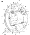
- FIGURE 1 illustrates a typical example of drum brake 9 which comprises a drum 95 coaxial with the wheel, mounted integral with the wheel, and whose skirt has an inner friction track 96.
- This skirt covers a mechanism mounted on a plate 90 coaxial with the axis A9 of the hub of the wheel, and which is integral with the half-gear carrying the hub.
- This mechanism comprises two segments 92, 93 in arcs mounted face to face around the axis of rotation A9 of the drum. On their outer surface, friction linings 923, 933 press on the drum track when they are spread outward.
- each segment is spaced at one end by an actuator 91, and its other end is tangentially supported by rotation on an abutment plate 94 secured to the plate 90, generally by riveting .
- the segments are pressurized against the drum track, any movement or force in rotation of the wheel prints a torque to the segments, they transmit to the plate by this stop plate.
- the two segments are actuated at their two ends on the same side, typically by the same hydraulic actuator 91 with double piston and fixed to the plate. This is the most classic mode, which is simple and reliable and regular operation.
- the parking brake function is to maintain a vehicle immobilized continuously for long periods of time. For a long time, as illustrated in FIGURE 1 it is known to perform this function within the same drum brake as for the service brake, using a lever 97 pulled by a cable 99 itself maintained by a ratchet mechanism. This lever pivots on the movable end of a segment 92, and away from the other segment by a reaction rod 98.
- the emergency brake function consists in slowing down a moving vehicle in an exceptional manner, for example in the event of failure of the service brake control circuit. Very often, this operation is performed by the same mechanism as the parking brake.
- this type of drum brake may have insufficient braking torque as a parking brake, and also as an emergency brake.
- a duo servo-type drum brake is sometimes used as a parking brake exclusively, for example by using as a drum the inside of the center bell of a disk that serves as a service brake, a combination called "Drum in hat” and described in the document EP 0 416 760 .
- the document FR 2,697,599 proposes to add a mechanical actuator near the stop plate.
- This actuator is supported on one side on one end of a first segment and the other on the end of an additional lever to separate them from one another.
- This lever slides freely along the other segment, and its opposite end presses a rod itself bearing on the movable end of the first segment.
- An object of the present invention is to provide a drum brake device offering flexibility of mounting the various existing elements to perform the functions of service brake, parking brake and emergency brake.
- Another object of the present invention is to provide a more efficient sealing of the various devices mentioned above.
- Yet another object of the present invention is to provide an economical device, and offering a reduced number of parts, ease and economy of manufacture and / or assembly and / or maintenance, while retaining all or part of the advantages. simplex mode, duplex and servo duo.
- the drum brake device for a motor vehicle causing a braking torque between a drum and a support plate in rotational movement relative to each other, by absorption of energy under the effect of a friction between, on the one hand, a friction track forming a cylinder of revolution and carried by an inner surface of said drum, and on the other hand friction linings carried by a first and a second segments disposed inside said cylinder and transmitting at least partly the braking torque between the segment and the support plate by at least one said anchoring member forming a stop for said segments relative to the support plate, said friction being able to be obtained by spacing at least one of said segments outwards under the effect of at least a first fixed actuator, thus ensuring a braking function in a first operating mode ioning.
- this device comprises a so-called intermediate element, which is movable relative to the plate, and which is arranged to maintain spaced from each other the two ends of said segments which are opposite one of the the other, say moving ends.
- the drum brake device according to the invention makes it possible to propose a device offering flexibility as to the mounting of the various existing and future elements in order to perform the functions of service brake, parking brake and emergency brake.
- the support plate has at least one through opening forming the positioning and fixing means for indifferently receiving the abutment element or the main housing of the at least one second actuator.
- the support plate has at least one through opening forming the positioning and fixing means for indifferently receiving the abutment element or the main housing of the at least one second actuator.
- the at least one opening has a substantially rectangular shape.
- the at least one opening may be substantially triangular or circular or may have the shape of a parallelogram or a parallelepiped.
- the at least one opening may be of variable dimensions depending on the element to be housed on the support plate. This has the advantage of facilitating the integration of the various existing elements and also the new elements to come.
- the main housing comprises a main bearing surface, preferably flat, arranged to bear against the support plate by complementary contact in at least two regions situated on two opposite sides around the at least one opening.
- the main bearing surface extends beyond the contour of the opening. In this way, the tightness with respect to the dust is ensured between the external environment and on the one hand the inside of the main housing and on the other hand the space inside the drum.
- the main housing of the second actuator comprises at least one or more fastening latches, and in particular two, each provided with at least one fastening orifice positioned to cooperate with an orifice of the plate for receiving clamping means of the second actuator against said support plate.
- the main housing comprises two fastening paws extending in the same plane as that of the main bearing surface and pressing against the support plate near the opening.
- a fixing orifice is formed at each fastening pawl.
- the fixing holes correspond with holes made in the support plate in order to make the second actuator secured to the plate preferably by riveting.
- Other embodiments are possible where several latches and several fixing holes are provided.
- the main housing is positioned in the opening by at least a first advance that protrudes from the main bearing surface.
- the first advance extends substantially in a transverse direction, preferably perpendicular to the plane of the main bearing surface from the main bearing surface and has a non-zero height so that the first advance can lean against the edge of the opening; the main bearing surface resting against the surface of the support plate.
- the second actuator is enclosed by assembling the main housing with a secondary housing extending through the opening the tray and which is assembled with the main housing by positioning in contact with at least one second projection protruding from a second bearing surface formed by a shoulder from the first advance of the main housing; the secondary housing bearing against the second bearing surface, the main housing and the secondary housing enclosing the second actuator.
- the second advance extends substantially in a transverse direction, preferably perpendicular to the plane of the main bearing surface from the second bearing surface after the first advance and has a non-zero height to that the second advance can rest against the inner surface of the secondary housing; the secondary housing resting against the second bearing surface from the first advance.
- the second bearing surface resulting from the first advance corresponds to the flat surface extending in a plane parallel to the plane of the main bearing surface.
- the second bearing surface has a non-zero width, preferably between 5 and 25 millimeters.
- the secondary housing is pinched between the support plate and the main housing which has at least one or more recesses on its periphery passing through the opening of the tray and extending against the surface of the tray on the housing side.
- main to each accommodate a bracket of the secondary housing; said securing tabs of the secondary housing being thus clamped between the main housing and the support plate.
- the two advances are traversed by at least one recess in which is embedded a bracket which protrudes from the secondary housing.
- the recess continues to advance into the main bearing surface of the main housing, where it receives the end of this bracket. This one is dimensioned to a sufficient thickness relative to the recess to be tightly clamped between the main housing and the tray when attached to each other.
- the support plate may have at least one recess around the periphery of the at least one opening to accommodate at least one bracket of the secondary housing.
- the secondary housing is fixed to the main housing by a single fastener, in particular a single screw.
- a geared motor housing enclosing an elongate geared motor element, driving the second actuator, is fixed to the secondary housing; the geared motor element being placed longitudinally in a direction substantially perpendicular to the axis of the support plate and the opposite side to the main housing relative to the plate.
- the geared motor housing extends substantially in a horizontal direction.
- the geared motor element is fixed by one of its ends and is cantilever with respect to the secondary housing.
- the main housing, the secondary housing and / or the geared motor housing are made of plastics.
- the main housing is made of metal, including a cast aluminum.
- the invention provides a vehicle or vehicle subassembly comprising a drum brake device according to the first aspect.
- the invention proposes a method of assembling a drum brake mechanism comprising a first and a second segment provided with outwardly directed friction linings. , which are capped by said drum and are mounted on a plate so as to be able to transmit to said plate a braking or holding torque by absorption of energy under the effect of friction with a cylindrical friction track carried by the inside said drum when so-called mobile ends of said segments are spaced outwards, under the effect of a first actuator, while their opposite ends called stop ends simultaneously bear on at least one anchoring means secured to the tray .
- the invention proposes a method, in particular according to the preceding aspect, wherein the plate and the second actuator are chosen to produce a drum brake device according to the first aspect.
- the method further comprises a subsequent step of positioning and fixing a gearmotor element via a geared motor housing, on the plateau side. opposite to the main housing, in a geared motor housing of the secondary housing of the second actuator.
- the invention proposes a method of assembling a vehicle or vehicle subassembly that comprises an assembly and / or a mounting a drum brake device as set forth herein.
- the invention improves the design flexibility of the brake and the vehicle that carries it, and their manufacture within production lines that can work on several different models or assembled with different options.
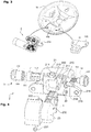
- the FIGURE 2 represents a "dual-mode" drum brake mechanism in an exemplary embodiment of the invention where more particularly the support plate 10 has an opening for accommodating the second actuator 2.
- This embodiment can be implemented with different types of actuators for the service brake mode, and different types of actuators for the parking or emergency brake actuator.
- This drum brake 1 causes a braking torque between the drum (not shown here) and the plate 10 in rotational movement relative to each other about an axis of rotation A1.
- the plate 10 is fixed in rotation on the chassis of the vehicle, generally by means of a suspended train or half-gear.
- the drum is secured to the wheel, and is fixed in translation and guided in rotation about the axis A1 by the hub and its bearings, not shown here.
- first actuator 11 here a hydraulic cylinder which can be fixed to the plate 10. From the rest position or from the braking position parking, this first actuator 11 thus brings the mechanism into the service braking position, and the return to the rest position is made for example by return springs interconnecting the two segments, as illustrated in FIG. FIGURE 2 .
- the drum brake is arranged to operate in simplex mode when actuated as a service brake:
- the first actuator 11 is a "cylinder of wheel” with two opposed pistons 111, which each actuate one of the segments 12, 13 by spacing from each other their two ends vis-à-vis 121, 131, c ' that is to say those located on the same side of the axis of rotation A1, here called “moving ends” and located at the top of the figure.
- each segment is supported on the plate 10 by an anchoring element secured to the plate, and thus forming a stop for this segment.
- the anchoring element thus serves as a braking torque transmission element between the segments and the plate 10.
- the anchoring element of the two segments is formed by a housing 21 of the second actuator 2, here called retractor.
- the second actuator 2 is fixed to the plate 10 by its housing 21.
- the anchoring element is made by a stop plate 94 generally riveted to the support plate 10.
- the spacer 2 comprises an actuating assembly which, in parking brake or emergency mode, presses the abutment ends 122, 132 of the segments 12, 13 to move them away from each other, and thus to put the segments bearing against the friction track of the drum.
- this second actuator 2 From the position of rest, or from the service braking position, this second actuator 2 thus brings the mechanism into the parking braking position, and the return to the rest position is achieved for example by the return springs already described for the service brake.
- the FIGURE 3 illustrates a support plate 10 advantageously to achieve several types of drum brake.
- the invention provides for choosing between several possibilities, possibly even when the tray is already attached to the vehicle or a subset of the vehicle.
- the support plate has several pre-cut concentric openings.
- the assembly then comprises an embossing operation of the support plate to obtain the desired opening as a function of the element to be integrated.
- the spacer 2 comprises two fastening pawls 218, which comprise fastening orifices 219, making it possible to place and fix the spacer 2 on the support plate 10.
- an inert stop plate 19 is fix in the opening 100 of the same plate an inert stop plate 19, previously manufactured for this purpose.
- Such an abutment plate also has fixing orifices 199 made in two fixing lugs of the abutment plate, making it possible in the same way to place and fix the abutment plate 19 on the support plate 10.
- the fixing orifices 199 or 219, respectively of the abutment plate tabs and of the spacer pawls, are in facing relation with holes made in the support plate.
- the face, of the abutment plate 19 and of the second actuator 2, or even another element, in contact with the support plate 10 carries identical assembly forms making it possible to selectively mount the various elements mentioned in the same opening 100.
- a drum brake 9 of a known type operating only in simplex for example with a parking brake lever 97 actuated by control cable 99 as that of the FIGURE 1 .
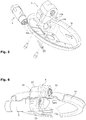
- the FIGURE 4 illustrates more particularly the form of assembly of the spacer 2 relative to the support plate 10 and to a secondary housing 23.
- the anchoring of the main housing 21 on the support plate 10 is provided by a main bearing surface 210 of the housing which is thus pressed into contact with the plate.
- the bearing surface 210 is substantially flat and bears against the support plate 10 around the opening 100 extending beyond the contour of the opening 100.
- this bearing surface 210 has a first projection 211 protruding from the bearing surface 210 and protruding through the opening 100 when placed in position on the plate 10.
- the outer surface of this first projection 211 presents a profile determined to cooperate with the periphery of the attachment opening 100 of the plate and perform the centering of the main housing 21 relative to this opening 100.
- the first advance 211 extends substantially in a transverse direction, preferably perpendicular to the plane of the main bearing surface 210 from the bearing surface main and has a non-zero height so that the first advance can rest against the edge of the opening 100.
- This first advance 211 ends with a shoulder forming a second bearing surface 212, on which bears the secondary housing 23 of the spacer 2.
- This second bearing surface 212 has a second projection 213, projecting relative to the second bearing surface 212 and protruding inside the housing of the secondary housing 23.
- the outer surface of this second projection 213 has a profile determined to cooperate with the periphery of the opening of the housing of the secondary housing 23 and achieve the centering of the secondary housing relative to the main housing 21.
- the second projection 213 extends substantially in a direction perpendicular (or at least 45 ° or even 60 °) to the plane of the surface of the housing. 210 main support from the second support surface 212.
- This second advance has a non-zero height to be able to lean against the opening of the housing t secondary housing 23.
- the two projections 211, 213 are traversed by a recess 214 which is embedded in a fastening tab 232 which protrudes from the secondary housing 23.
- the recess continues to advance in the main bearing surface 210 of the main housing 21, where it receives the bent end outwardly of the bracket 232. It is dimensioned to a sufficient thickness relative to the recess 214 to be tightly clamped between the main housing 21 and the tray 10 when attached to each other.
- the fastening tab 232 has a generally rectangular general shape in the plane of the main bearing surface 210.
- the fixing of the main housing 21 on the plate also carries the tightening of its assembly with the secondary housing.
- the prior assembly of the two housings 21, 23 requires only little or no means fastening, for example a simple latching or a single screw 231 as illustrated in FIG. FIGURE 4 .
- the spacer 2 is mounted and fixed on the support plate 10, sealingly engaged in the opening 100 of the inner side of the plate.
- the gearmotor element 5 is then assembled on the spacer 2 via the geared motor housing, on the part of its secondary housing 23 which protrudes from the plate on the opposite side to the segments, that is to say on the "back" side of the gearbox. tray.
- the second actuator 2 is fixed on the support plate 10.
- the geared motor element is then placed in a direction substantially perpendicular to the axis A1 of the support plate 10 and more precisely in a direction parallel to the plane of the surface of the main support 210.
- the geared motor element 5 is cantilever with respect to the secondary housing 23.
- the plate 10 and the stop plate 19 represent an extremely low cost and low or no constraints on the design and manufacture.
Landscapes
- Engineering & Computer Science (AREA)
- General Engineering & Computer Science (AREA)
- Mechanical Engineering (AREA)
- Transportation (AREA)
- Physics & Mathematics (AREA)
- Fluid Mechanics (AREA)
- Braking Arrangements (AREA)
- Braking Systems And Boosters (AREA)
Priority Applications (1)
| Application Number | Priority Date | Filing Date | Title |
|---|---|---|---|
| PL14827739T PL3089897T3 (pl) | 2013-12-30 | 2014-12-16 | Urządzenie hamulca bębnowego z możliwością przystosowania tak, aby zawierało hamulec postojowy klasyczny lub działający w trybie duo serwo |
Applications Claiming Priority (2)
| Application Number | Priority Date | Filing Date | Title |
|---|---|---|---|
| FR1363701A FR3016009B1 (fr) | 2013-12-30 | 2013-12-30 | Dispositif de frein a tambour adaptable pour inclure un frein de stationnement traditionnel ou fonctionnant en mode duo servo |
| PCT/EP2014/078023 WO2015101484A2 (fr) | 2013-12-30 | 2014-12-16 | Dispositif de frein a tambour adaptable pour inclure un frein de stationnement traditionnel ou fonctionnant en mode duo servo |
Publications (2)
| Publication Number | Publication Date |
|---|---|
| EP3089897A2 EP3089897A2 (fr) | 2016-11-09 |
| EP3089897B1 true EP3089897B1 (fr) | 2018-02-07 |
Family
ID=50483074
Family Applications (1)
| Application Number | Title | Priority Date | Filing Date |
|---|---|---|---|
| EP14827739.5A Active EP3089897B1 (fr) | 2013-12-30 | 2014-12-16 | Dispositif de frein a tambour adaptable pour inclure un frein de stationnement traditionnel ou fonctionnant en mode duo servo |
Country Status (8)
| Country | Link |
|---|---|
| EP (1) | EP3089897B1 (enExample) |
| JP (1) | JP6602307B2 (enExample) |
| CN (1) | CN106104057B (enExample) |
| ES (1) | ES2666906T3 (enExample) |
| FR (1) | FR3016009B1 (enExample) |
| PL (1) | PL3089897T3 (enExample) |
| PT (1) | PT3089897T (enExample) |
| WO (1) | WO2015101484A2 (enExample) |
Cited By (3)
| Publication number | Priority date | Publication date | Assignee | Title |
|---|---|---|---|---|
| DE102020213917A1 (de) | 2020-11-05 | 2022-05-05 | Continental Teves Ag & Co. Ohg | Trommelbremse |
| DE112020001882B4 (de) | 2019-04-12 | 2025-03-27 | Hl Mando Corporation | Elektronische feststellbremse |
| FR3157488A1 (fr) * | 2023-12-22 | 2025-06-27 | Hitachi Astemo France | Frein a tambour duo servo comprenant un support de premier actionneur servant de point fixe |
Families Citing this family (4)
| Publication number | Priority date | Publication date | Assignee | Title |
|---|---|---|---|---|
| FR3067426B1 (fr) * | 2017-06-12 | 2022-09-09 | Foundation Brakes France | Frein a tambour comportant un dispositif d'entrainement electrique d'un actionneur de frein de parking a montage ameliore |
| JP6972866B2 (ja) | 2017-09-29 | 2021-11-24 | 株式会社アドヴィックス | 車両用ブレーキ |
| KR102822450B1 (ko) * | 2020-06-23 | 2025-06-20 | 현대모비스 주식회사 | 드럼 브레이크 장치 |
| KR102822451B1 (ko) * | 2020-06-23 | 2025-06-20 | 현대모비스 주식회사 | 드럼 브레이크 장치 |
Family Cites Families (10)
| Publication number | Priority date | Publication date | Assignee | Title |
|---|---|---|---|---|
| US4553647A (en) * | 1984-04-05 | 1985-11-19 | Allied Corporation | Wheel cylinder and torque plate construction |
| DE69009360T2 (de) | 1989-08-29 | 1994-09-15 | Kelsey Hayes Co | Aufbau einer Bremse. |
| US5269396A (en) * | 1991-02-28 | 1993-12-14 | Jones Brake Technologies, Inc. | Brake assembly backing means |
| FR2697599B1 (fr) | 1992-10-30 | 1994-12-30 | Bendix Europ Services Tech | Frein à tambour à actionnement mécanique. |
| JP3283028B2 (ja) * | 2000-02-24 | 2002-05-20 | 豊生ブレーキ工業株式会社 | ブレーキケーブル接続装置 |
| US6405838B1 (en) * | 2000-08-08 | 2002-06-18 | Delphi Technologies, Inc. | Electric parking brake for drum brakes |
| DE112006002895B4 (de) * | 2005-10-31 | 2021-12-16 | ZF Active Safety US lnc. | Elektrische Betätigungseinheit für eine Fahrzeugbremsanordnung |
| CN201794967U (zh) * | 2009-11-26 | 2011-04-13 | 甘肃洮河拖拉机制造有限公司 | 双液压油缸同步制动器 |
| KR20130037875A (ko) * | 2011-10-07 | 2013-04-17 | 주식회사 만도 | 전자식 파킹 브레이크 |
| JP5844630B2 (ja) * | 2011-12-14 | 2016-01-20 | 曙ブレーキ工業株式会社 | ドラムブレーキ式電動駐車ブレーキ装置 |
-
2013
- 2013-12-30 FR FR1363701A patent/FR3016009B1/fr not_active Expired - Fee Related
-
2014
- 2014-12-16 JP JP2016544619A patent/JP6602307B2/ja active Active
- 2014-12-16 PT PT148277395T patent/PT3089897T/pt unknown
- 2014-12-16 WO PCT/EP2014/078023 patent/WO2015101484A2/fr not_active Ceased
- 2014-12-16 ES ES14827739.5T patent/ES2666906T3/es active Active
- 2014-12-16 CN CN201480075026.0A patent/CN106104057B/zh active Active
- 2014-12-16 EP EP14827739.5A patent/EP3089897B1/fr active Active
- 2014-12-16 PL PL14827739T patent/PL3089897T3/pl unknown
Cited By (5)
| Publication number | Priority date | Publication date | Assignee | Title |
|---|---|---|---|---|
| DE112020001882B4 (de) | 2019-04-12 | 2025-03-27 | Hl Mando Corporation | Elektronische feststellbremse |
| US12467510B2 (en) | 2019-04-12 | 2025-11-11 | Hl Mando Corporation | Electronic parking brake |
| DE102020213917A1 (de) | 2020-11-05 | 2022-05-05 | Continental Teves Ag & Co. Ohg | Trommelbremse |
| DE102020213917B4 (de) | 2020-11-05 | 2026-04-16 | Aumovio Germany Gmbh | Trommelbremse |
| FR3157488A1 (fr) * | 2023-12-22 | 2025-06-27 | Hitachi Astemo France | Frein a tambour duo servo comprenant un support de premier actionneur servant de point fixe |
Also Published As
| Publication number | Publication date |
|---|---|
| JP2017502231A (ja) | 2017-01-19 |
| FR3016009B1 (fr) | 2016-02-12 |
| WO2015101484A2 (fr) | 2015-07-09 |
| WO2015101484A3 (fr) | 2015-11-26 |
| PT3089897T (pt) | 2018-05-16 |
| ES2666906T3 (es) | 2018-05-08 |
| EP3089897A2 (fr) | 2016-11-09 |
| CN106104057B (zh) | 2018-09-14 |
| CN106104057A (zh) | 2016-11-09 |
| PL3089897T3 (pl) | 2018-07-31 |
| JP6602307B2 (ja) | 2019-11-06 |
| FR3016009A1 (fr) | 2015-07-03 |
Similar Documents
| Publication | Publication Date | Title |
|---|---|---|
| EP3089897B1 (fr) | Dispositif de frein a tambour adaptable pour inclure un frein de stationnement traditionnel ou fonctionnant en mode duo servo | |
| EP3089899B1 (fr) | Actionneur entraine par pignon a glissiere axiale, et frein a tambour et dispositif de freinage ainsi equipes | |
| EP2992236B2 (fr) | Frein à disque à étrier fixe et à patins de frein stabilisés, et procédés associés d'assemblage et de remplacement d'un patin | |
| EP3089898B1 (fr) | Dispositif de frein a tambour incluant un frein de stationnement fonctionnant en mode duo servo, vehicule et procedes d'assemblage associes | |
| EP3089901B1 (fr) | Motoreducteur a train epicycloidal, frein a tambour, frein a disque et dispositif de freinage ainsi equipes | |
| EP3089896B1 (fr) | Actionneur avec sous-ensemble de transmission a engrenage, et frein a tambour et dispositif de freinage ainsi equipes | |
| EP2649341B1 (fr) | Frein à disque à verrou de blocage de la cartouche de conversion par un verrou | |
| EP0203841B1 (fr) | Ressort pour frein à disque | |
| EP0028955B1 (fr) | Frein à disque à étrier coulissant | |
| EP1800018B1 (fr) | Element de friction et frein a disque | |
| EP3175136B1 (fr) | Actionneur de freinage pour véhicule | |
| FR3016013A1 (fr) | Actionneur de frein a tambour avec motorisation par emboitement a jeu angulaire | |
| EP3089900B1 (fr) | Motoreducteur avec moteur electrique adaptable pour actionneur de frein a tambour | |
| EP2475557B1 (fr) | Piston d'actionneur de servofrein et servofrein equipe d'un tel piston. | |
| EP0694134B1 (fr) | Ensemble d'un element de friction equipe d'un ressort pour frein a disque | |
| FR2734616A1 (fr) | Embrayage a friction a disques multiples comportant une butee axiale | |
| WO2000057076A1 (fr) | Dispositif de montage d'un diaphragme sur un couvercle d'embrayage | |
| EP0360650A1 (fr) | Butée de débrayage, notamment pour véhicules automobiles | |
| FR3110653A1 (fr) | Dispositif de maintien pour frein à tambour pour véhicule routier, notamment automobile | |
| WO2020234390A1 (fr) | Frein à tambour a couple residuel reduit | |
| FR3067426A1 (fr) | Frein a tambour comportant un dispositif d'entrainement electrique d'un actionneur de frein de parking a montage ameliore | |
| FR3067427A1 (fr) | Element de montage sur un plateau de frein a tambour d'un dispositif d'entrainement, de preference electrique et un frein a tambour comportant au moins un tel element de montage | |
| FR3062442A1 (fr) | Mecanisme d'embrayage, notamment pour vehicule automobile | |
| FR3097021A1 (fr) | Reducteur et motoreducteur pour frein a débrayage intégré | |
| EP4559767A1 (fr) | Frein a disque, notamment pour vehicule automobile |
Legal Events
| Date | Code | Title | Description |
|---|---|---|---|
| PUAI | Public reference made under article 153(3) epc to a published international application that has entered the european phase |
Free format text: ORIGINAL CODE: 0009012 |
|
| 17P | Request for examination filed |
Effective date: 20160727 |
|
| AK | Designated contracting states |
Kind code of ref document: A2 Designated state(s): AL AT BE BG CH CY CZ DE DK EE ES FI FR GB GR HR HU IE IS IT LI LT LU LV MC MK MT NL NO PL PT RO RS SE SI SK SM TR |
|
| AX | Request for extension of the european patent |
Extension state: BA ME |
|
| RIN1 | Information on inventor provided before grant (corrected) |
Inventor name: DUPAS, CHRISTOPHE Inventor name: GUIGNON, CEDRIC Inventor name: MOLINARO, ALBERTO Inventor name: LUU, GERARD Inventor name: PASQUET, THIERRY |
|
| DAX | Request for extension of the european patent (deleted) | ||
| GRAP | Despatch of communication of intention to grant a patent |
Free format text: ORIGINAL CODE: EPIDOSNIGR1 |
|
| STAA | Information on the status of an ep patent application or granted ep patent |
Free format text: STATUS: GRANT OF PATENT IS INTENDED |
|
| INTG | Intention to grant announced |
Effective date: 20170511 |
|
| RAP1 | Party data changed (applicant data changed or rights of an application transferred) |
Owner name: CHASSIS BRAKES INTERNATIONAL B.V. |
|
| GRAS | Grant fee paid |
Free format text: ORIGINAL CODE: EPIDOSNIGR3 |
|
| GRAJ | Information related to disapproval of communication of intention to grant by the applicant or resumption of examination proceedings by the epo deleted |
Free format text: ORIGINAL CODE: EPIDOSDIGR1 |
|
| GRAL | Information related to payment of fee for publishing/printing deleted |
Free format text: ORIGINAL CODE: EPIDOSDIGR3 |
|
| STAA | Information on the status of an ep patent application or granted ep patent |
Free format text: STATUS: REQUEST FOR EXAMINATION WAS MADE |
|
| INTC | Intention to grant announced (deleted) | ||
| GRAP | Despatch of communication of intention to grant a patent |
Free format text: ORIGINAL CODE: EPIDOSNIGR1 |
|
| STAA | Information on the status of an ep patent application or granted ep patent |
Free format text: STATUS: GRANT OF PATENT IS INTENDED |
|
| INTG | Intention to grant announced |
Effective date: 20171024 |
|
| GRAA | (expected) grant |
Free format text: ORIGINAL CODE: 0009210 |
|
| STAA | Information on the status of an ep patent application or granted ep patent |
Free format text: STATUS: THE PATENT HAS BEEN GRANTED |
|
| AK | Designated contracting states |
Kind code of ref document: B1 Designated state(s): AL AT BE BG CH CY CZ DE DK EE ES FI FR GB GR HR HU IE IS IT LI LT LU LV MC MK MT NL NO PL PT RO RS SE SI SK SM TR |
|
| REG | Reference to a national code |
Ref country code: GB Ref legal event code: FG4D Free format text: NOT ENGLISH |
|
| REG | Reference to a national code |
Ref country code: AT Ref legal event code: REF Ref document number: 968652 Country of ref document: AT Kind code of ref document: T Effective date: 20180215 Ref country code: CH Ref legal event code: EP |
|
| REG | Reference to a national code |
Ref country code: IE Ref legal event code: FG4D Free format text: LANGUAGE OF EP DOCUMENT: FRENCH |
|
| REG | Reference to a national code |
Ref country code: DE Ref legal event code: R096 Ref document number: 602014020816 Country of ref document: DE |
|
| REG | Reference to a national code |
Ref country code: ES Ref legal event code: FG2A Ref document number: 2666906 Country of ref document: ES Kind code of ref document: T3 Effective date: 20180508 |
|
| REG | Reference to a national code |
Ref country code: PT Ref legal event code: SC4A Ref document number: 3089897 Country of ref document: PT Date of ref document: 20180516 Kind code of ref document: T Free format text: AVAILABILITY OF NATIONAL TRANSLATION Effective date: 20180426 |
|
| REG | Reference to a national code |
Ref country code: NL Ref legal event code: MP Effective date: 20180207 |
|
| REG | Reference to a national code |
Ref country code: AT Ref legal event code: MK05 Ref document number: 968652 Country of ref document: AT Kind code of ref document: T Effective date: 20180207 |
|
| PG25 | Lapsed in a contracting state [announced via postgrant information from national office to epo] |
Ref country code: CY Free format text: LAPSE BECAUSE OF FAILURE TO SUBMIT A TRANSLATION OF THE DESCRIPTION OR TO PAY THE FEE WITHIN THE PRESCRIBED TIME-LIMIT Effective date: 20180207 Ref country code: LT Free format text: LAPSE BECAUSE OF FAILURE TO SUBMIT A TRANSLATION OF THE DESCRIPTION OR TO PAY THE FEE WITHIN THE PRESCRIBED TIME-LIMIT Effective date: 20180207 Ref country code: HR Free format text: LAPSE BECAUSE OF FAILURE TO SUBMIT A TRANSLATION OF THE DESCRIPTION OR TO PAY THE FEE WITHIN THE PRESCRIBED TIME-LIMIT Effective date: 20180207 Ref country code: NL Free format text: LAPSE BECAUSE OF FAILURE TO SUBMIT A TRANSLATION OF THE DESCRIPTION OR TO PAY THE FEE WITHIN THE PRESCRIBED TIME-LIMIT Effective date: 20180207 Ref country code: NO Free format text: LAPSE BECAUSE OF FAILURE TO SUBMIT A TRANSLATION OF THE DESCRIPTION OR TO PAY THE FEE WITHIN THE PRESCRIBED TIME-LIMIT Effective date: 20180507 Ref country code: FI Free format text: LAPSE BECAUSE OF FAILURE TO SUBMIT A TRANSLATION OF THE DESCRIPTION OR TO PAY THE FEE WITHIN THE PRESCRIBED TIME-LIMIT Effective date: 20180207 |
|
| PG25 | Lapsed in a contracting state [announced via postgrant information from national office to epo] |
Ref country code: IS Free format text: LAPSE BECAUSE OF FAILURE TO SUBMIT A TRANSLATION OF THE DESCRIPTION OR TO PAY THE FEE WITHIN THE PRESCRIBED TIME-LIMIT Effective date: 20180607 Ref country code: GR Free format text: LAPSE BECAUSE OF FAILURE TO SUBMIT A TRANSLATION OF THE DESCRIPTION OR TO PAY THE FEE WITHIN THE PRESCRIBED TIME-LIMIT Effective date: 20180508 Ref country code: AT Free format text: LAPSE BECAUSE OF FAILURE TO SUBMIT A TRANSLATION OF THE DESCRIPTION OR TO PAY THE FEE WITHIN THE PRESCRIBED TIME-LIMIT Effective date: 20180207 Ref country code: SE Free format text: LAPSE BECAUSE OF FAILURE TO SUBMIT A TRANSLATION OF THE DESCRIPTION OR TO PAY THE FEE WITHIN THE PRESCRIBED TIME-LIMIT Effective date: 20180207 Ref country code: LV Free format text: LAPSE BECAUSE OF FAILURE TO SUBMIT A TRANSLATION OF THE DESCRIPTION OR TO PAY THE FEE WITHIN THE PRESCRIBED TIME-LIMIT Effective date: 20180207 Ref country code: RS Free format text: LAPSE BECAUSE OF FAILURE TO SUBMIT A TRANSLATION OF THE DESCRIPTION OR TO PAY THE FEE WITHIN THE PRESCRIBED TIME-LIMIT Effective date: 20180207 Ref country code: BG Free format text: LAPSE BECAUSE OF FAILURE TO SUBMIT A TRANSLATION OF THE DESCRIPTION OR TO PAY THE FEE WITHIN THE PRESCRIBED TIME-LIMIT Effective date: 20180507 |
|
| PG25 | Lapsed in a contracting state [announced via postgrant information from national office to epo] |
Ref country code: MT Free format text: LAPSE BECAUSE OF FAILURE TO SUBMIT A TRANSLATION OF THE DESCRIPTION OR TO PAY THE FEE WITHIN THE PRESCRIBED TIME-LIMIT Effective date: 20180207 |
|
| PG25 | Lapsed in a contracting state [announced via postgrant information from national office to epo] |
Ref country code: AL Free format text: LAPSE BECAUSE OF FAILURE TO SUBMIT A TRANSLATION OF THE DESCRIPTION OR TO PAY THE FEE WITHIN THE PRESCRIBED TIME-LIMIT Effective date: 20180207 Ref country code: EE Free format text: LAPSE BECAUSE OF FAILURE TO SUBMIT A TRANSLATION OF THE DESCRIPTION OR TO PAY THE FEE WITHIN THE PRESCRIBED TIME-LIMIT Effective date: 20180207 Ref country code: RO Free format text: LAPSE BECAUSE OF FAILURE TO SUBMIT A TRANSLATION OF THE DESCRIPTION OR TO PAY THE FEE WITHIN THE PRESCRIBED TIME-LIMIT Effective date: 20180207 |
|
| REG | Reference to a national code |
Ref country code: DE Ref legal event code: R097 Ref document number: 602014020816 Country of ref document: DE |
|
| PG25 | Lapsed in a contracting state [announced via postgrant information from national office to epo] |
Ref country code: DK Free format text: LAPSE BECAUSE OF FAILURE TO SUBMIT A TRANSLATION OF THE DESCRIPTION OR TO PAY THE FEE WITHIN THE PRESCRIBED TIME-LIMIT Effective date: 20180207 Ref country code: CZ Free format text: LAPSE BECAUSE OF FAILURE TO SUBMIT A TRANSLATION OF THE DESCRIPTION OR TO PAY THE FEE WITHIN THE PRESCRIBED TIME-LIMIT Effective date: 20180207 Ref country code: SK Free format text: LAPSE BECAUSE OF FAILURE TO SUBMIT A TRANSLATION OF THE DESCRIPTION OR TO PAY THE FEE WITHIN THE PRESCRIBED TIME-LIMIT Effective date: 20180207 Ref country code: SM Free format text: LAPSE BECAUSE OF FAILURE TO SUBMIT A TRANSLATION OF THE DESCRIPTION OR TO PAY THE FEE WITHIN THE PRESCRIBED TIME-LIMIT Effective date: 20180207 |
|
| PLBE | No opposition filed within time limit |
Free format text: ORIGINAL CODE: 0009261 |
|
| STAA | Information on the status of an ep patent application or granted ep patent |
Free format text: STATUS: NO OPPOSITION FILED WITHIN TIME LIMIT |
|
| 26N | No opposition filed |
Effective date: 20181108 |
|
| PG25 | Lapsed in a contracting state [announced via postgrant information from national office to epo] |
Ref country code: SI Free format text: LAPSE BECAUSE OF FAILURE TO SUBMIT A TRANSLATION OF THE DESCRIPTION OR TO PAY THE FEE WITHIN THE PRESCRIBED TIME-LIMIT Effective date: 20180207 |
|
| REG | Reference to a national code |
Ref country code: CH Ref legal event code: PL |
|
| PG25 | Lapsed in a contracting state [announced via postgrant information from national office to epo] |
Ref country code: MC Free format text: LAPSE BECAUSE OF FAILURE TO SUBMIT A TRANSLATION OF THE DESCRIPTION OR TO PAY THE FEE WITHIN THE PRESCRIBED TIME-LIMIT Effective date: 20180207 Ref country code: LU Free format text: LAPSE BECAUSE OF NON-PAYMENT OF DUE FEES Effective date: 20181216 |
|
| REG | Reference to a national code |
Ref country code: IE Ref legal event code: MM4A |
|
| REG | Reference to a national code |
Ref country code: BE Ref legal event code: MM Effective date: 20181231 |
|
| PG25 | Lapsed in a contracting state [announced via postgrant information from national office to epo] |
Ref country code: IE Free format text: LAPSE BECAUSE OF NON-PAYMENT OF DUE FEES Effective date: 20181216 |
|
| PG25 | Lapsed in a contracting state [announced via postgrant information from national office to epo] |
Ref country code: BE Free format text: LAPSE BECAUSE OF NON-PAYMENT OF DUE FEES Effective date: 20181231 |
|
| PG25 | Lapsed in a contracting state [announced via postgrant information from national office to epo] |
Ref country code: LI Free format text: LAPSE BECAUSE OF NON-PAYMENT OF DUE FEES Effective date: 20181231 Ref country code: CH Free format text: LAPSE BECAUSE OF NON-PAYMENT OF DUE FEES Effective date: 20181231 |
|
| PG25 | Lapsed in a contracting state [announced via postgrant information from national office to epo] |
Ref country code: HU Free format text: LAPSE BECAUSE OF FAILURE TO SUBMIT A TRANSLATION OF THE DESCRIPTION OR TO PAY THE FEE WITHIN THE PRESCRIBED TIME-LIMIT; INVALID AB INITIO Effective date: 20141216 Ref country code: MK Free format text: LAPSE BECAUSE OF NON-PAYMENT OF DUE FEES Effective date: 20180207 |
|
| PGFP | Annual fee paid to national office [announced via postgrant information from national office to epo] |
Ref country code: TR Payment date: 20221129 Year of fee payment: 9 Ref country code: PT Payment date: 20221123 Year of fee payment: 9 Ref country code: IT Payment date: 20221122 Year of fee payment: 9 Ref country code: GB Payment date: 20221116 Year of fee payment: 9 |
|
| PGFP | Annual fee paid to national office [announced via postgrant information from national office to epo] |
Ref country code: PL Payment date: 20221122 Year of fee payment: 9 |
|
| PGFP | Annual fee paid to national office [announced via postgrant information from national office to epo] |
Ref country code: ES Payment date: 20230102 Year of fee payment: 9 |
|
| PG25 | Lapsed in a contracting state [announced via postgrant information from national office to epo] |
Ref country code: PT Free format text: LAPSE BECAUSE OF NON-PAYMENT OF DUE FEES Effective date: 20240617 |
|
| GBPC | Gb: european patent ceased through non-payment of renewal fee |
Effective date: 20231216 |
|
| PG25 | Lapsed in a contracting state [announced via postgrant information from national office to epo] |
Ref country code: PT Free format text: LAPSE BECAUSE OF NON-PAYMENT OF DUE FEES Effective date: 20240617 |
|
| PG25 | Lapsed in a contracting state [announced via postgrant information from national office to epo] |
Ref country code: GB Free format text: LAPSE BECAUSE OF NON-PAYMENT OF DUE FEES Effective date: 20231216 |
|
| PG25 | Lapsed in a contracting state [announced via postgrant information from national office to epo] |
Ref country code: GB Free format text: LAPSE BECAUSE OF NON-PAYMENT OF DUE FEES Effective date: 20231216 |
|
| REG | Reference to a national code |
Ref country code: ES Ref legal event code: FD2A Effective date: 20250203 |
|
| PG25 | Lapsed in a contracting state [announced via postgrant information from national office to epo] |
Ref country code: ES Free format text: LAPSE BECAUSE OF NON-PAYMENT OF DUE FEES Effective date: 20231217 |
|
| PG25 | Lapsed in a contracting state [announced via postgrant information from national office to epo] |
Ref country code: PL Free format text: LAPSE BECAUSE OF NON-PAYMENT OF DUE FEES Effective date: 20231216 |
|
| PG25 | Lapsed in a contracting state [announced via postgrant information from national office to epo] |
Ref country code: IT Free format text: LAPSE BECAUSE OF NON-PAYMENT OF DUE FEES Effective date: 20231216 |
|
| PGFP | Annual fee paid to national office [announced via postgrant information from national office to epo] |
Ref country code: DE Payment date: 20251126 Year of fee payment: 12 |
|
| PGFP | Annual fee paid to national office [announced via postgrant information from national office to epo] |
Ref country code: FR Payment date: 20251120 Year of fee payment: 12 |