EP3089869B1 - Optischer film mit verbessertem licht-zu-solareintragswärme-verhältnis - Google Patents
Optischer film mit verbessertem licht-zu-solareintragswärme-verhältnis Download PDFInfo
- Publication number
- EP3089869B1 EP3089869B1 EP14877504.2A EP14877504A EP3089869B1 EP 3089869 B1 EP3089869 B1 EP 3089869B1 EP 14877504 A EP14877504 A EP 14877504A EP 3089869 B1 EP3089869 B1 EP 3089869B1
- Authority
- EP
- European Patent Office
- Prior art keywords
- layer
- composite
- metal
- metal oxide
- oxide
- Prior art date
- Legal status (The legal status is an assumption and is not a legal conclusion. Google has not performed a legal analysis and makes no representation as to the accuracy of the status listed.)
- Active
Links
- 239000012788 optical film Substances 0.000 title description 4
- 230000001747 exhibiting effect Effects 0.000 title 1
- 239000002131 composite material Substances 0.000 claims description 153
- 229910044991 metal oxide Inorganic materials 0.000 claims description 119
- 150000004706 metal oxides Chemical class 0.000 claims description 119
- 229910052751 metal Inorganic materials 0.000 claims description 72
- 239000002184 metal Substances 0.000 claims description 72
- BQCADISMDOOEFD-UHFFFAOYSA-N Silver Chemical compound [Ag] BQCADISMDOOEFD-UHFFFAOYSA-N 0.000 claims description 66
- 229910052709 silver Inorganic materials 0.000 claims description 66
- 239000004332 silver Substances 0.000 claims description 66
- GWEVSGVZZGPLCZ-UHFFFAOYSA-N Titan oxide Chemical compound O=[Ti]=O GWEVSGVZZGPLCZ-UHFFFAOYSA-N 0.000 claims description 55
- OGIDPMRJRNCKJF-UHFFFAOYSA-N titanium oxide Inorganic materials [Ti]=O OGIDPMRJRNCKJF-UHFFFAOYSA-N 0.000 claims description 46
- 229910000484 niobium oxide Inorganic materials 0.000 claims description 41
- URLJKFSTXLNXLG-UHFFFAOYSA-N niobium(5+);oxygen(2-) Chemical compound [O-2].[O-2].[O-2].[O-2].[O-2].[Nb+5].[Nb+5] URLJKFSTXLNXLG-UHFFFAOYSA-N 0.000 claims description 41
- 239000000758 substrate Substances 0.000 claims description 39
- XLOMVQKBTHCTTD-UHFFFAOYSA-N Zinc monoxide Chemical compound [Zn]=O XLOMVQKBTHCTTD-UHFFFAOYSA-N 0.000 claims description 36
- 230000000007 visual effect Effects 0.000 claims description 22
- 239000011787 zinc oxide Substances 0.000 claims description 18
- 238000002834 transmittance Methods 0.000 claims description 16
- 229920000642 polymer Polymers 0.000 claims 1
- 239000010410 layer Substances 0.000 description 308
- 239000010408 film Substances 0.000 description 53
- 238000000151 deposition Methods 0.000 description 24
- 230000008021 deposition Effects 0.000 description 24
- 239000000463 material Substances 0.000 description 16
- 239000013078 crystal Substances 0.000 description 15
- 238000000034 method Methods 0.000 description 14
- 230000003287 optical effect Effects 0.000 description 13
- 239000010931 gold Substances 0.000 description 12
- PCHJSUWPFVWCPO-UHFFFAOYSA-N gold Chemical compound [Au] PCHJSUWPFVWCPO-UHFFFAOYSA-N 0.000 description 9
- 229910052737 gold Inorganic materials 0.000 description 9
- 238000004519 manufacturing process Methods 0.000 description 7
- -1 such as Polymers 0.000 description 6
- 230000002195 synergetic effect Effects 0.000 description 6
- 239000000919 ceramic Substances 0.000 description 5
- 230000005855 radiation Effects 0.000 description 5
- 238000004544 sputter deposition Methods 0.000 description 5
- KDLHZDBZIXYQEI-UHFFFAOYSA-N Palladium Chemical compound [Pd] KDLHZDBZIXYQEI-UHFFFAOYSA-N 0.000 description 4
- 229910003087 TiOx Inorganic materials 0.000 description 4
- 238000001755 magnetron sputter deposition Methods 0.000 description 4
- JKQOBWVOAYFWKG-UHFFFAOYSA-N molybdenum trioxide Chemical compound O=[Mo](=O)=O JKQOBWVOAYFWKG-UHFFFAOYSA-N 0.000 description 4
- BASFCYQUMIYNBI-UHFFFAOYSA-N platinum Chemical compound [Pt] BASFCYQUMIYNBI-UHFFFAOYSA-N 0.000 description 4
- 229920000139 polyethylene terephthalate Polymers 0.000 description 4
- 239000005020 polyethylene terephthalate Substances 0.000 description 4
- 238000002310 reflectometry Methods 0.000 description 4
- HLLICFJUWSZHRJ-UHFFFAOYSA-N tioxidazole Chemical compound CCCOC1=CC=C2N=C(NC(=O)OC)SC2=C1 HLLICFJUWSZHRJ-UHFFFAOYSA-N 0.000 description 4
- 230000000694 effects Effects 0.000 description 3
- 230000008020 evaporation Effects 0.000 description 3
- 238000001704 evaporation Methods 0.000 description 3
- 239000004408 titanium dioxide Substances 0.000 description 3
- 238000001771 vacuum deposition Methods 0.000 description 3
- RYGMFSIKBFXOCR-UHFFFAOYSA-N Copper Chemical compound [Cu] RYGMFSIKBFXOCR-UHFFFAOYSA-N 0.000 description 2
- HCHKCACWOHOZIP-UHFFFAOYSA-N Zinc Chemical compound [Zn] HCHKCACWOHOZIP-UHFFFAOYSA-N 0.000 description 2
- 229910052782 aluminium Inorganic materials 0.000 description 2
- XAGFODPZIPBFFR-UHFFFAOYSA-N aluminium Chemical compound [Al] XAGFODPZIPBFFR-UHFFFAOYSA-N 0.000 description 2
- 229910052802 copper Inorganic materials 0.000 description 2
- 239000010949 copper Substances 0.000 description 2
- 239000011521 glass Substances 0.000 description 2
- 238000001534 heteroepitaxy Methods 0.000 description 2
- 229910052738 indium Inorganic materials 0.000 description 2
- APFVFJFRJDLVQX-UHFFFAOYSA-N indium atom Chemical compound [In] APFVFJFRJDLVQX-UHFFFAOYSA-N 0.000 description 2
- 238000005259 measurement Methods 0.000 description 2
- 229910001092 metal group alloy Inorganic materials 0.000 description 2
- ZKATWMILCYLAPD-UHFFFAOYSA-N niobium pentoxide Chemical compound O=[Nb](=O)O[Nb](=O)=O ZKATWMILCYLAPD-UHFFFAOYSA-N 0.000 description 2
- TWNQGVIAIRXVLR-UHFFFAOYSA-N oxo(oxoalumanyloxy)alumane Chemical compound O=[Al]O[Al]=O TWNQGVIAIRXVLR-UHFFFAOYSA-N 0.000 description 2
- 229910052763 palladium Inorganic materials 0.000 description 2
- 229910052697 platinum Inorganic materials 0.000 description 2
- 238000001429 visible spectrum Methods 0.000 description 2
- 229910052725 zinc Inorganic materials 0.000 description 2
- 239000011701 zinc Substances 0.000 description 2
- 229910052984 zinc sulfide Inorganic materials 0.000 description 2
- RTAQQCXQSZGOHL-UHFFFAOYSA-N Titanium Chemical compound [Ti] RTAQQCXQSZGOHL-UHFFFAOYSA-N 0.000 description 1
- 238000005299 abrasion Methods 0.000 description 1
- 239000012790 adhesive layer Substances 0.000 description 1
- 238000000231 atomic layer deposition Methods 0.000 description 1
- QVGXLLKOCUKJST-UHFFFAOYSA-N atomic oxygen Chemical compound [O] QVGXLLKOCUKJST-UHFFFAOYSA-N 0.000 description 1
- 230000015572 biosynthetic process Effects 0.000 description 1
- 230000000903 blocking effect Effects 0.000 description 1
- 229920002678 cellulose Polymers 0.000 description 1
- 239000001913 cellulose Substances 0.000 description 1
- RKTYLMNFRDHKIL-UHFFFAOYSA-N copper;5,10,15,20-tetraphenylporphyrin-22,24-diide Chemical group [Cu+2].C1=CC(C(=C2C=CC([N-]2)=C(C=2C=CC=CC=2)C=2C=CC(N=2)=C(C=2C=CC=CC=2)C2=CC=C3[N-]2)C=2C=CC=CC=2)=NC1=C3C1=CC=CC=C1 RKTYLMNFRDHKIL-UHFFFAOYSA-N 0.000 description 1
- 238000002425 crystallisation Methods 0.000 description 1
- 230000008025 crystallization Effects 0.000 description 1
- 229920002313 fluoropolymer Polymers 0.000 description 1
- 239000004811 fluoropolymer Substances 0.000 description 1
- 238000010438 heat treatment Methods 0.000 description 1
- 239000012535 impurity Substances 0.000 description 1
- 238000002329 infrared spectrum Methods 0.000 description 1
- 239000010955 niobium Substances 0.000 description 1
- 229910052760 oxygen Inorganic materials 0.000 description 1
- 239000001301 oxygen Substances 0.000 description 1
- 229920000058 polyacrylate Polymers 0.000 description 1
- 229920000515 polycarbonate Polymers 0.000 description 1
- 239000004417 polycarbonate Substances 0.000 description 1
- 229920000728 polyester Polymers 0.000 description 1
- 229920002635 polyurethane Polymers 0.000 description 1
- 239000004814 polyurethane Substances 0.000 description 1
- 238000001228 spectrum Methods 0.000 description 1
- 238000007669 thermal treatment Methods 0.000 description 1
- 229910052719 titanium Inorganic materials 0.000 description 1
- 239000010936 titanium Substances 0.000 description 1
- 239000012780 transparent material Substances 0.000 description 1
- 238000004383 yellowing Methods 0.000 description 1
Images


Classifications
-
- C—CHEMISTRY; METALLURGY
- C03—GLASS; MINERAL OR SLAG WOOL
- C03C—CHEMICAL COMPOSITION OF GLASSES, GLAZES OR VITREOUS ENAMELS; SURFACE TREATMENT OF GLASS; SURFACE TREATMENT OF FIBRES OR FILAMENTS MADE FROM GLASS, MINERALS OR SLAGS; JOINING GLASS TO GLASS OR OTHER MATERIALS
- C03C17/00—Surface treatment of glass, not in the form of fibres or filaments, by coating
- C03C17/34—Surface treatment of glass, not in the form of fibres or filaments, by coating with at least two coatings having different compositions
- C03C17/36—Surface treatment of glass, not in the form of fibres or filaments, by coating with at least two coatings having different compositions at least one coating being a metal
-
- B—PERFORMING OPERATIONS; TRANSPORTING
- B32—LAYERED PRODUCTS
- B32B—LAYERED PRODUCTS, i.e. PRODUCTS BUILT-UP OF STRATA OF FLAT OR NON-FLAT, e.g. CELLULAR OR HONEYCOMB, FORM
- B32B15/00—Layered products comprising a layer of metal
- B32B15/04—Layered products comprising a layer of metal comprising metal as the main or only constituent of a layer, which is next to another layer of the same or of a different material
-
- B—PERFORMING OPERATIONS; TRANSPORTING
- B32—LAYERED PRODUCTS
- B32B—LAYERED PRODUCTS, i.e. PRODUCTS BUILT-UP OF STRATA OF FLAT OR NON-FLAT, e.g. CELLULAR OR HONEYCOMB, FORM
- B32B15/00—Layered products comprising a layer of metal
-
- B—PERFORMING OPERATIONS; TRANSPORTING
- B32—LAYERED PRODUCTS
- B32B—LAYERED PRODUCTS, i.e. PRODUCTS BUILT-UP OF STRATA OF FLAT OR NON-FLAT, e.g. CELLULAR OR HONEYCOMB, FORM
- B32B9/00—Layered products comprising a layer of a particular substance not covered by groups B32B11/00 - B32B29/00
- B32B9/04—Layered products comprising a layer of a particular substance not covered by groups B32B11/00 - B32B29/00 comprising such particular substance as the main or only constituent of a layer, which is next to another layer of the same or of a different material
- B32B9/041—Layered products comprising a layer of a particular substance not covered by groups B32B11/00 - B32B29/00 comprising such particular substance as the main or only constituent of a layer, which is next to another layer of the same or of a different material of metal
-
- C—CHEMISTRY; METALLURGY
- C01—INORGANIC CHEMISTRY
- C01G—COMPOUNDS CONTAINING METALS NOT COVERED BY SUBCLASSES C01D OR C01F
- C01G23/00—Compounds of titanium
- C01G23/04—Oxides; Hydroxides
-
- C—CHEMISTRY; METALLURGY
- C01—INORGANIC CHEMISTRY
- C01G—COMPOUNDS CONTAINING METALS NOT COVERED BY SUBCLASSES C01D OR C01F
- C01G9/00—Compounds of zinc
- C01G9/02—Oxides; Hydroxides
-
- C—CHEMISTRY; METALLURGY
- C03—GLASS; MINERAL OR SLAG WOOL
- C03C—CHEMICAL COMPOSITION OF GLASSES, GLAZES OR VITREOUS ENAMELS; SURFACE TREATMENT OF GLASS; SURFACE TREATMENT OF FIBRES OR FILAMENTS MADE FROM GLASS, MINERALS OR SLAGS; JOINING GLASS TO GLASS OR OTHER MATERIALS
- C03C17/00—Surface treatment of glass, not in the form of fibres or filaments, by coating
- C03C17/34—Surface treatment of glass, not in the form of fibres or filaments, by coating with at least two coatings having different compositions
- C03C17/36—Surface treatment of glass, not in the form of fibres or filaments, by coating with at least two coatings having different compositions at least one coating being a metal
- C03C17/3602—Surface treatment of glass, not in the form of fibres or filaments, by coating with at least two coatings having different compositions at least one coating being a metal the metal being present as a layer
- C03C17/3613—Coatings of type glass/inorganic compound/metal/inorganic compound/metal/other
-
- C—CHEMISTRY; METALLURGY
- C03—GLASS; MINERAL OR SLAG WOOL
- C03C—CHEMICAL COMPOSITION OF GLASSES, GLAZES OR VITREOUS ENAMELS; SURFACE TREATMENT OF GLASS; SURFACE TREATMENT OF FIBRES OR FILAMENTS MADE FROM GLASS, MINERALS OR SLAGS; JOINING GLASS TO GLASS OR OTHER MATERIALS
- C03C17/00—Surface treatment of glass, not in the form of fibres or filaments, by coating
- C03C17/34—Surface treatment of glass, not in the form of fibres or filaments, by coating with at least two coatings having different compositions
- C03C17/36—Surface treatment of glass, not in the form of fibres or filaments, by coating with at least two coatings having different compositions at least one coating being a metal
- C03C17/3602—Surface treatment of glass, not in the form of fibres or filaments, by coating with at least two coatings having different compositions at least one coating being a metal the metal being present as a layer
- C03C17/3644—Surface treatment of glass, not in the form of fibres or filaments, by coating with at least two coatings having different compositions at least one coating being a metal the metal being present as a layer the metal being silver
-
- C—CHEMISTRY; METALLURGY
- C03—GLASS; MINERAL OR SLAG WOOL
- C03C—CHEMICAL COMPOSITION OF GLASSES, GLAZES OR VITREOUS ENAMELS; SURFACE TREATMENT OF GLASS; SURFACE TREATMENT OF FIBRES OR FILAMENTS MADE FROM GLASS, MINERALS OR SLAGS; JOINING GLASS TO GLASS OR OTHER MATERIALS
- C03C17/00—Surface treatment of glass, not in the form of fibres or filaments, by coating
- C03C17/34—Surface treatment of glass, not in the form of fibres or filaments, by coating with at least two coatings having different compositions
- C03C17/36—Surface treatment of glass, not in the form of fibres or filaments, by coating with at least two coatings having different compositions at least one coating being a metal
- C03C17/3602—Surface treatment of glass, not in the form of fibres or filaments, by coating with at least two coatings having different compositions at least one coating being a metal the metal being present as a layer
- C03C17/3657—Surface treatment of glass, not in the form of fibres or filaments, by coating with at least two coatings having different compositions at least one coating being a metal the metal being present as a layer the multilayer coating having optical properties
- C03C17/366—Low-emissivity or solar control coatings
-
- C—CHEMISTRY; METALLURGY
- C08—ORGANIC MACROMOLECULAR COMPOUNDS; THEIR PREPARATION OR CHEMICAL WORKING-UP; COMPOSITIONS BASED THEREON
- C08J—WORKING-UP; GENERAL PROCESSES OF COMPOUNDING; AFTER-TREATMENT NOT COVERED BY SUBCLASSES C08B, C08C, C08F, C08G or C08H
- C08J7/00—Chemical treatment or coating of shaped articles made of macromolecular substances
- C08J7/04—Coating
- C08J7/044—Forming conductive coatings; Forming coatings having anti-static properties
-
- C—CHEMISTRY; METALLURGY
- C08—ORGANIC MACROMOLECULAR COMPOUNDS; THEIR PREPARATION OR CHEMICAL WORKING-UP; COMPOSITIONS BASED THEREON
- C08J—WORKING-UP; GENERAL PROCESSES OF COMPOUNDING; AFTER-TREATMENT NOT COVERED BY SUBCLASSES C08B, C08C, C08F, C08G or C08H
- C08J7/00—Chemical treatment or coating of shaped articles made of macromolecular substances
- C08J7/04—Coating
- C08J7/06—Coating with compositions not containing macromolecular substances
-
- G—PHYSICS
- G02—OPTICS
- G02B—OPTICAL ELEMENTS, SYSTEMS OR APPARATUS
- G02B5/00—Optical elements other than lenses
- G02B5/20—Filters
- G02B5/28—Interference filters
- G02B5/281—Interference filters designed for the infrared light
- G02B5/282—Interference filters designed for the infrared light reflecting for infrared and transparent for visible light, e.g. heat reflectors, laser protection
-
- B—PERFORMING OPERATIONS; TRANSPORTING
- B32—LAYERED PRODUCTS
- B32B—LAYERED PRODUCTS, i.e. PRODUCTS BUILT-UP OF STRATA OF FLAT OR NON-FLAT, e.g. CELLULAR OR HONEYCOMB, FORM
- B32B2307/00—Properties of the layers or laminate
- B32B2307/40—Properties of the layers or laminate having particular optical properties
-
- B—PERFORMING OPERATIONS; TRANSPORTING
- B32—LAYERED PRODUCTS
- B32B—LAYERED PRODUCTS, i.e. PRODUCTS BUILT-UP OF STRATA OF FLAT OR NON-FLAT, e.g. CELLULAR OR HONEYCOMB, FORM
- B32B2311/00—Metals, their alloys or their compounds
- B32B2311/02—Noble metals
- B32B2311/08—Silver
-
- C—CHEMISTRY; METALLURGY
- C08—ORGANIC MACROMOLECULAR COMPOUNDS; THEIR PREPARATION OR CHEMICAL WORKING-UP; COMPOSITIONS BASED THEREON
- C08J—WORKING-UP; GENERAL PROCESSES OF COMPOUNDING; AFTER-TREATMENT NOT COVERED BY SUBCLASSES C08B, C08C, C08F, C08G or C08H
- C08J2301/00—Characterised by the use of cellulose, modified cellulose or cellulose derivatives
- C08J2301/08—Cellulose derivatives
- C08J2301/10—Esters of organic acids
- C08J2301/12—Cellulose acetate
-
- C—CHEMISTRY; METALLURGY
- C08—ORGANIC MACROMOLECULAR COMPOUNDS; THEIR PREPARATION OR CHEMICAL WORKING-UP; COMPOSITIONS BASED THEREON
- C08J—WORKING-UP; GENERAL PROCESSES OF COMPOUNDING; AFTER-TREATMENT NOT COVERED BY SUBCLASSES C08B, C08C, C08F, C08G or C08H
- C08J2327/00—Characterised by the use of homopolymers or copolymers of compounds having one or more unsaturated aliphatic radicals, each having only one carbon-to-carbon double bond, and at least one being terminated by a halogen; Derivatives of such polymers
- C08J2327/02—Characterised by the use of homopolymers or copolymers of compounds having one or more unsaturated aliphatic radicals, each having only one carbon-to-carbon double bond, and at least one being terminated by a halogen; Derivatives of such polymers not modified by chemical after-treatment
- C08J2327/12—Characterised by the use of homopolymers or copolymers of compounds having one or more unsaturated aliphatic radicals, each having only one carbon-to-carbon double bond, and at least one being terminated by a halogen; Derivatives of such polymers not modified by chemical after-treatment containing fluorine atoms
-
- C—CHEMISTRY; METALLURGY
- C08—ORGANIC MACROMOLECULAR COMPOUNDS; THEIR PREPARATION OR CHEMICAL WORKING-UP; COMPOSITIONS BASED THEREON
- C08J—WORKING-UP; GENERAL PROCESSES OF COMPOUNDING; AFTER-TREATMENT NOT COVERED BY SUBCLASSES C08B, C08C, C08F, C08G or C08H
- C08J2333/00—Characterised by the use of homopolymers or copolymers of compounds having one or more unsaturated aliphatic radicals, each having only one carbon-to-carbon double bond, and only one being terminated by only one carboxyl radical, or of salts, anhydrides, esters, amides, imides, or nitriles thereof; Derivatives of such polymers
- C08J2333/04—Characterised by the use of homopolymers or copolymers of compounds having one or more unsaturated aliphatic radicals, each having only one carbon-to-carbon double bond, and only one being terminated by only one carboxyl radical, or of salts, anhydrides, esters, amides, imides, or nitriles thereof; Derivatives of such polymers esters
- C08J2333/06—Characterised by the use of homopolymers or copolymers of compounds having one or more unsaturated aliphatic radicals, each having only one carbon-to-carbon double bond, and only one being terminated by only one carboxyl radical, or of salts, anhydrides, esters, amides, imides, or nitriles thereof; Derivatives of such polymers esters of esters containing only carbon, hydrogen, and oxygen, the oxygen atom being present only as part of the carboxyl radical
-
- C—CHEMISTRY; METALLURGY
- C08—ORGANIC MACROMOLECULAR COMPOUNDS; THEIR PREPARATION OR CHEMICAL WORKING-UP; COMPOSITIONS BASED THEREON
- C08J—WORKING-UP; GENERAL PROCESSES OF COMPOUNDING; AFTER-TREATMENT NOT COVERED BY SUBCLASSES C08B, C08C, C08F, C08G or C08H
- C08J2353/00—Characterised by the use of block copolymers containing at least one sequence of a polymer obtained by reactions only involving carbon-to-carbon unsaturated bonds; Derivatives of such polymers
- C08J2353/02—Characterised by the use of block copolymers containing at least one sequence of a polymer obtained by reactions only involving carbon-to-carbon unsaturated bonds; Derivatives of such polymers of vinyl aromatic monomers and conjugated dienes
-
- C—CHEMISTRY; METALLURGY
- C08—ORGANIC MACROMOLECULAR COMPOUNDS; THEIR PREPARATION OR CHEMICAL WORKING-UP; COMPOSITIONS BASED THEREON
- C08J—WORKING-UP; GENERAL PROCESSES OF COMPOUNDING; AFTER-TREATMENT NOT COVERED BY SUBCLASSES C08B, C08C, C08F, C08G or C08H
- C08J2367/00—Characterised by the use of polyesters obtained by reactions forming a carboxylic ester link in the main chain; Derivatives of such polymers
- C08J2367/02—Polyesters derived from dicarboxylic acids and dihydroxy compounds
-
- C—CHEMISTRY; METALLURGY
- C08—ORGANIC MACROMOLECULAR COMPOUNDS; THEIR PREPARATION OR CHEMICAL WORKING-UP; COMPOSITIONS BASED THEREON
- C08J—WORKING-UP; GENERAL PROCESSES OF COMPOUNDING; AFTER-TREATMENT NOT COVERED BY SUBCLASSES C08B, C08C, C08F, C08G or C08H
- C08J2369/00—Characterised by the use of polycarbonates; Derivatives of polycarbonates
-
- C—CHEMISTRY; METALLURGY
- C08—ORGANIC MACROMOLECULAR COMPOUNDS; THEIR PREPARATION OR CHEMICAL WORKING-UP; COMPOSITIONS BASED THEREON
- C08J—WORKING-UP; GENERAL PROCESSES OF COMPOUNDING; AFTER-TREATMENT NOT COVERED BY SUBCLASSES C08B, C08C, C08F, C08G or C08H
- C08J2375/00—Characterised by the use of polyureas or polyurethanes; Derivatives of such polymers
- C08J2375/04—Polyurethanes
-
- Y—GENERAL TAGGING OF NEW TECHNOLOGICAL DEVELOPMENTS; GENERAL TAGGING OF CROSS-SECTIONAL TECHNOLOGIES SPANNING OVER SEVERAL SECTIONS OF THE IPC; TECHNICAL SUBJECTS COVERED BY FORMER USPC CROSS-REFERENCE ART COLLECTIONS [XRACs] AND DIGESTS
- Y10—TECHNICAL SUBJECTS COVERED BY FORMER USPC
- Y10T—TECHNICAL SUBJECTS COVERED BY FORMER US CLASSIFICATION
- Y10T428/00—Stock material or miscellaneous articles
- Y10T428/12—All metal or with adjacent metals
- Y10T428/12493—Composite; i.e., plural, adjacent, spatially distinct metal components [e.g., layers, joint, etc.]
- Y10T428/12535—Composite; i.e., plural, adjacent, spatially distinct metal components [e.g., layers, joint, etc.] with additional, spatially distinct nonmetal component
- Y10T428/12542—More than one such component
- Y10T428/12549—Adjacent to each other
Definitions
- the present disclosure relates to composite films, and more particularly to, infra-red reflecting and optically transparent composite films.
- Composites that reflect radiation in the infrared spectrum while transmitting radiation in the visible spectrum have important applications, for example, as coverings applied to windows in building or vehicles.
- US Patent No. 7,709,095 describes an infra-red reflecting layered structure in which the silver containing layer is contacted by a gold metal layer and a titanium oxide dielectric layer. The layers are deposited by a sputtering technique.
- US2007281178 , DE69510488 and US2012152347 disclose similar techniques.
- a typical deposition rate for a sputter deposited titanium oxide layer for use in an optical film is about 1.5 nm.m 2 .min -1 .kW -1 on a single rotative ceramic target. It is noted that the deposition rate is independent of the target length and the applied power. In the process to produce the film, the deposition rate of titanium oxide considerably slows down the entire production speed of the composite.
- the present disclosure is directed to improved IR-reflecting composite films demonstrating, for example, a synergistic improvement in solar properties, optical properties, and production speed.
- certain embodiments demonstrate a combined synergistic effect of TSER and VLT.
- the composite can exhibit an improved deposition rate without sacrificing, and even improving optical and solar performance.
- FIG. 1 illustrates a representative cross section of a composite film 10 according to certain embodiments.
- the composite film 10 can include a substrate layer 20, one or more metal based layers 30, 32, 34, 36; one more silver based layers 40, 42; one or more metal oxide based composite layers 25, 26, 27; and a counter substrate layer 22. It is to be understood that the composite film 10 illustrated in FIG. 1 is an illustrative embodiment. All of the layers shown are not required, and any number of additional layers, or less layers than shown is within the scope of the present disclosure.
- the substrate layer 20 and/or counter substrate layer 22 can be composed of any number of different materials.
- the substrate layer 20 and/or counter substrate layer 22 can be a transparent layer.
- the substrate layer 20 and/or counter substrate layer 22 can also be flexible. Suitable transparent materials include polycarbonate, polyacrylate, polyester, such as, polyethylene terephthalate (PET), cellulose triacetated (TCA or TAC), polyurethane, fluoropolymers, glass, or combinations thereof.
- PET polyethylene terephthalate
- TAC cellulose triacetated
- polyurethane fluoropolymers
- glass or combinations thereof.
- the substrate layer 20 and/or counter substrate layer 22 can contain polyethylene terephthalate (PET).
- the thickness of the substrate can depend on the material selected and the desired application.
- the substrate layer 20 and/or counter substrate layer 22 can have a thickness of at least about 0.1 micrometer, at least about 1 micrometer, or even at least about 10 micrometers.
- the substrate layer 20 and/or counter substrate layer 22 can have a thickness of no greater than about 1000 micrometers, no greater than about 500 micrometers, no greater than about 100 micrometers, or even no greater than about 50 micrometers.
- the substrate layer 20 and/or counter substrate layer 22 can have a thickness in a range of any of the maximum and minimum values described above, such as, from about 0.1 micrometers to about 1000 micrometers, from about 1 micrometer to about 100 micrometers, or even, from about 10 micrometers to about 50 micrometers.
- the substrate layer 20 when a rigid substrate is incorporated, such as glass, can have a greater thickness, such as from 1 millimeter to 50 millimeters, or even 1 millimeter to 20 millimeters, or even 1 to 10 millimeters.
- the thickness of the substrate layer 20 can be greater than the thickness of the counter substrate 22.
- a ratio of the thickness of the substrate layer 20 to the thickness of the counter substrate 22 can be at least 1, at least 1.5, at least 1.75, or even at least 2.
- the substrate layer 20 When used as a composite film for application to a rigid surface, such as a window, the substrate layer 20 can be adapted to be disposed adjacent a surface to be covered with the film. For example, when attached to, for example, a window (not shown), the substrate layer 20 can be nearer the window than a silver based layer. Moreover, as will be discussed in more detail below, an adhesive layer can be disposed adjacent the substrate layer 20 and adapted to contact the window or other surface to be covered with the composite. As such, the composite film described above can be free-standing and adapted to adhere to a transparent panel in, for example, an architectural member or automotive member such as a window.
- the composite can contain one or more metal based layers 30, 32, 34, 36.
- a thin metal based layer can provide increased stability and durability of the silver containing layers and avoid intermixing at the interface of the silver based layers and the metal oxide based layer(s).
- the composite can contain a multitude of metal based layers.
- the metal based layers may be disposed directly adjacent one or both major surfaces of a silver based layer. Accordingly, when more than one silver based layer is present, a metal based layer can be disposed on every available major surface of any silver based layer.
- a composite can contain a first metal based layer 30 and a second metal based layer 32 directly contacting opposing major surfaces of a first silver based layer 40.
- the composite can additionally contain a third metal based layer 34 and a fourth metal based layer 36 directly contacting opposing major surface of the second silver based layer 42.
- any of the one or more metal based layers described herein can consist essentially of a metal.
- the phrase "consisting essentially of a metal” refers to at least 95 wt.% of a metal.
- any of the one or more metal based layers described herein can contain an essentially pure metal or in other embodiments, a metal alloy.
- "essentially pure metal” refers to a metal having and possible impurities in an amount of less than about 5 wt.%.
- any of the one or more metal based layers can contain a metal alloy, such as for example containing a predominant metal in a concentration of at least about 70 wt.%, and a minor metal in a concentration of less than about 30% by weight based on the total weight of the metal based layer.
- any of the one more metal based layers described herein can contain a metal selected including gold, titanium, aluminum, platinum, palladium, copper, indium, zinc or combinations thereof.
- the at least one, more than one, or even all, of the metal based layers adjacent a silver based layer can contain or even consist essentially of gold.
- any of the one or more metal based layers described above can have a thickness that enables the metal based layers to be substantially transparent and provide sufficient protection to the silver based layer.
- any of the one or more metal based layers described above can have a thickness of at least about 0.1 nanometers, or even at least about 0.3 nanometers.
- any of the one or more metal based layers described above can have a thickness of no greater than about 50 nanometers, no greater than about 5 nanometers, no greater than about 2 nanometers, or even no greater than about 1.5 nanometers.
- any of the one or more metal based layers described above can have a thickness in a range of any of the maximum and minimum values described above, such as, from about 0.1 nanometers to about 5 nanometers, or even from about 0.3 nanometers to about 1.5 nanometers.
- any of the one or more metal based layers described above can have the same thicknesses or can have a different thickness.
- each of the one or more metal layers have the substantially the same thickness.
- substantially the same thickness refers to a thicknesses that are within 20% of the average of two compared thicknesses.
- any of the one or more metal based layer(s) can be formed by a vacuum deposition technique, for example, by sputtering or evaporation.
- the composites according to the disclosure can contain one or more silver based layers 40, 42.
- the silver based layer can provide the composite with the ability to reflect infra-red radiation.
- the composite can contain a first silver based layer 40.
- the first silver based layer 40 can directly contact one or more metal based layers, such as a first metal based layer 30 and second metal based layer 50.
- the composite can contain additional silver based layers, such as a second silver based layer 42.
- each additional silver based layer can have a metal based layer that directly contacts the major surfaces of the additional silver based layer.
- the second silver based layer 42 can be in direct contact with a third metal based layer 34 and a fourth metal based layer 36. Further, the second silver based layer 42 can be further from the substrate than the first silver based layer 40.
- any of the one or more silver based layers described above can contain silver, and in particular embodiments can consist essentially of silver.
- the phrase "consist essentially of silver” refers to a silver based layer containing at least about 95% silver.
- the one or more silver based layer can have no greater than about 30 wt. %, no greater than about 20 wt. %, or even no greater than about 10 wt. % of another metal, such as, gold, platinum, palladium, copper, aluminum, indium, zinc, or combinations thereof.
- any of the one or more silver based layer(s) can have a thickness of at least about 0.1 nanometers, at least about 0.5 nanometers, or even at least about 1 nanometer. Furthermore, any of the one or more silver based layer 40 can have a thickness of no greater than about 100 nanometers, no greater than about 50 nanometers, no greater than about 25 nanometers, or even no greater than about 20 nanometers. Moreover, any of the one or more silver based layer 40 can have a thickness in a range of any of the maximum and minimum values described above, such as from about 0.5 nanometers to about 25 nanometers, or even from about 1 nanometer to about 20 nanometers.
- the second silver based layer 42 can have a greater thickness than the first silver based layer 40.
- a ratio of the thickness of the second silver based layer 42 to the thickness of the first silver based layer 40 can be at least about 1, at least about 1.5, at least about 2, or even at least about 3.
- the composite film 10 can contain no more than 3 silver based layers, no more than 2 silver based layers, or even no more than 1 silver based layer. In very particular embodiments, the composite film 10 can contain no more than 2 silver based layers. It is a particular advantage of certain embodiments of the present disclosure to achieve the properties described herein with no more than 2 silver based layers.
- the silver based layer(s) can be formed by a vacuum deposition technique, for example, by sputtering or evaporation.
- the silver based layer(s) can be formed by a magnetron sputtering technique.
- the composite can further contain one or more metal oxide based composite layers 25, 26, 27.
- a metal oxide based composite layer can be disposed adjacent to, or even, directly contacting a major surface of a metal based layer opposite the silver based layer and/or disposed adjacent to, or even, directly contacting a major surface of a substrate or counter substrate layer.
- any of the one or more metal oxide composite based layer(s) discussed above can contain at least one, at least two, or even at least three separate and distinct layers of various metal oxides including aluminum oxide, titanium oxide, niobium oxide, BiO 2 , PbO, zinc oxide, AZO, MgZnO, MgO, MoO 3 , or combinations thereof.
- titanium oxide mainly composed of rutile phase has a refractive index of about 2.41 at 510 nm
- BiO 2 has a refractive index of about 2.45 at 550 nanometers
- PbO has a refractive index of about 2.55 at 550 nanometers
- Nb 2 O 5 has a refractive index of about 2.4 at 550 nanometers
- ZnO has a refractive index of about 2.0 at 550 nanometers.
- at least one of the metal oxides used as a layer in the one or more metal oxide based composite layer(s) can have a high refractive index.
- At least one of the metal oxides can have a refractive index of at least about 2.3, at least about 2.4, at least about 2.5 at either 510 nanometers or at 550 nanometers.
- at least one of the metal oxides used as a layer in the one or more metal oxide based composite layer(s) can have a low refractive index.
- at least one of the metal oxides can have a refractive index of no greater than about 2.4, less than about 2.3, such as less than about 2.2, less than about 2.1, or even less than about 2.0.
- a metal oxide based composite layer can have at least one layer based on a high refractive index material, and at least one layer having a low refractive index material.
- a metal oxide based composite layer can have at least one layer based on a metal oxide having a refractive index of at least 2.4, and a metal oxide having a refractive index of less than 2.4.
- titanium oxide can have a deposition rate of 1.5 nm.m 2 .min -1 .kW -1
- niobium oxide can have a deposition rate of 3 nm.m 2 .min -1 .kW -1
- AZO can have a deposition rate of 7 nm.m 2 .min -1 .kW -1
- at least one of the metal oxides used as a layer in the one or more metal oxide based composite layer(s) can have a high deposition rate.
- At least one of the metal oxides can have a deposition rate of at least 1 nm.m 2 .min -1 .kW -1 , at least 1.5 nm.m 2 .min -1 .kW -1 , at least 2 nm.m 2 .min -1 .kW -1 , at least 3 nm.m 2 .min -1 .kW -1 , at least 4 nm.m 2 .min -1 .kW -1 , at least 5 nm.m 2 .min -1 .kW -1 , at least 6 nm.m 2 .min -1 .kW -1 , or even at least 7 nm.m 2 .min -1 .kW -1 .
- At least one of the metal oxides can have a deposition rate of no greater than 50 nm.m 2 .min -1 .kW -1 , or even no greater than 25 nm.m 2 .min -1 .kW -1 , no greater than 8 nm.m 2 .min -1 .kW -1 , no greater than 4 nm.m 2 .min -1 .kW -1 , or even no greater than 2 nm.m 2 .min -1 .kW -1 .
- At least one of the metal oxides can have a deposition rate in a range of any of the minimum and maximum values provided above, such as in a range of 1 nm.m 2 .min -1 .kW -1 to 50 nm.m 2 .min -1 .kW -1 , or even in a range of 1.5 nm.m 2 .min -1 .kW -1 to 25 nm.m 2 .min -1 .kW -1 .
- at least two of the metal oxides used as a layer in the one or more metal oxide based composite layer(s) can have different deposition rates.
- one of the metal oxides used as a layer in the one or more metal oxide based composite layer(s) can have a deposition rate of at least about 3 nm.m 2 .min -1 .kW -1
- another metal oxide used as a layer in the same metal oxide based composite layer can have a deposition rate of no greater than 3 nm.m 2 .min -1 .kW -1
- any two or even three different metal oxides used in a metal oxide based composite layer can have any of the deposition rates provided above in any combination.
- a particular advantage of certain embodiments of the present disclosure is the use of metal oxides which have high deposition rates.
- metal oxide layers were not used because of, for example, poor optical properties, IR properties, and others.
- the present inventors have surprisingly discovered the ability to use metal oxides having high deposition rates without sacrificing key optical and IR properties.
- the metal oxide based composite layer can contain a layer 101, 103 adapted to improve the quality of the metal based layer and/or the silver based layer.
- the layer 101, 103 can contain an oxide material such as a metal oxide material.
- the metal oxide material can contain a zinc oxide, for example AZO or MgZnO.
- the zinc oxide can be AZO.
- the layer 101, 103 can contain an oxide material such as MgO or MoO 3 .
- a particular advantage of certain embodiments of the present disclosure is the discovery that particular metal oxide based layers, such as the layer 101, 103 in a metal oxide composite based layer 25, 26 can improve the uniformity of the metal based layer and therefore improve the optical properties of the immediately thereafter deposited metal based layer and the optical properties of the stack as a whole.
- the improvement in the uniformity of the metal based layer can be at least partly attributed to a heteroepitaxy effect.
- an improvement in the composite's performance can occur when the crystal structure of a metal oxide based layer (within a metal oxide composite based layer) matches or closely matches the crystal structure of an adjacent, subsequently deposited, metal based layer.
- the crystal structure of a material (the arrangement of atoms within a given type of crystal) can be described in terms of its simplest repeating unit, referred to as a unit cell, having unit-cell-edge lengths a, b, and c, referred to as lattice parameters.
- x represents a value of no less than 0.70, no less than 0.75, no less than 0.80, no less than 0.82, no less than 0.84, or no less than 0.86.
- x represents a value of no greater than 1.5, no greater than 1.4, no greater than 1.3, no greater than 1.2, no greater than 1.1, or no greater than 1.0.
- x can represent a value in a range of any of the above minimum and maximum values described above, such as in a range of from 0.75 to 1.4, from 0.84 to 1.2, or even from 0.86 to 1.0.
- the crystal structure of gold is face centered cubic (fcc) and its lattice parameter a is 0.408 nm. Because the crystal structure of gold is cubic, it can have only one lattice parameter.
- ZnO mainly crystallizes under wurtzite form.
- the heteroepitaxy effect is not effective since the mismatch between crystal structures is high.
- the material when TiOx is deposited by magnetron sputtering without thermal treatment, the material can be amorphous (in this case there is no specific order) or can have a rutile crystal structure.
- TiOx does not appear to have a crystal structure that closely matches the crystal structure of an Au unit cell, regardless of orientation. Accordingly, in very particular embodiments, the metal oxide layer directly adjacent a metal based layer can be essentially free of titanium oxide.
- metal oxide based layer directly adjacent a metal based layer can be AZO.
- the metal based layer adjacent the metal oxide based layer can be gold.
- the silver based layer deposited directly after a metal based layer would also improve. Accordingly, the same degree of lattice parameter matching described above can be present between a metal oxide based layer and a silver based layer, where a metal based layer is disposed between the metal oxide based layer and the silver based layer.
- the composite film 10 can contain at least one or even at least two metal oxide based composite layers 25, 26 that each contain a layer 101, 103 adapted to improve the quality of the metal based layer and/or the silver based layer.
- the layer 101, 103 can be disposed within a metal oxide based composite layer 25, 26 such that it is directly adjacent to and contacting a metal based layer 30, 34.
- the other metal oxide layer(s) 102, 104 (other than the layer 101, 103) can include, for example, aluminum oxide, titanium oxide, niobium oxide, BiO 2 , PbO, or combinations thereof.
- the metal oxide based composite layer 25, 26 can contain a titanium oxide based layer 102, 104 in addition to layer 101, 103.
- the metal oxide based composite layer 25, 26 can contain a niobium oxide based layer 102, 104 in addition to layer 101, 103, as will be described in more detail below.
- the layer 101, 103 can have a low thickness.
- the layer 101, 103 can have a thickness of no greater than 50 nanometers, no greater than 40 nanometers, no greater than 30 nanometers, no greater than 20 nanometers, no greater than 10 nanometers, or even no greater than 7 nanometers.
- the layer 101, 103 can have a thickness of at least 1 nanometer, at least 2 nanometers, or even at least 3 nanometers.
- the layer 101, 103 can have a thickness in a range of any of the minimum and maximum values provided above, such as in a range of 1 to 20 nanometers, or even in a range of 2 to 10 nanometers. Moreover, in certain embodiments, when layer 101, 103 is present in a metal oxide based composite layer 25, 26, the layer 101, 103 can have a thickness which is less than the thickness of the remainder of the metal oxide based composite layer 25, 26.
- a ratio of the thickness of the layer 101, 103 to the thickness of the remainder of the metal oxide based composite layer 102, 104 can be less than 1, such as no greater than 0.8, no greater than 0.7, no greater than 0.6, no greater than 0.5, no greater than 0.3, no greater than 0.2, or even no greater than about 0.15.
- a ratio of the thickness of the layer 101, 103 to the thickness of the remainder of the metal oxide based composite layer 102, 104 can be at least 0.01, at least 0.05, or even at least 0.075.
- Yet another particular advantage of certain embodiments of the present disclosure is a metal oxide composite based layer 25, 26, 27 containing a combination of a layer 101, 103 adapted to improve the quality of the metal based layer and/or the silver based layer, and a niobium oxide layer.
- a metal oxide composite based layer 25, 26, 27 containing a combination of a layer 101, 103 adapted to improve the quality of the metal based layer and/or the silver based layer, and a niobium oxide layer.
- the use of niobium oxide has not been preferred over the use of titanium oxide, due in part to niobium oxide's lower refractive index.
- the current inventors surprisingly discovered that by using a layer 101, 103 in combination with a layer having a high deposition rate, such as niobium oxide, the composite film 10 exhibited a significant and synergistic improvement in optical and solar properties, while also realizing significant improvements in production speed, or line speed as will be illustrated in more detail in the Examples below.
- a layer having a high deposition rate such as niobium oxide
- yet another particular advantage of certain embodiments of the present disclosure is a metal oxide composite based layer 25, 26, 27 containing a combination of a titanium oxide based layer 110, 111, 112 and a niobium oxide based layer 113, 114, 115, 116.
- niobium oxide has not been preferred over the use of titanium oxide, due in part to niobium oxide's lower refractive index.
- the current inventors surprisingly discovered that by using a titanium oxide layer in combination with a niobium oxide layer, the composite film can exhibit a significant and synergistic improvement in optical and solar properties, while also realizing significant improvements in production speed, or line speed.
- titanium oxide layer present, particularly directly adjacent to and contacting the substrate layer can provide a better refractive index match and therefore improved optical properties, and that the use of a niobium oxide based layer does not significantly hinder the improvement realized by the addition of the titanium oxide based layers.
- the titanium oxide based layer 110, 111, 112 can have a thickness that is less than the thickness of the niobium oxide based layer 113, 114, 115, 116 within a metal oxide based composite layer 25, 26, 27.
- a ratio of the thickness of the niobium oxide based layer 113, 114, 115, 116 to the thickness of the titanium oxide based layer 110, 111, 112 can be greater than 1, such as no less than 1.5, no less than 2, or even no less than 2.5.
- a ratio of the thickness of the niobium oxide based layer 113, 114, 115, 116 to the thickness of the titanium oxide based layer 110, 111, 112 can be no greater than 10, no greater than 6, or even no greater than 5. Moreover, a ratio of the thickness of the niobium oxide based layer 113, 114, 115, 116 to the thickness of the titanium oxide based layer 110, 111, 112 can be within a range of any of the minimum and maximum values provided above, such as in a range of 1.5 to 10 or even 2.5 to 5.
- the titanium oxide based layer in a metal oxide based composite layer including a titanium oxide based layer and a niobium oxide based layer, can have a thickness of at least 1 nanometer, at least 2 nanometers, or even at least 3 nanometers. In other embodiments, the titanium oxide based layer can have a thickness of no greater than 30 nanometers, no greater than 20 nanometers, or even no greater than 10 nanometers. Moreover, the titanium oxide based layer can have a thickness in range of any of the minimum and maximum thicknesses provided above, such as in a range of 1 to 50 nanometers, or even 3 to 20 nanometers.
- the niobium oxide layer in a metal oxide based composite layer including a titanium oxide based layer and a niobium oxide based layer, can have a thickness of at least 1 nanometer, at least 5 nanometers, at least 10 nanometers, or even at least 15 nanometers. In further embodiments, the niobium oxide based layer can have a thickness of no greater than 70 nanometers, no greater than 60 nanometers, no greater than 50 nanometers, or even no greater than 40 nanometers. Moreover, the titanium oxide based layer can have a thickness in range of any of the minimum and maximum thicknesses provided above, such as in a range of 5 to 60 nanometers, or even 10 to 50 nanometers.
- any of the one or more metal oxide based composite layer(s) 25, 26, 27 discussed above can have a thickness of at least about 1 nanometer, at least about 2 nanometers, or even at least about 5 nanometers. Further, any of the one or more metal oxide based composite layer(s) 25, 26, 27 discussed above can have a thickness of no greater than about 100 nanometers, no greater than about 80 nanometers, or even no greater than about 70 nanometers. Moreover, any of the one or more metal oxide based composite layer(s) 25, 26, 27 discussed above can have a thickness in a range of any of the maximum and minimum values described above, such as, from about 1 nanometers to about 100 nanometers, or even from about 2 nanometers to about 60 nanometers.
- the one or more metal oxide based composite layers 25, 26, 27 can have varying thicknesses.
- the first metal oxide based composite layer 25, which is disposed nearer the substrate layer 20 than the other metal oxide based composite layers can have a thickness which is less than any other metal oxide based composite layer, such as the second metal oxide based composite layer 26 or the third metal oxide based composite layer 27.
- a ratio of the thickness of the second metal oxide based layer 26 or third metal oxide based layer 27 to the thickness of the first metal oxide based layer 25 can be at least 1, at least 1.5, at least 2, at least 2.5, at least 3, at least 4, at least 5, or even at least 6.
- the composite film 10 can contain at least one metal oxide based composite layer 26 which can contain more niobium oxide based layers 114, 115 than titanium oxide based layers 111.
- a titanium oxide layer 110, 112 can be disposed directly adjacent the substrate layer 20 and/or counter substrate layer (if present) 22.
- a niobium oxide layer can be disposed directly adjacent the substrate layer and/or counter substrate layer (if present).
- a niobium oxide layer 113, 114, 115, 116 can be disposed directly adjacent the one or more metal based layers 30, 32, 34, 36.
- a titanium oxide layer can be disposed directly adjacent the one or more metal based layers.
- the metal oxide based composite layer(s) can be formed by a vacuum deposition technique, for example, by sputtering or evaporation, or an atomic layer deposition technique.
- the metal oxide based layer(s) can be obtained by DC magnetron sputtering using rotatable ceramic metal oxide targets. These targets can have enough electrical conductivity to be used as cathodes in a DC magnetron sputtering process.
- the composite 10, as a whole, including all layers disposed between and including the substrate layer and the outermost layer, such as the counter substrate, can have a total thickness of at least about 25 micrometers, at least about 50 micrometers, at least about 60 micrometers, or even at least about 70 micrometers. Further, the entire composite 10 can have a total thickness of no greater than about 300 micrometers, no greater than about 200 micrometers, no greater than about 100 micrometers, or even no greater than about 85 micrometers. Moreover, the entire composite can have a total thickness in a range of any of the maximum and minimum values described above, such as from about 25 micrometers to about 300 micrometers, or even from about 50 micrometers to about 100 micrometers.
- Parameters include visual light transmittance, total solar energy rejection, light to solar gain ratio, visual light reflectance, abrasion resistance rating, and line speed.
- Visual light transmittance refers to the percentage of the visible spectrum (380 to 780 nanometers) that is transmitted through a composite.
- the visual light transmittance can be measured according to ISO 9050.
- a particular advantage of the present disclosure is the ability to obtain the visual light transmittance values described herein and illustrated in the Examples below, especially in combination with the other parameters described herein.
- the composite can have a visual light transmittance of at least about 60%, at least about 65%, or even at least about 70%. Further, the composite can have a visual light transmittance of no greater than 100%, no greater than 95%, or even no greater than 90%. Moreover, the composite can have a visual light transmittance in a range of any of the maximum and minimum values described above, such as in the range of from about 60% to about 100%, or even from about 70% to about 100%.
- Total Solar Energy Rejection is a measurement of the total energy rejected by a glazing which is the sum of the solar direct reflectance and the secondary heat transfer rejection factor towards the outside, the latter resulting from heat transfer by convection and longwave IR-radiation of that part of the incident solar radiation which has been absorbed by the composite.
- the total solar energy rejection can be measured according to standard ISO 9050.
- a particular advantage of the present disclosure is the ability to obtain the total solar energy rejection values described herein and illustrated in the Examples below, especially in combination with the other parameters described herein.
- the composite can have a total solar energy rejection of at least about 50%, at least about 52%, at least about 55%, or even at least about 59%.
- the composite can have a total solar energy rejection of no greater than about 90%, no greater than about 80%, or even no greater than about 70%. Moreover, the composite can have a total solar energy rejection in a range of any of the maximum and minimum values described above, such as from about 50% to about 90%, or even from about 59% to about 90%.
- the light to solar heat gain ratio refers to a gauge of the relative efficiency of different composite types in transmitting daylight while blocking heat gains. The higher the ratio, the brighter the room is without adding excessive amounts of heat.
- VLT is the visual light transmittance determined above.
- a particular advantage of the present disclosure is the ability to obtain the light to solar heat gain ratio values described herein and illustrated in the Examples below, especially in combination with the other parameters described herein.
- the composite can have a light to solar gain ratio at least about 1.5, at least about 1.60, at least about 1.70, or even at least about 1.80.
- the composite can have a light to solar gain ratio of no greater than 1.95, no greater than 1.92, or even no greater than 1.90.
- the composite can have a light to solar heat gain ratio in a range of any of the maximum and minimum values described above, such as from about 1.60 to about 1.95, or even 1.80 to about 1.90.
- the visual light reflectance is a measurement of total visible reflected light by a film.
- the visual light reflectance can be measured according to ISO 9050.
- a particular advantage of the present disclosure is the ability to obtain the visual light reflectance values described herein and illustrated in the Examples below, especially in combination with the other parameters described herein.
- the composite can have a visual light reflectance of at least about 0.5%, at least about 1%, or even at least about 2%. Further, the composite can have a visual light reflectance of no greater than about 12%, no greater than about 10%, no greater than about 8%, or even no greater than about 6%. Moreover, the composite can have a visual light reflectance in a range of any of the maximum and minimum values described above, such as in the range of from about 0.5% to about 12% or even from about 2% to about 6%.
- the present disclosure represents a departure from the state of the art.
- the IR-reflecting film composite films described above can demonstrate a synergistic improvement in the combination of TSER and VLT and thus improved selectivity, also known as the light to solar heat gain ratio (LSHGR).
- LSHGR light to solar heat gain ratio
- the present inventors surprisingly discovered that by incorporating a niobium oxide based dielectric layer in combination with a metal oxide layer such as a zinc oxide based layer, the film composite surprisingly exhibited a synergistic increase in the TSER and VLT.
- titanium oxide dielectric were used to provide a high VLT, however use of titanium oxide is limited by its deposition rate and thus more costly to manufacture.
- niobium oxide alone improves the TSER, it diminishes the VLT in comparison to titanium oxide.
- formation of a zinc oxide layer beneath the silver layer induces a better crystallization of the silver layer, resulting in an improved VLT.
- the combination of niobium oxide layer and a zinc oxide layer synergistically improved the TSER and improved or maintained the VLT resulting in a significantly improved selectivity than has been achievable.
- the overall line speed to form the composite film can be improved by use of high deposition rate materials, such as niobium oxide, without sacrificing the optical and solar properties of the composite film.
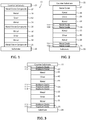
- Sample A contains a film stack as outlined in FIG. 4 .
- This film stack is commercially available as LX70 under the tradename SOLMOX and is obtainable from SolarGard Corporation.
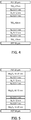
- Sample B contains the same film stack outlined in FIG. 5 , which differs from the film stack of Sample A in that the titanium oxide layers are replaced with niobium oxide layers.
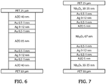
- Sample C contains the same film stack outlined in FIG. 6 , which differs from the film stack of Sample A in that the titanium oxide layers are replaced with AZO layers.
- Sample D contains the same film stack outlined in FIG. 7 , which differs from the film stack of Sample A in that the titanium dioxide layers are replaced with a metal oxide based composite layer including a niobium oxide layer and an AZO layer.
- Sample E contains the same film stack outlined in FIG. 8 , which differs from the film stack of Sample A in that the titanium dioxide layers are replaced with a metal oxide based composite layer including a titanium oxide layer and an AZO layer.
- Sample F contains the film stack outlined in FIG. 9 , which differs from the film stack of Sample A in that the titanium dioxide layers are replaced with a metal oxide based composite layer including a titanium oxide layer and a niobium oxide layer.
- Sample G contains the film stack outline in FIG. 10 , which differs from the film stack of Sample F in that the order of the titanium oxide layer and niobium oxide layers are switched.
- the layers are deposited by roll-to-roll (R2R) magnetron deposition with ceramic rotative targets for oxide materials.
- R2R roll-to-roll
- a small amount of oxygen is necessary to adjust the transparency of TiO x and Nb 2 O x .
- Example A-E are not according to the invention: Property Sample A Sample B Sample C Sample D Sample E Sample F Sample G Visual Light Transmittance (VLT) 72% 70% 64.5% 72% 74% 72% 72% Total Solar Energy Rejection (TSER) 55% 55% 63.0% 56% 56% 55% 55% Light to Solar Heat Gain Ratio 1.60 1.55 1.74 1.63 1.68 1.60 1.60 Visual Light Reflectance 11 9.4 12.6 9.4 11.4 10.5 10.4
Claims (13)
- Verbundfolie (10), umfassend eine Verbundschicht (25, 26, 27) auf Metalloxidbasis, eine Schicht (40, 42) auf Silberbasis und eine erste Schicht (30) auf Metallbasis, die zwischen der Verbundschicht (25, 26, 27) auf Metalloxidbasis und der ersten Schicht (40, 42) auf Silberbasis angeordnet ist, wobei die Verbundschicht (25, 26, 27) auf Metalloxidbasis eine Nioboxidschicht (102, 104, 113, 114, 115, 116) und eine Metalloxidschicht (101, 103) umfasst und wobei die Verbundfolie (10) eine Durchlässigkeit für sichtbares Licht von mindestens 65 % aufweist.
- Verbundfolie (10), umfassend:a. eine transparente Substratschicht (20), umfassend ein Polymer;b. eine oder mehrere Schichten (30, 32, 34, 36) auf Metallbasis;c. eine oder mehrere Schichten (40, 42) auf Silberbasis;d. eine oder mehrere Verbundschichten (25, 26, 27) auf Metalloxidbasis, wobei die eine oder die mehreren Verbundschichten (25, 26, 27) auf Metalloxidbasis mindestens zwei unterschiedliche Schichten verschiedener Metalloxide umfassen und wobei die eine oder die mehreren Verbundschichten (25, 26, 27) auf Metalloxidbasis eine Nioboxidschicht (102, 104, 113, 114, 115, 116) umfassen; undwobei die Verbundfolie (10) eine Durchlässigkeit für sichtbares Licht von mindestens 65 % aufweist.
- Verbundfolie (10) nach Anspruch 1 oder 2, wobei die Verbundfolie (10) eine erste Schicht (30) auf Metallbasis und eine zweite Schicht (32) auf Metallbasis umfasst und wobei die erste Schicht (30) auf Metallbasis und die zweite Schicht (32) auf Metallbasis in direktem Kontakt mit einer der einen oder der mehreren Schichten (40, 42) auf Silberbasis stehen.
- Verbundfolie (10) nach Anspruch 1 oder 2, wobei die Verbundfolie (10) eine erste Schicht (40) auf Silberbasis, eine zweite Schicht (42) auf Silberbasis, eine dritte Schicht (34) auf Metallbasis und eine vierte Schicht (36) auf Metallbasis umfasst und wobei die dritte Schicht (34) auf Metallbasis und die vierte Schicht (1036) auf Metallbasis in direktem Kontakt mit der zweiten Schicht (42) auf Silberbasis stehen.
- Verbundfolie (10) nach Anspruch 1 oder 2, wobei die Verbundfolie (10) eine oder mehrere Schichten auf Zinkoxidbasis umfasst, die AZO umfassen.
- Verbundfolie (10) nach Anspruch 1, wobei die eine oder die mehreren Verbundschichten (25, 26, 27) auf Metalloxidbasis eine Metalloxidschicht umfassen, die Nioboxid (113, 114, 115, 116) und eine Metalloxidschicht umfasst, die Zinkoxid in derselben Verbundschicht (25, 26, 27) auf Metalloxidbasis umfasst.
- Verbundfolie (10) nach Anspruch 1, wobei die eine oder die mehreren Verbundschichten (25, 26, 27) auf Metalloxidbasis eine Metalloxidschicht umfassen, die Titanoxid (110, 111, 112) und eine Metalloxidschicht umfasst, die Zinkoxid in derselben Verbundschicht (25, 26, 27) auf Metalloxidbasis umfasst.
- Verbundfolie (10) nach Anspruch 1, wobei die eine oder die mehreren Verbundschichten (25, 26, 27) auf Metalloxidbasis eine Metalloxidschicht umfassen, die Nioboxid (113, 114, 115, 116) und eine Metalloxidschicht umfasst, die Zinkoxid (110, 111, 112) in derselben Verbundschicht (25, 26, 27) auf Metalloxidbasis umfasst.
- Verbundfolie (10) nach Anspruch 1, wobei die eine oder die mehreren Verbundschichten (25, 26, 27) auf Metalloxidbasis eine Metalloxidschicht umfassen, die Nioboxid (113, 114, 115, 116) und eine Metalloxidschicht umfasst, die Titanoxid (110, 111, 112) in derselben Verbundschicht (25, 26, 27) auf Metalloxidbasis umfasst, und wobei die Dicke der Titanoxidschicht (110, 111, 112) geringer als die Dicke der Nioboxidschicht (113, 114, 115, 116) in derselben Verbundschicht (25, 26, 27) auf Metalloxidbasis ist.
- Verbundfolie (10) nach Anspruch 1, wobei die eine oder die mehreren Verbundschichten (25, 26, 27) auf Metalloxidbasis eine Metalloxidschicht umfassen, die ein Zinkoxid und eine Metalloxidschicht umfasst, die Titanoxid (110, 111, 112) oder Nioboxid (113, 114, 115, 116) in derselben Verbundschicht (25, 26, 27) auf Metalloxidbasis umfasst, wobei die Dicke der Zinkoxidschicht geringer als die Dicke der Nioboxidschicht (113, 114, 115, 116) oder Titanoxidschicht (110, 111, 112) in derselben Verbundschicht (25, 26, 27) auf Metalloxidbasis ist.
- Verbundfolie (10) nach Anspruch 1 oder 2, wobei die Verbundfolie (10) bei jeder Schicht (40, 42) auf Silberbasis eine Schicht auf Zinkoxidbasis umfasst.
- Verbundfolie (10) nach Anspruch 1 oder 2, wobei die Verbundfolie (10) eine oder mehrere Schichten auf Zinkoxidbasis umfasst, die benachbart zu einer Schicht (30, 32, 34, 36) auf Metallbasis angeordnet sind.
- Verbundfolie (10) nach Anspruch 1 oder 2, wobei die Verbundfolie (10) eine Schicht (110, 112) auf Titanoxidbasis umfasst, die benachbart zu einer Substratschicht (20, 22) angeordnet ist.
Priority Applications (1)
| Application Number | Priority Date | Filing Date | Title |
|---|---|---|---|
| EP21151647.1A EP3851274A1 (de) | 2013-12-30 | 2014-12-18 | Optischer film mit verbessertem licht-zu-solareintragswärme-verhältnis |
Applications Claiming Priority (2)
| Application Number | Priority Date | Filing Date | Title |
|---|---|---|---|
| US201361921790P | 2013-12-30 | 2013-12-30 | |
| PCT/US2014/071123 WO2015102923A1 (en) | 2013-12-30 | 2014-12-18 | Optical film exhibiting improved light to solar gain heat ratio |
Related Child Applications (1)
| Application Number | Title | Priority Date | Filing Date |
|---|---|---|---|
| EP21151647.1A Division EP3851274A1 (de) | 2013-12-30 | 2014-12-18 | Optischer film mit verbessertem licht-zu-solareintragswärme-verhältnis |
Publications (3)
| Publication Number | Publication Date |
|---|---|
| EP3089869A1 EP3089869A1 (de) | 2016-11-09 |
| EP3089869A4 EP3089869A4 (de) | 2017-07-12 |
| EP3089869B1 true EP3089869B1 (de) | 2021-01-27 |
Family
ID=53480830
Family Applications (2)
| Application Number | Title | Priority Date | Filing Date |
|---|---|---|---|
| EP21151647.1A Withdrawn EP3851274A1 (de) | 2013-12-30 | 2014-12-18 | Optischer film mit verbessertem licht-zu-solareintragswärme-verhältnis |
| EP14877504.2A Active EP3089869B1 (de) | 2013-12-30 | 2014-12-18 | Optischer film mit verbessertem licht-zu-solareintragswärme-verhältnis |
Family Applications Before (1)
| Application Number | Title | Priority Date | Filing Date |
|---|---|---|---|
| EP21151647.1A Withdrawn EP3851274A1 (de) | 2013-12-30 | 2014-12-18 | Optischer film mit verbessertem licht-zu-solareintragswärme-verhältnis |
Country Status (10)
| Country | Link |
|---|---|
| US (2) | US10081570B2 (de) |
| EP (2) | EP3851274A1 (de) |
| JP (1) | JP6346952B2 (de) |
| KR (1) | KR101920621B1 (de) |
| CN (2) | CN105873755B (de) |
| AU (2) | AU2014374185A1 (de) |
| ES (1) | ES2859578T3 (de) |
| IL (1) | IL246196A0 (de) |
| TW (1) | TWI577543B (de) |
| WO (1) | WO2015102923A1 (de) |
Families Citing this family (12)
| Publication number | Priority date | Publication date | Assignee | Title |
|---|---|---|---|---|
| TWI577543B (zh) | 2013-12-30 | 2017-04-11 | 聖高拜塑膠製品公司 | 展現改良的光對太陽能增益熱比率的光學膜 |
| EP3133649A1 (de) * | 2015-08-18 | 2017-02-22 | Saint-Gobain Performance Plastics Corporation | Flexibler funktionalisierter film |
| EP3136141A1 (de) * | 2015-08-26 | 2017-03-01 | Saint-Gobain Performance Plastics Corporation | Reflektierender infrarotfilm |
| US10591653B2 (en) * | 2016-02-05 | 2020-03-17 | Saint-Gobain Performance Plastics Corporation | Low corrosion solar control stack |
| KR101865471B1 (ko) * | 2016-09-09 | 2018-06-08 | 주식회사 넥스필 | 색상을 갖는 열차단 필름 및 그 제조방법 |
| WO2018051638A1 (ja) * | 2016-09-15 | 2018-03-22 | セントラル硝子株式会社 | 日射遮蔽部材 |
| US20180095208A1 (en) * | 2016-10-03 | 2018-04-05 | Saint-Gobain Performance Plastics Corporation | Solar control window film |
| LU100018B1 (en) | 2017-01-11 | 2018-08-14 | Luxembourg Inst Science & Tech List | Infrared reflective and electrical conductive composite film and manufacturing method thereof |
| CN106868462A (zh) * | 2017-03-01 | 2017-06-20 | 东莞市航晨纳米材料有限公司 | 一种合金复合材料及其制备方法 |
| KR102553880B1 (ko) * | 2017-08-07 | 2023-07-10 | 삼성디스플레이 주식회사 | 발광 소자 |
| FR3091701A1 (fr) * | 2019-01-14 | 2020-07-17 | Saint-Gobain Glass France | Substrat muni d’un empilement a proprietes thermiques et a couche absorbante |
| FR3121659B1 (fr) | 2021-04-09 | 2023-10-27 | Saint Gobain | Vitrage multiple d’enceinte pressurisée ayant un film de matériau polymère adhésif et antisolaire |
Family Cites Families (60)
| Publication number | Priority date | Publication date | Assignee | Title |
|---|---|---|---|---|
| GB498503A (en) * | 1936-04-06 | 1939-01-09 | Philips Nv | Improvements in or relating to photo-electric cells |
| US5183700A (en) | 1990-08-10 | 1993-02-02 | Viratec Thin Films, Inc. | Solar control properties in low emissivity coatings |
| EP0498884B1 (de) | 1990-08-30 | 1997-11-12 | Viratec Thin Films, Inc. | Verfahren zur abscheidung von nioboxid enthaltenden optischen beschichtungen mittels reaktiver gleichstromzerstäubung |
| US5296302A (en) | 1992-03-27 | 1994-03-22 | Cardinal Ig Company | Abrasion-resistant overcoat for coated substrates |
| WO1994021838A1 (en) * | 1993-03-23 | 1994-09-29 | Southwall Technologies Inc. | Gold-clad-silver-layer-containing films |
| DE4407502A1 (de) | 1994-03-07 | 1995-09-14 | Leybold Ag | Mehrlagige Beschichtung |
| FR2719036B1 (fr) | 1994-04-21 | 1996-05-24 | Saint Gobain Vitrage | Substrats en verre revêtus d'un empilement de couches minces, à propriétés de réflexion dans l'infra-rouge et/ou dans le domaine du rayonnement solaire. |
| FR2755962B1 (fr) | 1996-11-21 | 1998-12-24 | Saint Gobain Vitrage | Vitrage comprenant un substrat muni d'un empilement de couches minces pour la protection solaire et/ou l'isolation thermique |
| US6007901A (en) | 1997-12-04 | 1999-12-28 | Cpfilms, Inc. | Heat reflecting fenestration products with color corrective and corrosion protective layers |
| US6030671A (en) | 1998-01-09 | 2000-02-29 | Msc Specialty Films, Inc. | Low emissivity window films |
| US5956175A (en) | 1998-07-31 | 1999-09-21 | Msc Specialty Films Inc | Solar control window film |
| FR2784985B1 (fr) | 1998-10-22 | 2001-09-21 | Saint Gobain Vitrage | Substrat transparent muni d'un empilement de couches minces |
| EP1010677A1 (de) * | 1998-12-17 | 2000-06-21 | Saint-Gobain Vitrage | Wärmereflektierendes Mehrlagensystem für transparentes Substrat |
| US6261694B1 (en) * | 1999-03-17 | 2001-07-17 | General Electric Company | Infrared reflecting coatings |
| JP2000294980A (ja) | 1999-04-06 | 2000-10-20 | Nippon Sheet Glass Co Ltd | 透光性電磁波フィルタおよびその製造方法 |
| US20020136905A1 (en) | 1999-11-24 | 2002-09-26 | Medwick Paul A. | Low shading coefficient and low emissivity coatings and coated articles |
| US6887575B2 (en) * | 2001-10-17 | 2005-05-03 | Guardian Industries Corp. | Heat treatable coated article with zinc oxide inclusive contact layer(s) |
| US7267879B2 (en) * | 2001-02-28 | 2007-09-11 | Guardian Industries Corp. | Coated article with silicon oxynitride adjacent glass |
| US6576349B2 (en) | 2000-07-10 | 2003-06-10 | Guardian Industries Corp. | Heat treatable low-E coated articles and methods of making same |
| US6589658B1 (en) | 2001-11-29 | 2003-07-08 | Guardian Industries Corp. | Coated article with anti-reflective layer(s) system |
| DE60305730T2 (de) * | 2002-11-05 | 2007-05-31 | N.V. Bekaert S.A. | Infrarotreflektierende geschichtete struktur |
| US7419725B2 (en) | 2004-09-01 | 2008-09-02 | Guardian Industries Corp. | Coated article with low-E coating including IR reflecting layer(s) and corresponding method |
| EP1849594B1 (de) * | 2005-02-17 | 2011-09-28 | Asahi Glass Company, Limited | Leitfähiger laminierter körper, folie zur abschirmung von elektromagnetischen wellen für plasmaanzeige und schutzplatte für plasmaanzeige |
| EP1860930A4 (de) | 2005-02-25 | 2009-12-23 | Asahi Glass Co Ltd | Elektromagnetisch abschirmendes laminat und display damit |
| KR101407126B1 (ko) | 2005-05-11 | 2014-06-13 | 에이쥐씨 글래스 유럽 | 태양광 차단 스택 |
| WO2007020792A1 (ja) | 2005-08-16 | 2007-02-22 | Asahi Glass Company, Limited | 赤外線反射ガラス板および車両窓用合わせガラス |
| CN101243023B (zh) | 2005-08-16 | 2012-07-18 | 旭硝子株式会社 | 车窗用夹层玻璃 |
| WO2007028060A2 (en) | 2005-09-02 | 2007-03-08 | Southwall Technologies, Inc. | Durable near-infrared blocking and emi shielding film for display filter |
| US7508586B2 (en) | 2006-04-14 | 2009-03-24 | Southwall Technologies, Inc. | Zinc-based film manipulation for an optical filter |
| JP4893097B2 (ja) * | 2006-05-01 | 2012-03-07 | 旭硝子株式会社 | 導電性積層体およびプラズマディスプレイ用保護板 |
| KR100926233B1 (ko) * | 2006-05-30 | 2009-11-09 | 삼성코닝정밀유리 주식회사 | 다층박막 구조를 갖는 피디피 필터 및 그 제조방법 |
| US20070281170A1 (en) | 2006-06-06 | 2007-12-06 | 3M Innovative Properties Company | Infrared radiation reflecting insulated glazing unit |
| US7919158B2 (en) | 2006-06-06 | 2011-04-05 | 3M Innovative Properties Company | Infrared radiation reflecting insulated glazing unit |
| JP2008036864A (ja) * | 2006-08-02 | 2008-02-21 | Oike Ind Co Ltd | 積層体、及び該積層体を用いた合わせガラス並びに板ガラス |
| CN100576408C (zh) | 2006-12-28 | 2009-12-30 | 甘国工 | 等离子体显示器滤光板及使用该滤光板的显示器 |
| US7807248B2 (en) | 2007-08-14 | 2010-10-05 | Cardinal Cg Company | Solar control low-emissivity coatings |
| JP2009071146A (ja) * | 2007-09-14 | 2009-04-02 | Asahi Glass Co Ltd | 導電性積層体およびプラズマディスプレイ用保護板 |
| US20090153989A1 (en) | 2007-12-14 | 2009-06-18 | Samsung Corning Precision Glass Co., Ltd. | Optical filter for display device |
| CN101909873B (zh) | 2007-12-28 | 2016-10-19 | 3M创新有限公司 | 用于阳光控制及其它用途的红外线反射膜 |
| FR2928147B1 (fr) | 2008-02-29 | 2011-04-01 | Saint Gobain | Substrat texture muni d'un empilement a proprietes thermiques |
| US7824777B2 (en) | 2008-03-26 | 2010-11-02 | Southwall Technologies, Inc. | Robust optical filter utilizing pairs of dielectric and metallic layers |
| WO2010053921A1 (en) * | 2008-11-04 | 2010-05-14 | Apogee Enterprises, Inc. | Coated glass surfaces and method for coating a glass substrate |
| WO2010055832A1 (ja) * | 2008-11-11 | 2010-05-20 | 旭硝子株式会社 | 導電性積層体及びプラズマディスプレイ用保護板 |
| US20150103398A1 (en) | 2009-02-19 | 2015-04-16 | Toyota Motor Engineering & Manufacturing North America, Inc. | Ir reflective coating compatible to ir sensors |
| FR2942794B1 (fr) * | 2009-03-09 | 2011-02-18 | Saint Gobain | Substrat muni d'un empilement a proprietes thermiques comportant des couches a haut indice de refraction |
| EP2472295A4 (de) * | 2009-08-26 | 2015-09-16 | Sumitomo Riko Co Ltd | Transparenter laminatfilm und herstellungsverfahren dafür |
| US8337988B2 (en) | 2010-04-22 | 2012-12-25 | Centre Luxembourgeois De Recherches Pour Le Verre Et La Ceramique S.A. (C.R.V.C.) | Coated article having low-E coating with absorber layer(s) |
| CN101866063B (zh) | 2010-06-02 | 2012-05-02 | 温州医学院 | 一种具有抗红外作用的树脂镜片及其制备方法 |
| TWI520354B (zh) * | 2010-12-16 | 2016-02-01 | 財團法人工業技術研究院 | 堆疊電極以及光電元件 |
| MX345677B (es) | 2011-03-24 | 2017-02-10 | Saint Gobain | Sustrato transparente proporcionado con una multicapa de pelicula delgada. |
| DE102011116191A1 (de) | 2011-10-13 | 2013-04-18 | Southwall Europe Gmbh | Mehrschichtsysteme für eine selektive Reflexion elektromagnetischer Strahlung aus dem Wellenlängenspektrum des Sonnenlichts und Verfahren zu seiner Herstellung |
| DE202011109312U1 (de) | 2011-12-15 | 2012-01-23 | Southwall Technologies, Inc. | Verbundglas für die Anwendung in Fahrzeugen oder derArchitektur |
| KR20140138137A (ko) * | 2012-02-28 | 2014-12-03 | 아사히 가라스 가부시키가이샤 | 적층체의 제조 방법, 및 적층체 |
| JPWO2013129335A1 (ja) | 2012-02-29 | 2015-07-30 | コニカミノルタ株式会社 | 近赤外反射フィルムおよびこれを用いた近赤外反射ガラス |
| US9499899B2 (en) | 2013-03-13 | 2016-11-22 | Intermolecular, Inc. | Systems, methods, and apparatus for production coatings of low-emissivity glass including a ternary alloy |
| US9790127B2 (en) * | 2013-03-14 | 2017-10-17 | Intermolecular, Inc. | Method to generate high LSG low-emissivity coating with same color after heat treatment |
| WO2014191472A2 (en) | 2013-05-30 | 2014-12-04 | Agc Glass Europe | Low-emissivity glazing |
| TWI577543B (zh) | 2013-12-30 | 2017-04-11 | 聖高拜塑膠製品公司 | 展現改良的光對太陽能增益熱比率的光學膜 |
| US20170254936A1 (en) | 2014-08-22 | 2017-09-07 | Konica Minolta, Inc. | Light reflecting film, production method for light reflecting film, decorative molding method for light reflecting film, laminated glass, and curved surface body |
| EP3136141A1 (de) | 2015-08-26 | 2017-03-01 | Saint-Gobain Performance Plastics Corporation | Reflektierender infrarotfilm |
-
2014
- 2014-12-08 TW TW103142672A patent/TWI577543B/zh not_active IP Right Cessation
- 2014-12-18 AU AU2014374185A patent/AU2014374185A1/en not_active Abandoned
- 2014-12-18 WO PCT/US2014/071123 patent/WO2015102923A1/en active Application Filing
- 2014-12-18 EP EP21151647.1A patent/EP3851274A1/de not_active Withdrawn
- 2014-12-18 CN CN201480070364.5A patent/CN105873755B/zh not_active Expired - Fee Related
- 2014-12-18 EP EP14877504.2A patent/EP3089869B1/de active Active
- 2014-12-18 US US14/575,049 patent/US10081570B2/en active Active
- 2014-12-18 KR KR1020167018347A patent/KR101920621B1/ko active IP Right Grant
- 2014-12-18 JP JP2016542267A patent/JP6346952B2/ja not_active Expired - Fee Related
- 2014-12-18 CN CN201810916659.XA patent/CN109095787B/zh not_active Expired - Fee Related
- 2014-12-18 ES ES14877504T patent/ES2859578T3/es active Active
-
2016
- 2016-06-14 IL IL246196A patent/IL246196A0/en unknown
-
2017
- 2017-09-11 AU AU2017225164A patent/AU2017225164B2/en not_active Ceased
-
2018
- 2018-08-22 US US16/108,789 patent/US11214514B2/en active Active
Non-Patent Citations (1)
| Title |
|---|
| None * |
Also Published As
| Publication number | Publication date |
|---|---|
| US20150183301A1 (en) | 2015-07-02 |
| EP3089869A1 (de) | 2016-11-09 |
| WO2015102923A1 (en) | 2015-07-09 |
| CN109095787A (zh) | 2018-12-28 |
| AU2017225164A1 (en) | 2017-10-05 |
| TW201524756A (zh) | 2015-07-01 |
| AU2017225164B2 (en) | 2019-03-14 |
| US10081570B2 (en) | 2018-09-25 |
| KR20160099606A (ko) | 2016-08-22 |
| EP3089869A4 (de) | 2017-07-12 |
| US20180362395A1 (en) | 2018-12-20 |
| JP2017501908A (ja) | 2017-01-19 |
| CN109095787B (zh) | 2021-11-23 |
| IL246196A0 (en) | 2016-07-31 |
| CN105873755A (zh) | 2016-08-17 |
| KR101920621B1 (ko) | 2018-11-22 |
| ES2859578T3 (es) | 2021-10-04 |
| US11214514B2 (en) | 2022-01-04 |
| AU2014374185A1 (en) | 2016-07-21 |
| EP3851274A1 (de) | 2021-07-21 |
| TWI577543B (zh) | 2017-04-11 |
| CN105873755B (zh) | 2018-09-14 |
| JP6346952B2 (ja) | 2018-06-20 |
Similar Documents
| Publication | Publication Date | Title |
|---|---|---|
| US11214514B2 (en) | Optical film exhibiting improved light to solar gain heat ratio | |
| EP2089743B1 (de) | Film zur kontrolle der sonneneinstrahlung | |
| EP2822907B1 (de) | Kraftfahrzeugscheibe mit wärmestrahlung reflektierender beschichtung | |
| US20150185382A1 (en) | Composite film having superior optical and solar performance | |
| US10571610B2 (en) | Infra-red control optical films having metal nitride between encapsulating layers containing oxide | |
| WO2014160414A1 (en) | Low-emissivity glass including spacer dielectric layers compatible with heat treatment | |
| JP2018507441A (ja) | 強化された太陽光制御性能を備えた太陽光制御コーティング | |
| KR20050084671A (ko) | 적외선 반사층 구조 | |
| US10175397B2 (en) | Optical film including an infrared absorption layer | |
| CN104203856A (zh) | 遮阳玻璃制品 | |
| JP6673349B2 (ja) | 膜積層体および合わせガラス | |
| EP2862844A1 (de) | Transparenter mehrschichtiger körper mit geringer emissivität und baumaterial damit | |
| KR20190032570A (ko) | 지르코늄이 강화된 규소-지르코늄 질화물을 포함하는 층을 적어도 하나 포함하는, 열적 특성을 갖는 스택을 구비한 기판, 그 용도 및 그 제조 |
Legal Events
| Date | Code | Title | Description |
|---|---|---|---|
| PUAI | Public reference made under article 153(3) epc to a published international application that has entered the european phase |
Free format text: ORIGINAL CODE: 0009012 |
|
| 17P | Request for examination filed |
Effective date: 20160722 |
|
| AK | Designated contracting states |
Kind code of ref document: A1 Designated state(s): AL AT BE BG CH CY CZ DE DK EE ES FI FR GB GR HR HU IE IS IT LI LT LU LV MC MK MT NL NO PL PT RO RS SE SI SK SM TR |
|
| AX | Request for extension of the european patent |
Extension state: BA ME |
|
| RIN1 | Information on inventor provided before grant (corrected) |
Inventor name: LEYDER, CHARLES Inventor name: DIGUET, ANTOINE Inventor name: LIENHART, FABIEN |
|
| DAX | Request for extension of the european patent (deleted) | ||
| A4 | Supplementary search report drawn up and despatched |
Effective date: 20170609 |
|
| RIC1 | Information provided on ipc code assigned before grant |
Ipc: B32B 7/02 20060101AFI20170602BHEP Ipc: B32B 33/00 20060101ALI20170602BHEP Ipc: C03C 17/36 20060101ALI20170602BHEP |
|
| GRAP | Despatch of communication of intention to grant a patent |
Free format text: ORIGINAL CODE: EPIDOSNIGR1 |
|
| STAA | Information on the status of an ep patent application or granted ep patent |
Free format text: STATUS: GRANT OF PATENT IS INTENDED |
|
| INTG | Intention to grant announced |
Effective date: 20200910 |
|
| GRAS | Grant fee paid |
Free format text: ORIGINAL CODE: EPIDOSNIGR3 |
|
| GRAA | (expected) grant |
Free format text: ORIGINAL CODE: 0009210 |
|
| STAA | Information on the status of an ep patent application or granted ep patent |
Free format text: STATUS: THE PATENT HAS BEEN GRANTED |
|
| AK | Designated contracting states |
Kind code of ref document: B1 Designated state(s): AL AT BE BG CH CY CZ DE DK EE ES FI FR GB GR HR HU IE IS IT LI LT LU LV MC MK MT NL NO PL PT RO RS SE SI SK SM TR |
|
| REG | Reference to a national code |
Ref country code: GB Ref legal event code: FG4D |
|
| REG | Reference to a national code |
Ref country code: CH Ref legal event code: EP |
|
| REG | Reference to a national code |
Ref country code: AT Ref legal event code: REF Ref document number: 1357975 Country of ref document: AT Kind code of ref document: T Effective date: 20210215 |
|
| REG | Reference to a national code |
Ref country code: IE Ref legal event code: FG4D |
|
| REG | Reference to a national code |
Ref country code: DE Ref legal event code: R096 Ref document number: 602014074654 Country of ref document: DE |
|
| REG | Reference to a national code |
Ref country code: SE Ref legal event code: TRGR |
|
| REG | Reference to a national code |
Ref country code: NL Ref legal event code: MP Effective date: 20210127 |
|
| REG | Reference to a national code |
Ref country code: LT Ref legal event code: MG9D |
|
| REG | Reference to a national code |
Ref country code: AT Ref legal event code: MK05 Ref document number: 1357975 Country of ref document: AT Kind code of ref document: T Effective date: 20210127 |
|
| PG25 | Lapsed in a contracting state [announced via postgrant information from national office to epo] |
Ref country code: HR Free format text: LAPSE BECAUSE OF FAILURE TO SUBMIT A TRANSLATION OF THE DESCRIPTION OR TO PAY THE FEE WITHIN THE PRESCRIBED TIME-LIMIT Effective date: 20210127 Ref country code: GR Free format text: LAPSE BECAUSE OF FAILURE TO SUBMIT A TRANSLATION OF THE DESCRIPTION OR TO PAY THE FEE WITHIN THE PRESCRIBED TIME-LIMIT Effective date: 20210428 Ref country code: FI Free format text: LAPSE BECAUSE OF FAILURE TO SUBMIT A TRANSLATION OF THE DESCRIPTION OR TO PAY THE FEE WITHIN THE PRESCRIBED TIME-LIMIT Effective date: 20210127 Ref country code: PT Free format text: LAPSE BECAUSE OF FAILURE TO SUBMIT A TRANSLATION OF THE DESCRIPTION OR TO PAY THE FEE WITHIN THE PRESCRIBED TIME-LIMIT Effective date: 20210527 Ref country code: LT Free format text: LAPSE BECAUSE OF FAILURE TO SUBMIT A TRANSLATION OF THE DESCRIPTION OR TO PAY THE FEE WITHIN THE PRESCRIBED TIME-LIMIT Effective date: 20210127 Ref country code: BG Free format text: LAPSE BECAUSE OF FAILURE TO SUBMIT A TRANSLATION OF THE DESCRIPTION OR TO PAY THE FEE WITHIN THE PRESCRIBED TIME-LIMIT Effective date: 20210427 Ref country code: NO Free format text: LAPSE BECAUSE OF FAILURE TO SUBMIT A TRANSLATION OF THE DESCRIPTION OR TO PAY THE FEE WITHIN THE PRESCRIBED TIME-LIMIT Effective date: 20210427 Ref country code: NL Free format text: LAPSE BECAUSE OF FAILURE TO SUBMIT A TRANSLATION OF THE DESCRIPTION OR TO PAY THE FEE WITHIN THE PRESCRIBED TIME-LIMIT Effective date: 20210127 |
|
| PG25 | Lapsed in a contracting state [announced via postgrant information from national office to epo] |
Ref country code: AT Free format text: LAPSE BECAUSE OF FAILURE TO SUBMIT A TRANSLATION OF THE DESCRIPTION OR TO PAY THE FEE WITHIN THE PRESCRIBED TIME-LIMIT Effective date: 20210127 Ref country code: PL Free format text: LAPSE BECAUSE OF FAILURE TO SUBMIT A TRANSLATION OF THE DESCRIPTION OR TO PAY THE FEE WITHIN THE PRESCRIBED TIME-LIMIT Effective date: 20210127 Ref country code: RS Free format text: LAPSE BECAUSE OF FAILURE TO SUBMIT A TRANSLATION OF THE DESCRIPTION OR TO PAY THE FEE WITHIN THE PRESCRIBED TIME-LIMIT Effective date: 20210127 Ref country code: LV Free format text: LAPSE BECAUSE OF FAILURE TO SUBMIT A TRANSLATION OF THE DESCRIPTION OR TO PAY THE FEE WITHIN THE PRESCRIBED TIME-LIMIT Effective date: 20210127 |
|
| PG25 | Lapsed in a contracting state [announced via postgrant information from national office to epo] |
Ref country code: IS Free format text: LAPSE BECAUSE OF FAILURE TO SUBMIT A TRANSLATION OF THE DESCRIPTION OR TO PAY THE FEE WITHIN THE PRESCRIBED TIME-LIMIT Effective date: 20210527 |
|
| REG | Reference to a national code |
Ref country code: ES Ref legal event code: FG2A Ref document number: 2859578 Country of ref document: ES Kind code of ref document: T3 Effective date: 20211004 |
|
| REG | Reference to a national code |
Ref country code: DE Ref legal event code: R097 Ref document number: 602014074654 Country of ref document: DE |
|
| PG25 | Lapsed in a contracting state [announced via postgrant information from national office to epo] |
Ref country code: SM Free format text: LAPSE BECAUSE OF FAILURE TO SUBMIT A TRANSLATION OF THE DESCRIPTION OR TO PAY THE FEE WITHIN THE PRESCRIBED TIME-LIMIT Effective date: 20210127 Ref country code: CZ Free format text: LAPSE BECAUSE OF FAILURE TO SUBMIT A TRANSLATION OF THE DESCRIPTION OR TO PAY THE FEE WITHIN THE PRESCRIBED TIME-LIMIT Effective date: 20210127 Ref country code: EE Free format text: LAPSE BECAUSE OF FAILURE TO SUBMIT A TRANSLATION OF THE DESCRIPTION OR TO PAY THE FEE WITHIN THE PRESCRIBED TIME-LIMIT Effective date: 20210127 |
|
| PG25 | Lapsed in a contracting state [announced via postgrant information from national office to epo] |
Ref country code: RO Free format text: LAPSE BECAUSE OF FAILURE TO SUBMIT A TRANSLATION OF THE DESCRIPTION OR TO PAY THE FEE WITHIN THE PRESCRIBED TIME-LIMIT Effective date: 20210127 Ref country code: SK Free format text: LAPSE BECAUSE OF FAILURE TO SUBMIT A TRANSLATION OF THE DESCRIPTION OR TO PAY THE FEE WITHIN THE PRESCRIBED TIME-LIMIT Effective date: 20210127 Ref country code: DK Free format text: LAPSE BECAUSE OF FAILURE TO SUBMIT A TRANSLATION OF THE DESCRIPTION OR TO PAY THE FEE WITHIN THE PRESCRIBED TIME-LIMIT Effective date: 20210127 |
|
| PLBE | No opposition filed within time limit |
Free format text: ORIGINAL CODE: 0009261 |
|
| STAA | Information on the status of an ep patent application or granted ep patent |
Free format text: STATUS: NO OPPOSITION FILED WITHIN TIME LIMIT |
|
| 26N | No opposition filed |
Effective date: 20211028 |
|
| PG25 | Lapsed in a contracting state [announced via postgrant information from national office to epo] |
Ref country code: AL Free format text: LAPSE BECAUSE OF FAILURE TO SUBMIT A TRANSLATION OF THE DESCRIPTION OR TO PAY THE FEE WITHIN THE PRESCRIBED TIME-LIMIT Effective date: 20210127 |
|
| PGFP | Annual fee paid to national office [announced via postgrant information from national office to epo] |
Ref country code: SE Payment date: 20211119 Year of fee payment: 8 Ref country code: FR Payment date: 20211117 Year of fee payment: 8 Ref country code: DE Payment date: 20211117 Year of fee payment: 8 Ref country code: GB Payment date: 20211118 Year of fee payment: 8 |
|
| PG25 | Lapsed in a contracting state [announced via postgrant information from national office to epo] |
Ref country code: SI Free format text: LAPSE BECAUSE OF FAILURE TO SUBMIT A TRANSLATION OF THE DESCRIPTION OR TO PAY THE FEE WITHIN THE PRESCRIBED TIME-LIMIT Effective date: 20210127 |
|
| PGFP | Annual fee paid to national office [announced via postgrant information from national office to epo] |
Ref country code: BE Payment date: 20211122 Year of fee payment: 8 |
|
| PG25 | Lapsed in a contracting state [announced via postgrant information from national office to epo] |
Ref country code: IT Free format text: LAPSE BECAUSE OF FAILURE TO SUBMIT A TRANSLATION OF THE DESCRIPTION OR TO PAY THE FEE WITHIN THE PRESCRIBED TIME-LIMIT Effective date: 20210127 |
|
| PG25 | Lapsed in a contracting state [announced via postgrant information from national office to epo] |
Ref country code: IS Free format text: LAPSE BECAUSE OF FAILURE TO SUBMIT A TRANSLATION OF THE DESCRIPTION OR TO PAY THE FEE WITHIN THE PRESCRIBED TIME-LIMIT Effective date: 20210527 |
|
| PGFP | Annual fee paid to national office [announced via postgrant information from national office to epo] |
Ref country code: ES Payment date: 20220103 Year of fee payment: 8 |
|
| PG25 | Lapsed in a contracting state [announced via postgrant information from national office to epo] |
Ref country code: MC Free format text: LAPSE BECAUSE OF FAILURE TO SUBMIT A TRANSLATION OF THE DESCRIPTION OR TO PAY THE FEE WITHIN THE PRESCRIBED TIME-LIMIT Effective date: 20210127 |
|
| REG | Reference to a national code |
Ref country code: CH Ref legal event code: PL |
|
| PG25 | Lapsed in a contracting state [announced via postgrant information from national office to epo] |
Ref country code: LU Free format text: LAPSE BECAUSE OF NON-PAYMENT OF DUE FEES Effective date: 20211218 Ref country code: IE Free format text: LAPSE BECAUSE OF NON-PAYMENT OF DUE FEES Effective date: 20211218 |
|
| PG25 | Lapsed in a contracting state [announced via postgrant information from national office to epo] |
Ref country code: LI Free format text: LAPSE BECAUSE OF NON-PAYMENT OF DUE FEES Effective date: 20211231 Ref country code: CH Free format text: LAPSE BECAUSE OF NON-PAYMENT OF DUE FEES Effective date: 20211231 |
|
| PG25 | Lapsed in a contracting state [announced via postgrant information from national office to epo] |
Ref country code: HU Free format text: LAPSE BECAUSE OF FAILURE TO SUBMIT A TRANSLATION OF THE DESCRIPTION OR TO PAY THE FEE WITHIN THE PRESCRIBED TIME-LIMIT; INVALID AB INITIO Effective date: 20141218 |
|
| PG25 | Lapsed in a contracting state [announced via postgrant information from national office to epo] |
Ref country code: CY Free format text: LAPSE BECAUSE OF FAILURE TO SUBMIT A TRANSLATION OF THE DESCRIPTION OR TO PAY THE FEE WITHIN THE PRESCRIBED TIME-LIMIT Effective date: 20210127 |
|
| REG | Reference to a national code |
Ref country code: DE Ref legal event code: R119 Ref document number: 602014074654 Country of ref document: DE |
|
| REG | Reference to a national code |
Ref country code: SE Ref legal event code: EUG |
|
| GBPC | Gb: european patent ceased through non-payment of renewal fee |
Effective date: 20221218 |
|
| REG | Reference to a national code |
Ref country code: BE Ref legal event code: MM Effective date: 20221231 |
|
| PG25 | Lapsed in a contracting state [announced via postgrant information from national office to epo] |
Ref country code: SE Free format text: LAPSE BECAUSE OF NON-PAYMENT OF DUE FEES Effective date: 20221219 Ref country code: GB Free format text: LAPSE BECAUSE OF NON-PAYMENT OF DUE FEES Effective date: 20221218 Ref country code: DE Free format text: LAPSE BECAUSE OF NON-PAYMENT OF DUE FEES Effective date: 20230701 |
|
| PG25 | Lapsed in a contracting state [announced via postgrant information from national office to epo] |
Ref country code: FR Free format text: LAPSE BECAUSE OF NON-PAYMENT OF DUE FEES Effective date: 20221231 Ref country code: BE Free format text: LAPSE BECAUSE OF NON-PAYMENT OF DUE FEES Effective date: 20221231 |
|
| PG25 | Lapsed in a contracting state [announced via postgrant information from national office to epo] |
Ref country code: ES Free format text: LAPSE BECAUSE OF NON-PAYMENT OF DUE FEES Effective date: 20221219 |
|
| PG25 | Lapsed in a contracting state [announced via postgrant information from national office to epo] |
Ref country code: MK Free format text: LAPSE BECAUSE OF FAILURE TO SUBMIT A TRANSLATION OF THE DESCRIPTION OR TO PAY THE FEE WITHIN THE PRESCRIBED TIME-LIMIT Effective date: 20210127 Ref country code: ES Free format text: LAPSE BECAUSE OF NON-PAYMENT OF DUE FEES Effective date: 20221219 |