EP3089859B1 - Procede pour la fixation d'un element sur un pion - Google Patents
Procede pour la fixation d'un element sur un pion Download PDFInfo
- Publication number
- EP3089859B1 EP3089859B1 EP14835484.8A EP14835484A EP3089859B1 EP 3089859 B1 EP3089859 B1 EP 3089859B1 EP 14835484 A EP14835484 A EP 14835484A EP 3089859 B1 EP3089859 B1 EP 3089859B1
- Authority
- EP
- European Patent Office
- Prior art keywords
- pin
- pins
- group
- wall
- rivet
- Prior art date
- Legal status (The legal status is an assumption and is not a legal conclusion. Google has not performed a legal analysis and makes no representation as to the accuracy of the status listed.)
- Active
Links
- 238000000034 method Methods 0.000 title claims description 43
- 239000012528 membrane Substances 0.000 claims description 12
- 239000004033 plastic Substances 0.000 claims description 9
- 229920003023 plastic Polymers 0.000 claims description 9
- 230000000149 penetrating effect Effects 0.000 claims description 8
- 238000005096 rolling process Methods 0.000 claims 2
- 241000920340 Pion Species 0.000 description 32
- 238000010438 heat treatment Methods 0.000 description 19
- 238000004804 winding Methods 0.000 description 11
- 239000007788 liquid Substances 0.000 description 6
- 239000000463 material Substances 0.000 description 6
- 230000008569 process Effects 0.000 description 5
- 230000009471 action Effects 0.000 description 4
- 238000002844 melting Methods 0.000 description 4
- 230000008018 melting Effects 0.000 description 4
- 241001080024 Telles Species 0.000 description 3
- 229920001903 high density polyethylene Polymers 0.000 description 3
- 239000004700 high-density polyethylene Substances 0.000 description 3
- XSQUKJJJFZCRTK-UHFFFAOYSA-N Urea Chemical compound NC(N)=O XSQUKJJJFZCRTK-UHFFFAOYSA-N 0.000 description 2
- 239000004202 carbamide Substances 0.000 description 2
- 230000006835 compression Effects 0.000 description 2
- 238000007906 compression Methods 0.000 description 2
- 238000001816 cooling Methods 0.000 description 2
- 230000000694 effects Effects 0.000 description 2
- 239000004744 fabric Substances 0.000 description 2
- 239000000835 fiber Substances 0.000 description 2
- 235000011837 pasties Nutrition 0.000 description 2
- 230000000750 progressive effect Effects 0.000 description 2
- 235000001674 Agaricus brunnescens Nutrition 0.000 description 1
- 239000011324 bead Substances 0.000 description 1
- 238000010531 catalytic reduction reaction Methods 0.000 description 1
- 239000000155 melt Substances 0.000 description 1
- 239000002184 metal Substances 0.000 description 1
- 238000003825 pressing Methods 0.000 description 1
- 230000001105 regulatory effect Effects 0.000 description 1
- 239000007787 solid Substances 0.000 description 1
- 230000007480 spreading Effects 0.000 description 1
Images


Classifications
-
- B—PERFORMING OPERATIONS; TRANSPORTING
- B29—WORKING OF PLASTICS; WORKING OF SUBSTANCES IN A PLASTIC STATE IN GENERAL
- B29C—SHAPING OR JOINING OF PLASTICS; SHAPING OF MATERIAL IN A PLASTIC STATE, NOT OTHERWISE PROVIDED FOR; AFTER-TREATMENT OF THE SHAPED PRODUCTS, e.g. REPAIRING
- B29C65/00—Joining or sealing of preformed parts, e.g. welding of plastics materials; Apparatus therefor
- B29C65/56—Joining or sealing of preformed parts, e.g. welding of plastics materials; Apparatus therefor using mechanical means or mechanical connections, e.g. form-fits
- B29C65/60—Riveting or staking
- B29C65/606—Riveting or staking the rivets being integral with one of the parts to be joined, i.e. staking
-
- B—PERFORMING OPERATIONS; TRANSPORTING
- B29—WORKING OF PLASTICS; WORKING OF SUBSTANCES IN A PLASTIC STATE IN GENERAL
- B29C—SHAPING OR JOINING OF PLASTICS; SHAPING OF MATERIAL IN A PLASTIC STATE, NOT OTHERWISE PROVIDED FOR; AFTER-TREATMENT OF THE SHAPED PRODUCTS, e.g. REPAIRING
- B29C65/00—Joining or sealing of preformed parts, e.g. welding of plastics materials; Apparatus therefor
- B29C65/02—Joining or sealing of preformed parts, e.g. welding of plastics materials; Apparatus therefor by heating, with or without pressure
- B29C65/18—Joining or sealing of preformed parts, e.g. welding of plastics materials; Apparatus therefor by heating, with or without pressure using heated tools
-
- B—PERFORMING OPERATIONS; TRANSPORTING
- B29—WORKING OF PLASTICS; WORKING OF SUBSTANCES IN A PLASTIC STATE IN GENERAL
- B29C—SHAPING OR JOINING OF PLASTICS; SHAPING OF MATERIAL IN A PLASTIC STATE, NOT OTHERWISE PROVIDED FOR; AFTER-TREATMENT OF THE SHAPED PRODUCTS, e.g. REPAIRING
- B29C65/00—Joining or sealing of preformed parts, e.g. welding of plastics materials; Apparatus therefor
- B29C65/82—Testing the joint
- B29C65/8207—Testing the joint by mechanical methods
-
- B—PERFORMING OPERATIONS; TRANSPORTING
- B29—WORKING OF PLASTICS; WORKING OF SUBSTANCES IN A PLASTIC STATE IN GENERAL
- B29C—SHAPING OR JOINING OF PLASTICS; SHAPING OF MATERIAL IN A PLASTIC STATE, NOT OTHERWISE PROVIDED FOR; AFTER-TREATMENT OF THE SHAPED PRODUCTS, e.g. REPAIRING
- B29C66/00—General aspects of processes or apparatus for joining preformed parts
- B29C66/01—General aspects dealing with the joint area or with the area to be joined
- B29C66/02—Preparation of the material, in the area to be joined, prior to joining or welding
- B29C66/022—Mechanical pre-treatments, e.g. reshaping
- B29C66/0222—Mechanical pre-treatments, e.g. reshaping without removal of material, e.g. cleaning by air blowing or using brushes
-
- B—PERFORMING OPERATIONS; TRANSPORTING
- B29—WORKING OF PLASTICS; WORKING OF SUBSTANCES IN A PLASTIC STATE IN GENERAL
- B29C—SHAPING OR JOINING OF PLASTICS; SHAPING OF MATERIAL IN A PLASTIC STATE, NOT OTHERWISE PROVIDED FOR; AFTER-TREATMENT OF THE SHAPED PRODUCTS, e.g. REPAIRING
- B29C66/00—General aspects of processes or apparatus for joining preformed parts
- B29C66/01—General aspects dealing with the joint area or with the area to be joined
- B29C66/05—Particular design of joint configurations
- B29C66/20—Particular design of joint configurations particular design of the joint lines, e.g. of the weld lines
- B29C66/21—Particular design of joint configurations particular design of the joint lines, e.g. of the weld lines said joint lines being formed by a single dot or dash or by several dots or dashes, i.e. spot joining or spot welding
-
- B—PERFORMING OPERATIONS; TRANSPORTING
- B29—WORKING OF PLASTICS; WORKING OF SUBSTANCES IN A PLASTIC STATE IN GENERAL
- B29C—SHAPING OR JOINING OF PLASTICS; SHAPING OF MATERIAL IN A PLASTIC STATE, NOT OTHERWISE PROVIDED FOR; AFTER-TREATMENT OF THE SHAPED PRODUCTS, e.g. REPAIRING
- B29C66/00—General aspects of processes or apparatus for joining preformed parts
- B29C66/01—General aspects dealing with the joint area or with the area to be joined
- B29C66/343—Making tension-free or wrinkle-free joints
-
- B—PERFORMING OPERATIONS; TRANSPORTING
- B29—WORKING OF PLASTICS; WORKING OF SUBSTANCES IN A PLASTIC STATE IN GENERAL
- B29C—SHAPING OR JOINING OF PLASTICS; SHAPING OF MATERIAL IN A PLASTIC STATE, NOT OTHERWISE PROVIDED FOR; AFTER-TREATMENT OF THE SHAPED PRODUCTS, e.g. REPAIRING
- B29C66/00—General aspects of processes or apparatus for joining preformed parts
- B29C66/50—General aspects of joining tubular articles; General aspects of joining long products, i.e. bars or profiled elements; General aspects of joining single elements to tubular articles, hollow articles or bars; General aspects of joining several hollow-preforms to form hollow or tubular articles
- B29C66/51—Joining tubular articles, profiled elements or bars; Joining single elements to tubular articles, hollow articles or bars; Joining several hollow-preforms to form hollow or tubular articles
- B29C66/53—Joining single elements to tubular articles, hollow articles or bars
- B29C66/532—Joining single elements to the wall of tubular articles, hollow articles or bars
-
- B—PERFORMING OPERATIONS; TRANSPORTING
- B29—WORKING OF PLASTICS; WORKING OF SUBSTANCES IN A PLASTIC STATE IN GENERAL
- B29C—SHAPING OR JOINING OF PLASTICS; SHAPING OF MATERIAL IN A PLASTIC STATE, NOT OTHERWISE PROVIDED FOR; AFTER-TREATMENT OF THE SHAPED PRODUCTS, e.g. REPAIRING
- B29C66/00—General aspects of processes or apparatus for joining preformed parts
- B29C66/50—General aspects of joining tubular articles; General aspects of joining long products, i.e. bars or profiled elements; General aspects of joining single elements to tubular articles, hollow articles or bars; General aspects of joining several hollow-preforms to form hollow or tubular articles
- B29C66/61—Joining from or joining on the inside
-
- B—PERFORMING OPERATIONS; TRANSPORTING
- B29—WORKING OF PLASTICS; WORKING OF SUBSTANCES IN A PLASTIC STATE IN GENERAL
- B29C—SHAPING OR JOINING OF PLASTICS; SHAPING OF MATERIAL IN A PLASTIC STATE, NOT OTHERWISE PROVIDED FOR; AFTER-TREATMENT OF THE SHAPED PRODUCTS, e.g. REPAIRING
- B29C66/00—General aspects of processes or apparatus for joining preformed parts
- B29C66/80—General aspects of machine operations or constructions and parts thereof
- B29C66/83—General aspects of machine operations or constructions and parts thereof characterised by the movement of the joining or pressing tools
- B29C66/832—Reciprocating joining or pressing tools
- B29C66/8322—Joining or pressing tools reciprocating along one axis
-
- B—PERFORMING OPERATIONS; TRANSPORTING
- B29—WORKING OF PLASTICS; WORKING OF SUBSTANCES IN A PLASTIC STATE IN GENERAL
- B29C—SHAPING OR JOINING OF PLASTICS; SHAPING OF MATERIAL IN A PLASTIC STATE, NOT OTHERWISE PROVIDED FOR; AFTER-TREATMENT OF THE SHAPED PRODUCTS, e.g. REPAIRING
- B29C66/00—General aspects of processes or apparatus for joining preformed parts
- B29C66/90—Measuring or controlling the joining process
- B29C66/91—Measuring or controlling the joining process by measuring or controlling the temperature, the heat or the thermal flux
- B29C66/914—Measuring or controlling the joining process by measuring or controlling the temperature, the heat or the thermal flux by controlling or regulating the temperature, the heat or the thermal flux
- B29C66/9141—Measuring or controlling the joining process by measuring or controlling the temperature, the heat or the thermal flux by controlling or regulating the temperature, the heat or the thermal flux by controlling or regulating the temperature
- B29C66/91411—Measuring or controlling the joining process by measuring or controlling the temperature, the heat or the thermal flux by controlling or regulating the temperature, the heat or the thermal flux by controlling or regulating the temperature of the parts to be joined, e.g. the joining process taking the temperature of the parts to be joined into account
-
- B—PERFORMING OPERATIONS; TRANSPORTING
- B29—WORKING OF PLASTICS; WORKING OF SUBSTANCES IN A PLASTIC STATE IN GENERAL
- B29C—SHAPING OR JOINING OF PLASTICS; SHAPING OF MATERIAL IN A PLASTIC STATE, NOT OTHERWISE PROVIDED FOR; AFTER-TREATMENT OF THE SHAPED PRODUCTS, e.g. REPAIRING
- B29C66/00—General aspects of processes or apparatus for joining preformed parts
- B29C66/90—Measuring or controlling the joining process
- B29C66/91—Measuring or controlling the joining process by measuring or controlling the temperature, the heat or the thermal flux
- B29C66/919—Measuring or controlling the joining process by measuring or controlling the temperature, the heat or the thermal flux characterised by specific temperature, heat or thermal flux values or ranges
- B29C66/9192—Measuring or controlling the joining process by measuring or controlling the temperature, the heat or the thermal flux characterised by specific temperature, heat or thermal flux values or ranges in explicit relation to another variable, e.g. temperature diagrams
- B29C66/91921—Measuring or controlling the joining process by measuring or controlling the temperature, the heat or the thermal flux characterised by specific temperature, heat or thermal flux values or ranges in explicit relation to another variable, e.g. temperature diagrams in explicit relation to another temperature, e.g. to the softening temperature or softening point, to the thermal degradation temperature or to the ambient temperature
- B29C66/91931—Measuring or controlling the joining process by measuring or controlling the temperature, the heat or the thermal flux characterised by specific temperature, heat or thermal flux values or ranges in explicit relation to another variable, e.g. temperature diagrams in explicit relation to another temperature, e.g. to the softening temperature or softening point, to the thermal degradation temperature or to the ambient temperature in explicit relation to the fusion temperature or melting point of the material of one of the parts to be joined
-
- B—PERFORMING OPERATIONS; TRANSPORTING
- B29—WORKING OF PLASTICS; WORKING OF SUBSTANCES IN A PLASTIC STATE IN GENERAL
- B29C—SHAPING OR JOINING OF PLASTICS; SHAPING OF MATERIAL IN A PLASTIC STATE, NOT OTHERWISE PROVIDED FOR; AFTER-TREATMENT OF THE SHAPED PRODUCTS, e.g. REPAIRING
- B29C66/00—General aspects of processes or apparatus for joining preformed parts
- B29C66/90—Measuring or controlling the joining process
- B29C66/92—Measuring or controlling the joining process by measuring or controlling the pressure, the force, the mechanical power or the displacement of the joining tools
- B29C66/924—Measuring or controlling the joining process by measuring or controlling the pressure, the force, the mechanical power or the displacement of the joining tools by controlling or regulating the pressure, the force, the mechanical power or the displacement of the joining tools
- B29C66/9241—Measuring or controlling the joining process by measuring or controlling the pressure, the force, the mechanical power or the displacement of the joining tools by controlling or regulating the pressure, the force, the mechanical power or the displacement of the joining tools by controlling or regulating the pressure, the force or the mechanical power
-
- B—PERFORMING OPERATIONS; TRANSPORTING
- B29—WORKING OF PLASTICS; WORKING OF SUBSTANCES IN A PLASTIC STATE IN GENERAL
- B29C—SHAPING OR JOINING OF PLASTICS; SHAPING OF MATERIAL IN A PLASTIC STATE, NOT OTHERWISE PROVIDED FOR; AFTER-TREATMENT OF THE SHAPED PRODUCTS, e.g. REPAIRING
- B29C66/00—General aspects of processes or apparatus for joining preformed parts
- B29C66/70—General aspects of processes or apparatus for joining preformed parts characterised by the composition, physical properties or the structure of the material of the parts to be joined; Joining with non-plastics material
- B29C66/71—General aspects of processes or apparatus for joining preformed parts characterised by the composition, physical properties or the structure of the material of the parts to be joined; Joining with non-plastics material characterised by the composition of the plastics material of the parts to be joined
-
- B—PERFORMING OPERATIONS; TRANSPORTING
- B29—WORKING OF PLASTICS; WORKING OF SUBSTANCES IN A PLASTIC STATE IN GENERAL
- B29C—SHAPING OR JOINING OF PLASTICS; SHAPING OF MATERIAL IN A PLASTIC STATE, NOT OTHERWISE PROVIDED FOR; AFTER-TREATMENT OF THE SHAPED PRODUCTS, e.g. REPAIRING
- B29C66/00—General aspects of processes or apparatus for joining preformed parts
- B29C66/90—Measuring or controlling the joining process
- B29C66/93—Measuring or controlling the joining process by measuring or controlling the speed
- B29C66/934—Measuring or controlling the joining process by measuring or controlling the speed by controlling or regulating the speed
-
- B—PERFORMING OPERATIONS; TRANSPORTING
- B29—WORKING OF PLASTICS; WORKING OF SUBSTANCES IN A PLASTIC STATE IN GENERAL
- B29K—INDEXING SCHEME ASSOCIATED WITH SUBCLASSES B29B, B29C OR B29D, RELATING TO MOULDING MATERIALS OR TO MATERIALS FOR MOULDS, REINFORCEMENTS, FILLERS OR PREFORMED PARTS, e.g. INSERTS
- B29K2023/00—Use of polyalkenes or derivatives thereof as moulding material
- B29K2023/04—Polymers of ethylene
- B29K2023/06—PE, i.e. polyethylene
- B29K2023/0608—PE, i.e. polyethylene characterised by its density
- B29K2023/065—HDPE, i.e. high density polyethylene
-
- B—PERFORMING OPERATIONS; TRANSPORTING
- B29—WORKING OF PLASTICS; WORKING OF SUBSTANCES IN A PLASTIC STATE IN GENERAL
- B29L—INDEXING SCHEME ASSOCIATED WITH SUBCLASS B29C, RELATING TO PARTICULAR ARTICLES
- B29L2031/00—Other particular articles
- B29L2031/712—Containers; Packaging elements or accessories, Packages
- B29L2031/7172—Fuel tanks, jerry cans
-
- B—PERFORMING OPERATIONS; TRANSPORTING
- B29—WORKING OF PLASTICS; WORKING OF SUBSTANCES IN A PLASTIC STATE IN GENERAL
- B29L—INDEXING SCHEME ASSOCIATED WITH SUBCLASS B29C, RELATING TO PARTICULAR ARTICLES
- B29L2031/00—Other particular articles
- B29L2031/737—Articles provided with holes, e.g. grids, sieves
Definitions
- the present invention relates to a method for fixing an element on a wall of a reservoir, this wall having at least one plastic pin.
- a tank of liquid in a vehicle comprises a wall which delimits a space containing this liquid (for example it is a tank intended to contain a solution of urea, which will be used to clean the exhaust gas by catalytic reduction selective).
- this liquid for example it is a tank intended to contain a solution of urea, which will be used to clean the exhaust gas by catalytic reduction selective.
- it is sought to fix a rigid plate on an inner face of this wall while maintaining a predetermined distance between the plate and the inner face.
- this plate is located inside the tank and is completely bathed by the liquid.
- this plate is a heating plate, which is then able to heat the liquid.
- the distal part of the pawn designates its part which is the farthest from this internal face and which is located on the other side of the plate once this plate mounted on the pawn (a way of mounting the plate on the pawn is to pass the distal part of the pawn through a hole in the plate).
- the proximal portion of the peg designates the other portion of the peg, which is located between the wall and the plate.
- the pin is shaped such that it holds the plate at a fixed distance from the wall, for example the proximal portion of the pin can not pass through the hole in the plate while the distal portion can pass through this hole .
- a rivet heated above room temperature is applied against the distal portion of the pin, with a certain pressure, a rivet heated above room temperature.
- a rivet means a tool with a face intended to be heated and applied against the workpiece to be deformed.
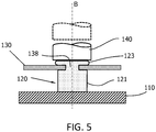
- FIG 5 illustrates this method according to the prior art of fixing a rigid plate 130 on a wall 110 with the aid of a pin 120.
- figure 5 is a sectional view of such a plate 130 fixed on the pin 120 at the end of this method according to the prior art.
- rigid plate is meant a plate which does not substantially deform during the process of crushing the pin 120, that is to say not visibly to the naked eye.
- the pin 120 extends in a longitudinal direction B.
- the distal portion 123 of the pin 120 is inserted into a hole 138 of the plate 130 so that the distal portion 123 has passed through the hole 138 and protrudes from the hole 138.
- proximal 121 of the pin is thus between the plate 130 and the wall 110.
- the proximal portion 121 can not pass through the hole 138 because its cross section is greater than the section of the hole 138.
- the plate 130 is thus maintained at the interface between the proximal portion 121 and the distal portion 123 of the peg.
- the heated face of a rivet 140 is pressed against the distal portion 123 by moving this rivet 140 along the longitudinal axis B towards the wall 110. Under the effect of pressure and heat, the distal portion 123 deforms while being sandwiched and crushed between the plate 130 and the rivet 140, and spreads on the plate 130 around the hole 138. The distal portion 123 is thus taken as an anvil between the plate 130 and the rivet 140.
- the proximal portion 121 having been slightly heated compared to the distal portion 123 and having been partially protected from the action of the rivet 140 by the plate 130, the proximal portion 121 is substantially not deformed. Then push aside the rivet 140 so as to limit the spreading of the distal portion 123 and to let this distal portion 123 to cool.
- the dashed lines represent the rivet 140 in this remote position.
- the pin 120 After cooling, the pin 120 has the shape of a mushroom whose head is the distal distal portion 123 and the foot is the proximal portion 121.
- the wall 130 is then maintained at the interface of the proximal portion 121 and the In fact, since the distal portion 123 extends laterally beyond the hole 138 of the plate 130, this distal portion can no longer slide out of the hole 138.
- the above method is repeated for each of the pins on which the plate is mounted. In this case, the pieces are successively crushed. Alternatively all the pins are simultaneously deformed and crushed by heating pins against the plate.
- the element that one wishes to fix on the pins is not a rigid plate but a more flexible element.
- this element is a membrane, for example a fabric with fibers.
- the flexibility of the element prohibits the distal portion is flattened by being crushed between this element and the rivet.
- the distal portion, and also the proximal portion deform undesirably.
- the proximal portion is crushed and shortened, or the proximal portion is bent laterally.
- such an element can not be properly maintained on a pin at a predetermined distance from the wall which is the height of the proximal portion.
- the pin and / or the element is shaped so that during the movement of the rivet, the distal portion is not crushed between this element and the rivet, even if the element is a rigid plate. This would be the case, for example, if the height-to-diameter ratio of the pin is high enough to produce a buckling of the proximal portion, or if the pin is not aligned with the direction of the compressive force applied by the riveting. In this case the pawn would be damaged and the element could not be held correctly on the pawn.
- the present invention aims to remedy these disadvantages.
- the aim of the invention is to propose a method that makes it possible to stably fix an element on a pin, and by extension on a plurality of pins.
- the combination of heating a portion of the distal portion and the pressure on this molten portion allows to deform this portion by free winding into a head, without constraint by the element.
- An undesirable deformation of the pion makes it unfit to fix the element stably.
- the element is fixed stably on the pin.
- the wall has a plurality of pions, and immediately after step (a1), a surface equalization step (b1) is carried out on a first group of pions and then in a step ( b2) step (a2) is carried out on each of the pions of the first group, this surface equalization step consisting in applying a determined pressure to compensate for the fact that all the ends of the traversing portions of the pions of the first group are not coplanar.
- a surface equalization step (b3) is carried out on a second group of pions distinct from the first group, then in a step (b4) the step (a2) on each of the pions of the second group, this surface equalization step of applying a determined pressure to compensate for the fact that all the ends of the through portions of the pions of the second group are not coplanar.
- step (b5) is carried out in which the steps (b3) and (b4) are iterated with another group of the pions.
- step (b6) is carried out in which step (b5) is iterated until the element is fixed on all the pins.
- Damage is understood to mean a deformation of the pin that renders it unsuitable to fix the element stably on this pin (for example because the proximal portion of the pin (defined above) becomes twisted, inclined, or deformed by another undesirable way.
- the element is thus fixed in a stable manner on each of the pieces.
- the invention also relates to a tank with a wall having at least one plastic pin, a through portion passing through an element.
- a portion of this through portion is deformed by free winding around the pin to form a pin head configured to hold the member on the pin.
- a wall 10 of a tank is considered.
- One or more plastic pins 20 extend along a longitudinal axis A which is substantially perpendicular to the surface of the wall 10 at the interface of the pin 20 with the wall 10.
- Figure 1A is a longitudinal sectional view of such a pin 20.
- this or these pins 20 are located on an inner wall of the tank.
- An element 30 is mounted on the pin 20 by threading the pin 20 through a pre-existing orifice on the element 30 and which passes through the element 30. If the element 30 is a woven piece, for example a fiber fabric, this orifice is one of the stitches of this element. If the element 30 is a nonwoven part, for example a sheet of plastic or metal, this orifice is a hole drilled or molded in this element 30.
- the element 30 is mounted on the pin 20 by piercing this element 30 by the pin 20.
- the pin 20 has a through portion 23 which is the portion of the pin 20 which is furthest from the wall 10 (distal portion of the pin 20), and which has passed through the member 30 during the mounting of the member 30 on the pion 20 (step (a1) of the method according to the invention).
- the proximal portion 21 of the pin 20 designates the other portion of the pin 20, which is located between the wall 10 and the element 30.
- the pin 20 is shaped so that it holds the element 30 at a fixed distance from the wall 10, namely the height (measured along the longitudinal axis A) of the proximal portion 21.
- the proximal portion 21 of the pin 20 can not pass through an orifice in the element 30 while the part distal 23 can pass through this orifice in the element 30.
- the pin flares from its distal portion 23 towards its proximal portion 21 by a conical portion located at the interface between these two parts.
- the rivet 40 has a face (contact face 43) which is intended to be heated and applied against the distal portion 23 so as to deform.
- This contact face 43 may be flat or convex.
- the element 30 is a membrane, that is to say an element of which one of the spatial dimensions (thickness) is much smaller in front of the other two, and whose compressive rigidity is much lower than the tensile rigidity .
- this element 30 is a heating membrane, and the wall 10 is part of a reservoir for containing a liquid, for example urea.
- the invention also applies to the case where the element 30 is not a membrane, for example is a rigid plate whose rigidity is at least equal to that of the pin 20.
- a portion 235 of the through portion 23 is melted and the molten portion 235 is pressed so that the fused portion 235 winds freely around the pin 20 so as to form a pion head configured to maintain the element 30 on the pin 20 (step (a2)).
- the portion 235 may represent only part or all of the through portion 23.
- melt is meant that the material of the portion 235 is heated to a heating temperature T where it has a pasty state intermediate between a solid state and a liquid state.
- this heating of the portion 235 is performed by heating the contact face 43 of the rivet 40 to the heating temperature T and placing it in contact with the end of the through portion 23. Then press the rivet 40 against the end of the through portion 23 of the pin 20 so that the contact face 43 exerts, along the longitudinal axis A, a pressure P on this through portion 23.
- This step is illustrated in FIG. Figure 1B .
- the heating temperature T is close to the melting temperature T F of the material constituting the pin 20.
- close is meant that the heating temperature T is in a range of 50 ° C around the melting temperature T F .
- the material deforms more easily and rapidly under the effect of the pressure exerted on the pin 20 by the rivet 40.
- the heating temperature T is greater than the melting temperature T F.
- the portion 235 is melted at a constant temperature T c , which is the heating temperature.
- Constant temperature means a temperature that varies little around the value T c , the temperature being in practice regulated by a control device. Thus, portion 235 is melted at a substantially constant temperature which oscillates around the average temperature T c .
- the temperature T c is of the order of 200 ° C., and the variations around this temperature are of the order of ⁇ 15 ° C.
- the portion 235 is brought rapidly to the temperature where it takes a pasty state and deforms before the remainder of the through portion 23 (located closer to the proximal portion 21) is heated.
- the deformation of the proximal portion 21 is further minimized.
- the temperature T varies during the period of contact between the pin 20 and the rivet 40.
- the temperature T increases with the duration of contact between the pin 20 and the rivet 40.
- the contact pressure P between the rivet 40 and the pin 20 varies over the period of contact between the rivet 40 and the pin 20, up to a maximum value P 0 .
- the molten portion 235 is pressed progressively, with a pressure P or a determined speed V.
- the combination of the heating temperature T of the rivet 40 and the pressure P exerted by the rivet 40 on the portion 235 leads to a deformation of the portion 235 such that the proximal portion 21 is substantially not deformed, and is essentially compressed only along the longitudinal axis A.
- the temperature T of the rivet 40 is sufficiently high (and / or the pressure P exerted by the rivet 40 or the speed of advancement V of the rivet 40 is sufficiently small) to allow time for the portion 235 to deform laterally (radially outwardly) while the proximal portion 21 does not deform undesirably.
- the pressure P exerted by the rivet 40 on the portion 235 or the forward speed V of the rivet 40 is chosen as a function of the temperature T c so that the proximal portion 21 of the stud 20 is little or not distorted.
- the proximal portion 21 does not flare up (buckling denotes, in known manner, the instability phenomenon of a structure subjected to a normal compressive force that deforms globally perpendicular to the direction of compression) or does not does not lean appreciably under the action of the snap 40.
- the membrane 30 remains positioned at a predetermined distance from the wall 10, at the interface between the through portion 23 and the proximal portion 21 of the pin 20, the membrane 30 being maintained at this distance by the through portion 23 deformed.
- the area of the maximum cross section of the through portion 23 is strictly less than the minimum cross sectional area of the proximal portion 21 of the pin 20.
- This geometry of the pin 20 contributes to keeping the membrane 30 at its initial position (before step (a2)).
- the pin 20 is cylindrical and has a shoulder at the interface between its through portion 23 and its proximal portion 21, the diameter of the cross section of the through portion 23 being smaller than the diameter of the cross section of the proximal portion. 21.
- the pin 20 is conical and flares from its through portion 23 to its proximal portion 21.
- the pin 20 has on its proximal portion 21 fins 22 which extend longitudinally from the wall and radially outwardly. These fins 22 contribute to keeping the pin 20 aligned with the longitudinal direction along the axis A. These fins are visible on some of the pins on the figure 4 .
- step (a2) the rivet 40 is moved away so that it is no longer in contact with the peg 20. This situation is illustrated in FIG. Figure 1C .
- molten portion 235 is allowed to cool and freeze more quickly in its shape taken after compression by rivet 40.
- the fused portion 235 of the pin 20 winds freely, which means that no other part than the pin 20 interferes with this winding.
- the element 30, whether flexible or rigid, does not interfere with this winding.
- the figure 2 is a longitudinal sectional view (in a plane containing the longitudinal axis A) of a pin 20 after its deformation by a rivet 40 according to the method of the invention.
- the pin 20 has a conical shape.
- the pin head formed by the deformation of the molten portion 235 has a torus shape 24 at the end of the winding process and extends radially outwardly from the remainder of the through portion (23).
- This torus 24 is centered on the longitudinal axis A and has an annular bead shape.
- the central portion of the through portion 23 is hollowed to form a depression centered on the longitudinal axis A.
- the membrane 30 is thus held on the pin 20 by the torus 24 since the torus 24 extends laterally (radially) beyond the orifice of the membrane 30 through which the through portion 23 was passed before its deformation by the method according to the invention.
- the torus 24 is attached to the circumference of the distal end of the remainder of the through portion 23 by an annular junction zone 25, visible on the figure 2 .
- the tests carried out by the inventors show that the minimum thickness E of the junction zone 25 must be greater than a threshold value Es to withstand a tearing force F A.
- the threshold thickness Es depends on the material of the pin 20. For a tearing force F A equal to 140 N and in pin 20 made of high density polyethylene (referenced HDPE CC252), the threshold thickness Es is equal to 200 ⁇ m (microns ).
- the combination of the contact pressure P exerted by the rivet 40 on the pin 20 and the heating temperature T of the rivet 40 which is such that the counter 20 is deformed by free winding into a torus centered on the longitudinal axis A may vary.
- the values of the contact pressure P and the heating temperature T can not therefore be unique and fixed for the entire range of materials capable of constituting the pion.
- the proximal portion 21 of the pin 20 is of non-zero length, as shown in the figures.
- the proximal portion 21 is of zero length.
- the membrane 30 is then fixed against the wall 10 once the fixing process according to the invention is completed.
- the invention also relates to a method for fixing an element 30 to a plurality of pins 20 extending from a wall 10.
- step (a1) described above is first carried out for each of the pins 20, so that the traversing portion 23 of each pin 20 passes through the element 30, while the proximal portion 21 of each pin 20 is located between the element 30 and the wall 10.
- a surface equalization step (b1) is performed on a first group of these pins 20.
- Step (b1) consists in applying a determined pressure on the first group only of the pins 20 to compensate for the fact that all the ends of the through portions 23 of the pions 20 of the first group are not necessarily coplanar, that is to say say are not all in the same plane. This is generally the case either because the pins 20 do not have the same height (length along the longitudinal axis A), or because the surface of the wall 10 carrying the pins 20 is not flat.
- This step avoids that under the action of the rivet 40 some pins 20 are too high pressure and are undesirably deformed.
- step (b1) several bouterolles 40, each intended to compress one of the pins 20, are approached simultaneously, that is to say the bouterolles 40 are translated together in one and the same movement along the longitudinal axis A until a first group of pins 20 comes into contact substantially simultaneously with the snap-fasteners 40.
- the contact surfaces 43 of the snaps 40 are all located in the same plane.
- the caps 40 are all mounted on the same support which is translated.
- a single bolt 40 with a large contact surface 43 capable of touching each of the pins is translated.
- the first group of pins 20 thus groups the pins 20, which, when lowering the or bouterolles 40 (or more generally a tool), the traversing portion 23 is in contact with the or bouterolles 40 without being compressed in its longitudinal direction undesirably, advantageously without being permanently compressed.
- the movement of "lowering" or the bouterolles 40 designates bringing these bouterolles 40 closer to the wall 10 carrying the pins 20.
- the rivet 40 is not necessarily heated.
- the rivet 40 is heated before step (b1) to a heating temperature, and remains heated at this heating temperature during all the steps of the method according to the invention.
- it avoids cooling and heating phases between these steps, and saves time in the treatment of pins 20.
- step (b2) the step (a2) described above is performed on each of the pawns 20 of the first group.
- the element 30 is thus fixed on all the pins 20 of the first group, these pins 20 having been deformed during the step (b2).
- the element 30 is fixed on all the pins 20 at the end of step (b2), and the process according to the invention is stopped.
- Step (b3) consists in applying a determined pressure on the second group of pins 20 to compensate for the fact that all the ends of the through portions 23 of the pins 20 of the first group are not necessarily coplanar.
- step (b4) is performed step (a2) on each of the pawns (20) of the second group.
- the element 30 is thus fixed on all the pins 20 of the second group, these pins 20 having been deformed during step (b4).
- step (b2) the tool 40 may come into contact with the second group of pegs simply because the molten portion 23 of the pegs 20 of the first group of pieces has been pressed. during step (b2).
- step (b3) is thus performed during the performance of step (b2), and step (b4) is directly carried out.
- a step (b5) is carried out in which iterates the steps (b3) and (b4) with another group of the pions (20).
- a step is carried out ( b6) in which the step (b5) is iterated until the element 30 is fixed on all the pins 20.
- the figure 4 illustrates a wall 10 which has on its inner surface several pins 20 which extend substantially along a longitudinal axis A. This figure shows the state of the pins 20 between step (b2) and step (b3).
- the membrane 30 is fixed on a first group of pins 20, and is not fixed on a second group of pins 20.
- the caps 40 are shown in dashed lines.
- the first group of pawns 20 is located on the left, the second group of pawns 20 is located on the right on the figure 4 .
- the invention also relates to a tank with a wall 10 having at least one plastic pin 20, a through portion 23 passes through a member 30, a portion 235 of this through portion 23 is deformed by free winding around the pin 20 to form a pin head configured to hold the member 30 on the pin 20.
Landscapes
- Engineering & Computer Science (AREA)
- Mechanical Engineering (AREA)
- Physics & Mathematics (AREA)
- Thermal Sciences (AREA)
- High Energy & Nuclear Physics (AREA)
- Plasma & Fusion (AREA)
- Lining Or Joining Of Plastics Or The Like (AREA)
- Casting Or Compression Moulding Of Plastics Or The Like (AREA)
- Connection Of Plates (AREA)
Description
- La présente invention concerne un procédé pour la fixation d'un élément sur une paroi d'un réservoir, cette paroi présentant au moins un pion en matière plastique.
- Un réservoir de liquide dans un véhicule comprend une paroi qui délimite un espace contenant ce liquide (par exemple il s'agit d'un réservoir destiné à contenir une solution d'urée, qui va servir à dépolluer les gaz d'échappement par réduction catalytique sélective). Dans certains cas, on cherche à fixer une plaque rigide sur une face interne de cette paroi tout en maintenant une distance prédéterminée entre cette plaque et cette face interne. Ainsi cette plaque se situe à l'intérieur du réservoir et est entièrement baignée par le liquide. Par exemple cette plaque est une plaque chauffante, qui est alors apte à chauffer le liquide.
- Pour fixer une telle plaque on utilise plusieurs pions en matière plastique qui s'étendent depuis la face interne de la paroi vers l'intérieur de la paroi, sensiblement perpendiculairement à celle-ci. La partie distale du pion désigne sa partie qui est la plus éloignée de cette face interne et qui se situe de l'autre côté de la plaque une fois cette plaque montée sur le pion (une façon de monter la plaque sur le pion est de passer la partie distale du pion par un trou de la plaque). La partie proximale du pion désigne l'autre partie du pion, qui est située entre la paroi et la plaque. Le pion est conformé de telle sorte qu'il maintient la plaque à une distance fixée de la paroi, par exemple la partie proximale du pion ne peut passer au travers du trou dans la plaque tandis que la partie distale peut passer au travers de ce trou.
- Pour fixer la plaque sur le pion, et par conséquent la solidariser avec la paroi, on applique contre la partie distale du pion, avec une certaine pression, une bouterolle chauffée au-dessus de la température ambiante. Une bouterolle désigne un outil avec une face destinée à être chauffée et appliquée contre la pièce à déformer.
- La
figure 5 illustre ce procédé selon l'art antérieur de fixation d'une plaque 130 rigide sur une paroi 110 à l'aide d'un pion 120. Lafigure 5 est une vue en coupe d'une telle plaque 130 fixée sur le pion 120 à l'issue de ce procédé selon l'art antérieur. Par plaque rigide on entend une plaque qui ne se déforme sensiblement pas durant le processus d'écrasement du pion 120, c'est-à-dire pas de façon visible à l'oeil nu. - Le pion 120 s'étend selon une direction longitudinale B. La partie distale 123 du pion 120 est insérée dans un trou 138 de la plaque 130 de telle sorte que la partie distale 123 a traversé le trou 138 et dépasse du trou 138. La partie proximale 121 du pion se situe ainsi entre la plaque 130 et la paroi 110. La partie proximale 121 ne peut passer au travers du trou 138 car sa section transversale est supérieure à la section du trou 138. La plaque 130 est ainsi maintenue à l'interface entre la partie proximale 121 et la partie distale 123 du pion.
- On appuie la face chauffée d'une bouterolle 140 contre la partie distale 123 en déplaçant cette bouterolle 140 selon l'axe longitudinal B vers la paroi 110. Sous l'effet de la pression et de la chaleur la partie distale 123 se déforme en étant prise en sandwich et écrasée entre la plaque 130 et la bouterolle 140, et s'étale sur la plaque 130 autour du trou 138. La partie distale 123 est ainsi prise en enclume entre la plaque 130 et la bouterolle 140.
- La partie proximale 121 ayant été peu chauffée comparativement à la partie distale 123 et ayant été en partie protégée de l'action de la bouterolle 140 par la plaque 130, la partie proximale 121 n'est sensiblement pas déformée. Puis on écarte la bouterolle 140 de façon à limiter l'étalement de la partie distale 123 et à laisser cette partie distale 123 se refroidir. Les traits en pointillés représentent la bouterolle 140 dans cette position écartée.
- Après son refroidissement, le pion 120 présente la forme d'un champignon dont la tête est la partie distale 123 déformée et le pied est la partie proximale 121. La paroi 130 est alors maintenue à l'interface de la partie proximale 121 et de la partie distale 123. En effet, la partie distale 123 s'étalant latéralement au-delà du trou 138 de la plaque 130, cette partie distale ne peut plus coulisser hors du trou 138.
- Le cas échéant, le procédé ci-dessus est répété pour chacun des pions sur lesquels la plaque est montée. Dans ce cas, les pions sont écrasés successivement. Alternativement tous les pions sont simultanément déformés et écrasés par des bouterolles chauffantes contre la plaque.
-
US 5 308 427 A etJP S63 212533 A - on monte ledit élément sur ledit au moins un pion de telle sorte qu'une partie traversante dudit pion traverse ledit élément,
- on fond une portion de ladite partie traversante et on appuie sur ladite portion fondue de manière à former une tête de pion configurée pour maintenir ledit élément sur ledit pion.
- Dans certains cas l'élément que l'on souhaite fixer sur les pions n'est pas une plaque rigide mais un élément plus flexible. Par exemple cet élément est une membrane, par exemple un tissu avec des fibres. Lorsqu'on utilise le procédé ci-dessus pour écraser la partie distale du pion, la flexibilité de l'élément interdit que la partie distale soit aplatie en étant écrasée entre cet élément et la bouterolle. En conséquence la partie distale, et également la partie proximale, se déforment de façon indésirable. Par exemple la partie proximale est écrasée et raccourcie, ou la partie proximale est penchée latéralement. Ainsi, un tel élément ne peut être maintenu correctement sur un pion à une distance prédéterminée de la paroi qui est la hauteur de la partie proximale.
- Il est possible aussi que le pion et/ou l'élément soit conformé de telle sorte que durant le déplacement de la bouterolle, la partie distale ne soit pas écrasée entre cet élément et la bouterolle, même si l'élément est une plaque rigide. Ce serait le cas par exemple si le rapport hauteur sur diamètre du pion est suffisamment élevé pour qu'il se produise un flambement de la partie proximale, ou si le pion n'est pas aligné avec la direction de la force de compression appliquée par la bouterolle. Dans ce cas le pion serait endommagé et l'élément ne pourrait être maintenu correctement sur le pion.
- La présente invention vise à remédier à ces inconvénients.
- L'invention vise à proposer un procédé qui permette de fixer de façon stable un élément sur un pion, et par extension sur une pluralité de pions.
- Ce but est atteint grâce au fait que le procédé comprend les étapes suivantes :
- (a1) On monte l'élément sur le pion de telle sorte qu'une partie traversante du pion traverse cet élément,
- (a2) On fond une portion de cette partie traversante et on appuie sur la portion fondue de telle sorte que la portion fondue s'enroule librement autour du pion de manière à former une tête de pion configurée pour maintenir l'élément sur le pion.
- Grâce à ces dispositions, la combinaison du chauffage d'une portion de la partie distale et de la pression sur cette portion fondue permet de déformer cette portion par enroulement libre en une tête, sans contrainte par l'élément. Il n'y a donc sensiblement pas de contrainte exercée sur la partie proximale du pion située entre l'élément et la paroi (partie qui n'a pas traversé l'élément), et pas de déformation indésirable du pion et en particulier de sa partie proximale. On qualifie d'indésirable une déformation du pion qui le rend impropre à fixer l'élément de façon stable. Ainsi, selon l'invention, l'élément est fixé de façon stable sur le pion.
- Par exemple, selon l'invention, la paroi présente une pluralité de pions, et immédiatement après l'étape (a1), on effectue une étape (b1) d'égalisation de surface sur un premier groupe des pions, puis dans une étape (b2) on effectue l'étape (a2) sur chacun des pions du premier groupe, cette étape d'égalisation de surface consistant à appliquer une pression déterminée pour compenser le fait que toutes les extrémités des parties traversantes des pions du premier groupe ne sont pas coplanaires.
- Par exemple, selon l'invention, après l'étape (b2), on effectue une étape (b3) d'égalisation de surface sur un deuxième groupe des pions distinct du premier groupe, puis dans une étape (b4) on effectue l'étape (a2) sur chacun des pions du deuxième groupe, cette étape d'égalisation de surface consistant à appliquer une pression déterminée pour compenser le fait que toutes les extrémités des parties traversantes des pions du deuxième groupe ne sont pas coplanaires.
- Par exemple, selon l'invention, après l'étape (b4), on effectue une étape (b5) dans laquelle on itère les étapes (b3) et (b4) avec un autre groupe des pions.
- Par exemple, selon l'invention, après l'étape (b5), on effectue une étape (b6) dans laquelle on itère l'étape (b5) jusqu'à ce que l'élément soit fixé sur tous les pions.
- Ainsi, dans le cas où toutes les extrémités des parties traversantes des pions de la paroi du réservoir ne contactent pas simultanément l'outil qui effectue l'étape d'égalisation, les pions qui contactent cet outil en premier (premier groupe) sont déformés sans être endommagés par cet outil, puis les pions restants sont déformés par groupes successifs.
- On entend par endommagement une déformation du pion qui le rend impropre à fixer l'élément de façon stable sur ce pion (par exemple parce que la partie proximale du pion (définie ci-dessus) devient tordue, inclinée, ou déformée d'une autre façon indésirable.
- A l'issue des répétitions, l'élément est donc fixé de façon stable sur chacun des pions.
- L'invention concerne également un réservoir avec une paroi présentant au moins un pion en matière plastique dont une partie traversante traverse un élément.
- Selon l'invention, une portion de cette partie traversante est déformée par enroulement libre autour du pion pour former une tête de pion configurée pour maintenir l'élément sur le pion.
- L'invention sera bien comprise et ses avantages apparaîtront mieux, à la lecture de la description détaillée qui suit, d'un mode de réalisation représenté à titre d'exemple non limitatif. La description se réfère aux dessins annexés sur lesquels :
- les
figures 1A, 1B, et 1C illustrent différentes étapes successives du procédé de fixation d'un élément sur un pion selon l'invention, - la
figure 2 est une vue en coupe longitudinale d'un pion déformé après application du procédé selon l'invention, - la
figure 3 représente les différentes étapes de la fixation d'un élément sur plusieurs pions d'une paroi selon le procédé de l'invention, - la
figure 4 est une vue en perspective d'un élément fixé sur plusieurs pions d'une paroi selon le procédé de l'invention, - la
figure 5 , déjà décrite, représente un pion déformé par un procédé selon l'art antérieur. - On considère une paroi 10 d'un réservoir. Un ou plusieurs pions 20 en matière plastique s'étendent selon un axe longitudinal A qui est sensiblement perpendiculaire à la surface de la paroi 10 au niveau de l'interface du pion 20 avec la paroi 10. La
figure 1A est une vue en coupe longitudinale d'un tel pion 20. - Par exemple, ce ou ces pions 20 sont situés sur une paroi 10 intérieure du réservoir.
- On décrit ci-dessous le procédé de fixation d'un élément 30 sur un pion 20. Ce procédé peut bien entendu être itéré à l'identique sur chacun des pions 20 de la paroi 10.
- Un élément 30 est monté sur le pion 20 en enfilant le pion 20 par un orifice préexistant sur l'élément 30 et qui traverse cet élément 30. Si l'élément 30 est une pièce tissée, par exemple un tissu de fibres, cet orifice est une des mailles de cet élément. Si l'élément 30 est une pièce non-tissée, par exemple une feuille de plastique ou de métal, cet orifice est un trou percé ou moulé dans cet élément 30.
- Alternativement, l'élément 30 est monté sur le pion 20 en perçant cet élément 30 par le pion 20.
- Le pion 20 présente une partie traversante 23 qui est la partie du pion 20 qui est la plus éloignée de la paroi 10 (partie distale du pion 20), et qui a traversé l'élément 30 durant le montage de l'élément 30 sur le pion 20 (étape (a1) du procédé selon l'invention). La partie proximale 21 du pion 20 désigne l'autre partie du pion 20, qui est située entre la paroi 10 et l'élément 30. Le pion 20 est conformé de telle sorte qu'il maintient l'élément 30 à une distance fixée de la paroi 10, à savoir la hauteur (mesurée selon l'axe longitudinal A) de la partie proximale 21. Par exemple la partie proximale 21 du pion 20 ne peut passer au travers d'un orifice dans l'élément 30 tandis que la partie distale 23 peut passer au travers de cet orifice dans l'élément 30.
- Par exemple le pion s'évase depuis sa partie distale 23 vers sa partie proximale 21 par une portion conique située à l'interface entre ces deux parties.
- La bouterolle 40 présente une face (face de contact 43) qui est destinée à être chauffée et appliquée contre la partie distale 23 de façon à la déformer.
- Cette face de contact 43 peut être plane ou convexe.
- L'invention est décrite ci-dessous dans le cas où l'élément 30 est plus flexible que le pion 20.
- Par exemple, l'élément 30 est une membrane, c'est-à-dire un élément dont une des dimensions spatiales (épaisseur) est très inférieure devant les deux autres, et dont la rigidité en compression est très inférieure à la rigidité en tension.
- Par exemple, cet élément 30 est une membrane chauffante, et la paroi 10 fait partie d'un réservoir destiné à contenir un liquide, par exemple de l'urée.
- Cependant l'invention s'applique également au cas où l'élément 30 n'est pas une membrane, par exemple est une plaque rigide dont la rigidité est au moins égale à celle du pion 20.
- Selon l'invention, on fond une portion 235 de la partie traversante 23 et on appuie sur la portion fondue 235 de telle sorte que la portion fondue 235 s'enroule librement autour du pion 20 de manière à former une tête de pion configurée pour maintenir l'élément 30 sur le pion 20 (étape (a2)).
- La portion 235 peut représenter une partie seulement, ou la totalité de la partie traversante 23.
- Par « fondre », on entend que le matériau de la portion 235 est chauffé jusqu'à une température de chauffage T où il présente un état pâteux intermédiaire entre un état solide et un état liquide.
- Avantageusement, ce chauffage de la portion 235 s'effectue en chauffant la face de contact 43 de la bouterolle 40 à la température de chauffage T et en la plaçant en contact avec l'extrémité de la partie traversante 23. Puis on appuie la bouterolle 40 contre l'extrémité de la partie traversante 23 du pion 20 de telle sorte que la face de contact 43 exerce, selon l'axe longitudinal A, une pression P sur cette partie traversante 23. Cette étape est illustrée en
Figure 1B . - La température de chauffage T est proche de la température de fusion TF du matériau constituant le pion 20. Par « proche » on signifie que la température de chauffage T se situe dans un intervalle de 50°C autour de la température de fusion TF.
- Ainsi, le matériau se déforme plus aisément et rapidement sous l'effet de la pression exercée sur le pion 20 par la bouterolle 40.
- Par exemple, la température de chauffage T est supérieure à la température de fusion TF.
- Par exemple, on fond la portion 235 à température constante Tc, qui est la température de chauffage.
- Par température constante, on entend une température qui varie peu autour de la valeur Tc, la température étant en pratique régulée par un dispositif de régulation. Ainsi, on fond la portion 235 à une température sensiblement constante qui oscille autour de la température moyenne Tc.
- Par exemple, pour du polyéthylène haute densité, la température Tc est de l'ordre de 200°C, et les variations autour de cette température sont de l'ordre de ±15°C.
- Ainsi, la portion 235 est portée rapidement à la température où elle prend un état pâteux et se déforme avant que le reste de la partie traversante 23 (située plus près de la partie proximale 21) ne soit chauffée. Ainsi la déformation de la partie proximale 21 est encore minimisée.
- Alternativement, la température T varie pendant la période de contact entre le pion 20 et la bouterolle 40.
- Par exemple la température T augmente avec la durée de contact entre le pion 20 et la bouterolle 40.
- La pression de contact P entre la bouterolle 40 et le pion 20 varie sur la période de contact entre la bouterolle 40 et le pion 20, jusqu'à une valeur maximale P0.
- Avantageusement, on appuie sur la portion fondue 235 de façon progressive, avec une pression P ou une vitesse V déterminée.
- Par exemple, la combinaison de la température de chauffage T de la bouterolle 40 et de la pression P exercée par la bouterolle 40 sur la portion 235 (ou, de façon équivalente, la combinaison de la température de chauffage T et de la vitesse d'avancement V de la bouterolle 40 selon l'axe longitudinal A contre cette portion 235) conduit à une déformation de la portion 235 telle que la partie proximale 21 n'est sensiblement pas déformée, et est essentiellement uniquement comprimée selon l'axe longitudinal A. Initialement (c'est-à-dire au premier contact de la bouterolle 40 avec la partie traversante 23), la température T de la bouterolle 40 est suffisamment élevée (et/ou la pression P exercée par la bouterolle 40 ou la vitesse d'avancement V de la bouterolle 40 est suffisamment faible) pour laisser le temps à la portion 235 de se déformer latéralement (radialement vers l'extérieur) tandis que la partie proximale 21 ne se déforme pas de façon indésirable.
- En particulier, la pression P exercée par la bouterolle 40 sur la portion 235 ou la vitesse d'avancement V de la bouterolle 40 est choisie en fonction de la température Tc de telle sorte que la partie proximale 21 du pion 20 est peu ou pas déformée.
- Ainsi, la partie proximale 21 ne flambe pas (le flambement désigne, de façon connue, le phénomène d'instabilité d'une structure soumise à un effort normal de compression qui se déforme de façon globale perpendiculairement à la direction de compression) ou ne se penche pas latéralement sensiblement sous l'action de la bouterolle 40.
- Ainsi, selon le procédé de l'invention, la membrane 30 reste positionnée à une distance prédéterminée de la paroi 10, à l'interface entre la partie traversante 23 et la partie proximale 21 du pion 20, la membrane 30 étant maintenue à cette distance par la partie traversante 23 déformée.
- Avantageusement, la superficie de la section transversale maximale de la partie traversante 23 est strictement inférieure à la superficie minimale de la section transversale de la partie proximale 21 du pion 20.
- Cette géométrie du pion 20 contribue à maintenir la membrane 30 à sa position initiale (avant l'étape (a2)).
- Par exemple, le pion 20 est cylindrique et présente un épaulement à l'interface entre sa partie traversante 23 et sa partie proximale 21, le diamètre de la section transversale de la partie traversante 23 étant inférieur au diamètre de la section transversale de la partie proximale 21.
- Par exemple, le pion 20 est conique et s'évase depuis sa partie traversante 23 vers sa partie proximale 21.
- Par exemple le pion 20 présente sur sa partie proximale 21 des ailettes 22 qui s'étendent longitudinalement depuis la paroi et radialement vers l'extérieur. Ces ailettes 22 contribuent à maintenir le pion 20 aligné avec la direction longitudinale selon l'axe A. Ces ailettes sont visibles sur certains des pions sur la
figure 4 . - Avantageusement, après l'étape (a2) on éloigne la bouterolle 40 de façon qu'elle ne soit plus en contact avec le pion 20. Cette situation est illustrée en
Figure 1C . - Ainsi, on permet à portion fondue 235 de se refroidir et de se figer plus rapidement dans sa forme prise après sa compression par la bouterolle 40.
- Les essais réalisés par les inventeurs montrent que la portion fondue 235 s'enroule librement autour du pion 20 de manière à former une tête de pion.
- Par enroulement d'une portion d'une pièce autour du reste de cette pièce, on entend une déformation progressive de cette portion pour former une spirale sur elle-même.
- Selon l'invention, la portion fondue 235 du pion 20 s'enroule librement, ce qui signifie qu'aucune autre pièce que le pion 20 n'interfère avec cet enroulement. En particulier, l'élément 30, qu'il soit flexible ou rigide, n'interfère pas avec cet enroulement.
- La
figure 2 est une vue en coupe longitudinale (dans un plan contenant l'axe longitudinal A) d'un pion 20 après sa déformation par une bouterolle 40 selon le procédé de l'invention. Dans cet exemple le pion 20 a une forme conique. - Sous l'action de la bouterolle 40 la portion fondue 235 se déforme par expansion latérale, puis enroulement progressif sur elle-même de sa circonférence latérale annulaire. Cet enroulement en spirale se produit initialement en direction de la partie proximale 21, dans le sens des flèches sur la
figure 2 . - Par exemple, la tête de pion formée par la déformation de la portion fondue 235 a une forme de tore 24 à l'issue du processus d'enroulement et s'étend radialement vers l'extérieur depuis le reste de la partie traversante (23). Ce tore 24 étant centré sur l'axe longitudinal A et a une forme de bourrelet annulaire.
- Dans certains cas, la portion centrale de la partie traversante 23 se creuse pour former une dépression centrée sur l'axe longitudinal A.
- La membrane 30 est ainsi maintenue sur le pion 20 par le tore 24 puisque ce tore 24 s'étend latéralement (radialement) au-delà de l'orifice de la membrane 30 par lequel la partie traversante 23 était passée avant sa déformation par le procédé selon l'invention.
- Le tore 24 est rattaché à la circonférence de l'extrémité distale du reste de la partie traversante 23 par une zone de jonction annulaire 25, visible sur la
figure 2 . - Les essais réalisés par les inventeurs montrent que l'épaisseur minimale E de la zone de jonction 25 doit être supérieure à une valeur seuil Es pour résister à une force d'arrachement FA. L'épaisseur seuil Es dépend du matériau du pion 20. Pour une force d'arrachement FA égale à 140 N et en pion 20 en polyéthylène haute densité (référencé HDPE CC252), l'épaisseur seuil Es est égale à 200 µm (microns).
- Compte tenu de la diversité des propriétés mécaniques des matériaux aptes à constituer le pion, la combinaison de la pression de contact P exercée par la bouterolle 40 sur le pion 20 et de la température de chauffage T de la bouterolle 40 qui soit telle que le pion 20 se déforme par enroulement libre en un tore centré sur l'axe longitudinal A peut varier. Les valeurs de la pression de contact P et de la température de chauffage T ne peuvent donc être uniques et fixées pour toute la gamme de matériaux aptes à constituer le pion.
- La partie proximale 21 du pion 20 est de longueur non-nulle, comme représenté sur les figures.
- Dans certains cas, la partie proximale 21 est de longueur nulle. La membrane 30 est alors fixée contre la paroi 10 une fois le procédé de fixation selon l'invention terminé.
- L'invention concerne également un procédé pour la fixation d'un élément 30 sur une pluralité de pions 20 s'étendant depuis une paroi 10.
- L'invention est décrite ci-dessous dans le cas où ces pions 20 s'étendent tous sensiblement selon une direction longitudinale A. L'invention s'applique également au cas où certains des pions 20 ne s'étendent pas selon une même direction longitudinale A.
- On effectue d'abord l'étape (a1) décrite ci-dessus pour chacun des pions 20, de telle sorte que la partie traversante 23 de chaque pion 20 passe au travers de l'élément 30, tandis que la partie proximale 21 de chaque pion 20 se situe entre l'élément 30 et la paroi 10.
- Immédiatement après l'étape (a1), on effectue une étape (b1) d'égalisation de surface sur un premier groupe de ces pions 20.
- L'étape (b1) consiste à appliquer une pression déterminée sur le premier groupe seulement des pions 20 pour compenser le fait que toutes les extrémités des parties traversantes 23 des pions 20 du premier groupe ne sont pas nécessairement coplanaires, c'est-à-dire ne se situent pas toutes dans un même plan. Cela est en général le cas soit parce que les pions 20 ne font pas la même hauteur (longueur selon l'axe longitudinal A), soit parce que la surface de la paroi 10 portant les pions 20 n'est pas plane.
- Cette étape permet d'éviter que sous l'action de la bouterolle 40 certains pions 20 subissent une pression trop élevée et soient déformés de façon indésirable.
- Dans cette étape (b1), on approche simultanément plusieurs bouterolles 40 destinées chacune à comprimer un des pions 20, c'est-à-dire que les bouterolles 40 sont translatées ensemble en un même mouvement selon l'axe longitudinal A jusqu'à ce qu'un premier groupe de pions 20 entre en contact sensiblement simultanément avec les bouterolles 40. Les surfaces de contact 43 des bouterolles 40 sont toutes situées dans le même plan. Avantageusement les bouterolles 40 sont toutes montées sur un même support qui est translaté. Alternativement, une bouterolle 40 unique avec une grande surface de contact 43 apte à toucher chacun des pions est translatée.
- Le premier groupe des pions 20 regroupe ainsi les pions 20 dont, lorsqu'on abaisse la ou les bouterolles 40 (ou plus généralement un outil), la partie traversante 23 est en contact avec la ou les bouterolles 40 sans être comprimée selon sa direction longitudinale de façon indésirable, avantageusement sans être comprimée de façon permanente.
- Le mouvement consistant à « abaisser » la ou les bouterolles 40 désigne le fait de rapprocher ces bouterolles 40 de la paroi 10 portant les pions 20.
- A ce stade, les pions 20 hors de ce premier groupe ne sont pas en contact avec la bouterolle 40.
- A ce stade, la bouterolle 40 n'est pas nécessairement chauffée.
- Avantageusement la bouterolle 40 est chauffée avant l'étape (b1) à une température de chauffage, et reste chauffée à cette température de chauffage pendant toutes les étapes du procédé selon l'invention. Ainsi, on évite des phases de refroidissement et de chauffage entre ces étapes, et on gagne de temps dans le traitement des pions 20.
- Puis, dans une étape (b2) on effectue l'étape (a2) décrite ci-dessus sur chacun des pions 20 du premier groupe.
- L'élément 30 est ainsi fixé sur tous les pions 20 du premier groupe, ces pions 20 ayant été déformé durant l'étape (b2).
- Si le premier groupe de pions 20 comprend tous les pions 20, l'élément 30 est fixé sur la totalité des pions 20 à l'issue de l'étape (b2), et on arrête le procédé selon l'invention.
- Si au contraire l'élément 30 n'est pas fixé sur la totalité des pions 20 à l'issue de l'étape (b2), on effectue une étape (b3) d'égalisation de surface sur un deuxième groupe des pions (20) distinct du premier groupe. L'étape (b3) consiste à appliquer une pression déterminée sur le deuxième groupe des pions 20 pour compenser le fait que toutes les extrémités des parties traversantes 23 des pions 20 du premier groupe ne sont pas nécessairement coplanaires.
- Puis dans une étape (b4) on effectue l'étape (a2) sur chacun des pions (20) du deuxième groupe.
- L'élément 30 est ainsi fixé sur tous les pions 20 du deuxième groupe, ces pions 20 ayant été déformé durant l'étape (b4).
- A l'issue de l'étape (b2), l'outil 40 peut se trouver mis au contact du deuxième groupe de pions, du seul fait que l'on a appuyé sur la portion fondue 23 des pions 20 du premier groupe de pions pendant l'étape (b2). Dans ce cas particulier, l'étape (b3) est ainsi réalisée pendant la réalisation de l'étape (b2), et on effectue directement l'étape (b4).
- Si nécessaire, c'est-à-dire s'il existe des pions 20 non-inclus dans les premier et deuxième groupe, sur lesquels l'élément 30 n'est donc pas fixé, on effectue une étape (b5) dans laquelle on itère les étapes (b3) et (b4) avec un autre groupe des pions (20).
- Si nécessaire, c'est-à-dire s'il existe des pions 20 non-inclus dans les premier et deuxième groupes et dans cet autre groupe, sur lesquels l'élément 30 n'est donc pas fixé, on effectue une étape (b6) dans laquelle on itère l'étape (b5) jusqu'à ce que l'élément 30 soit fixé sur tous les pions 20.
- Les différentes étapes du procédé sont représentées en
figure 3 . - Grâce à l'approche incrémentale selon l'invention comprenant à chaque incrément une étape d'égalisation puis une étape où l'on fond une portion 235 de la partie traversante 23 des pions 20, on évite que les pions 20 qui sont en contact en premier avec la bouterolle 40 subissent trop rapidement une pression trop élevée et qu'une portion 235 de leur partie traversante 23 n'ait pas le temps de fondre et de se déformer par enroulement libre, et par conséquent que ces pions 20 soient déformés de façon indésirable.
- La
figure 4 illustre une paroi 10 qui présente sur sa surface interne plusieurs pions 20 qui s'étendent sensiblement selon un axe longitudinal A. Cette figure représente l'état des pions 20 entre l'étape (b2) et l'étape (b3). Ainsi, la membrane 30 est fixée sur un premier groupe des pions 20, et n'est pas fixée sur un deuxième groupe des pions 20. - Pour la clarté de la figure, les bouterolles 40 sont représentées en traits pointillés. Le premier groupe des pions 20 est situé à gauche, le deuxième groupe des pions 20 est situé à droite sur la
figure 4 . - L'invention concerne également un réservoir avec une paroi 10 présentant au moins un pion 20 en matière plastique dont une partie traversante 23 traverse un élément 30, une portion 235 de cette partie traversante 23 est déformée par enroulement libre autour de ce pion 20 pour former une tête de pion configurée pour maintenir l'élément 30 sur le pion 20.
Claims (15)
- Procédé pour la fixation d'un élément (30) sur une paroi (10) d'un réservoir, ladite paroi (10) présentant au moins un pion (20) en matière plastique, ce procédé comprenant les étapes suivantes :(a1) On monte ledit élément (30) sur ledit au moins un pion (20) de telle sorte qu'une partie traversante (23) dudit pion (20) traverse ledit élément (30),(a2) On fond une portion (235) de ladite partie traversante (23) et on appuie sur ladite portion fondue (235) de telle sorte que ladite portion fondue (235) s'enroule librement autour dudit au moins un pion (20) de manière à former une tête de pion configurée pour maintenir ledit élément (30) sur ledit pion (20).
- Procédé selon la revendication 1 caractérisé en ce qu'on fond ladite portion (235) à température constante Tc.
- Procédé selon la revendication 2, caractérisé en ce qu'on appuie sur ladite portion fondue (235) de façon progressive, avec une pression P ou une vitesse V déterminée.
- Procédé selon la revendication 3, caractérisé en ce que ladite pression P ou ladite vitesse V est choisie en fonction de ladite température Tc de telle sorte que la partie proximale (21) dudit pion (20), qui est la partie dudit pion (20) qui n'a pas traversé ledit élément (20), est peu ou pas déformée.
- Procédé selon l'une quelconque des revendications précédentes, caractérisé en ce que ladite tête de pion a une forme de tore à l'issue du processus d'enroulement et s'étend radialement vers l'extérieur depuis le reste de ladite partie traversante (23) dudit pion (20).
- Procédé selon l'une quelconque des revendications précédentes caractérisé en ce que ledit au moins un pion (20) est situé sur une paroi intérieure dudit réservoir.
- Procédé selon l'une quelconque des revendications précédentes caractérisé en ce que ledit élément (30) est plus flexible que ledit au moins un pion (20).
- Procédé selon la revendication 7 caractérisé en ce que ledit élément (30) est une membrane.
- Procédé selon l'une quelconque des revendications précédentes, caractérisé en ce que ladite paroi (10) présente une pluralité desdits pions (20), et en ce que immédiatement après l'étape (a1), on effectue une étape (b1) d'égalisation de surface sur un premier groupe desdits pions (20), puis dans une étape (b2) on effectue l'étape (a2) sur chacun des pions (20) dudit premier groupe, ladite étape (b1) d'égalisation de surface consistant à appliquer une pression déterminée pour compenser le fait que toutes les extrémités desdites parties traversantes (23) desdits pions (20) dudit premier groupe ne sont pas coplanaires.
- Procédé selon la revendication précédente, caractérisé en ce que, à l'étape (b1), on abaisse un outil (40) sur ledit premier groupe desdits pions (20) de telle sorte que chacune desdites parties (23) des pions (20) dudit premier groupe soit en contact avec ledit outil (40) sans être comprimée selon sa direction longitudinale de façon indésirable.
- Procédé selon la revendication 9 ou 10 caractérisé en ce que, après l'étape (b2), on effectue une étape (b3) d'égalisation de surface sur un deuxième groupe desdits pions (20) distinct dudit premier groupe, puis dans une étape (b4) on effectue l'étape (a2) sur chacun des pions (20) dudit deuxième groupe, ladite étape (b3) d'égalisation de surface consistant à appliquer une pression déterminée pour compenser le fait que toutes les extrémités desdites parties traversantes (23) desdits pions (20) dudit deuxième groupe ne sont pas coplanaires.
- Procédé selon la revendication précédente caractérisé en ce que, à l'étape (b3), on abaisse ledit outil (40) sur ledit deuxième groupe de telle sorte que chacune desdites parties (23) des pions (20) dudit deuxième groupe soit en contact avec ledit outil (40) sans être comprimé selon sa direction longitudinale de façon indésirable.
- Procédé selon la revendication 11 ou 12 caractérisé en ce que, après l'étape (b4), on effectue une étape (b5) dans laquelle on itère les étapes (b3) et (b4) avec un autre groupe desdits pions (20).
- Procédé selon la revendication précédente caractérisé en ce que, après l'étape (b5), on effectue une étape (b6) dans laquelle on itère l'étape (b5) jusqu'à ce que ledit élément (30) soit fixé sur tous lesdits pions (20).
- Réservoir avec une paroi (10) présentant au moins un pion (20) en matière plastique dont une partie traversante (23) traverse un élément (30), ledit au moins un pion (20) étant caractérisé en ce qu'une portion (235) de ladite partie traversante (23) est déformée par enroulement libre autour dudit au moins un pion (20) pour former une tête de pion configurée pour maintenir ledit élément (30) sur ledit pion (20).
Applications Claiming Priority (2)
| Application Number | Priority Date | Filing Date | Title |
|---|---|---|---|
| FR1363748 | 2013-12-31 | ||
| PCT/FR2014/053531 WO2015101746A1 (fr) | 2013-12-31 | 2014-12-23 | Procede pour la fixation d'un element sur un pion |
Publications (3)
| Publication Number | Publication Date |
|---|---|
| EP3089859A1 EP3089859A1 (fr) | 2016-11-09 |
| EP3089859B1 true EP3089859B1 (fr) | 2019-07-31 |
| EP3089859B8 EP3089859B8 (fr) | 2019-09-18 |
Family
ID=52462336
Family Applications (1)
| Application Number | Title | Priority Date | Filing Date |
|---|---|---|---|
| EP14835484.8A Active EP3089859B8 (fr) | 2013-12-31 | 2014-12-23 | Procede pour la fixation d'un element sur un pion |
Country Status (6)
| Country | Link |
|---|---|
| US (1) | US20160318242A1 (fr) |
| EP (1) | EP3089859B8 (fr) |
| JP (1) | JP6524103B2 (fr) |
| KR (1) | KR20160104037A (fr) |
| CN (1) | CN105848858B (fr) |
| WO (1) | WO2015101746A1 (fr) |
Families Citing this family (1)
| Publication number | Priority date | Publication date | Assignee | Title |
|---|---|---|---|---|
| DE102019112174A1 (de) * | 2019-05-09 | 2020-11-12 | Paul Hettich Gmbh & Co. Kg | Verfahren zum Fixieren eines Kunststoffbauteils eines Beschlages an einem Metallteil und Beschlag für Möbel oder Haushaltsgeräte |
Family Cites Families (10)
| Publication number | Priority date | Publication date | Assignee | Title |
|---|---|---|---|---|
| JPS6062325U (ja) * | 1983-10-06 | 1985-05-01 | 山川工業株式会社 | 自動車用燃料タンク |
| JPS63212533A (ja) * | 1987-02-28 | 1988-09-05 | Showa Denko Kk | 合成樹脂製タンクの製造方法 |
| US5308427A (en) * | 1992-09-28 | 1994-05-03 | Ford Motor Company | Method for fastening plastic articles |
| US20030044553A1 (en) * | 2001-08-23 | 2003-03-06 | Ravi Ramanathan | Fuel tanks |
| JP4681257B2 (ja) * | 2004-06-03 | 2011-05-11 | 株式会社ニフコ | 保護板取付構造 |
| JP2008162125A (ja) * | 2006-12-28 | 2008-07-17 | Nidec Copal Corp | 熱カシメ連結構造及び熱カシメ連結方法 |
| JP2010208173A (ja) * | 2009-03-11 | 2010-09-24 | Toyoda Gosei Co Ltd | 熱カシメ構造体 |
| CN201573339U (zh) * | 2009-09-28 | 2010-09-08 | 上海施耐德低压终端电器有限公司 | 一种塑铆装置 |
| DE102010032279B4 (de) * | 2010-07-26 | 2012-09-06 | Kautex Textron Gmbh & Co. Kg | Verfahren zur Nietbefestigung eines Zubehörteils |
| JP5333584B2 (ja) * | 2010-12-08 | 2013-11-06 | トヨタ自動車株式会社 | 部材の接続方法 |
-
2014
- 2014-12-23 WO PCT/FR2014/053531 patent/WO2015101746A1/fr active Application Filing
- 2014-12-23 JP JP2016543658A patent/JP6524103B2/ja not_active Expired - Fee Related
- 2014-12-23 KR KR1020167020668A patent/KR20160104037A/ko not_active Application Discontinuation
- 2014-12-23 US US15/109,016 patent/US20160318242A1/en not_active Abandoned
- 2014-12-23 CN CN201480071179.8A patent/CN105848858B/zh active Active
- 2014-12-23 EP EP14835484.8A patent/EP3089859B8/fr active Active
Non-Patent Citations (1)
| Title |
|---|
| None * |
Also Published As
| Publication number | Publication date |
|---|---|
| KR20160104037A (ko) | 2016-09-02 |
| US20160318242A1 (en) | 2016-11-03 |
| EP3089859B8 (fr) | 2019-09-18 |
| CN105848858B (zh) | 2018-02-23 |
| WO2015101746A1 (fr) | 2015-07-09 |
| EP3089859A1 (fr) | 2016-11-09 |
| CN105848858A (zh) | 2016-08-10 |
| JP6524103B2 (ja) | 2019-06-05 |
| JP2017508923A (ja) | 2017-03-30 |
Similar Documents
| Publication | Publication Date | Title |
|---|---|---|
| EP2002164B1 (fr) | Accessoire sertissable de raccordement pour canalisations | |
| WO2008102094A2 (fr) | Rivet aveugle hautes performances notamment pour fixation de structure | |
| EP1892120B1 (fr) | Rayon pour une roue à rayons, son procédé de fabrication et roue comprenant au moins un tel rayon | |
| EP2552622B1 (fr) | Organe de rivetage et outil de pose adapté | |
| EP2188110B1 (fr) | Procédé de fabrication de tubes par soudage | |
| FR2972238A1 (fr) | Procede de pose d'un rivet a ame creuse, rivet et outil de pose adaptes | |
| WO2007023236A1 (fr) | Rivet aveugle et son procede d'enlevement | |
| EP3089859B1 (fr) | Procede pour la fixation d'un element sur un pion | |
| WO2009125330A2 (fr) | Procédé de fabrication de tubes par soudage | |
| CA2987540A1 (fr) | Profile creux tel qu'un tube realise en materiaux composite thermodurcissable et son procede | |
| WO2010061094A1 (fr) | Dispositif de soudage a double épaulement | |
| WO2015158983A1 (fr) | Assemblage riveté et procédé de fabrication associé | |
| EP1958715B1 (fr) | Procédé d'assemblage d'au moins deux éléments par l'intermédiaire d'un rivet à sertir | |
| EP2265445B1 (fr) | Rayon pour une roue a rayons, roue et procede correspondants | |
| EP2657542B1 (fr) | Procédé de fixation d'un écrou à sertir sans tête sur un panneau sandwich | |
| EP2886883B1 (fr) | Composant de fixation et d'assemblage auto-perceur | |
| FR2496831A1 (fr) | Collier de serrage de tuyau en caoutchouc ou analogue, notamment pour vehicule automobile | |
| EP3061595B1 (fr) | Procédé de fabrication de profilé creux en matériaux composites | |
| FR2732417A1 (fr) | Piece d'insertion metallique pour thermoplastique, a tenue mecanique renforcee | |
| FR3076326A1 (fr) | Dispositif de fixation, ensemble de fixation comprenant un tel dispositif et procede de fabrication d’un tel ensemble | |
| FR3103769A1 (fr) | Bras d'essuie-glace | |
| FR2959431A1 (fr) | Dispositif d'assemblage a sertir | |
| FR2904253A1 (fr) | Element d'habillage, notamment pour interieur d'automobile, et son procede de fabrication | |
| EP3801970A1 (fr) | Procédé d'assemblage d'une première pièce et d'une deuxième pièce par l'intermédiaire d'un insert | |
| EP3310546A1 (fr) | Element de fixation, ensemble comprenant ledit element de fixation, module de face avant comprenant ledit element de fixation et procede pour fixer ledit element de fixation |
Legal Events
| Date | Code | Title | Description |
|---|---|---|---|
| PUAI | Public reference made under article 153(3) epc to a published international application that has entered the european phase |
Free format text: ORIGINAL CODE: 0009012 |
|
| 17P | Request for examination filed |
Effective date: 20160708 |
|
| AK | Designated contracting states |
Kind code of ref document: A1 Designated state(s): AL AT BE BG CH CY CZ DE DK EE ES FI FR GB GR HR HU IE IS IT LI LT LU LV MC MK MT NL NO PL PT RO RS SE SI SK SM TR |
|
| AX | Request for extension of the european patent |
Extension state: BA ME |
|
| DAX | Request for extension of the european patent (deleted) | ||
| GRAP | Despatch of communication of intention to grant a patent |
Free format text: ORIGINAL CODE: EPIDOSNIGR1 |
|
| STAA | Information on the status of an ep patent application or granted ep patent |
Free format text: STATUS: GRANT OF PATENT IS INTENDED |
|
| INTG | Intention to grant announced |
Effective date: 20180312 |
|
| GRAJ | Information related to disapproval of communication of intention to grant by the applicant or resumption of examination proceedings by the epo deleted |
Free format text: ORIGINAL CODE: EPIDOSDIGR1 |
|
| STAA | Information on the status of an ep patent application or granted ep patent |
Free format text: STATUS: REQUEST FOR EXAMINATION WAS MADE |
|
| INTC | Intention to grant announced (deleted) | ||
| GRAP | Despatch of communication of intention to grant a patent |
Free format text: ORIGINAL CODE: EPIDOSNIGR1 |
|
| STAA | Information on the status of an ep patent application or granted ep patent |
Free format text: STATUS: GRANT OF PATENT IS INTENDED |
|
| INTG | Intention to grant announced |
Effective date: 20180927 |
|
| GRAJ | Information related to disapproval of communication of intention to grant by the applicant or resumption of examination proceedings by the epo deleted |
Free format text: ORIGINAL CODE: EPIDOSDIGR1 |
|
| STAA | Information on the status of an ep patent application or granted ep patent |
Free format text: STATUS: REQUEST FOR EXAMINATION WAS MADE |
|
| GRAP | Despatch of communication of intention to grant a patent |
Free format text: ORIGINAL CODE: EPIDOSNIGR1 |
|
| STAA | Information on the status of an ep patent application or granted ep patent |
Free format text: STATUS: GRANT OF PATENT IS INTENDED |
|
| INTC | Intention to grant announced (deleted) | ||
| INTG | Intention to grant announced |
Effective date: 20190225 |
|
| GRAS | Grant fee paid |
Free format text: ORIGINAL CODE: EPIDOSNIGR3 |
|
| GRAA | (expected) grant |
Free format text: ORIGINAL CODE: 0009210 |
|
| STAA | Information on the status of an ep patent application or granted ep patent |
Free format text: STATUS: THE PATENT HAS BEEN GRANTED |
|
| AK | Designated contracting states |
Kind code of ref document: B1 Designated state(s): AL AT BE BG CH CY CZ DE DK EE ES FI FR GB GR HR HU IE IS IT LI LT LU LV MC MK MT NL NO PL PT RO RS SE SI SK SM TR |
|
| REG | Reference to a national code |
Ref country code: CH Ref legal event code: EP Ref country code: GB Ref legal event code: FG4D Free format text: NOT ENGLISH |
|
| REG | Reference to a national code |
Ref country code: AT Ref legal event code: REF Ref document number: 1160459 Country of ref document: AT Kind code of ref document: T Effective date: 20190815 |
|
| REG | Reference to a national code |
Ref country code: IE Ref legal event code: FG4D Free format text: LANGUAGE OF EP DOCUMENT: FRENCH |
|
| REG | Reference to a national code |
Ref country code: DE Ref legal event code: R096 Ref document number: 602014050998 Country of ref document: DE |
|
| RAP2 | Party data changed (patent owner data changed or rights of a patent transferred) |
Owner name: PLASTIC OMNIUM ADVANCED INNOVATION AND RESEARCH |
|
| REG | Reference to a national code |
Ref country code: CH Ref legal event code: PK Free format text: RECTIFICATION B8 |
|
| REG | Reference to a national code |
Ref country code: NL Ref legal event code: MP Effective date: 20190731 |
|
| REG | Reference to a national code |
Ref country code: LT Ref legal event code: MG4D |
|
| REG | Reference to a national code |
Ref country code: AT Ref legal event code: MK05 Ref document number: 1160459 Country of ref document: AT Kind code of ref document: T Effective date: 20190731 |
|
| PG25 | Lapsed in a contracting state [announced via postgrant information from national office to epo] |
Ref country code: FI Free format text: LAPSE BECAUSE OF FAILURE TO SUBMIT A TRANSLATION OF THE DESCRIPTION OR TO PAY THE FEE WITHIN THE PRESCRIBED TIME-LIMIT Effective date: 20190731 Ref country code: HR Free format text: LAPSE BECAUSE OF FAILURE TO SUBMIT A TRANSLATION OF THE DESCRIPTION OR TO PAY THE FEE WITHIN THE PRESCRIBED TIME-LIMIT Effective date: 20190731 Ref country code: SE Free format text: LAPSE BECAUSE OF FAILURE TO SUBMIT A TRANSLATION OF THE DESCRIPTION OR TO PAY THE FEE WITHIN THE PRESCRIBED TIME-LIMIT Effective date: 20190731 Ref country code: AT Free format text: LAPSE BECAUSE OF FAILURE TO SUBMIT A TRANSLATION OF THE DESCRIPTION OR TO PAY THE FEE WITHIN THE PRESCRIBED TIME-LIMIT Effective date: 20190731 Ref country code: NL Free format text: LAPSE BECAUSE OF FAILURE TO SUBMIT A TRANSLATION OF THE DESCRIPTION OR TO PAY THE FEE WITHIN THE PRESCRIBED TIME-LIMIT Effective date: 20190731 Ref country code: BG Free format text: LAPSE BECAUSE OF FAILURE TO SUBMIT A TRANSLATION OF THE DESCRIPTION OR TO PAY THE FEE WITHIN THE PRESCRIBED TIME-LIMIT Effective date: 20191031 Ref country code: NO Free format text: LAPSE BECAUSE OF FAILURE TO SUBMIT A TRANSLATION OF THE DESCRIPTION OR TO PAY THE FEE WITHIN THE PRESCRIBED TIME-LIMIT Effective date: 20191031 Ref country code: LT Free format text: LAPSE BECAUSE OF FAILURE TO SUBMIT A TRANSLATION OF THE DESCRIPTION OR TO PAY THE FEE WITHIN THE PRESCRIBED TIME-LIMIT Effective date: 20190731 Ref country code: PT Free format text: LAPSE BECAUSE OF FAILURE TO SUBMIT A TRANSLATION OF THE DESCRIPTION OR TO PAY THE FEE WITHIN THE PRESCRIBED TIME-LIMIT Effective date: 20191202 |
|
| PG25 | Lapsed in a contracting state [announced via postgrant information from national office to epo] |
Ref country code: IS Free format text: LAPSE BECAUSE OF FAILURE TO SUBMIT A TRANSLATION OF THE DESCRIPTION OR TO PAY THE FEE WITHIN THE PRESCRIBED TIME-LIMIT Effective date: 20191130 Ref country code: GR Free format text: LAPSE BECAUSE OF FAILURE TO SUBMIT A TRANSLATION OF THE DESCRIPTION OR TO PAY THE FEE WITHIN THE PRESCRIBED TIME-LIMIT Effective date: 20191101 Ref country code: ES Free format text: LAPSE BECAUSE OF FAILURE TO SUBMIT A TRANSLATION OF THE DESCRIPTION OR TO PAY THE FEE WITHIN THE PRESCRIBED TIME-LIMIT Effective date: 20190731 Ref country code: LV Free format text: LAPSE BECAUSE OF FAILURE TO SUBMIT A TRANSLATION OF THE DESCRIPTION OR TO PAY THE FEE WITHIN THE PRESCRIBED TIME-LIMIT Effective date: 20190731 Ref country code: AL Free format text: LAPSE BECAUSE OF FAILURE TO SUBMIT A TRANSLATION OF THE DESCRIPTION OR TO PAY THE FEE WITHIN THE PRESCRIBED TIME-LIMIT Effective date: 20190731 Ref country code: RS Free format text: LAPSE BECAUSE OF FAILURE TO SUBMIT A TRANSLATION OF THE DESCRIPTION OR TO PAY THE FEE WITHIN THE PRESCRIBED TIME-LIMIT Effective date: 20190731 |
|
| PG25 | Lapsed in a contracting state [announced via postgrant information from national office to epo] |
Ref country code: TR Free format text: LAPSE BECAUSE OF FAILURE TO SUBMIT A TRANSLATION OF THE DESCRIPTION OR TO PAY THE FEE WITHIN THE PRESCRIBED TIME-LIMIT Effective date: 20190731 |
|
| PG25 | Lapsed in a contracting state [announced via postgrant information from national office to epo] |
Ref country code: IT Free format text: LAPSE BECAUSE OF FAILURE TO SUBMIT A TRANSLATION OF THE DESCRIPTION OR TO PAY THE FEE WITHIN THE PRESCRIBED TIME-LIMIT Effective date: 20190731 Ref country code: EE Free format text: LAPSE BECAUSE OF FAILURE TO SUBMIT A TRANSLATION OF THE DESCRIPTION OR TO PAY THE FEE WITHIN THE PRESCRIBED TIME-LIMIT Effective date: 20190731 Ref country code: PL Free format text: LAPSE BECAUSE OF FAILURE TO SUBMIT A TRANSLATION OF THE DESCRIPTION OR TO PAY THE FEE WITHIN THE PRESCRIBED TIME-LIMIT Effective date: 20190731 Ref country code: RO Free format text: LAPSE BECAUSE OF FAILURE TO SUBMIT A TRANSLATION OF THE DESCRIPTION OR TO PAY THE FEE WITHIN THE PRESCRIBED TIME-LIMIT Effective date: 20190731 Ref country code: DK Free format text: LAPSE BECAUSE OF FAILURE TO SUBMIT A TRANSLATION OF THE DESCRIPTION OR TO PAY THE FEE WITHIN THE PRESCRIBED TIME-LIMIT Effective date: 20190731 |
|
| PG25 | Lapsed in a contracting state [announced via postgrant information from national office to epo] |
Ref country code: CZ Free format text: LAPSE BECAUSE OF FAILURE TO SUBMIT A TRANSLATION OF THE DESCRIPTION OR TO PAY THE FEE WITHIN THE PRESCRIBED TIME-LIMIT Effective date: 20190731 Ref country code: SK Free format text: LAPSE BECAUSE OF FAILURE TO SUBMIT A TRANSLATION OF THE DESCRIPTION OR TO PAY THE FEE WITHIN THE PRESCRIBED TIME-LIMIT Effective date: 20190731 Ref country code: SM Free format text: LAPSE BECAUSE OF FAILURE TO SUBMIT A TRANSLATION OF THE DESCRIPTION OR TO PAY THE FEE WITHIN THE PRESCRIBED TIME-LIMIT Effective date: 20190731 Ref country code: IS Free format text: LAPSE BECAUSE OF FAILURE TO SUBMIT A TRANSLATION OF THE DESCRIPTION OR TO PAY THE FEE WITHIN THE PRESCRIBED TIME-LIMIT Effective date: 20200224 |
|
| REG | Reference to a national code |
Ref country code: DE Ref legal event code: R097 Ref document number: 602014050998 Country of ref document: DE |
|
| PLBE | No opposition filed within time limit |
Free format text: ORIGINAL CODE: 0009261 |
|
| STAA | Information on the status of an ep patent application or granted ep patent |
Free format text: STATUS: NO OPPOSITION FILED WITHIN TIME LIMIT |
|
| PG2D | Information on lapse in contracting state deleted |
Ref country code: IS |
|
| PG25 | Lapsed in a contracting state [announced via postgrant information from national office to epo] |
Ref country code: IS Free format text: LAPSE BECAUSE OF FAILURE TO SUBMIT A TRANSLATION OF THE DESCRIPTION OR TO PAY THE FEE WITHIN THE PRESCRIBED TIME-LIMIT Effective date: 20191030 |
|
| REG | Reference to a national code |
Ref country code: CH Ref legal event code: PL |
|
| 26N | No opposition filed |
Effective date: 20200603 |
|
| REG | Reference to a national code |
Ref country code: BE Ref legal event code: MM Effective date: 20191231 |
|
| PG25 | Lapsed in a contracting state [announced via postgrant information from national office to epo] |
Ref country code: MC Free format text: LAPSE BECAUSE OF FAILURE TO SUBMIT A TRANSLATION OF THE DESCRIPTION OR TO PAY THE FEE WITHIN THE PRESCRIBED TIME-LIMIT Effective date: 20190731 Ref country code: SI Free format text: LAPSE BECAUSE OF FAILURE TO SUBMIT A TRANSLATION OF THE DESCRIPTION OR TO PAY THE FEE WITHIN THE PRESCRIBED TIME-LIMIT Effective date: 20190731 |
|
| GBPC | Gb: european patent ceased through non-payment of renewal fee |
Effective date: 20191223 |
|
| PG25 | Lapsed in a contracting state [announced via postgrant information from national office to epo] |
Ref country code: GB Free format text: LAPSE BECAUSE OF NON-PAYMENT OF DUE FEES Effective date: 20191223 Ref country code: IE Free format text: LAPSE BECAUSE OF NON-PAYMENT OF DUE FEES Effective date: 20191223 Ref country code: LU Free format text: LAPSE BECAUSE OF NON-PAYMENT OF DUE FEES Effective date: 20191223 |
|
| PG25 | Lapsed in a contracting state [announced via postgrant information from national office to epo] |
Ref country code: BE Free format text: LAPSE BECAUSE OF NON-PAYMENT OF DUE FEES Effective date: 20191231 Ref country code: CH Free format text: LAPSE BECAUSE OF NON-PAYMENT OF DUE FEES Effective date: 20191231 Ref country code: LI Free format text: LAPSE BECAUSE OF NON-PAYMENT OF DUE FEES Effective date: 20191231 |
|
| PG25 | Lapsed in a contracting state [announced via postgrant information from national office to epo] |
Ref country code: CY Free format text: LAPSE BECAUSE OF FAILURE TO SUBMIT A TRANSLATION OF THE DESCRIPTION OR TO PAY THE FEE WITHIN THE PRESCRIBED TIME-LIMIT Effective date: 20190731 |
|
| PG25 | Lapsed in a contracting state [announced via postgrant information from national office to epo] |
Ref country code: MT Free format text: LAPSE BECAUSE OF FAILURE TO SUBMIT A TRANSLATION OF THE DESCRIPTION OR TO PAY THE FEE WITHIN THE PRESCRIBED TIME-LIMIT Effective date: 20190731 Ref country code: HU Free format text: LAPSE BECAUSE OF FAILURE TO SUBMIT A TRANSLATION OF THE DESCRIPTION OR TO PAY THE FEE WITHIN THE PRESCRIBED TIME-LIMIT; INVALID AB INITIO Effective date: 20141223 |
|
| PG25 | Lapsed in a contracting state [announced via postgrant information from national office to epo] |
Ref country code: MK Free format text: LAPSE BECAUSE OF FAILURE TO SUBMIT A TRANSLATION OF THE DESCRIPTION OR TO PAY THE FEE WITHIN THE PRESCRIBED TIME-LIMIT Effective date: 20190731 |
|
| P01 | Opt-out of the competence of the unified patent court (upc) registered |
Effective date: 20230515 |
|
| PGFP | Annual fee paid to national office [announced via postgrant information from national office to epo] |
Ref country code: FR Payment date: 20231229 Year of fee payment: 10 Ref country code: DE Payment date: 20231214 Year of fee payment: 10 |