EP3089613B1 - Tragbare sicherungsvorrichtung - Google Patents
Tragbare sicherungsvorrichtung Download PDFInfo
- Publication number
- EP3089613B1 EP3089613B1 EP15733324.6A EP15733324A EP3089613B1 EP 3089613 B1 EP3089613 B1 EP 3089613B1 EP 15733324 A EP15733324 A EP 15733324A EP 3089613 B1 EP3089613 B1 EP 3089613B1
- Authority
- EP
- European Patent Office
- Prior art keywords
- mobility aid
- fastener
- attachment
- portable
- securing device
- Prior art date
- Legal status (The legal status is an assumption and is not a legal conclusion. Google has not performed a legal analysis and makes no representation as to the accuracy of the status listed.)
- Active
Links
Images


Classifications
-
- A—HUMAN NECESSITIES
- A61—MEDICAL OR VETERINARY SCIENCE; HYGIENE
- A61H—PHYSICAL THERAPY APPARATUS, e.g. DEVICES FOR LOCATING OR STIMULATING REFLEX POINTS IN THE BODY; ARTIFICIAL RESPIRATION; MASSAGE; BATHING DEVICES FOR SPECIAL THERAPEUTIC OR HYGIENIC PURPOSES OR SPECIFIC PARTS OF THE BODY
- A61H3/00—Appliances for aiding patients or disabled persons to walk about
- A61H3/02—Crutches
- A61H3/0244—Arrangements for storing or keeping upright when not in use
-
- A—HUMAN NECESSITIES
- A45—HAND OR TRAVELLING ARTICLES
- A45B—WALKING STICKS; UMBRELLAS; LADIES' OR LIKE FANS
- A45B1/00—Sticks with supporting, hanging or carrying means
- A45B1/04—Walking sticks with means for hanging-up or with locks
-
- A—HUMAN NECESSITIES
- A45—HAND OR TRAVELLING ARTICLES
- A45B—WALKING STICKS; UMBRELLAS; LADIES' OR LIKE FANS
- A45B11/00—Umbrellas characterised by their shape or attachment
-
- A—HUMAN NECESSITIES
- A45—HAND OR TRAVELLING ARTICLES
- A45B—WALKING STICKS; UMBRELLAS; LADIES' OR LIKE FANS
- A45B25/00—Details of umbrellas
-
- A—HUMAN NECESSITIES
- A45—HAND OR TRAVELLING ARTICLES
- A45B—WALKING STICKS; UMBRELLAS; LADIES' OR LIKE FANS
- A45B3/00—Sticks combined with other objects
-
- A—HUMAN NECESSITIES
- A45—HAND OR TRAVELLING ARTICLES
- A45B—WALKING STICKS; UMBRELLAS; LADIES' OR LIKE FANS
- A45B9/00—Details
-
- A—HUMAN NECESSITIES
- A45—HAND OR TRAVELLING ARTICLES
- A45F—TRAVELLING OR CAMP EQUIPMENT: SACKS OR PACKS CARRIED ON THE BODY
- A45F5/00—Holders or carriers for hand articles; Holders or carriers for use while travelling or camping
- A45F5/004—Holders or carriers for hand articles; Holders or carriers for use while travelling or camping with an automatic spring reel
-
- A—HUMAN NECESSITIES
- A61—MEDICAL OR VETERINARY SCIENCE; HYGIENE
- A61H—PHYSICAL THERAPY APPARATUS, e.g. DEVICES FOR LOCATING OR STIMULATING REFLEX POINTS IN THE BODY; ARTIFICIAL RESPIRATION; MASSAGE; BATHING DEVICES FOR SPECIAL THERAPEUTIC OR HYGIENIC PURPOSES OR SPECIFIC PARTS OF THE BODY
- A61H3/00—Appliances for aiding patients or disabled persons to walk about
- A61H3/02—Crutches
-
- F—MECHANICAL ENGINEERING; LIGHTING; HEATING; WEAPONS; BLASTING
- F16—ENGINEERING ELEMENTS AND UNITS; GENERAL MEASURES FOR PRODUCING AND MAINTAINING EFFECTIVE FUNCTIONING OF MACHINES OR INSTALLATIONS; THERMAL INSULATION IN GENERAL
- F16B—DEVICES FOR FASTENING OR SECURING CONSTRUCTIONAL ELEMENTS OR MACHINE PARTS TOGETHER, e.g. NAILS, BOLTS, CIRCLIPS, CLAMPS, CLIPS OR WEDGES; JOINTS OR JOINTING
- F16B1/00—Devices for securing together, or preventing relative movement between, constructional elements or machine parts
-
- F—MECHANICAL ENGINEERING; LIGHTING; HEATING; WEAPONS; BLASTING
- F16—ENGINEERING ELEMENTS AND UNITS; GENERAL MEASURES FOR PRODUCING AND MAINTAINING EFFECTIVE FUNCTIONING OF MACHINES OR INSTALLATIONS; THERMAL INSULATION IN GENERAL
- F16B—DEVICES FOR FASTENING OR SECURING CONSTRUCTIONAL ELEMENTS OR MACHINE PARTS TOGETHER, e.g. NAILS, BOLTS, CIRCLIPS, CLAMPS, CLIPS OR WEDGES; JOINTS OR JOINTING
- F16B2/00—Friction-grip releasable fastenings
- F16B2/005—Means to increase the friction-coefficient
-
- F—MECHANICAL ENGINEERING; LIGHTING; HEATING; WEAPONS; BLASTING
- F16—ENGINEERING ELEMENTS AND UNITS; GENERAL MEASURES FOR PRODUCING AND MAINTAINING EFFECTIVE FUNCTIONING OF MACHINES OR INSTALLATIONS; THERMAL INSULATION IN GENERAL
- F16B—DEVICES FOR FASTENING OR SECURING CONSTRUCTIONAL ELEMENTS OR MACHINE PARTS TOGETHER, e.g. NAILS, BOLTS, CIRCLIPS, CLAMPS, CLIPS OR WEDGES; JOINTS OR JOINTING
- F16B2/00—Friction-grip releasable fastenings
- F16B2/20—Clips, i.e. with gripping action effected solely by the inherent resistance to deformation of the material of the fastening
-
- F—MECHANICAL ENGINEERING; LIGHTING; HEATING; WEAPONS; BLASTING
- F16—ENGINEERING ELEMENTS AND UNITS; GENERAL MEASURES FOR PRODUCING AND MAINTAINING EFFECTIVE FUNCTIONING OF MACHINES OR INSTALLATIONS; THERMAL INSULATION IN GENERAL
- F16B—DEVICES FOR FASTENING OR SECURING CONSTRUCTIONAL ELEMENTS OR MACHINE PARTS TOGETHER, e.g. NAILS, BOLTS, CIRCLIPS, CLAMPS, CLIPS OR WEDGES; JOINTS OR JOINTING
- F16B47/00—Suction cups for attaching purposes; Equivalent means using adhesives
-
- A—HUMAN NECESSITIES
- A45—HAND OR TRAVELLING ARTICLES
- A45B—WALKING STICKS; UMBRELLAS; LADIES' OR LIKE FANS
- A45B9/00—Details
- A45B2009/002—Accessories
-
- A—HUMAN NECESSITIES
- A45—HAND OR TRAVELLING ARTICLES
- A45B—WALKING STICKS; UMBRELLAS; LADIES' OR LIKE FANS
- A45B25/00—Details of umbrellas
- A45B2025/003—Accessories not covered by groups A45B25/24 - A45B25/30
-
- A—HUMAN NECESSITIES
- A61—MEDICAL OR VETERINARY SCIENCE; HYGIENE
- A61H—PHYSICAL THERAPY APPARATUS, e.g. DEVICES FOR LOCATING OR STIMULATING REFLEX POINTS IN THE BODY; ARTIFICIAL RESPIRATION; MASSAGE; BATHING DEVICES FOR SPECIAL THERAPEUTIC OR HYGIENIC PURPOSES OR SPECIFIC PARTS OF THE BODY
- A61H3/00—Appliances for aiding patients or disabled persons to walk about
- A61H2003/002—Appliances for aiding patients or disabled persons to walk about with attached or incorporated article carrying means
-
- A—HUMAN NECESSITIES
- A61—MEDICAL OR VETERINARY SCIENCE; HYGIENE
- A61H—PHYSICAL THERAPY APPARATUS, e.g. DEVICES FOR LOCATING OR STIMULATING REFLEX POINTS IN THE BODY; ARTIFICIAL RESPIRATION; MASSAGE; BATHING DEVICES FOR SPECIAL THERAPEUTIC OR HYGIENIC PURPOSES OR SPECIFIC PARTS OF THE BODY
- A61H3/00—Appliances for aiding patients or disabled persons to walk about
- A61H3/02—Crutches
- A61H3/0244—Arrangements for storing or keeping upright when not in use
- A61H2003/0255—Arrangements for storing or keeping upright when not in use on a single crutch for being fixed on or supported by a wall, furniture or the like
-
- A—HUMAN NECESSITIES
- A61—MEDICAL OR VETERINARY SCIENCE; HYGIENE
- A61H—PHYSICAL THERAPY APPARATUS, e.g. DEVICES FOR LOCATING OR STIMULATING REFLEX POINTS IN THE BODY; ARTIFICIAL RESPIRATION; MASSAGE; BATHING DEVICES FOR SPECIAL THERAPEUTIC OR HYGIENIC PURPOSES OR SPECIFIC PARTS OF THE BODY
- A61H3/00—Appliances for aiding patients or disabled persons to walk about
- A61H3/02—Crutches
- A61H3/0244—Arrangements for storing or keeping upright when not in use
- A61H2003/0261—Arrangements for storing or keeping upright when not in use on walls or furniture for receiving single crutches
-
- A—HUMAN NECESSITIES
- A61—MEDICAL OR VETERINARY SCIENCE; HYGIENE
- A61H—PHYSICAL THERAPY APPARATUS, e.g. DEVICES FOR LOCATING OR STIMULATING REFLEX POINTS IN THE BODY; ARTIFICIAL RESPIRATION; MASSAGE; BATHING DEVICES FOR SPECIAL THERAPEUTIC OR HYGIENIC PURPOSES OR SPECIFIC PARTS OF THE BODY
- A61H2201/00—Characteristics of apparatus not provided for in the preceding codes
- A61H2201/01—Constructive details
- A61H2201/0119—Support for the device
- A61H2201/013—Suction cups
-
- A—HUMAN NECESSITIES
- A61—MEDICAL OR VETERINARY SCIENCE; HYGIENE
- A61H—PHYSICAL THERAPY APPARATUS, e.g. DEVICES FOR LOCATING OR STIMULATING REFLEX POINTS IN THE BODY; ARTIFICIAL RESPIRATION; MASSAGE; BATHING DEVICES FOR SPECIAL THERAPEUTIC OR HYGIENIC PURPOSES OR SPECIFIC PARTS OF THE BODY
- A61H2201/00—Characteristics of apparatus not provided for in the preceding codes
- A61H2201/01—Constructive details
- A61H2201/0188—Illumination related features
-
- F—MECHANICAL ENGINEERING; LIGHTING; HEATING; WEAPONS; BLASTING
- F16—ENGINEERING ELEMENTS AND UNITS; GENERAL MEASURES FOR PRODUCING AND MAINTAINING EFFECTIVE FUNCTIONING OF MACHINES OR INSTALLATIONS; THERMAL INSULATION IN GENERAL
- F16B—DEVICES FOR FASTENING OR SECURING CONSTRUCTIONAL ELEMENTS OR MACHINE PARTS TOGETHER, e.g. NAILS, BOLTS, CIRCLIPS, CLAMPS, CLIPS OR WEDGES; JOINTS OR JOINTING
- F16B2200/00—Constructional details of connections not covered for in other groups of this subclass
- F16B2200/81—Use of a material of the hooks-and-loops type
Definitions
- the present disclosure relates to a portable securing device.
- the portable securing device is suitable, but not limited for the securement of mobility aids such as a cane, a crutch, a pole, a walking stick umbrella or other walking aids in a desired position.
- Mobility aids or walking aids are mostly used to assist walking or otherwise improve the mobility of individuals, in particular individuals with mobility impairment.
- Such mobility aids include canes, crutches, poles, walking stick umbrellas or other walking aids of the like.
- Such aids although required for mobility, can become unnecessary when the user is, for example, seated or reclined.
- the aid would typically be placed against a wall or leaned against other surface(s) such as the edge of a table that is in close proximity to the user so that the user can easily reach for the aid when required.
- Mobility aids are also used by individuals with visual impairment. These mobility aids are typically in the form of a long white cane, to assist the visually impaired when walking. This cane when not held by such individuals must be stored properly as in any other walking aids as it would be very difficult and even dangerous for such individuals to retrieve or recover the cane should it slide off the surface of a wall or table and fall to the ground.
- US Patent No. 6,311,942 discloses a bedside cane holder for holding upright a walking cane at the side of a bed that has a generally planar frame to be inserted between a mattress and a box spring of a bed.
- the bedside cane holder comprises a clamp on a side of the frame that attaches to one side of the bed and is for holding a walking cane hence providing a convenient holder for a person rising from the bed.
- a holder is bulky, heavy and permanently attached to the bed. As such the holder is not easily removable and in that sense not 'portable'.
- US Publication No. 2003/0234035 discloses a walking cane holder apparatus that allows a walking cane to be removably attached to a person's clothing when in use and also prevents the cane from falling to the ground.
- a holder apparatus is for attachment to a person's clothing and is not suitable for secure attachment to other surfaces such as a wall, edge of a table, leg of a chair or any slanted surfaces.
- US Patent No. 7,422,188 discloses a walking cane clamp which provides a positive clamping means by which the walking cane is held in a secure position and a pair of clamping straps for binding around the leg of a table or chair.
- the pair of clamping straps requires a certain degree of dexterity to operate in order to ensure that the device is securely attached to the leg of a table or chair.
- Individuals who are aged and have other health problems like arthritis or weakness of the hand would find it difficult to use the pair of clamping straps to secure the device and walking cane to the leg of a table or chair.
- This device is also not suitable for secure attachment to other types of surfaces such as a wall, the edge of a table or any slanted surfaces.
- the circumference of the clamping means for receiving the walking cane is fixed meaning that the clamping means is not suitable for securely holding other walking aids which have girths that are smaller or larger than the circumference of the clamping means.
- AT10106 describes a mobile walking aid holder consisting of a glue lamp, a textile-coated rubber band and a metal ring.
- FR2916325 describes a walking assistance device comprising an integrated fastening system than can be attached to a support when the device is not in use.
- CH168901 describes a device comprising a pulling element for connecting an umbrella handle and a hat.
- DE202009017717 describes a holding device for walking aids comprising a cable or belt attachable at one end to a walking aid and connected at the other end to at least two different fastening means.
- DE202013003248 describes an anti-slip rubber sheath for a walking stick.
- the present disclosure seeks to, inter alia, provide a portable securing device for releasably securing a mobility aid such as a cane, a crutch, a pole, a walking stick umbrella or other walking aids in a desired position that overcomes, or at least alleviates, the above-mentioned problems.
- a mobility aid such as a cane, a crutch, a pole, a walking stick umbrella or other walking aids in a desired position that overcomes, or at least alleviates, the above-mentioned problems.
- a mobility aid securing device for releasably securing a mobility aid such as a cane, a crutch a pole, a walking stick umbrella or other walking aids in a desired position.
- a securing device for a mobility aid that in use could be easily attached and detached relative to a surface by a user without excessive effort. This need for easy attachment/detachment is balanced by the need for proper securement to the surface such that the secured mobility aid is able to withstand certain amount of external force from displacing the mobility aid.
- a portable securing device comprising an attachment means removably attachable to a portable object; a fastener releasably affixable to a plurality of surfaces, the fastener operable to be connected to the attachment means; wherein the fastener is movable relative to the attachment means in at least two planes.
- the distance between the fastener and attachment is adjustable.
- the fastener is operable to be connected to the attachment means via a connector having a self-retracting portion operable to reduce distance between the attachment and fastener; the length of the self-retracting portion further capable of being adjusted in any direction.
- the adjustable strap is made of a hook and loop material.
- the elastic strap is made of antibacterial silicone rubber.
- the fastener comprises a clamp to be affixed onto the plurality of surfaces and a non-slip gripping portion operable to contact the plurality of surfaces.
- the non-slip gripping portion is rubber.
- the clamp comprises a biasing means operable to be biased towards bringing at least two ends of the clamp towards each other.
- the self-retracting connector comprises a cord.
- the cord is a stainless steel chain.
- the connector comprises a reflective portion.
- the attachment and fastener are integrally moulded.
- the device further comprises a plurality of fasteners suited for affixing onto the plurality of surfaces.
- the plurality of fasteners includes clamps, clips and suction cups.
- the portable object is a mobility aid.
- the elastic strap comprises a means for holding an accessory.
- the means for holding an accessory comprises a sleeve.
- a mobility aid device having a portable means for securing to a surface, the means for securing comprising an attachment means for attachment to a portion of the mobility aid device; a fastener releasably affixable to a plurality of surfaces, the fastener operable to be connected to the attachment means; the fastener is movable relative to the attachment means in at least two planes; wherein in use the mobility aid is maintained in a desired position relative to the surface once the fastener is releasably affixed to the surface.
- the mobility aid device comprises a self-retracting connector operable to reduce distance between the attachment and fastener in operation the mobility aid device is brought as close to the surface or the edge of the surface; the length of the self-retracting portion further capable of being adjusted in any direction.
- the mobility aid device comprises a removable jacket covering an elongated portion of the mobility aid device.
- the removable jacket comprises an anti-slip sheath.
- kits for a portable securing device comprising a portable securing device defined in the previous aspect of the disclosure; and a removable jacket for covering an elongated portion of the mobility aid device.
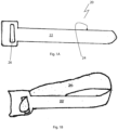
- the attachment 20 of the securing device 10 is preferably sized and shaped for removable attachment to the mobility aid.
- the fastener 30 is for releasably affixing the mobility aid to at least a surface, but preferably a plurality of surfaces at different orientation and/or planes. Examples of the plurality of surfaces include an edge of a table, table top, door handle, grab poles in buses and/or train, benches, edge of beds, table legs, safety grab poles in bathrooms, etc.
- the connector 40 connects the attachment 20 and fastener 30 and is operable to assist to keep the mobility aid in a desired position after securing onto the surface to keep it from swinging or swaying.
- the securing device 10 is operable to keep the mobility aid in a desired position that may include erect or upright position, or a substantially erect or substantially upright position, or even an inclined position. Furthermore, the device is advantageously portable, lightweight and compact.
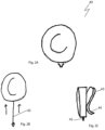
- the adjustable strap 20 is made up of two surfaces 22 and 24 and an aperture 26.
- the surfaces 22 and 24 are mutually adhesive.
- a portion of the adjustable strap 20 passes through the aperture 26 forming a loop for receiving the desired region of the mobility aid (See Figs. 8A and 8B ).
- the adjustable strap 20 and hence the device 10 is then securely attached to the mobility aid by means of the mutually adhesive surfaces 22 and 24.
- another aspect of the attachment 20 is in the form of an elastic strap 200 dimensioned to have an aperture 206 proximate one end 204 of the strap.
- the other end 208 of the elastic strap 200 preferably comprises a means for receiving an accessory 212.
- the means for receiving an accessory 212 may be in the form of a sleeve 210.
- the aperture 206 may be shaped and dimensioned to be hooked by hook 214 when attached.
- the elastic strap 200 may be wrapped around a portion/region of the mobility aid.
- the connector 40 is for connecting the fastener 30 to the attachment 20 and hence to the mobility aid.
- the self-retracting reel 400 comprises a coupling means 402 for coupling with a portion of the elastic strap 200 so as to achieve connectivity with the elastic strap 200.
- Self-retracting reel 400 may comprise a housing 404 for housing a stainless steel chain 406 biased towards being retracted into the housing.
- a free end 408 portion of the stainless steel chain extends from the self-retracting reel 400 for connectivity with the fastener 30.
- a surface 410 of the self-retracting reel 400 may be covered with reflective material 412.
- the self-retracting reel 400 preferably has a diameter of forty millimetres so that the reflective surface (covering an area) is visible at night, and the amount of stainless steel chain held within the reel 400 is of an optimal length.
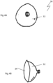
- the fastener 30 is for releasably affixing to at least one type of surface.
- the surface may be a relatively smooth non-porous surface.
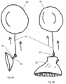
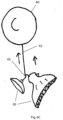
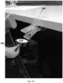
- the fastener 30 can be in a form of a suction cup.
- the suction cup has a convex surface 32 and a concave surface 34, the concave surface 34 for affixing on to a relatively smooth surface such as the surface of a wall, table, bed frame or the like and even slanted or curved surfaces.
- the suction cup is attached to the free end 45 of the self-retracting reel 40 as shown in Figs. 6A and 9A .
- the suction cup comprises an ear or protrusion for easy release of the suction cup from any surface that it has affixed to by a simple action of pulling the ear or protrusion in a direction away from the surface.
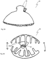
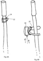
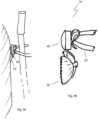
- the fastener 30 may be in the form of a clamp which can be attached to the connector 40.
- the clamp 30 is being attached to the free end of the self-retracting reel.
- the clamp comprises self-gripping jaws 38 and/or non-slip teeth that grasp onto any planar surfaces or pole or pillar-like forms so as to secure the device and hence the mobility aid to a desired position.
- the clamp comprises biasing means, such as a spring, such that the jaws 38 of the clamp are continually being urged towards each other thereby enabling the jaws to be self-gripping.
- the clamp 30 also comprises handles 36 or ears for conveniently bringing the jaws apart when a force is applied to the handles or ears 32 so that a portion of any planar surface or segment of a pole or pillar-like forms can be received between the jaws. It would be appreciated that the clamp can have any number of teeth so long as the clamp is able to grasp onto any planar surfaces or pole or pillar-like forms so as to secure the device and hence the mobility aid to a desired position.
Landscapes
- Health & Medical Sciences (AREA)
- General Engineering & Computer Science (AREA)
- Engineering & Computer Science (AREA)
- Physical Education & Sports Medicine (AREA)
- Epidemiology (AREA)
- Pain & Pain Management (AREA)
- Rehabilitation Therapy (AREA)
- Life Sciences & Earth Sciences (AREA)
- Animal Behavior & Ethology (AREA)
- General Health & Medical Sciences (AREA)
- Public Health (AREA)
- Veterinary Medicine (AREA)
- Mechanical Engineering (AREA)
- Walking Sticks, Umbrellas, And Fans (AREA)
Claims (14)
- Tragbare Sicherheitsvorrichtung (10), umfassend:ein Befestigungsmittel (20) in Form eines verstellbaren Bandes, das abnehmbar an einer Mobilitätshilfe befestigt ist, wobei das verstellbare Band ein elastisches Band ist, das ein Mittel zum Halten eines Hilfsgeräts (212) umfasst; undein Anbringungselement (30), das eine Klemme umfasst, die lösbar an einer Vielzahl von Oberflächen befestigbar ist, wobei die Klemme einen rutschfesten Gummigriffteil umfasst, der einsetzbar ist, um die Vielzahl von Oberflächen zu berühren, wobei das Anbringungselement (30) einsetzbar ist, um mit dem Befestigungsmittel (20) verbunden zu werden; wobei das Anbringungselement (30) relativ zum Befestigungsmittel (20) in zumindest zwei Ebenen bewegbar ist, wobei das Mittel zum Halten eines Hilfsgeräts (212) eine Hülse (210) mit dem Hilfsgerät umfasst, wobei das Hilfsgerät aus der aus einer batteriebetriebenen Lichtquelle, einem GPS-Ortungsgerät und einer Schallquelle bestehenden Gruppe ausgewählt ist.
- Tragbare Sicherheitsvorrichtung (10) nach Anspruch 1, wobei der Abstand zwischen dem Anbringungselement (30) und der Befestigung (20) einstellbar ist, wobei das Anbringungselement (30) gegebenenfalls einsetzbar ist, um mit dem Befestigungsmittel (20) über ein Verbindungsteil (40) mit einem selbsteinziehenden Abschnitt (400) verbunden zu werden, der einsetzbar ist, um den Abstand zwischen der Befestigung und dem Anbringungselement zu verringern; wobei die Länge des selbsteinziehenden Abschnitts (400) außerdem in jede beliebige Richtung einstellbar ist.
- Tragbare Sicherheitsvorrichtung (10) nach Anspruch 1, wobei das elastische Band aus antibakteriellem Silikonkautschuk besteht, wobei die Klemme (300) gegebenenfalls ein Vorspannmittel (304) umfasst, das einsetzbar ist, um so vorgespannt zu werden, dass es zumindest zwei Enden der Klemme zueinander bringt.
- Tragbare Sicherheitsvorrichtung (10) nach Anspruch 2, wobei der selbsteinziehende Abschnitt (400) des Verbindungsteils (40) einen Strang umfasst, wobei der Strang vorzugsweise eine Edelstahlkette ist, wobei das Verbindungsteil gegebenenfalls einen reflektierenden Abschnitt umfasst.
- Tragbare Sicherheitsvorrichtung (10) nach Anspruch 1, wobei die Vorrichtung weiters eine Vielzahl von Anbringungselementen (30) umfasst, die zum Anbringen an der Vielzahl von Oberflächen geeignet sind, und wobei die Vielzahl von Anbringungselementen (30) vorzugsweise Klemmen, Klammern und Saugkappen umfasst.
- Tragbare Sicherheitsvorrichtung (10) nach einem der vorangegangenen Ansprüche, wobei die Mobilitätshilfe einen Stock, eine Krücke, einen Stab, einen Gehstock, einen Regenschirm oder andere Gehhilfen umfasst.
- Tragbare Sicherheitsvorrichtung (10) nach Anspruch 1, wobei die zumindest zwei Ebenen eine vertikale Ebene, eine horizontale Ebene, eine Tangentialebene und eine Rotationsebene umfassen.
- Mobilitätshilfsvorrichtung mit einem tragbaren Mittel zum Befestigen an einer Oberfläche, wobei das Mittel zum Befestigen eine tragbare Sicherheitsvorrichtung nach einem der Ansprüche 1 bis 7 umfasst.
- Mobilitätshilfsvorrichtung nach Anspruch 8, die ein Verbindungsteil (40) mit einem selbsteinziehenden Abschnitt (400) umfasst, der einsetzbar ist, um den Abstand zwischen der Befestigung (20) und dem Anbringungselement (30) zu verringern, wobei die Mobilitätshilfsvorrichtung während des Einsatzes nahe zur Oberfläche oder Kante der Oberfläche gebracht wird; wobei die Länge des selbsteinziehenden Abschnitts (400) außerdem in jede beliebige Richtung einstellbar ist.
- Mobilitätshilfsvorrichtung nach Anspruch 8 oder 9, wobei die Mobilitätshilfsvorrichtung einen abnehmbaren Überzug umfasst, der einen länglichen Abschnitt der Mobilitätshilfsvorrichtung bedeckt.
- Mobilitätshilfsvorrichtung nach Anspruch 10, wobei der abnehmbare Überzug eine Antirutschummantelung umfasst.
- Kit für eine tragbare Sicherheitsvorrichtung (10), das eine Vielzahl von Befestigungsmitteln (20) und Anbringungselementen (30) nach einem der Ansprüche 1 bis 7 umfasst.
- Kit nach Anspruch 12, das weiters einen abnehmbaren Überzug zum Bedecken eines länglichen Abschnitts eines Mobilitätshilfsvorrichtung umfasst.
- Kit nach Anspruch 13, das weiters eine Mobilitätshilfsvorrichtung umfasst.
Applications Claiming Priority (3)
| Application Number | Priority Date | Filing Date | Title |
|---|---|---|---|
| SG2014000459 | 2014-01-03 | ||
| SG10201408676UA SG10201408676UA (en) | 2014-01-03 | 2014-12-24 | Portable securing device |
| PCT/SG2015/050002 WO2015102542A1 (en) | 2014-01-03 | 2015-01-02 | Portable securing device |
Publications (4)
| Publication Number | Publication Date |
|---|---|
| EP3089613A1 EP3089613A1 (de) | 2016-11-09 |
| EP3089613A4 EP3089613A4 (de) | 2017-10-11 |
| EP3089613B1 true EP3089613B1 (de) | 2023-12-13 |
| EP3089613C0 EP3089613C0 (de) | 2023-12-13 |
Family
ID=53493768
Family Applications (1)
| Application Number | Title | Priority Date | Filing Date |
|---|---|---|---|
| EP15733324.6A Active EP3089613B1 (de) | 2014-01-03 | 2015-01-02 | Tragbare sicherungsvorrichtung |
Country Status (7)
| Country | Link |
|---|---|
| US (1) | US20160317376A1 (de) |
| EP (1) | EP3089613B1 (de) |
| ES (1) | ES2970796T3 (de) |
| GB (1) | GB2535410A (de) |
| MY (1) | MY187056A (de) |
| SG (1) | SG10201408676UA (de) |
| WO (1) | WO2015102542A1 (de) |
Families Citing this family (3)
| Publication number | Priority date | Publication date | Assignee | Title |
|---|---|---|---|---|
| US11344467B2 (en) * | 2015-12-04 | 2022-05-31 | Rewalk Robotics Ltd. | Apparatus and systems for powering supports for exoskeletons |
| GB2555588B (en) * | 2016-11-01 | 2020-03-04 | Samuel Darch Ross | A walking aid retention device |
| US20220183924A1 (en) * | 2020-12-15 | 2022-06-16 | Casey Howard | Portable Massage Ball Assembly |
Family Cites Families (14)
| Publication number | Priority date | Publication date | Assignee | Title |
|---|---|---|---|---|
| AT10106B (de) | 1900-07-14 | 1902-12-10 | Julius Zobel | Hack- bezw. Ausrodemaschine. |
| CH168901A (de) | 1933-07-28 | 1934-04-30 | Benz Adolf | Vorrichtung an persönlichem Gebrauchsgegenstand. |
| US2210493A (en) * | 1939-11-20 | 1940-08-06 | Frank A Lisi | Combined walking stick and bag |
| US4027687A (en) * | 1976-08-12 | 1977-06-07 | Mcgowan Malissa A | Protective and/or decorative cover for walking aids |
| US4295483A (en) * | 1979-12-26 | 1981-10-20 | Smith Samuel W | Crutch-mounted accessory pouch |
| US4884730A (en) * | 1987-01-05 | 1989-12-05 | Carpenter Conrad L | Cane guard |
| FR2713451B1 (fr) * | 1993-12-08 | 1996-01-26 | Berthomier Jean Albert | Pince - accroche - canne. |
| JPH0937822A (ja) * | 1995-07-26 | 1997-02-10 | Sachihiro Tanaka | 杖用支持具 |
| US5964385A (en) * | 1998-03-19 | 1999-10-12 | Simon; William H. | Cane retrieval device |
| US7422188B1 (en) | 2006-09-13 | 2008-09-09 | Schlosser Harold L | Walking cane clamp |
| FR2916325B1 (fr) | 2007-05-21 | 2011-06-17 | Sitic Holding S A | Dispositif d'aide a la marche, notamment du type canne et bequille |
| AT10106U3 (de) * | 2007-09-13 | 2009-07-15 | Maria Kordik | Halterung für mobile geh-hilfen (krücke oder stock) |
| DE202009017717U1 (de) | 2009-05-26 | 2010-09-23 | Druschky, Andreas | Halteeinrichtung für Gehhilfen |
| DE202013003248U1 (de) | 2013-05-06 | 2013-07-01 | Waagen Wahner Vertriebs GmbH | Gehstockhalter; durch selbstklebende Gummiummantelung kein Umfallen eines Gehstocks, Spazierstocks, Krücken mehr |
-
2014
- 2014-12-24 SG SG10201408676UA patent/SG10201408676UA/en unknown
-
2015
- 2015-01-02 ES ES15733324T patent/ES2970796T3/es active Active
- 2015-01-02 GB GB1610588.4A patent/GB2535410A/en not_active Withdrawn
- 2015-01-02 US US15/109,449 patent/US20160317376A1/en not_active Abandoned
- 2015-01-02 WO PCT/SG2015/050002 patent/WO2015102542A1/en not_active Ceased
- 2015-01-02 MY MYPI2016702445A patent/MY187056A/en unknown
- 2015-01-02 EP EP15733324.6A patent/EP3089613B1/de active Active
Also Published As
| Publication number | Publication date |
|---|---|
| ES2970796T3 (es) | 2024-05-30 |
| US20160317376A1 (en) | 2016-11-03 |
| EP3089613A4 (de) | 2017-10-11 |
| EP3089613C0 (de) | 2023-12-13 |
| SG10201408676UA (en) | 2015-08-28 |
| WO2015102542A1 (en) | 2015-07-09 |
| GB201610588D0 (en) | 2016-08-03 |
| EP3089613A1 (de) | 2016-11-09 |
| GB2535410A (en) | 2016-08-17 |
| MY187056A (en) | 2021-08-28 |
Similar Documents
| Publication | Publication Date | Title |
|---|---|---|
| US8978677B2 (en) | Multi-functional walking aid | |
| US20150001359A1 (en) | Removable accessory clip system and flange for a removable accessory clip system | |
| US11123593B2 (en) | Exercise accessories and system | |
| US20040020524A1 (en) | Walking cane retainer | |
| EP3089613B1 (de) | Tragbare sicherungsvorrichtung | |
| US6966470B1 (en) | Carrying bag assembly | |
| US20100012804A1 (en) | Apparatus for securing a hanging objection to a fixed object | |
| US10016082B1 (en) | Garment removal apparatus and method | |
| US9307855B2 (en) | Cane clamp for walking aides | |
| US20100243689A1 (en) | Hands-free umbrella harness | |
| HK1230038B (en) | Portable securing device | |
| HK1230038A1 (en) | Portable securing device | |
| US7278668B1 (en) | Modular gripping assistive device | |
| US20090114692A1 (en) | Crutch support system | |
| US20190045959A1 (en) | Garment Removal Apparatus and Method | |
| US10058150B2 (en) | Devices, systems, and methods for combining mobility and reaching aids | |
| US9186011B2 (en) | Bra assistive device | |
| JP3179312U (ja) | 買い物袋保持用肩掛け紐 | |
| JP3165458U (ja) | 杖、ステッキ等のホルダー | |
| JP5006469B1 (ja) | 杖 | |
| JP2006081839A (ja) | 杖転倒防止具 | |
| JP5749383B1 (ja) | 固定具 | |
| KR20130079472A (ko) | 집게부가 설치된 기능성 우산 | |
| TW201036570A (en) | Hand-free umbrella supporting device | |
| US12434096B2 (en) | Device for enhancing grip strength |
Legal Events
| Date | Code | Title | Description |
|---|---|---|---|
| PUAI | Public reference made under article 153(3) epc to a published international application that has entered the european phase |
Free format text: ORIGINAL CODE: 0009012 |
|
| 17P | Request for examination filed |
Effective date: 20160725 |
|
| AK | Designated contracting states |
Kind code of ref document: A1 Designated state(s): AL AT BE BG CH CY CZ DE DK EE ES FI FR GB GR HR HU IE IS IT LI LT LU LV MC MK MT NL NO PL PT RO RS SE SI SK SM TR |
|
| AX | Request for extension of the european patent |
Extension state: BA ME |
|
| DAX | Request for extension of the european patent (deleted) | ||
| A4 | Supplementary search report drawn up and despatched |
Effective date: 20170907 |
|
| RIC1 | Information provided on ipc code assigned before grant |
Ipc: A45B 3/00 20060101ALI20170901BHEP Ipc: A45B 1/04 20060101AFI20170901BHEP Ipc: A61H 3/02 20060101ALI20170901BHEP Ipc: A45B 9/00 20060101ALI20170901BHEP |
|
| REG | Reference to a national code |
Ref country code: HK Ref legal event code: DE Ref document number: 1230038 Country of ref document: HK |
|
| STAA | Information on the status of an ep patent application or granted ep patent |
Free format text: STATUS: EXAMINATION IS IN PROGRESS |
|
| 17Q | First examination report despatched |
Effective date: 20190523 |
|
| GRAP | Despatch of communication of intention to grant a patent |
Free format text: ORIGINAL CODE: EPIDOSNIGR1 |
|
| STAA | Information on the status of an ep patent application or granted ep patent |
Free format text: STATUS: GRANT OF PATENT IS INTENDED |
|
| INTG | Intention to grant announced |
Effective date: 20230724 |
|
| GRAS | Grant fee paid |
Free format text: ORIGINAL CODE: EPIDOSNIGR3 |
|
| GRAA | (expected) grant |
Free format text: ORIGINAL CODE: 0009210 |
|
| STAA | Information on the status of an ep patent application or granted ep patent |
Free format text: STATUS: THE PATENT HAS BEEN GRANTED |
|
| AK | Designated contracting states |
Kind code of ref document: B1 Designated state(s): AL AT BE BG CH CY CZ DE DK EE ES FI FR GB GR HR HU IE IS IT LI LT LU LV MC MK MT NL NO PL PT RO RS SE SI SK SM TR |
|
| REG | Reference to a national code |
Ref country code: GB Ref legal event code: FG4D |
|
| REG | Reference to a national code |
Ref country code: CH Ref legal event code: EP |
|
| REG | Reference to a national code |
Ref country code: DE Ref legal event code: R096 Ref document number: 602015086919 Country of ref document: DE |
|
| REG | Reference to a national code |
Ref country code: IE Ref legal event code: FG4D |
|
| U01 | Request for unitary effect filed |
Effective date: 20240102 |
|
| U07 | Unitary effect registered |
Designated state(s): AT BE BG DE DK EE FI FR IT LT LU LV MT NL PT SE SI Effective date: 20240111 |
|
| U20 | Renewal fee for the european patent with unitary effect paid |
Year of fee payment: 10 Effective date: 20240129 |
|
| PG25 | Lapsed in a contracting state [announced via postgrant information from national office to epo] |
Ref country code: GR Free format text: LAPSE BECAUSE OF FAILURE TO SUBMIT A TRANSLATION OF THE DESCRIPTION OR TO PAY THE FEE WITHIN THE PRESCRIBED TIME-LIMIT Effective date: 20240314 |
|
| PG25 | Lapsed in a contracting state [announced via postgrant information from national office to epo] |
Ref country code: GR Free format text: LAPSE BECAUSE OF FAILURE TO SUBMIT A TRANSLATION OF THE DESCRIPTION OR TO PAY THE FEE WITHIN THE PRESCRIBED TIME-LIMIT Effective date: 20240314 |
|
| REG | Reference to a national code |
Ref country code: ES Ref legal event code: FG2A Ref document number: 2970796 Country of ref document: ES Kind code of ref document: T3 Effective date: 20240530 |
|
| PG25 | Lapsed in a contracting state [announced via postgrant information from national office to epo] |
Ref country code: RS Free format text: LAPSE BECAUSE OF FAILURE TO SUBMIT A TRANSLATION OF THE DESCRIPTION OR TO PAY THE FEE WITHIN THE PRESCRIBED TIME-LIMIT Effective date: 20231213 Ref country code: NO Free format text: LAPSE BECAUSE OF FAILURE TO SUBMIT A TRANSLATION OF THE DESCRIPTION OR TO PAY THE FEE WITHIN THE PRESCRIBED TIME-LIMIT Effective date: 20240313 Ref country code: HR Free format text: LAPSE BECAUSE OF FAILURE TO SUBMIT A TRANSLATION OF THE DESCRIPTION OR TO PAY THE FEE WITHIN THE PRESCRIBED TIME-LIMIT Effective date: 20231213 |
|
| PG25 | Lapsed in a contracting state [announced via postgrant information from national office to epo] |
Ref country code: IS Free format text: LAPSE BECAUSE OF FAILURE TO SUBMIT A TRANSLATION OF THE DESCRIPTION OR TO PAY THE FEE WITHIN THE PRESCRIBED TIME-LIMIT Effective date: 20240413 |
|
| PG25 | Lapsed in a contracting state [announced via postgrant information from national office to epo] |
Ref country code: CZ Free format text: LAPSE BECAUSE OF FAILURE TO SUBMIT A TRANSLATION OF THE DESCRIPTION OR TO PAY THE FEE WITHIN THE PRESCRIBED TIME-LIMIT Effective date: 20231213 |
|
| PG25 | Lapsed in a contracting state [announced via postgrant information from national office to epo] |
Ref country code: SK Free format text: LAPSE BECAUSE OF FAILURE TO SUBMIT A TRANSLATION OF THE DESCRIPTION OR TO PAY THE FEE WITHIN THE PRESCRIBED TIME-LIMIT Effective date: 20231213 |
|
| PG25 | Lapsed in a contracting state [announced via postgrant information from national office to epo] |
Ref country code: SM Free format text: LAPSE BECAUSE OF FAILURE TO SUBMIT A TRANSLATION OF THE DESCRIPTION OR TO PAY THE FEE WITHIN THE PRESCRIBED TIME-LIMIT Effective date: 20231213 Ref country code: SK Free format text: LAPSE BECAUSE OF FAILURE TO SUBMIT A TRANSLATION OF THE DESCRIPTION OR TO PAY THE FEE WITHIN THE PRESCRIBED TIME-LIMIT Effective date: 20231213 Ref country code: RO Free format text: LAPSE BECAUSE OF FAILURE TO SUBMIT A TRANSLATION OF THE DESCRIPTION OR TO PAY THE FEE WITHIN THE PRESCRIBED TIME-LIMIT Effective date: 20231213 Ref country code: IS Free format text: LAPSE BECAUSE OF FAILURE TO SUBMIT A TRANSLATION OF THE DESCRIPTION OR TO PAY THE FEE WITHIN THE PRESCRIBED TIME-LIMIT Effective date: 20240413 Ref country code: CZ Free format text: LAPSE BECAUSE OF FAILURE TO SUBMIT A TRANSLATION OF THE DESCRIPTION OR TO PAY THE FEE WITHIN THE PRESCRIBED TIME-LIMIT Effective date: 20231213 |
|
| PG25 | Lapsed in a contracting state [announced via postgrant information from national office to epo] |
Ref country code: PL Free format text: LAPSE BECAUSE OF FAILURE TO SUBMIT A TRANSLATION OF THE DESCRIPTION OR TO PAY THE FEE WITHIN THE PRESCRIBED TIME-LIMIT Effective date: 20231213 |
|
| PG25 | Lapsed in a contracting state [announced via postgrant information from national office to epo] |
Ref country code: PL Free format text: LAPSE BECAUSE OF FAILURE TO SUBMIT A TRANSLATION OF THE DESCRIPTION OR TO PAY THE FEE WITHIN THE PRESCRIBED TIME-LIMIT Effective date: 20231213 |
|
| REG | Reference to a national code |
Ref country code: DE Ref legal event code: R097 Ref document number: 602015086919 Country of ref document: DE |
|
| PG25 | Lapsed in a contracting state [announced via postgrant information from national office to epo] |
Ref country code: MC Free format text: LAPSE BECAUSE OF FAILURE TO SUBMIT A TRANSLATION OF THE DESCRIPTION OR TO PAY THE FEE WITHIN THE PRESCRIBED TIME-LIMIT Effective date: 20231213 |
|
| PLBE | No opposition filed within time limit |
Free format text: ORIGINAL CODE: 0009261 |
|
| STAA | Information on the status of an ep patent application or granted ep patent |
Free format text: STATUS: NO OPPOSITION FILED WITHIN TIME LIMIT |
|
| 26N | No opposition filed |
Effective date: 20240916 |
|
| PG25 | Lapsed in a contracting state [announced via postgrant information from national office to epo] |
Ref country code: IE Free format text: LAPSE BECAUSE OF NON-PAYMENT OF DUE FEES Effective date: 20240102 |
|
| PG25 | Lapsed in a contracting state [announced via postgrant information from national office to epo] |
Ref country code: IE Free format text: LAPSE BECAUSE OF NON-PAYMENT OF DUE FEES Effective date: 20240102 |
|
| U20 | Renewal fee for the european patent with unitary effect paid |
Year of fee payment: 11 Effective date: 20250120 |
|
| PGFP | Annual fee paid to national office [announced via postgrant information from national office to epo] |
Ref country code: CH Payment date: 20250201 Year of fee payment: 11 |
|
| PG25 | Lapsed in a contracting state [announced via postgrant information from national office to epo] |
Ref country code: CY Free format text: LAPSE BECAUSE OF FAILURE TO SUBMIT A TRANSLATION OF THE DESCRIPTION OR TO PAY THE FEE WITHIN THE PRESCRIBED TIME-LIMIT; INVALID AB INITIO Effective date: 20150102 |
|
| PG25 | Lapsed in a contracting state [announced via postgrant information from national office to epo] |
Ref country code: HU Free format text: LAPSE BECAUSE OF FAILURE TO SUBMIT A TRANSLATION OF THE DESCRIPTION OR TO PAY THE FEE WITHIN THE PRESCRIBED TIME-LIMIT; INVALID AB INITIO Effective date: 20150102 |
|
| PG25 | Lapsed in a contracting state [announced via postgrant information from national office to epo] |
Ref country code: TR Free format text: LAPSE BECAUSE OF FAILURE TO SUBMIT A TRANSLATION OF THE DESCRIPTION OR TO PAY THE FEE WITHIN THE PRESCRIBED TIME-LIMIT Effective date: 20231213 |
|
| REG | Reference to a national code |
Ref country code: CH Ref legal event code: U11 Free format text: ST27 STATUS EVENT CODE: U-0-0-U10-U11 (AS PROVIDED BY THE NATIONAL OFFICE) Effective date: 20260201 |
|
| U20 | Renewal fee for the european patent with unitary effect paid |
Year of fee payment: 12 Effective date: 20260119 |
|
| PGFP | Annual fee paid to national office [announced via postgrant information from national office to epo] |
Ref country code: GB Payment date: 20260119 Year of fee payment: 12 |
|
| PGFP | Annual fee paid to national office [announced via postgrant information from national office to epo] |
Ref country code: ES Payment date: 20260202 Year of fee payment: 12 |